Globe type control valve Basically a globe type of control valve consists of two parts as follows: • Main (globe) valve body • Diaphragm type of pneumatic actuator This two valve’s part is coupled by a special coupling when the air pressure coming into the diaphragm pneumatic actuator the rubber diaphragm inside the actuator will push or pull the main (globe) valve stem/shaft downward or upward.
Transcript
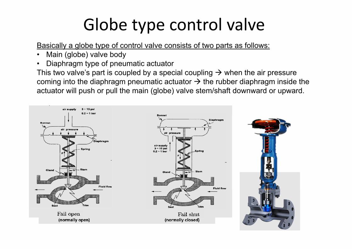
Globe type control valveBasically a globe type of control valve consists of two parts as follows:• Main (globe) valve body• Diaphragm type of pneumatic actuatorThis two valve’s part is coupled by a special coupling when the air pressure coming into the diaphragm pneumatic actuator the rubber diaphragm inside the actuator will push or pull the main (globe) valve stem/shaft downward or upward.
Globe type control valve• The main design of this control valve is globe
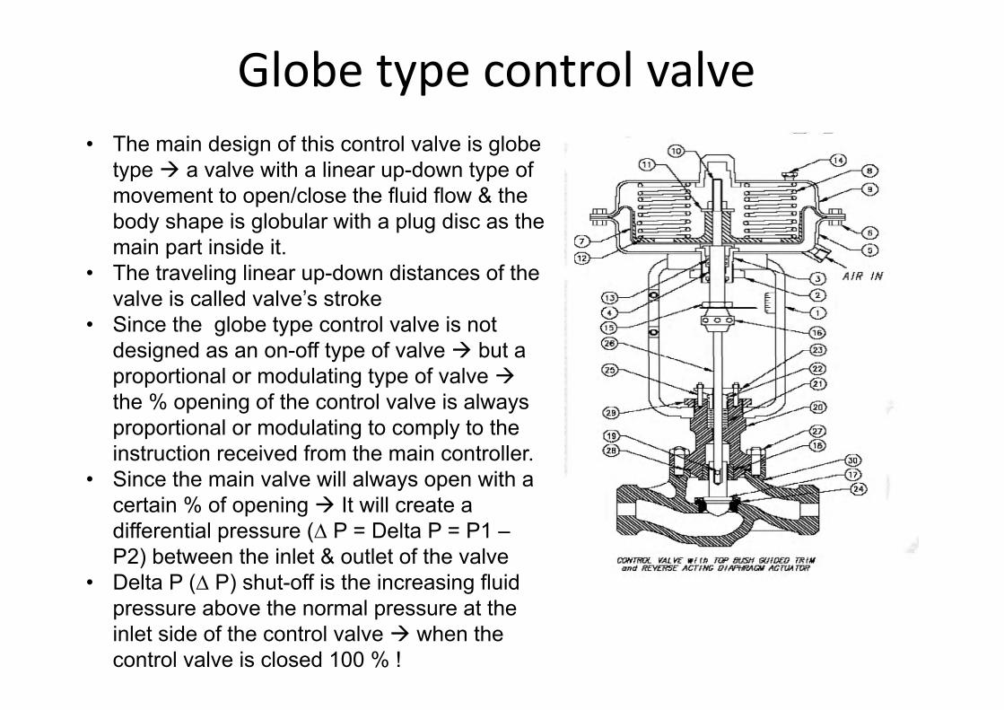
type a valve with a linear up-down type of movement to open/close the fluid flow & the body shape is globular with a plug disc as the main part inside it.
• The traveling linear up-down distances of the valve is called valve’s stroke
• Since the globe type control valve is not designed as an on-off type of valve but a proportional or modulating type of valve the % opening of the control valve is always proportional or modulating to comply to the instruction received from the main controller.
• Since the main valve will always open with a certain % of opening It will create a differential pressure (∆ P = Delta P = P1 –P2) between the inlet & outlet of the valve
• Delta P (∆ P) shut-off is the increasing fluid pressure above the normal pressure at the inlet side of the control valve when the control valve is closed 100 % !
Globe type control valve
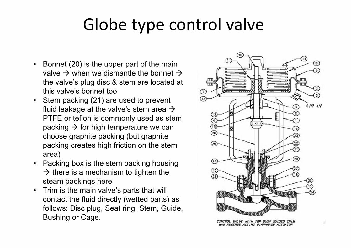
• Bonnet (20) is the upper part of the main valve when we dismantle the bonnet the valve’s plug disc & stem are located at this valve’s bonnet too
• Stem packing (21) are used to prevent fluid leakage at the valve’s stem area PTFE or teflon is commonly used as stem packing for high temperature we can choose graphite packing (but graphite packing creates high friction on the stem area)
• Packing box is the stem packing housing there is a mechanism to tighten the steam packings here
• Trim is the main valve’s parts that will contact the fluid directly (wetted parts) as follows: Disc plug, Seat ring, Stem, Guide, Bushing or Cage.
Globe type control valve
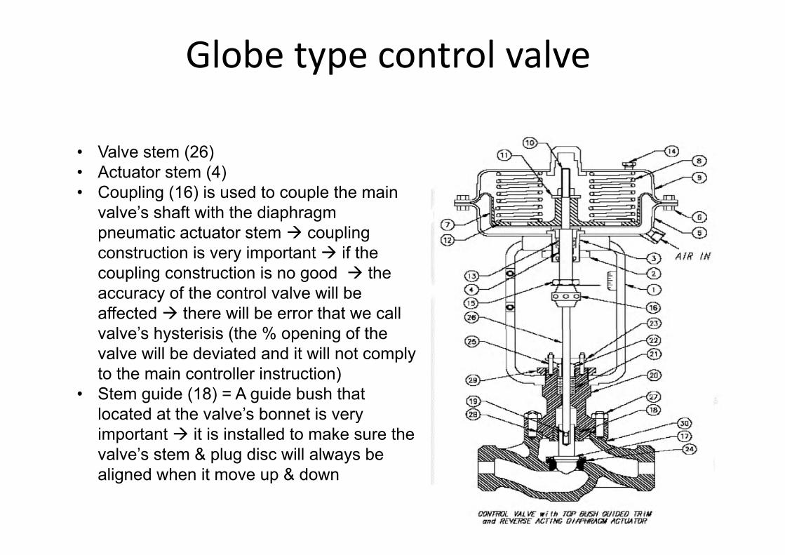
• Valve stem (26)• Actuator stem (4)• Coupling (16) is used to couple the main
valve’s shaft with the diaphragm pneumatic actuator stem coupling construction is very important if the coupling construction is no good the accuracy of the control valve will be affected there will be error that we call valve’s hysterisis (the % opening of the valve will be deviated and it will not comply to the main controller instruction)
• Stem guide (18) = A guide bush that located at the valve’s bonnet is very important it is installed to make sure the valve’s stem & plug disc will always be aligned when it move up & down
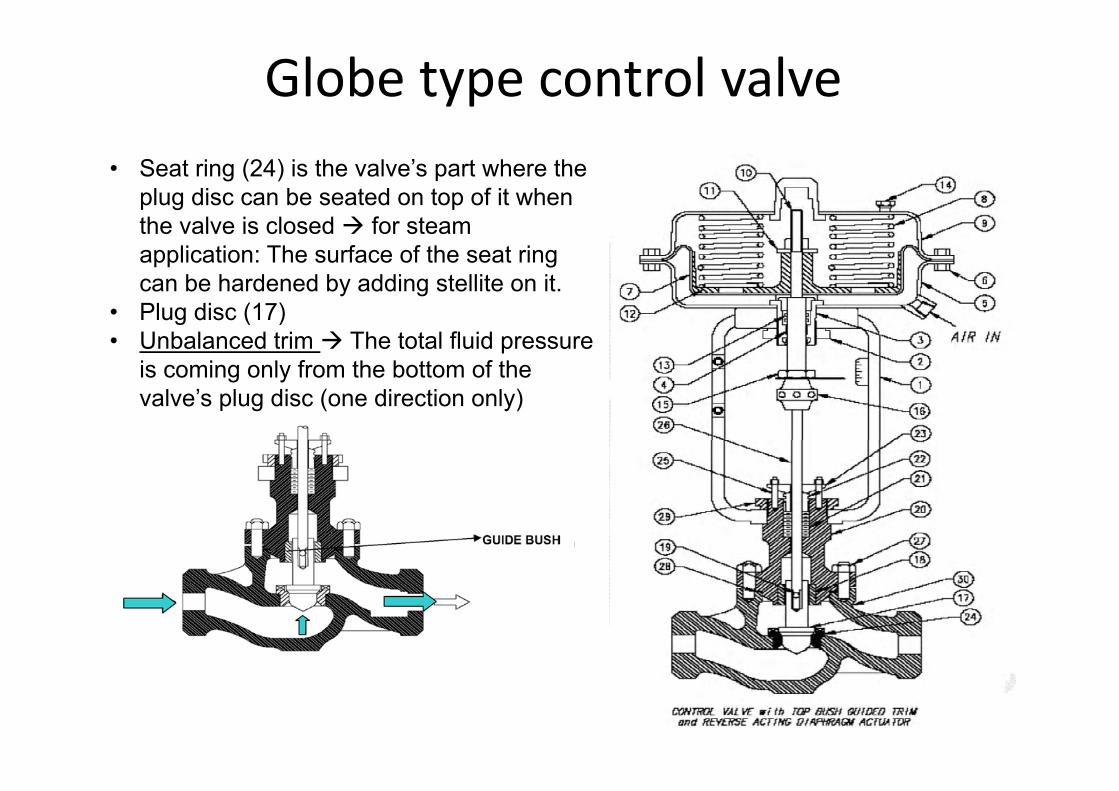
Globe type control valve• Seat ring (24) is the valve’s part where the
plug disc can be seated on top of it when the valve is closed for steam application: The surface of the seat ring can be hardened by adding stellite on it.
• Plug disc (17) • Unbalanced trim The total fluid pressure
is coming only from the bottom of the valve’s plug disc (one direction only)
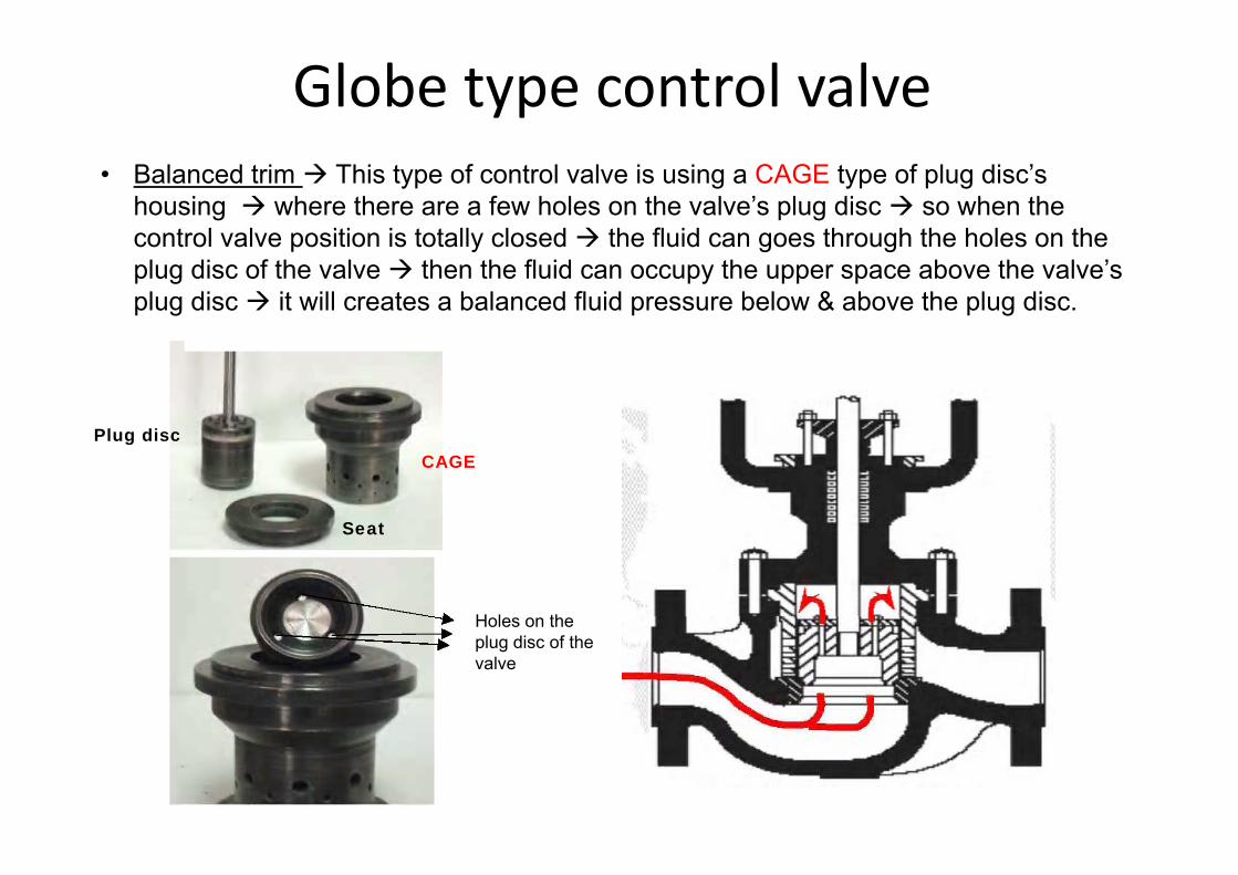
Globe type control valve• Balanced trim This type of control valve is using a CAGE type of plug disc’s
housing where there are a few holes on the valve’s plug disc so when the control valve position is totally closed the fluid can goes through the holes on the plug disc of the valve then the fluid can occupy the upper space above the valve’s plug disc it will creates a balanced fluid pressure below & above the plug disc.
Holes on the plug disc of the valve
CAGEPlug disc
Seat
Globe type control valve
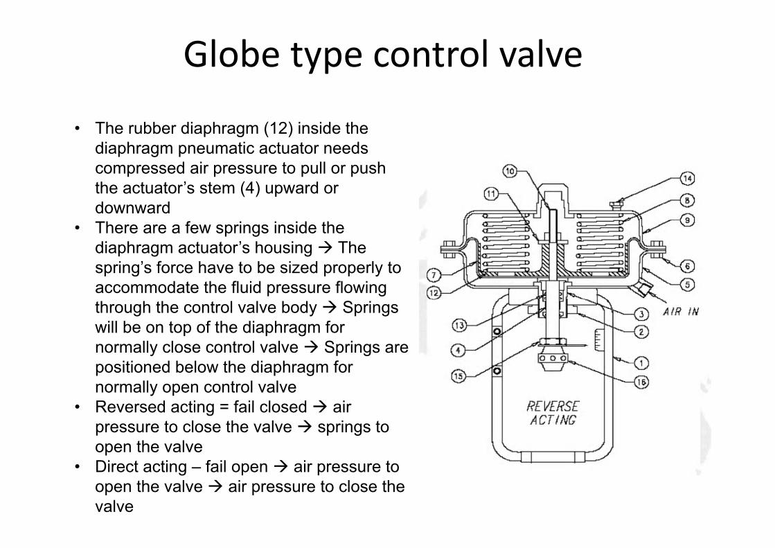
• The rubber diaphragm (12) inside the diaphragm pneumatic actuator needs compressed air pressure to pull or push the actuator’s stem (4) upward or downward
• There are a few springs inside the diaphragm actuator’s housing The spring’s force have to be sized properly to accommodate the fluid pressure flowing through the control valve body Springs will be on top of the diaphragm for normally close control valve Springs are positioned below the diaphragm for normally open control valve
• Reversed acting = fail closed air pressure to close the valve springs to open the valve
• Direct acting – fail open air pressure to open the valve air pressure to close the valve
Globe type control valve
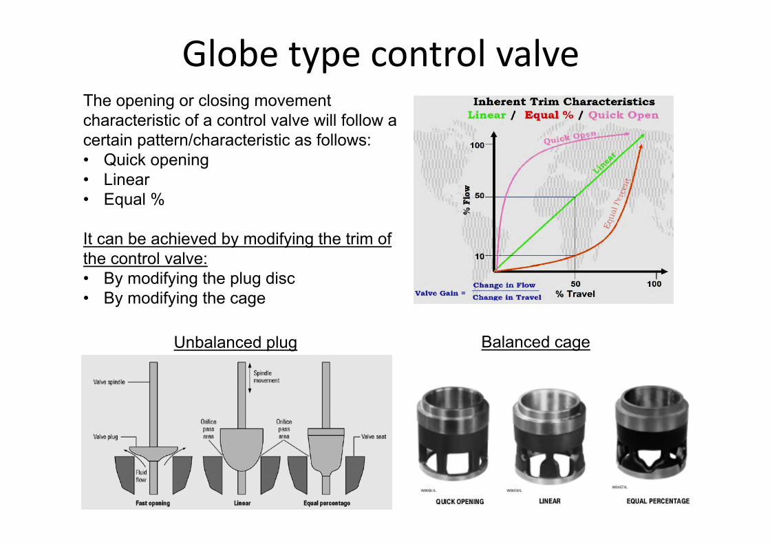
Unbalanced plug Balanced cage
The opening or closing movement characteristic of a control valve will follow a certain pattern/characteristic as follows:• Quick opening• Linear• Equal %
It can be achieved by modifying the trim of the control valve:• By modifying the plug disc • By modifying the cage
Globe type control valve
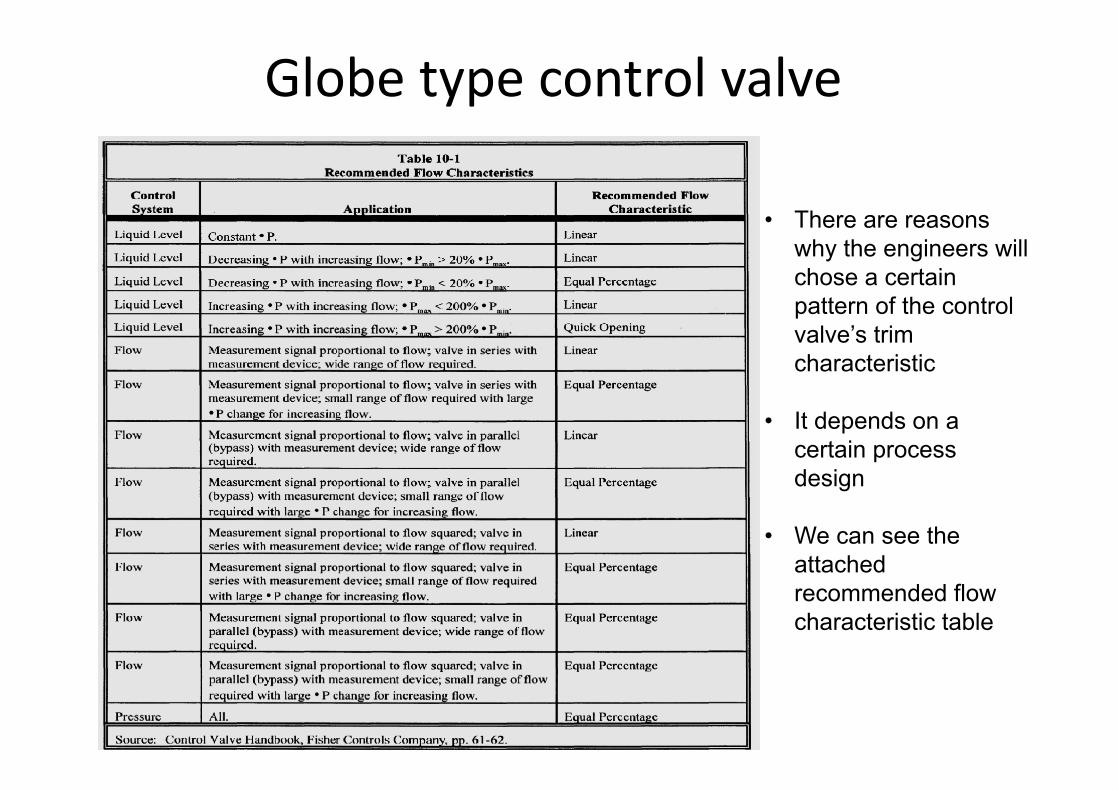
• There are reasons why the engineers will chose a certain pattern of the control valve’s trim characteristic
• It depends on a certain process design
• We can see the attached recommended flow characteristic table
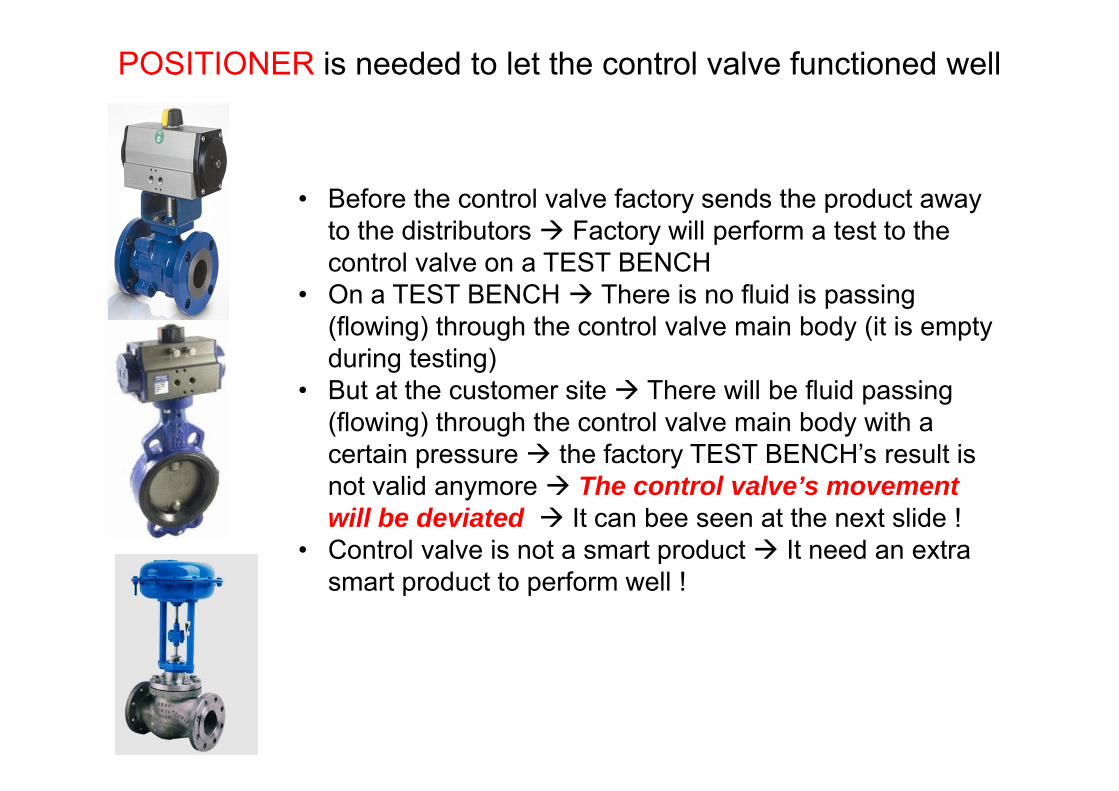
• Before the control valve factory sends the product away to the distributors Factory will perform a test to the control valve on a TEST BENCH
• On a TEST BENCH There is no fluid is passing (flowing) through the control valve main body (it is empty during testing)
• But at the customer site There will be fluid passing (flowing) through the control valve main body with a certain pressure the factory TEST BENCH’s result is not valid anymore The control valve’s movement will be deviated It can bee seen at the next slide !
• Control valve is not a smart product It need an extra smart product to perform well !
POSITIONER is needed to let the control valve functioned well
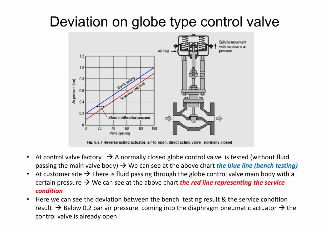
• At control valve factory A normally closed globe control valve is tested (without fluid passing the main valve body) We can see at the above chart the blue line (bench testing)
• At customer site There is fluid passing through the globe control valve main body with a certain pressure We can see at the above chart the red line representing the service condition
• Here we can see the deviation between the bench testing result & the service condition result Below 0.2 bar air pressure coming into the diaphragm pneumatic actuator the control valve is already open !
Deviation on globe type control valve
Deviation on globe type control valve
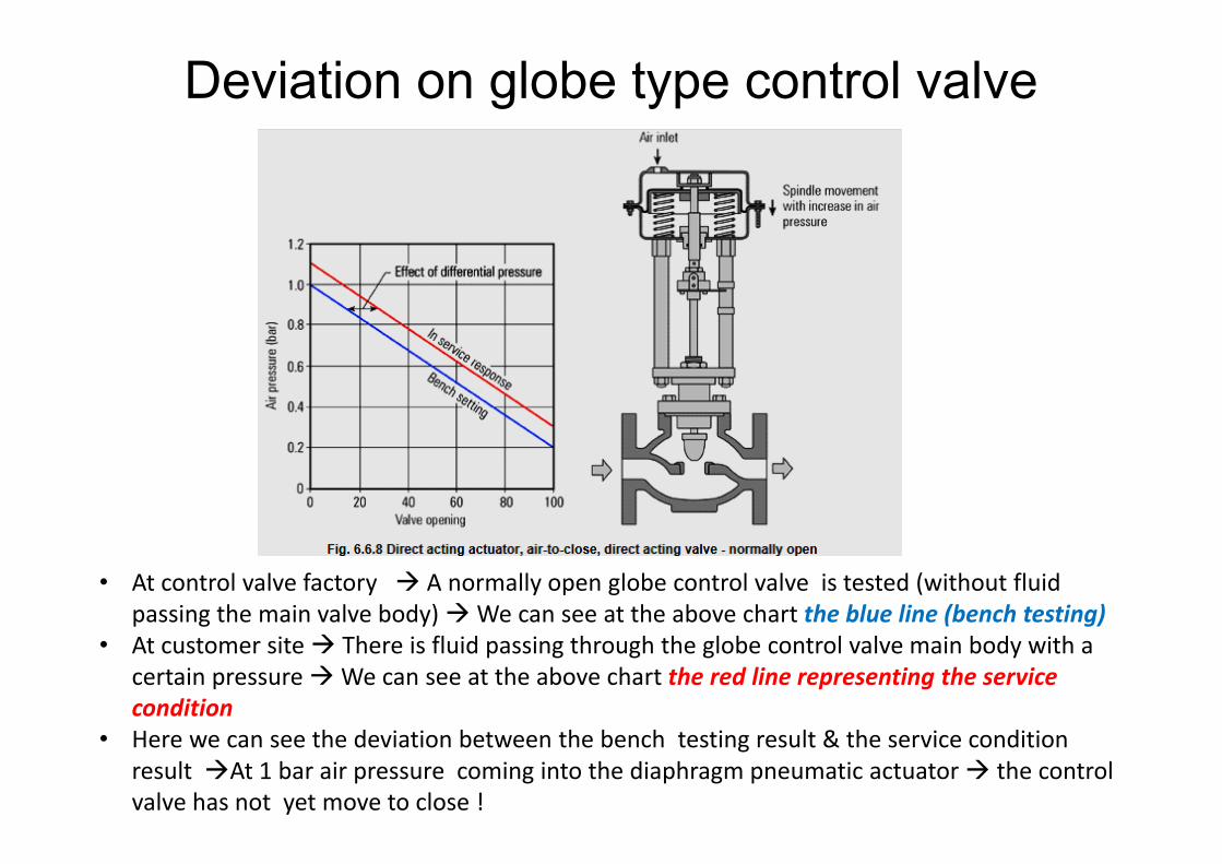
• At control valve factory A normally open globe control valve is tested (without fluid passing the main valve body) We can see at the above chart the blue line (bench testing)
• At customer site There is fluid passing through the globe control valve main body with a certain pressure We can see at the above chart the red line representing the service condition
• Here we can see the deviation between the bench testing result & the service condition result At 1 bar air pressure coming into the diaphragm pneumatic actuator the control valve has not yet move to close !
POSITIONER
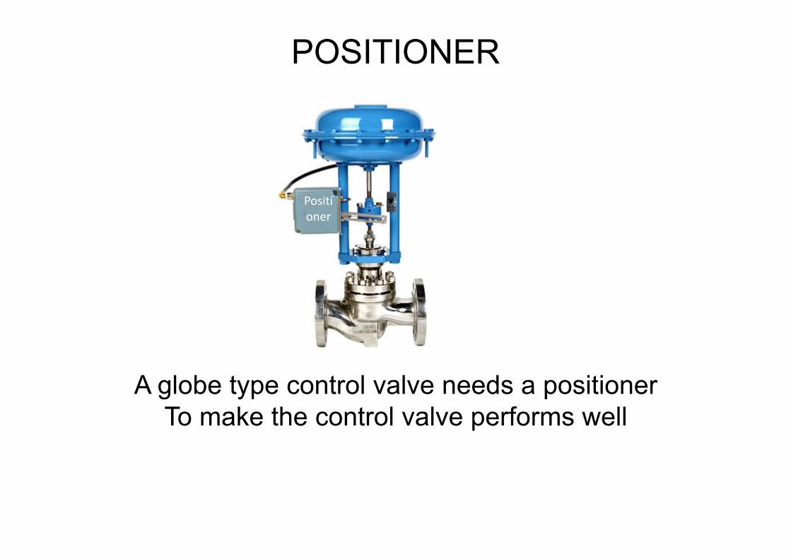
Positioner
A globe type control valve needs a positioner To make the control valve performs well
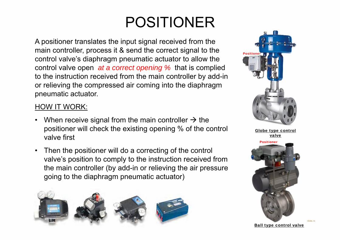
A positioner translates the input signal received from the main controller, process it & send the correct signal to the control valve’s diaphragm pneumatic actuator to allow the control valve open at a correct opening % that is complied to the instruction received from the main controller by add-in or relieving the compressed air coming into the diaphragm pneumatic actuator.
HOW IT WORK:
• When receive signal from the main controller the positioner will check the existing opening % of the control valve first
• Then the positioner will do a correcting of the control valve’s position to comply to the instruction received from the main controller (by add-in or relieving the air pressure going to the diaphragm pneumatic actuator)
![Presentation2 - Inkoinko.com.sg/image/data/CATALOG/Valve/LED tube with sensor... · 2017-12-22 · Microsoft PowerPoint - Presentation2 [Compatibility Mode] Author: Tony Created Date:](https://static.documents.pub/doc/80x56/5fb8250372c52911a25c2b59/presentation2-tube-with-sensor-2017-12-22-microsoft-powerpoint-presentation2.jpg)


