Japan International Cooperation Agency (JICA) Ministry of Industry, Mines and Energy (MIME) Electricity Authority of Cambodia (EAC) Kingdom of Cambodia GLOSSARY FOR SPECIFIC REQUIREMENTS OF ELECTRIC POWER TECHNICAL STANDARDS FOR HYDROPOWER FACILITIES (DRAFT) October 2009 Electric Power Development Co., Ltd. Tokyo, Japan The Chugoku Electric Power Co., Inc. Hiroshima, Japan
Transcript
Japan International Cooperation Agency (JICA)
Ministry of Industry, Mines and Energy (MIME) Electricity Authority of Cambodia (EAC) Kingdom of Cambodia
GLOSSARY FOR
SPECIFIC REQUIREMENTS OF
ELECTRIC POWER TECHNICAL STANDARDS
FOR HYDROPOWER FACILITIES
(DRAFT)
October 2009
Electric Power Development Co., Ltd. Tokyo, Japan
The Chugoku Electric Power Co., Inc. Hiroshima, Japan
Glossary for Hydropower Facilities
i
Table of Contents
Part 1 Civil Structures and Hydromechanical Equipment Air Intrusion.......................................................................................................................................1 Allowable Compressive Stress ..........................................................................................................1 Allowable Tensile Stress....................................................................................................................1 Anchor Block.....................................................................................................................................1 Area Affected by River Diversion .....................................................................................................1 Back-up Device..................................................................................................................................2 Buoyancy ...........................................................................................................................................2 Check Dam ........................................................................................................................................2 Circular Arc Method ..........................................................................................................................2 Coefficient of Permeability................................................................................................................3 Compressive Strength ........................................................................................................................3 Contraction Joint................................................................................................................................3 Cracking.............................................................................................................................................3 Dam....................................................................................................................................................3 Design Flood......................................................................................................................................3 Discharge facility ...............................................................................................................................3 Drainage Hole ....................................................................................................................................3 Dredging ............................................................................................................................................3 Dynamic Analysis ..............................................................................................................................4 Earth Pressure ....................................................................................................................................4 Earth-Embedded type (Penstock) ......................................................................................................4 Embankment Material........................................................................................................................4 Emergency Inspection........................................................................................................................4 Exceedance Probability......................................................................................................................5 Exposed type (Penstock)....................................................................................................................5 External water pressure......................................................................................................................5 Fault ...................................................................................................................................................5 Flood ..................................................................................................................................................5 Flood Water Level..............................................................................................................................6 Flushing .............................................................................................................................................6 Force Caused by Wind.......................................................................................................................6 Freeboard ...........................................................................................................................................6 Gallery ...............................................................................................................................................7 Gate....................................................................................................................................................7 Geologic Investigation.......................................................................................................................7
Glossary for Hydropower Facilities
ii
Grouting.............................................................................................................................................7 Head Tank ..........................................................................................................................................7 Headrace (Headrace Waterway).........................................................................................................7 Hoisted Gate Leaf ..............................................................................................................................8 Homogenous Fill Dam.......................................................................................................................8 Hydraulic Gradient ............................................................................................................................8 Hydraulic Model Test ........................................................................................................................8 Hydrodynamic Pressure .....................................................................................................................9 Hydrostatic Pressure ..........................................................................................................................9 Impervious Material...........................................................................................................................9 Impounding........................................................................................................................................9 In-situ Test .........................................................................................................................................9 Intake .................................................................................................................................................9 Intake Weir.......................................................................................................................................10 Internal Friction Coefficient (Angle) ...............................................................................................10 ISO...................................................................................................................................................10 Landslide..........................................................................................................................................10 Liquefaction .....................................................................................................................................10 Load Rejection.................................................................................................................................10 Low Water Level..............................................................................................................................10 Modulus of Deformation .................................................................................................................10 Mud Pressure ...................................................................................................................................10 Non-overflow Section......................................................................................................................11 Normal High Water Level................................................................................................................11 Outlet ...............................................................................................................................................11 Overflowing Water Surface .............................................................................................................11 Overtopping .....................................................................................................................................11 Overturning......................................................................................................................................11 Penstock...........................................................................................................................................11 Permeability Test .............................................................................................................................11 Pervious Material .............................................................................................................................11 Poisson's Ratio .................................................................................................................................11 Pore Pressure ...................................................................................................................................11 Power-drive Device .........................................................................................................................12 Powerhouse......................................................................................................................................12 Pressure Conduit ..............................................................................................................................12 Probable Maximum Flood (PMF)....................................................................................................12 Proportioning Strength.....................................................................................................................12
Glossary for Hydropower Facilities
iii
Rapid Drawdown .............................................................................................................................12 Re-regulation Pond ..........................................................................................................................12 Reservoir..........................................................................................................................................12 Rock-Embedded type (Penstock).....................................................................................................13 Saddle ..............................................................................................................................................13 Sand Flushing Gate..........................................................................................................................13 Screen Bar........................................................................................................................................13 Sedimentation ..................................................................................................................................13 Seepage Failure................................................................................................................................13 Seepage Line....................................................................................................................................14 Seismic Coefficient..........................................................................................................................14 Seismic Force...................................................................................................................................14 Self-weight.......................................................................................................................................14 Semi-pervious Material....................................................................................................................14 Settlement ........................................................................................................................................14 Settling Basin...................................................................................................................................15 Shear Strength..................................................................................................................................15 Sliding..............................................................................................................................................15 Solidifying .......................................................................................................................................15 Spillway ...........................................................................................................................................15 Spillway Gate...................................................................................................................................16 Static Analysis..................................................................................................................................16 Stop Log...........................................................................................................................................17 Storage Effect...................................................................................................................................17 Strength Test ....................................................................................................................................17 Surcharge Load ................................................................................................................................17 Surface Diaphragm Type Fill Dam ..................................................................................................17 Surge Tank .......................................................................................................................................17 Surging.............................................................................................................................................18 Tailrace (Tailrace Waterway) ...........................................................................................................18 Tailrace Bay .....................................................................................................................................18 Temperature load .............................................................................................................................18 Temporary Facilities for Construction .............................................................................................18 Transverse Joint ...............................................................................................................................19 Trash Rake .......................................................................................................................................19 Uplift................................................................................................................................................19 Valve ................................................................................................................................................19 Water Hammer Pressure ..................................................................................................................19
Glossary for Hydropower Facilities
iv
Waterstop .........................................................................................................................................19 Water-tightness ................................................................................................................................20 Waterway .........................................................................................................................................20 Weak Stratum...................................................................................................................................20 Zoned Type Fill Dam.......................................................................................................................20 Fig. 1 Reservoir Type....................................................................................................................21 Fig. 2 Run-of-river Type ...............................................................................................................21
Part 2 Electrical Facilities
1. General Terms Telecommunication Equipment for Electric Power System ............................................................22 Load Dispatching Center .................................................................................................................22
2. Physics Terms Capacitance......................................................................................................................................22 Electrical Conductivity ....................................................................................................................22 Electromagnetic Induction...............................................................................................................22 Electrostatic Induction .....................................................................................................................22 Illuminance ......................................................................................................................................22 Power Factor ....................................................................................................................................22 Reactive Power ................................................................................................................................23
3. Mechanical Terms Bypass Valve....................................................................................................................................23 Compressed Air Supply System ......................................................................................................23 Counter Weight ................................................................................................................................23 Counter Weight Closing Device ......................................................................................................23 Deflector of Pelton Turbine .............................................................................................................23 Francis Turbine ................................................................................................................................23 Guide Vane.......................................................................................................................................24 Pressure Oil Supply System.............................................................................................................24 Kaplan Turbine ................................................................................................................................24 Inlet Valve ........................................................................................................................................24 Maximum Momentary Pressure.......................................................................................................25 Momentary Pressure Variation.........................................................................................................25 Needle of Pelton Turbine .................................................................................................................25 Pelton Turbine..................................................................................................................................25 Safety Valve .....................................................................................................................................26 Self Closing Tendency of Guide Vanes or Main Inlet Valve............................................................26
Glossary for Hydropower Facilities
v
Steady State Runaway Speed...........................................................................................................26 Turbine.............................................................................................................................................26
Power-frequency Voltage.................................................................................................................30 Rectifier ...........................................................................................................................................30 Short Circuit Current .......................................................................................................................30 Solidly Earthed Neutral System.......................................................................................................30 Stabilizing Winding .........................................................................................................................30 Surge Arrester ..................................................................................................................................30 Synchronous Motor..........................................................................................................................30 Transformer......................................................................................................................................30 Voltage Transformer (VT)................................................................................................................31
5. Electricwires and Cables Terms Bare Wire .........................................................................................................................................31 Cable ................................................................................................................................................31 Connected Branch Electrical Line ...................................................................................................31 Guy Wire..........................................................................................................................................31 Insulators..........................................................................................................................................31 Mobile Cable ...................................................................................................................................31 Multi-core Cable ..............................................................................................................................31 Optical Fiber Cable..........................................................................................................................31 Overhead Lines ................................................................................................................................31 Sheath ..............................................................................................................................................32 Trolley Cable ...................................................................................................................................32 Trunk Line .......................................................................................................................................32 Underground Electrical Line............................................................................................................32 Wind Load .......................................................................................................................................32 Stranded Wire ..................................................................................................................................32 Crosslinked Polyethylene Cable (XLPE Cable) ..............................................................................32
Glossary for Hydropower Facilities Part 1
1
Part 1 Civil Structures and Hydromechanical Equipment
Air Intrusion
A phenomenon that air intrudes in headrace when water head in it is too small.
In this case, negative pressure will happen inside the conduit and it leads to some trouble such as break of lining concrete, fluctuation of output, etc.
S
VdAir intrusion as a voltex
Allowable Compressive Stress
An upper limit of compressive stress which may not break nor give harmful damage to a structure during its life span.
Allowable Tensile Stress
An upper limit of tensile stress which may not break nor give harmful damage to a structure during its life span.
Anchor Block
A structure for anchoring penstock.
Area Affected by River Diversion
River course between dam/intake weir and outlet where river flow is decreased due to taking of water for hydropower generation.
Glossary for Hydropower Facilities Part 1
2
Back-up Device
Standby power equipment used in case of emergency.
Buoyancy
Force acting upward on a floating object.
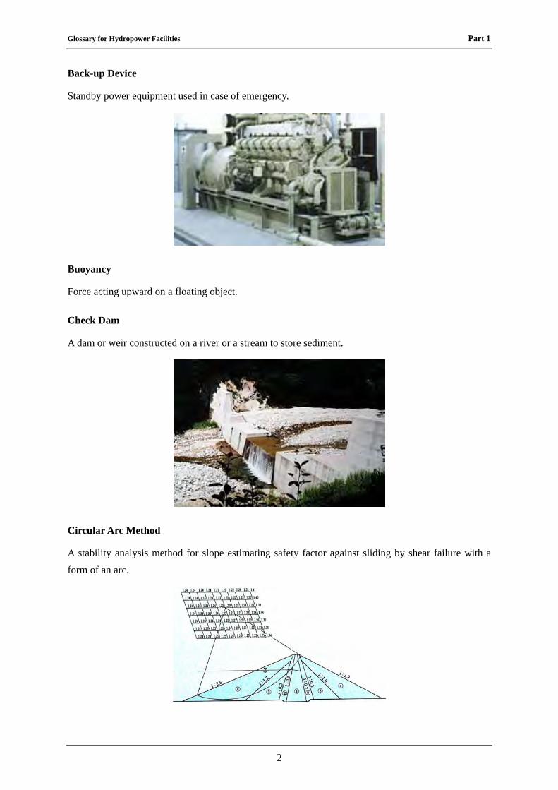
Check Dam
A dam or weir constructed on a river or a stream to store sediment.
Circular Arc Method
A stability analysis method for slope estimating safety factor against sliding by shear failure with a form of an arc.
Glossary for Hydropower Facilities Part 1
3
Coefficient of Permeability
Velocity of water in a unit area of porous material made by unit hydraulic gradient.
Compressive Strength
Ultimate resistance against compressive load.
Contraction Joint
A joint arranged to absorb contraction of concrete.
Cracking
A phenomenon that an object cracks inside it.
Dam
An artificial barrier across a stream, its foundations and affiliated facilities such as spillways constructed to store flowing water or divert it to intakes for power generation or other purpose.
See Fig. 1 (p.21).Design Flood
A flood discharge used for dam and spillway design.
Discharge facility
Facilities for discharging water downstream of dam for the purposes other than hydropower such as preservation of environment, plantations and fishes.
Drainage Hole
Holes installed in foundation of dam or other structures to decrease uplift force by releasing seepage water.
Dredging
Removing sediment out of a reservoir by excavating or pumping it.
Glossary for Hydropower Facilities Part 1
4
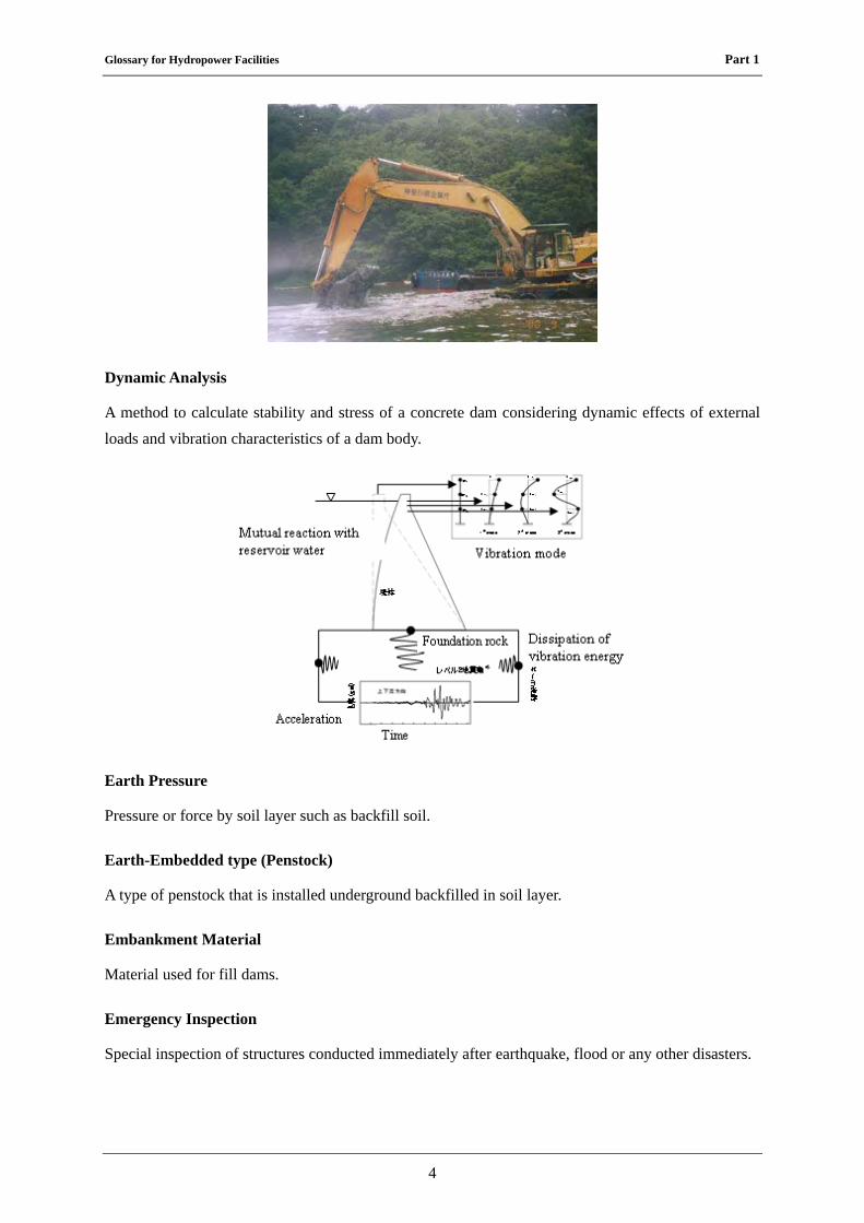
Dynamic Analysis
A method to calculate stability and stress of a concrete dam considering dynamic effects of external loads and vibration characteristics of a dam body.
Earth Pressure
Pressure or force by soil layer such as backfill soil.
Earth-Embedded type (Penstock)
A type of penstock that is installed underground backfilled in soil layer.
Embankment Material
Material used for fill dams.
Emergency Inspection
Special inspection of structures conducted immediately after earthquake, flood or any other disasters.
Glossary for Hydropower Facilities Part 1
5
Exceedance Probability
Probability that a phenomenon exceeding a certain criterion occurs.
Exposed type (Penstock)
A type of penstock that is installed above ground.
External water pressure
Water pressure that acts on outer surface of structures.
Fault
Discontinuity in the ground made by its movement caused by earthquake or orogeny.
Flood
A phenomenon that river flow increases by a heavy rain, thawing, etc.
Glossary for Hydropower Facilities Part 1
6
Flood Water Level
The highest elevation of reservoir water at discharging design flood.
Flushing
Removing sediment out of a reservoir using tractive force of water flow.
Force Caused by Wind
Force of wind or wind pressure acting on surface of an object.
Freeboard
A height between a dam crest and maximum design reservoir water level to be provided for non-overflow section to prevent it from overtopping.
Glossary for Hydropower Facilities Part 1
7
Gallery
A passage constructed in a dam to inspect a condition of a dam body, to release seepage water from dam foundation, to install measuring devices, etc.
Gate
A structure component mainly used for discharging water, regulating water and flushing debris/sedimentation.
Geologic Investigation
Investigation conducted by geologic method to examine characteristics and structure of bedrock.
Grouting
Injecting mixture of cement and water or mortar to cracks and spaces in bedrock of dam foundation, a gap of dam concrete, etc.
Head Tank
A facility that has a function to adjust the fluctuation and differences of discharge between in the waterway and in the penstock.
It also has a function to absorb raise of water pressure inside a headrace in shutting off the load.
It's installed between headrace waterway and penstock and applied only for the run-of-river type.
See Fig. 2 (p.21).
Headrace (Headrace Waterway)
A facility installed to convey water from the intake mouth to penstock.
Glossary for Hydropower Facilities Part 1
8
A gradient of the waterway is designed as gentle as possible to take the water head between the river and the waterway.
See Fig. 1 and Fig. 2 (p.21).
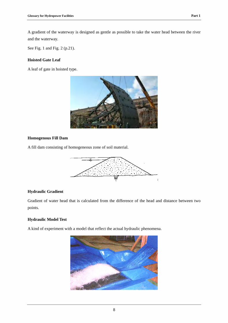
Hoisted Gate Leaf
A leaf of gate in hoisted type.
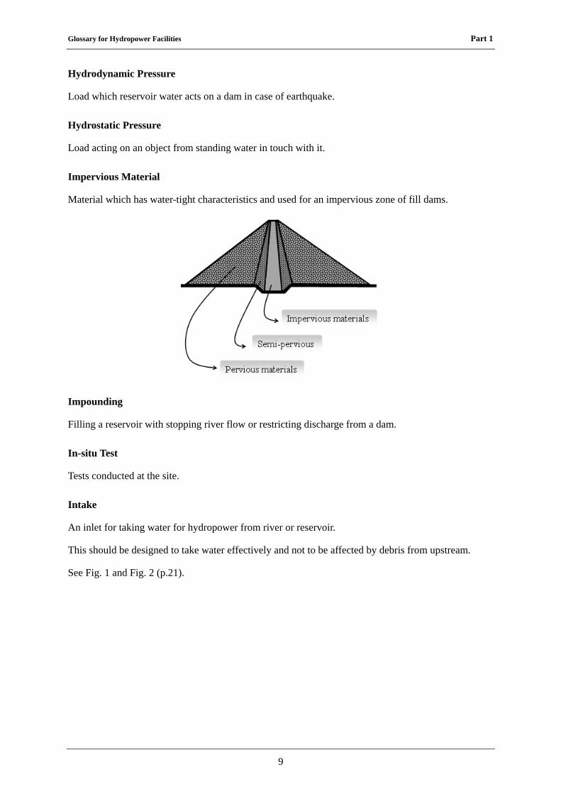
Homogenous Fill Dam
A fill dam consisting of homogeneous zone of soil material.
Hydraulic Gradient
Gradient of water head that is calculated from the difference of the head and distance between two points.
Hydraulic Model Test
A kind of experiment with a model that reflect the actual hydraulic phenomena.
Glossary for Hydropower Facilities Part 1
9
Hydrodynamic Pressure
Load which reservoir water acts on a dam in case of earthquake.
Hydrostatic Pressure
Load acting on an object from standing water in touch with it.
Impervious Material
Material which has water-tight characteristics and used for an impervious zone of fill dams.
Impounding
Filling a reservoir with stopping river flow or restricting discharge from a dam.
In-situ Test
Tests conducted at the site.
Intake
An inlet for taking water for hydropower from river or reservoir.
This should be designed to take water effectively and not to be affected by debris from upstream.
See Fig. 1 and Fig. 2 (p.21).
Glossary for Hydropower Facilities Part 1
10
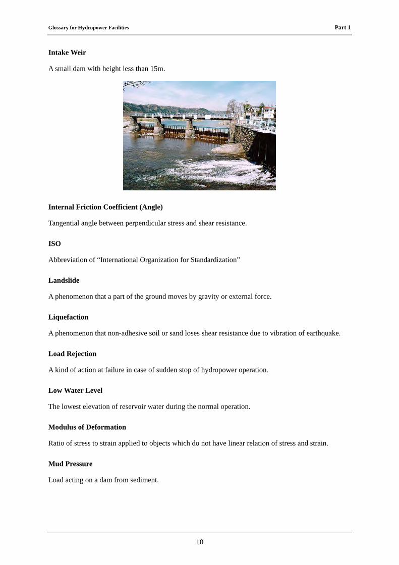
Intake Weir
A small dam with height less than 15m.
Internal Friction Coefficient (Angle)
Tangential angle between perpendicular stress and shear resistance.
ISO
Abbreviation of “International Organization for Standardization”
Landslide
A phenomenon that a part of the ground moves by gravity or external force.
Liquefaction
A phenomenon that non-adhesive soil or sand loses shear resistance due to vibration of earthquake.
Load Rejection
A kind of action at failure in case of sudden stop of hydropower operation.
Low Water Level
The lowest elevation of reservoir water during the normal operation.
Modulus of Deformation
Ratio of stress to strain applied to objects which do not have linear relation of stress and strain.
Mud Pressure
Load acting on a dam from sediment.
Glossary for Hydropower Facilities Part 1
11
Non-overflow Section
A part of a dam section where crest spillway does not exist and no overtopping is allowed.
Normal High Water Level
The highest elevation of reservoir water during the normal operation.
Outlet
A kind of mouth for releasing water after generation into river.
See Fig. 1 and Fig. 2 (p.21).
Overflowing Water Surface
Water surface line of overflowing through the spillway.
Overtopping
A phenomenon that water stored in a reservoir flows over a non-overflow section of a dam.
Overturning
A phenomenon that a structure overturns by external force.
Penstock
Structures installed to guide water directly from intakes, head tanks or surge tanks to hydraulic turbines consisting of pressure lining parts and their attachment facilities.
See Fig. 1 and Fig. 2 (p.21).
Permeability Test
A test to measure a coefficient of permeability.
Pervious Material
Material used for a pervious zone of fill dams.
See "Impervious Material".
Poisson's Ratio
A ratio of strain perpendicular to a load to that along a load.
Pore Pressure
Stress made by pore water.
Glossary for Hydropower Facilities Part 1
12
Power-drive Device
Powered device for operating equipment such as a gate mechanically.
Powerhouse
A building to install water turbines, generators and other equipment for power generation.
Pressure Conduit
A headrace/tailrace waterway of which inside is pressured.
This type of waterway is adopted in the pondage type and reservoir type hydropower project.
Probable Maximum Flood (PMF)
The flood that may occur under the theoretical combination of the most severe meteorological and hydrological conditions for rainfall. (PMP: Probable Maximum Precipitation)
Proportioning Strength
Strength of concrete to indicate design strength considering deviation.
Rapid Drawdown
A condition lowering reservoir water level rapidly. It may cause slip failure in a fill dam.
Re-regulation Pond
A pond constructed to regulate fluctuation of discharge for power generation from a powerhouse and to discharge constant flow downstream.
Reservoir
An artificial lake or pond appeared by construction of dam.
See Fig. 1 (p.21).
Glossary for Hydropower Facilities Part 1
13
Rock-Embedded type (Penstock)
A type of penstock that is installed underground in surrounded rock.
Saddle
One of the support structures for penstock applied to exposed type.
Sand Flushing Gate
A gate for flushing sedimentation sand in the bottom of hydro facilities such as intake weir.
Screen Bar
A facility for preventing suspending trash in the river from coming into intake.
Sedimentation
A phenomenon that sediment is stored in a reservoir.
Seepage Failure
A phenomenon that excessive amount of seepage water through a dam embankment or foundation stratum causes piping and brings about a dam breach.
Glossary for Hydropower Facilities Part 1
14
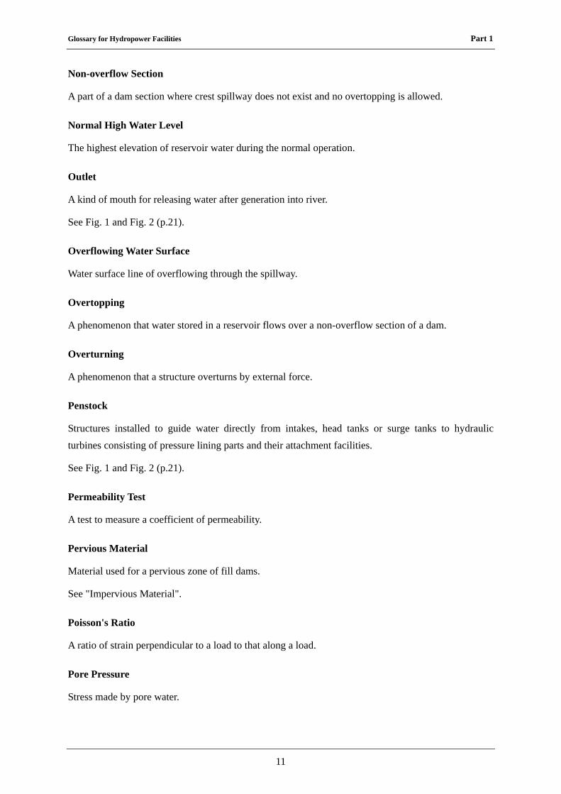
Seepage Line
A line of water surface formed in embankment when water infiltrates it.
Seismic Coefficient
Ratio of design seismic load to self-weight of a structure.
Seismic Force
Force induced by earthquake.
Self-weight
Own weight of a structure.
Semi-pervious Material
Material used for a semi-pervious zone of fill dams.
Settlement
A phenomenon that elevation of embankment or foundation goes down.
Glossary for Hydropower Facilities Part 1
15
Settling Basin
A facility for making suspended sands in the water descend to the bottom and preventing them from going into headrace waterway.
It's installed between intake and headrace waterway and applied only for the run-of-river type.
Shear Strength
Ultimate resistance against shear load.
Sliding
A phenomenon that a structure slides by external force.
Solidifying
Hardening of cement by hydration.
Spillway
An outlet or waterway for introducing spilling flood water to downstream of dam safely.
Glossary for Hydropower Facilities Part 1
16
Spillway Gate
A gate installed at the spillway.
Static Analysis
A method to calculate stability and stress of a structure from equilibrium of external loads and self-weight of a structure.
Glossary for Hydropower Facilities Part 1
17
Stop Log
Temporary shut down gate used in case of emergency or maintenance work under the dry condition.
Storage Effect
An effect that a reservoir with a capacity reduces peak discharge of an inflow flood hydrograph.
Strength Test
A test to measure ultimate resistance of material against failure.
Surcharge Load
Weight of an object on a structure.
Surface Diaphragm Type Fill Dam
A fill dam consisting of a dam body with pervious material and an impervious diaphragm installed on the upstream slope of the dam.
Surge Tank
A facility that has a function to adjust the fluctuation and differences of discharge between in the waterway and in the penstock.
It also has a function to absorb raise of water pressure inside a headrace in shutting off the load.
Glossary for Hydropower Facilities Part 1
18
It's installed between headrace waterway and penstock and applied only for the pondage type or reservoir type that install pressure type headrace waterway.
Surging
Swing of water level in a surge tank due to pressure increase or decrease by load rejection or rapid load variation.
Tailrace (Tailrace Waterway)
A waterway that is installed between draft tube and outlet.
It's a waterway for conducting water after generation into river.
See Fig. 1 (p.21).
Tailrace Bay
A kind of bay that is installed between daft tube and tailrace waterway.
This has a function for making water after generation stabilized by setting wide pool.
Temperature load
Load acting in facilities itself according to expansion or shrinkage of material due to change of temperature.
Temporary Facilities for Construction
Temporary facilities that are installed only in construction period and removed after construction.
Glossary for Hydropower Facilities Part 1
19
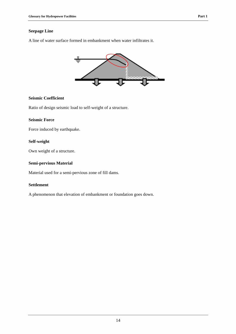
Transverse Joint
A contraction joint in concrete structure arranged perpendicular to a dam axis.
Trash Rake
Equipment for removing trash trapped in front of screen bar.
Uplift
Upward pressure of seepage water through dam foundation acting at the bottom of dam.
Valve
A device to regulate flow of fluid by opening, closing or partially obstructing various passage way.
Water Hammer Pressure
A pressure surge or wave resulting when a fluid in motion is forced to stop or change direction suddenly.
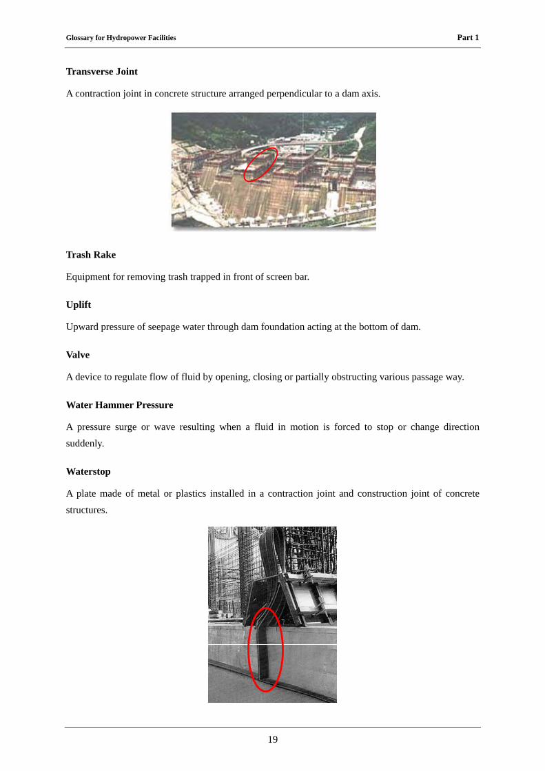
Waterstop
A plate made of metal or plastics installed in a contraction joint and construction joint of concrete structures.
Glossary for Hydropower Facilities Part 1
20
Water-tightness
Characteristics of material or structure how it resists against water by infiltration through it.
Waterway
A general term of channels and auxiliaries including gates and valves that take flowing or stored water, convey it to hydro-turbines, and discharge it into a river and so on for power generation.
Weak Stratum
A part of the ground deteriorated by some reasons.
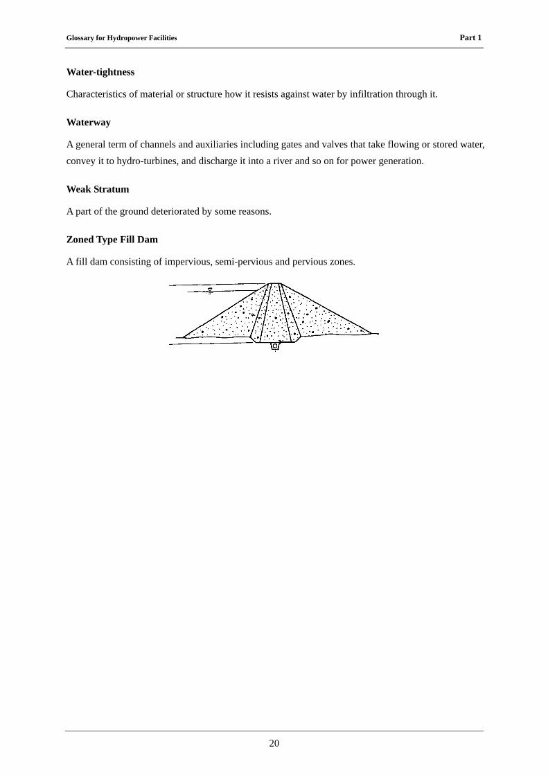
Zoned Type Fill Dam
A fill dam consisting of impervious, semi-pervious and pervious zones.
Glossary for Hydropower Facilities Part 1
21
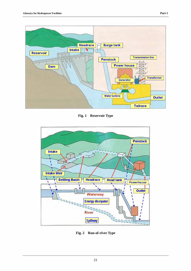
Fig. 1 Reservoir Type
Fig. 2 Run-of-river Type
Spillway
Energy dissipator
Glossary for Hydropower Facilities Part 2
22
Part 2 Electrical Facilities
1. General Terms
Telecommunication Equipment for Electric Power System
Telecommunication equipment which is exclusively used for maintaining the electrical facilities.
Load Dispatching Center
The place which control the power stations, substations, switching stations, distribution lines and transmission lines.
2. Physics Terms
Capacitance
Amount of electric charge stored for a given electric potential.
Electrical Conductivity
Degree of a material’s ability to conduct an electric current.
Electromagnetic Induction
Connecting the electromotive force with relation to the magnetic flux through the circuit. Faraday’s law of induction describes a basic law of electromagnetism.
Electrostatic Induction
A redistribution of electrical charge in an object, caused by the influence of nearby charges.
Illuminance
In photometry, illuminance is the total luminous flux incident on a surface, per unit area. It is a measure of the intensity of the incident light, wavelength-weighted by the luminosity function to correlate with human brightness perception. Similarly, luminous emittance is the luminous flux per unit area emitted from a surface. Luminous emittance is also known as luminous existence.
In SI derived units, these are both measured in lux (lx) or lumens per square meter (cd·sr·m−2). In the CGS system, the unit of illuminance is the phot. One phot is equal to 10,000 lux.
Power Factor
Under periodic conditions, ratio of the absolute value of the active power to the apparent power.
Glossary for Hydropower Facilities Part 2
23
Reactive Power
Non-active power for a linear two-terminal element or two-terminal circuit.
3. Mechanical Terms
Bypass Valve
A valve for pipe providing an auxiliary passage for main water way. Bypass valve shall open before operation of main inlet valve to equalize a pressure of penstock and spiral casing.
Compressed Air Supply System
A system which supplies compressed air for oil supply system and breaks of unit. In case of condenser operation, air is also used for depressing water level in draft tube liner. Normally system consists of air compressor, air tanks, pressure gauge, relays and so on.
Counter Weight
A weight equal to another; counterbalance.
Counter Weight Closing Device
Guide vanes or main inlet valve closing by means of the force of counter weight with single action servomotor.
Deflector of Pelton Turbine
Device of Pelton turbine controlled by the regulator to deflect the water jet away from the buckets. Normally the deflectors are used at emergency cases.
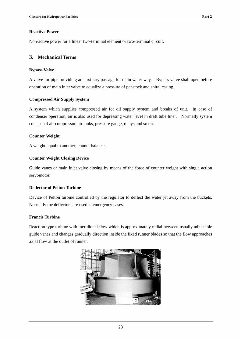
Francis Turbine
Reaction type turbine with meridional flow which is approximately radial between usually adjustable guide vanes and changes gradually direction inside the fixed runner blades so that the flow approaches axial flow at the outlet of runner.
Glossary for Hydropower Facilities Part 2
24
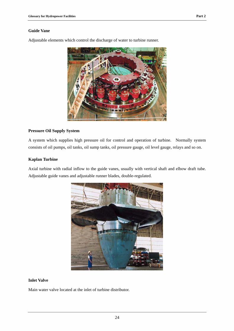
Guide Vane
Adjustable elements which control the discharge of water to turbine runner.
Pressure Oil Supply System
A system which supplies high pressure oil for control and operation of turbine. Normally system consists of oil pumps, oil tanks, oil sump tanks, oil pressure gauge, oil level gauge, relays and so on.
Kaplan Turbine
Axial turbine with radial inflow to the guide vanes, usually with vertical shaft and elbow draft tube. Adjustable guide vanes and adjustable runner blades, double-regulated.
Inlet Valve
Main water valve located at the inlet of turbine distributor.
Glossary for Hydropower Facilities Part 2
25
Maximum Momentary Pressure
Maximum momentary pressure is maximum water pressure in case of sudden change of inflow water to turbine.
Momentary Pressure Variation
Difference between maximum water pressure at test and static head of turbine center at stand still condition is called momentary pressure variation. Ratio of momentary pressure value to static head is also called momentary pressure variation.
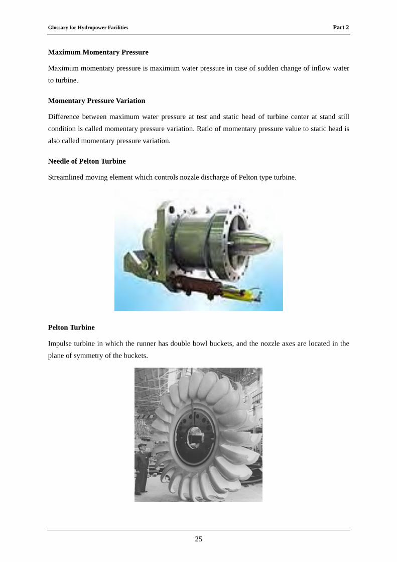
Needle of Pelton Turbine
Streamlined moving element which controls nozzle discharge of Pelton type turbine.
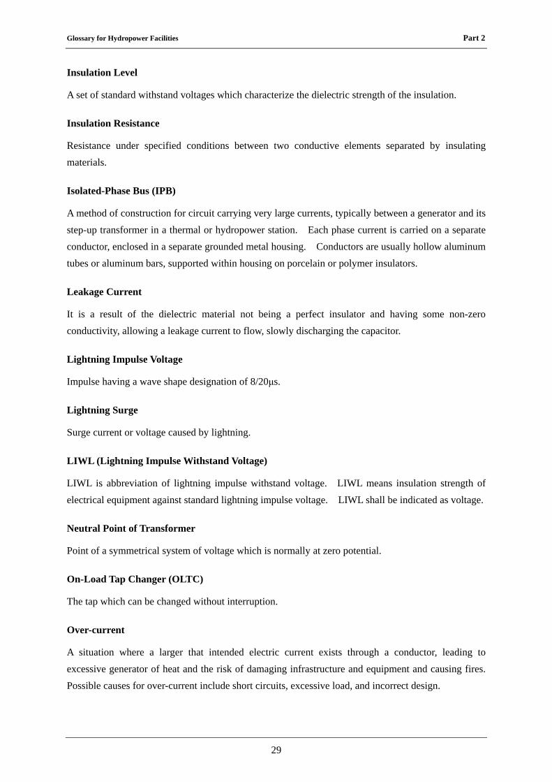
Pelton Turbine
Impulse turbine in which the runner has double bowl buckets, and the nozzle axes are located in the plane of symmetry of the buckets.
Glossary for Hydropower Facilities Part 2
26
Safety Valve
A safety valve is a valve mechanism for the automatic release of a gas from a boiler, pressure vessel, or other system when the pressure or temperature exceeds preset limits.
Self Closing Tendency of Guide Vanes or Main Inlet Valve
Characteristic of guide vanes or inlet valve to close automatically by means of eccentric construction with water force.
Steady State Runaway Speed
Possible maximum rotating speed of turbine with no-load at some head with some opening of guide vane, runner vane or needle.
Turbine
Prime mover for transforming hydraulic energy into mechanical energy. The term does not include the inlet or outlet valves nor the associated generator or regulator.
4. Electrical Terms
Automatic Voltage Regulator (AVR)
AVR is an abbreviation for Automatic Voltage Regulator. It is important part in synchronous generators. It controls the output voltage of the generator by controlling its excitation current. Thus it can control the output reactive power of the generator.
Battery
Combination of one or more electrochemical galvanic cells which store chemical energy that can be converted into electric potential energy, creating electricity.
Bus-bar
Low impedance conductor to which several electric circuits can be separately connected.
Capacitor Voltage Transformer (CVT)
A capacitor voltage transformer is one kind of VT. In its most basic form the device consists of three (3) parts: two (2) capacitors across which the voltage signal is split, an inductive element used to tune the device to the supply frequency and a transformer used to isolate and further step down the voltage for the instrumentation or protective relay.
Glossary for Hydropower Facilities Part 2
27
Circuit Breaker
Automatically-operated electrical switch designed to protect an electrical circuit from damage caused by overload or short circuit.
Contact Preventing Plate
Kind of earthed metal plate which is placed between medium and low voltage winding to prevent the mixture of them.
Current Transformer (CT)
A type of instrument transformer designed to provide a current in its secondary winding proportional to the alternating current flowing in its primary. They are commonly used in metering and protective relaying in the electrical power industry where they facilitate the safe measurement of large currents, often in the presence of high voltages. The current transformer safely isolates measurement and control circuitry from the high voltages typically present on the circuit.
Dielectric Breakdown
A reference to the breakdown of the insulation of an electrical wire or other electrical component. Such breakdown usually results in short circuit or blown fuse. This occurs at the breakdown voltage. The breakdown is often associated with the failure of solid or liquid insulating materials used in high voltages transformers or capacitors in the electricity distribution grid. The breakdown can also occur across the strings of insulators that suspend overhead power lines, within underground power cables, or lines arcing to nearby branch of trees.
Dielectric Strength
Electric field strength which can withstand intrinsically without breaking down without experiencing failure of its insulating properties.
Disconnecting Switch
Switches are safety devices to open or to close a circuit when there is no current through them. They are used to isolate a part of a circuit, a machine, a part of an overhead line or an underground line. In principle, disconnecting switches do not have to interrupt currents, as they are designed for use on de-energized circuits.
Earth Fault
Insulation fault between one phase conductor and earth only.
Glossary for Hydropower Facilities Part 2
28
Earth Fault Circuit Breaker
Circuit breaker which is automatic device for stopping the earth fault current flow in an electric circuit as a safety to prevent electrical shock.
Enclosed Fuse
Plug fuse or cartridge fuse, which has metal or insulated material housing, having capacity to shut-off rated current by melting material without arc nor gas safety.
Expulsion Fuse
Fuse of which operation is accomplished by expulsion of gases produced by the arc.
Fuel Cell
Cell which produces an electric current directly from a chemical reaction.
Gas Insulated Equipment
Electrical equipments whose conductors are contained in an enclosure and insulated with a compressed insulated gas. Normally sulfur hexafluoride (SF6) gas is applied.
Generator
Machine which converts mechanical energy into electrical energy.
Ground or Earth
Direct physical connection to earth.
Idle Winding
Winding which is not used normal operating conditions.
Induction Motor
A type of asynchronous AC motor where power is supplied to the rotating device by means of electromagnetic induction.
Instrument Transformers
Transformer intended to transmit an information signal to measuring instruments, meters and protective and control device.
Insulation Oil
Normally mineral oils, as delivered, intended for use in transformers, switchgear and similar electrical equipment in which oil is required as an insurant or for heat transfer.
Glossary for Hydropower Facilities Part 2
29
Insulation Level
A set of standard withstand voltages which characterize the dielectric strength of the insulation.
Insulation Resistance
Resistance under specified conditions between two conductive elements separated by insulating materials.
Isolated-Phase Bus (IPB)
A method of construction for circuit carrying very large currents, typically between a generator and its step-up transformer in a thermal or hydropower station. Each phase current is carried on a separate conductor, enclosed in a separate grounded metal housing. Conductors are usually hollow aluminum tubes or aluminum bars, supported within housing on porcelain or polymer insulators.
Leakage Current
It is a result of the dielectric material not being a perfect insulator and having some non-zero conductivity, allowing a leakage current to flow, slowly discharging the capacitor.
Lightning Impulse Voltage
Impulse having a wave shape designation of 8/20μs.
Lightning Surge
Surge current or voltage caused by lightning.
LIWL (Lightning Impulse Withstand Voltage)
LIWL is abbreviation of lightning impulse withstand voltage. LIWL means insulation strength of electrical equipment against standard lightning impulse voltage. LIWL shall be indicated as voltage.
Neutral Point of Transformer
Point of a symmetrical system of voltage which is normally at zero potential.
On-Load Tap Changer (OLTC)
The tap which can be changed without interruption.
Over-current
A situation where a larger that intended electric current exists through a conductor, leading to excessive generator of heat and the risk of damaging infrastructure and equipment and causing fires. Possible causes for over-current include short circuits, excessive load, and incorrect design.
Glossary for Hydropower Facilities Part 2
30
Over-current Protective Device
Circuit breaker or fuse which breaks the over current in an electric circuit as a safety.
Overload Protective Device
Device intended to operate in the event of overload on the protected section.
Polychlorinated Biphenyl (PCB)
High toxicity organic compounds which were used as coolants and insulating fluids for transformers and capacitors.
Power-frequency Voltage
Voltage at rated frequency of the power system.
Rectifier
Electrical device which rectifies an alternating current into a direct current.
Short Circuit Current
Current flowing at a given point of a network resulting from a short circuit at another point of this network.
Solidly Earthed Neutral System
System whose neutral point is physically earthed directly
Stabilizing Winding
Supplementary delta-connected winding, especially provided on star-star or star-zigzag connected transformers to decrease the zero-sequence impedance of the star-connected winding.
Surge Arrester
An appliance designed to protect electrical devices from voltage spikes. The surge arrester attempts to regulate the voltage supplied to an electric device by either blocking or by shorting to ground voltages above a safe threshold.
Synchronous Motor
Synchronous machine which converts electrical energy into mechanical energy.
Transformer
Equipment which transfers electrical energy from one circuit to another through inductive coupled electrical conductors.
Glossary for Hydropower Facilities Part 2
31
Voltage Transformer (VT)
A transformer used in power system to step down some voltage signals and provide low voltage signals either for measurement or to operate a protective relay.
5. Electricwires and Cables Terms
Bare Wire
Conductor which is not covered or insulated any insulation.
Cable
One or more strands bound together. Electrical cable may contain one or more metal conductors, which may be individually insulated or covered.
Connected Branch Electrical Line
Branch electrical line which is connected from service point to other service point not through any supporting structure.
Guy Wire
Steel wire rope or rod, working under tension, connecting a point of a support to a separate anchor, or connecting two points of the support.
Insulators
Apparatus intended for electrical insulation and mechanical fixing of equipment or conductors which are subject to potential differences.
Mobile Cable
Cable which is movable from one place to the other.
Multi-core Cable
Kind of electrical cable which has multi cores.
Optical Fiber Cable
Cable in which filament-shaped waveguide made of dielectric materials for guiding optical waves.
Overhead Lines
Metallic conductors which are used to transmit electrical energy to electrical facilities at a distance from the energy supply point.
Glossary for Hydropower Facilities Part 2
32
Sheath
Uniform and continuous tubular covering made of conductive or insulating material.
Trolley Cable
Electric power supply cable which is being contacted to trolley directly supplying for such as trams, trolleybus, train or crane.
Trunk Line
Main line for the electrical line.
Underground Electrical Line
Electric line with insulated conductors buried directly in the ground or laid in cable ducts, pipes etc.
Wind Load
A load resulting from perpendicular wind pressure applied to any element of the overhead line, with or without ice loading.
Stranded Wire
One of the wires of a stranded conductor.
Crosslinked Polyethylene Cable (XLPE Cable)
Cable which has sheath of cross-linked polyethylene.