Operation Manual and Data Sheet
www.intermountainelectronics.com (877) 544-2291 / (435) 637-7160
US Pat. Numbers: 9,124,089, 9,172,234, 9,197,055
Continuity Ground Monitors with
Ground Lock Technology
GLT-500 / GLT-500-1 GLT-AT500 / GLT-AT500-1
Copyright © 2016. All rights reserved.
Important Notice
This document contains information intended to aid in the proper installation, operation, and mainte-
nance of the product described. Although this information will prove useful to the properly trained and
qualified user, it is not practical to cover every possible situation, installation contingency, or other de-
tail.
It is imperative that proper engineering and techniques are adhered to in the installation, operation,
and maintenance of this product. It is the responsibility of the user to ensure that any system utilizing this
product is safe, and that all personnel involved with the selection, installation, maintenance, and use of
this product are properly qualified. This product must not be used in situations where its ratings are ex-
ceeded.
While every effort has been made to make sure the information in this document is accurate, IE cannot
guarantee that there are no errors. Users of this product should independently verify any aspects of the
product’s design or performance that are critical to their application, and in particular, any aspects
that may affect the safety of the overall system or installation.
Product design and specifications may change without notice.
www.intermountainelectronics.com
Note:
Any required repairs to the GLT-500, GLT-500-1, GLT-AT500 or GLT-AT500-1 should be performed at Inter-mountain Electronics, Inc., where the units can be properly re-calibrated. Calibrating these products requires specialized equipment, and cannot be performed outside of the IE factory.
Price UT Facility
Protected under US patents 9,124,089, 9,172,234, 9,197,055
Tables and Figures:
3…….. Figure 1: Controls and Connections
5…….. Figure 2: Typical Installation Schematic, GLT-500 / GLT-500-1
6…….. Figure 2: Typical Installation Schematic, GLT-AT500 / GLT-AT500-1
7…….. Figure 3: Typical System Block Diagram
10.……Figure 4: Physical Dimensions, GLT-500 / GLT-AT500
11…… Figure 5: Physical Dimensions, GLT-500-1 / GLT-AT500-1
12…… Figure 6: Physical Dimensions, Pilot Wire Device (PWD)
5…….. Table 1: Connector Pin-Out, GLT-500 / GLT-500-1
6…….. Table 1: Connector Pin-Out, GLT-AT500 / GLT-AT500-1
9…….. Table 2: Required GWDs and CTs
Table of Contents:
1…….. I: General Information
3…….. II: Features, Controls and Connections
7…….. III: Operation and Specifications
(877) 544-2291 / (435) 637-7160
www.intermountainelectronics.com
1
I: GENERAL INFORMATION
GLT-500
GLT-500-1
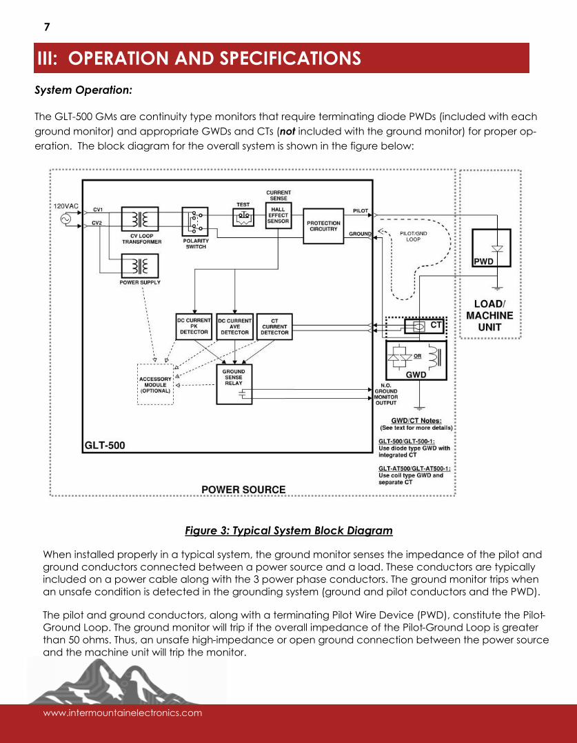
The GLT-500 family of products are state-of-the-art, fail-safe, continuity ground monitors (GMs) for use in
low, medium and high voltage applications. These ground monitors feature patented Ground Lock
Technology™.
The GLT-500 GMs are approved by MSHA, and, unlike most ground monitors in use today, meet all cur-
rent MSHA testing standards (CFR 30 Parts 75, 77, MSHA documents ASTP 2135 and ACRI 2003).
(877) 544-2291 / (435) 637-7160
2
Ground Lock Technology™ (GLT): Revolutionary technology that precisely monitors ground currents much more accurately and reliably than old-school methods used in other continuity ground monitors.
The GLT-500 family includes four models for use in different mechanical configurations, and with differ-
ent Ground Wire Devices (GWDs):
The GLT-500 and GLT-AT500 are full chassis designs. These are panel mounted and feature fully en-
closed electronics. The GLT-500-1 and GLT-AT500-1 are open frame units designed to be rear mount-
ed.
The “AT500” versions (GLT-AT500 and GLT-AT-500-1) are intended to be used with coil-type GWDs, while
the GLT-500 and GLT-500-1 are to be used with anti-parallel diode-type GWDs.
The full chassis versions are mechanically and electrically compatible (pin-to-pin) with popular GMs
that have been in use for several decades, so an upgrade is as simple as removing the old unit, and
installing the GLT-500/GLT-AT500 in its place. The open frame versions are also electrically compatible
(pin-to-pin) with similar existing products, but have different mechanical profiles. The full chassis and
open frame units are electronically identical, except that the full chassis versions have an extra latch-
ing indicator breaker feature (see below).
All GLT-500 GMs are designed to be used in power systems with system voltages of up to 5kV.
Continuity ground monitors of this type operate by applying an AC test signal through a pilot conduc-
tor to the ground conductor (the pilot/ground loop), and then sensing the ground current produced
by this test signal.
Typical installations for the GLT-500 monitors include the monitor itself and a terminating Pilot Wire Di-
ode (PWD), along with a suitable Ground Wire Device (GWD) and current transformer (which may or
may not be integrated with the GWD).
The PWD for the GLT-500 has been specially designed by Intermountain Electronics, and is included
with the ground monitor.
The GLT-500 GMs have been designed to work with a variety of coil and diode type GWDs. Generally,
when using a diode type GWD (with GLT-500, GLT-500-1), the current transformer will be integrated
with the GWD. However, when using a coil-type GWD (with GLT-AT500, GLT-AT500-1), the current trans-
former is not integrated into the GWD, and must be procured and mounted separately.
Depending on the regulations for the location and application, MSHA approved GWDs may or may
not be required. For non-MSHA applications, IE GWDs are recommended (see below). Where MSHA
approvals are required, several commercially available MSHA approved GWDs are available (please
contact IE for recommendations).
Every GLT-500 monitor includes an exclusive accessory port. This port allows accessory modules
(available separately) to greatly enhance connectivity and signal monitoring capabilities.
In addition to providing a ground monitoring function, the GLT-500 GMs can also be used to provide
fail-safe control of machine start and stop operations. These two functions can be performed simulta-
neously.
www.intermountainelectronics.com
3
II: FEATURES, CONTROLS AND CONNECTIONS
Key features of the GLT-500 family of monitors include:
GLT Technology™ for improved ground monitoring and reliability
Rugged mechanical construction, sealed from the elements (full chassis versions)
MSHA approved for LV/MV operation in installations requiring MSHA certification
Fail-safe design
Modern electronic design, utilizing up-to-date, reliable components
Accessory port for enhanced connectivity/expandability
Easy upgrade: GLT-500s are fully reverse compatible with old GMs from other manufacturers
Every GLT-500 is designed for use in power systems operating at up to 5 kV
Available in full chassis and open frame versions.
The front and rear panels for the GLT-500 monitors are shown in figure 1 below.
2
4
1
3
3
1
6
7
4
5
7
6
5
7
Figure 1: Controls and Connections
GLT-500/-AT500 (left) and GLT-500-1/-AT500-1 (right)
(877) 544-2291 / (435) 637-7160
4
1) Pilot Light / Trip Indicator
2) Latching Trip Indicator Breaker (GLT-500 / GLT-AT500 only)
3) Polarity Switch
4) Test Push Button
5) Accessory Port
6) I/O Connector
7) Mounting locations
The Pilot Light/Trip Indicator is a dual-color indicator that is green during normal operation, and red
when the GM is tripped (indicating a broken or high-impedance ground).
The Latching Trip Indicator Breaker (GLT-500 / GLT-AT500 only) trips any time the ground monitor trips,
and it stays tripped until manually reset. The purpose of this indication is to help identify intermittent
problems with the ground conductors.
The polarity switch allows the user to select the polarity of the AC test signal going through the pilot/
ground loop. The purpose of this control is to help prevent nuisance tripping that could occur in some
instances if large current surges are induced in the loop. These surges may be created when certain
equipment, like a large motor, is turned on. Reversing the polarity of the test signal generally solves this
problem.
The test button (mounted on the front panel) simulates a high impedance ground condition by placing
a resistance into the pilot-ground loop. When this switch is pressed, the ground monitor trips, and this
trip is registered by the trip indicators (light and breaker).
The accessory port allows Intermountain Electronics expansion/accessory modules (available separate-
ly) to be installed in the GLT-500 to dramatically increase interconnectivity and signal monitoring capa-
bilities. For example, adding the expansion module with D-Sub connector and barrier strip (IE Part Num-
ber 1100-7100) provides additional relay contacts (NC), and makes other signals available, including
analog signals for externally monitoring ground currents and detector levels. Refer to the manuals for
the IE expansion modules for more information.
Figure 2 (below) includes the installation schematic diagrams for the GLT-500 / GLT-500-1 (on the left)
and the GLT-AT500 / GLT-AT500-1 (on the right).
www.intermountainelectronics.com
7
III: OPERATION AND SPECIFICATIONS
System Operation:
The GLT-500 GMs are continuity type monitors that require terminating diode PWDs (included with each
ground monitor) and appropriate GWDs and CTs (not included with the ground monitor) for proper op-
eration. The block diagram for the overall system is shown in the figure below:
Figure 3: Typical System Block Diagram
When installed properly in a typical system, the ground monitor senses the impedance of the pilot and
ground conductors connected between a power source and a load. These conductors are typically
included on a power cable along with the 3 power phase conductors. The ground monitor trips when
an unsafe condition is detected in the grounding system (ground and pilot conductors and the PWD).
The pilot and ground conductors, along with a terminating Pilot Wire Device (PWD), constitute the Pilot-
Ground Loop. The ground monitor will trip if the overall impedance of the Pilot-Ground Loop is greater
than 50 ohms. Thus, an unsafe high-impedance or open ground connection between the power source
and the machine unit will trip the monitor.
(877) 544-2291 / (435) 637-7160
8
The monitor will also trip if the Pilot and Ground wires short together (thus bypassing the PWD). This is im-
portant, because if the Pilot and Ground were shorted together, an open ground conductor might not
be detected, and an unsafe condition would result.
This type of ground monitor system also has the capability of discriminating between a safe ground
conductor, and an unreliable “parallel” ground path (e.g. through the earth). Without this function, a
parallel path could mask a broken or poor ground conductor.
In addition, the GLT-500 GMs will detect, and trip on, any of these conditions: Faulty or missing PWD,
missing or inadequate power supply (Control Voltage), and excess detected stray DC currents.
The GLT-500 GMs are a fail-safe design, so any internal circuit failure that could cause improper opera-
tion will cause a trip.
Differences: GLT-500 / GLT-500-1 vs. GLT-AT500 / GLT-AT500-1:
The GLT-500 / GLT-500-1 models and the corresponding GLT-AT500 /GLT-AT500-1 models are identical in
features and operation. However, the GLT-500 models are designed to work with diode type GWDs,
whereas the GLT-AT500 models are designed to work with saturable coil type GWDs.
It is important to use the models in the GLT family with the correct GWD types to ensure that calibrations
are accurate. Otherwise, the, the GLT could trip at an impedance level that is too low (more likely to
nuisance trip), or too high (greater than 50 ohms).
In applications requiring MSHA approval, the GLT GMs must be correctly matched with the correct
GWDs in order to be compliant. Refer to Table 2 for details about GWD selection.
Under normal operating conditions, the GWD presents a high impedance between the load ground
conductor and the source ground. However, in the case of large ground currents, such as may occur
during a ground fault, the GWD virtually shorts the grounds together for safety. Both diode and coil
type GWDs perform this function in a similar manner.
Theory of operation:
The CV Loop Transformer produces a constant voltage, 60Hz AC test signal from the 120V control volt-
age. This test signal may be inverted with the Polarity Switch (switching polarity is often useful in prevent-
ing nuisance trips), and then the test signal is applied to the Pilot/Ground Loop. At the machine end of
the Pilot/Ground loop, the PWD rectifies the test signal, so current only flows on one-half of the AC wave
of the test signal.
The resulting DC test current through the Pilot/Ground Loop is measured with two different sensors: a hall
-effect sensor inside the GM, and an external CT transformer. The CT transformer may be integrated
with a diode type GWD, or it may be a separate unit used with a coil type GWD.
The hall-effect sensor output is processed by two different detector circuits. Both circuits measure DC
current (only). One circuit measures peak current, while the other measures average current.
As long as the PWD is working properly, the Pilot/Ground loop current will be half-wave rectified, and
thus unfiltered DC. If the PWD is faulty or bypassed, the current will be symmetrical AC, with very low DC
content. The peak detector will sense this low DC current content, and will trip (de- energize) the
Ground Sense Relay.
www.intermountainelectronics.com
9
The average current detector senses stray DC currents that could occur if a fault existed between an
external DC source and the Pilot/Ground loop. If large enough, these stray DC currents could interfere
with the test current being measured by the DC peak detector. For this reason, the average current de-
tector will trip the Ground Sense Relay if large average DC currents are detected.
Together, the peak and average current detector circuits form a kind of “window comparator” with the
GM tripping if peak current is too low, or average current is too high.
The Pilot/Ground loop test current is also sensed with the external CT. The CT Current Detector circuit
monitors the level of this current, and it trips the Ground Sense Relay if the current is too low. The pur-
pose of this CT and detector is to ensure that any currents being sensed by the ground monitor have
actually come through the Ground conductor, and not from some parallel grounding path, such as
through the earth. Without this detector, such a parallel path could prevent a broken ground conduc-
tor from being detected.
A test button on the GLT-500 simulates a high impedance ground condition by inserting a resistor in se-
ries with the Ground/Pilot loop. Pushing this button results in a ground monitor trip, thus verifying proper
operation.
The GLT-500 includes an accessory port. Intermountain Electronics offers optional accessory modules
that can be installed in this port to allow access to additional signals not included on the main 8-pin
connector. For example, available signals include ground monitor relay NC connections and analog
signals for ground current, ground current detector levels, etc.
Specifications:
Control Voltage: 120VAC, 60 Hz. Nominal power draw is 25W
Impedance Trip Level: No greater than 50 ohms (45 ohms nominal)
System Voltage: Up to 5kV
Required PWD: Intermountain Electronics PN: 1020-0051
Recommended GWD/CT: See table below
Model Recommended GWD / CT
(MSHA approval not required)
Recommended GWD / CT
(MSHA approval required)
GLT-500
GLT-500-1
1100-6020 GWD with Integrated
Current Transformer
Contact IE for recommendations
GLT-AT500
GLT-AT500-1
Current Transformer: IE PN 2000-0308
GWD: IE PN 1100-6010
Current Transformer: IE PN 2000-0308
GWD: Contact IE for recommendations
Table 2: Required GWDs and CTs
(877) 544-2291 / (435) 637-7160
10
Physical Characteristics:
Weight: GLT-500 / GLT-AT500: 5.9 lbs / 2.7 kG
GLT-500-1 / GLT-AT-500-1: 4.7 lbs / 2.1 kG
Dimensions:
Figure 4: Physical Dimensions, GLT-500 / GLT-AT500
2000-0416-F
Contact Intermountain Electronics:
Phone: (435) 637-7160
Fax: (435) 637-9601
Web: www.intermountainelectronics.com
E-mail: [email protected]
Mining |Oil & Gas |Tunneling | Power Generation
Utilities | Government |Municipalities
Price, Utah | Denver, Colorado | South Point, Ohio | Centralia, Illinois
Hermosillo Mexico | Washington, Pennsylvania