+ All Categories
Home > Documents > GLUCOCEREBROSIDASE DERIVATIVES AS INHIBITORS OF HUMAN ... · SYNTHESIS AND TESTING OF ISOFAGOMINE...

GLUCOCEREBROSIDASE DERIVATIVES AS INHIBITORS OF HUMAN ... · SYNTHESIS AND TESTING OF ISOFAGOMINE...

Date post: 23-Apr-2018
Category:
Upload: lebao
View: 217 times
Download: 2 times
Share this document with a friend
99
SYNTHESIS AND TESTING OF ISOFAGOMINE AND DERIVATIVES AS INHIBITORS OF HUMAN GLUCOCEREBROSIDASE by TARA L. HILL B.Sc., The University of Minnesota Duluth, 2005 A THESIS SUBMITI’ED IN PARTIAL FULFILLMENT OF THE REQUIREMENTS OF THE DEGREE OF MASTER OF SCIENCE in THE FACULTY OF GRADUATE STUDIES (Chemistry) THE UNIVERSITY OF BRITISH COLUMBIA (Vancouver) January 2009 © Tara L. Hill, 2009
Transcript

SYNTHESIS AND TESTING OF ISOFAGOMINE AND

DERIVATIVES AS INHIBITORS OF HUMAN

GLUCOCEREBROSIDASE

by

TARA L. HILL

B.Sc., The University of Minnesota Duluth, 2005

A THESIS SUBMITI’ED IN PARTIAL FULFILLMENT OF

THE REQUIREMENTS OF THE DEGREE OF

MASTER OF SCIENCE

in

THE FACULTY OF GRADUATE STUDIES

(Chemistry)

THE UNIVERSITY OF BRITISH COLUMBIA

(Vancouver)

January 2009

© Tara L. Hill, 2009

Abstract

Gaucher disease is a lysosomal storage disorder in which the activity of the

enzyme glucocerebrosidase (GCase) is deficient. As a result, the substrate of GCase,

glucosylceramide, accumulates in lysosomes of Gaucher patients, causing enlargement of

the spleen and liver, bone deformity and neurodegeneration. Deficient GCase activity

results from point mutations in the gene encoding for GCase, which cause the protein to

be misfolded. The misfolded mutant form of GCase, although catalytically competent, is

identified and degraded by the endoplasmic reticulum-associated degradation (ERAD)

pathway; thereby never reaching the lysosome or its substrate, resulting in accumulation.

A threshold GCase activity level of 11-15% is all that is needed in order to be

asymptomatic, with most Gaucher patients retaining between 5-20% of GCase activity

levels. Therefore, therapeutic treatment of Gaucher disease only needs to impart modest

increases in GCase activity in order to see large clinical improvements.

An emerging therapy for Gaucher disease uses competitive enzyme inhibitors as

pharmacological chaperones (PCs), which act to increase GCase levels in the lysosome.

The PC binds and stabilizes the native, folded form of GCase, thereby allowing the

enzyme to escape ERAD and resume proper trafficking to the lysosome. Once the

mutant GCase/PC complex is delivered to the lysosome, the relatively high concentration

of accumulated glucosylceramide will compete for the active site of GCase, thereby

displacing the PC as normal glycolipid degradation activity resumes.

Isofagomine (IFG), a known competitive inhibitor of GCase, was synthesized

along with five other C6-alkyl IFG derivatives; of which four lEG derivatives were novel

compounds. All six compounds were shown to be potent competitive inhibitors of GCase

with measured K, values ranging from 0.2 nM to 610 nM. As a strategy to suppress any

inhibitory effects of the PCs after GCase reaches the lysosome, a potentially pH-labile

acetal moiety was incorporated into IFG. Unfortunately, the synthesized acetal is very

stable and unlikely to cleave under physiological conditions. All molecules synthesized,

11

have been, or will be, sent to our collaborators, Dr. Mike Tropak and Dr. Don Mahuran at

the Hospital for Sick Children in Toronto for PC activity testing in Gaucher cell lines.

111

Table of Contents

Abstract .11

Table of Contents.iv

List of Tables vi

List of Figures vii

List of Schemes viii

List of Abbreviations ix

Acknowledl!ments xii

1. General Introduction 1

1.1 Glycosidases 1

1.1.1 Classification of Glycosidases 2

1.1.2 Catalytic Mechanism of Retaining f3-Glycosidases 3

1.1.3 Inhibitors of Glycosidases 6

1.1.3.1 Non-covalent Imino Sugar Competitive Inhibitors 7

1.2 Lysosomal Storage Disorders 10

1.2.1 Gaucher Disease 13

1.2.1.1 Glucocerebrosidase 13

1.2.1.2 The Cause of Deficient GCase Activity 17

1.2.2 Therapies for Lysosomal Storage Disorders 18

1.2.2.1 Enzyme Replacement Therapy (ERT) and Substrate Reduction Therapy

(SRT) as Applied to Gaucher Disease 18

1.2.2.2 Enzyme Enhancement Therapy (EET) using Pharmacological

Chaperones (PCs) as Applied to Gaucher Disease 19

1.3 AimsofthisThesis 22

2. Synthesis of Isofagomine and Derivatives as Inhibitors of Human GCase and as

PC Candidates for Gaucher Disease 23

2.1 Synthesis 23

2.1.1 Synthesis of Isofagomine 23

2.1.2 Synthesis of C6-Alkyl IFG Derivatives 31

2.1.2.1 Synthesis of C6-n-Nonyl IFG 31

2.1.2.2 Synthesis of C6-n-Propyl IFG and C6,6-Di-n-propyl IFG 34

iv

2.1.2.3 Synthesis of C6-[9-Hydroxypropyl] IFG 37

2.1.3 Synthesis of Acetal-Containing IFG Derivatives as pH-Labile Linkers 38

2.1.3.1 Synthesis of C6-Benzyl Acetal IFG 38

2.1.3.2 Other Attempts to Synthesize Acetal-Containing

IFG Derivatives 43

2.2 Inhibition Studies with Human GCase 46

2.3 Conclusions 54

3. Materials and Methods 56

3.1 Synthesis 56

3.1.1 General Material and Methods 56

3.1.2 Generous Gifts 57

3.1.3 (3R, 4R, 5R)-5-(Hydroxymethyl)piperidine-3,4-diol

[Isofagomine. HC1 salt] (1.8) 57

3.1.4 (3R, 4R, 5R, 6S)-6-n-Nonyl-5-(hydroxymethyl)piperidine-3,4-diol

[C6-n-Nonyl IFG•HCI salt] (1.9) 62

3.1.5 (3R, 4R, 5R, 6S)-6-n-Propyl-5-(hydroxymethyl)piperidine-3,4-diol

[C6-n-Propyl TFG• HC1 salt] (2.17) 64

3.1.6 (3R, 4R, 5R)-6,6-Di-n-propyl-5-(hydroxymethyl)piperidine-3,4-diol

[C-6,6-Di-n-propyl IFG• HCI salt] (2.18) 67

3.1.7 (3R, 4R, 5R, 6S)-6-[9-Hydroxypropyl]-5-(hydroxymethyl)piperidine-3,4-diol

[C6-[9-hydroxypropyl] IFG•HC1 salt] (2.23) 68

3.1.8 (3R, 4R, 5R, 6S, 8S)-8-Benzyloxy[5,6-b]oxacyclohexane-5-

piperidine-3,4-diol [C6-Benzyl acetal IFG] (2.32) 70

3.2 Enzymology 72

3.2.1 Human Glucocerebrosidase Kinetics 72

3.2.2 Inhibition Studies of Human Glucocerebrosidase 73

References 75

Appendix 81

V

List of Tables

Table 2.1 Summary of inhibitors synthesized and measured K1 values towards GCase 55

Table 3.1 Summary of inhibitor concentrations used in the assay for each mhi 74

vi

List of Figures

Figure 1.1 The reaction normally catalyzed by a glycosidase shown with the numbering

scheme for a D-glucoside along with glycone and aglycone components 1

Figure 1.2 Stereochemical outcome of reactions catalyzed by inverting and retaining glycosidases 2

Figure 1.3 Half-chair conformation of oxocarbenium ion-like transition state with the co-planar

arrangement needed for stabilization of the positive charge build up on Cl 4

Figure 1.4 The ion pair intermediate proposed by Phillips 4

Figure 1.5 Examples of iminosugars that are non-covalent competitive glycosidase inhibitors 8

Figure 1.6 Surface representation of GCase surrounding the active site 16

Figure 2.1 a) Desired product 2.3 of the isopropylidene reaction plus all possible side-products 25

Figure 2. ib) Representation of a TLC plate obtained from the isopropylidene reaction 25

Figure 2.2 ‘H-NMR spectra of ring protons before and after acetylation 27

Figure 2.3 Representation of a TLC plate obtained from the isopropylidene reaction with

product identity assigned to each spot 28

Figure 2.4 Structure of the side-product identified from the IFG reaction (2.10) 31

Figure 2.5 General structure and numbering scheme for C6-alkyl IFG derivatives

where R=alkyl 31

Figure 2.6 Structures of products 2.17 and 2.18 34

Figure 2.7a) Ideal structure for pH-labile linker shown here with alkyl groups 38

Figure 2.7b) General structure of synthetically attainable pH-labile linker 38

Figure 2.8 Undesired intra-molecular hemi-acetal formation with 04 (2.26) and 05’ (2.27) 39

Figure 2.9 Structure of Grignard reagent (2.33) 44

Figure 2.10 Compounds tested as inhibitors of GCase 46

Figure 2.11 Dixon plot for the inhibition of GCase by IFG (1.8) 48

Figure 2.12 Dixon plot for the inhibition of GCase by C6-n-propyl IFG (2.17) 49

Figure 2.13 Dixon plot for the inhibition of GCase by C6,6-di-n-propyl IFG (2.18) 50

Figure 2.14 Dixon plot for the inhibition of GCase by C6-[9-hydroxypropyl] IFG (2.23) 50

Figure 2.15 Dixon plot for the inhibition of GCase by C6-benzyl acetal IFG (2.32) 51

Figure 2.16 Dixon plot for the inhibition of GCase by C6-n-nonyl IFG (1.9) 53

Figure 2.17 Diagram of several inhibitors of GCase and their IC50 values 54

Figure A. 1 A plot showing the typical hyperbolic nature of the Michaelis-Menten

equation (Equation A.6) 83

Figure A.2 A typical Lineweaver-Burk plot for an enzymatic reaction 85

vii

List of Schemes

Scheme 1.1 The mechanism of a retaining f3-glycosidase 3

Scheme 1.2 Inactivation of a n-retaining glycosidase by use of 2-F ‘Withers’ reagent 5

Scheme 1.3 The degradation of acid gangliosides by enzymes in the lysosome 12

Scheme 1.4 The reaction catalyzed by glucocerebrosidase 14

Scheme 2.1 Numbering scheme and synthetic route to IFG (1.8) 24

Scheme 2.2 Mechanisms and intermediates representing the transformations

in the final step of the synthetic route to IFG (1.8) 29

Scheme 2.3 Synthetic route to C6-n-alkyl IFG derivatives 32

Scheme 2.4 Proposed mechanisms for formation of amine 2.16 33

Scheme 2.5 Synthetic route to C6-n-propyl IFG (2.17) and C6,6-di-n-propyl IFG (2.18) 33

Scheme 2.6 Synthetic route to C6-[9-hydroxypropyl] IFG (2.23) 38

Scheme 2.7 Products of ozonolysis reaction followed by reduction with use of

either PPh3 (2.24) or DMS (2.25) 39

Scheme 2.8 Two possible products (2.28 and 2.29) resulting from acetal formation

with 2-n-alkyl- 1,3-propane diol derivatives and aldehyde 2.24 40

Scheme 2.9 Possible products (2.30 and 2.31) from hydrogenation of 2.28

resulting in complex1H-NMR spectra 41

Scheme 2.10 Synthetic route to C6-benzyl acetal IFG (2.32) 42

Scheme 2.11 Product resulting from dimerization of Grignard precursor (2.36) 45

Scheme A. 1 General scheme for enzyme catalyzed conversion of a single substrate

into a single product 81

Scheme A.2 General scheme for enzyme catalyzed conversion of a single substrate

into a single product in the presence of a competitive inhibitor 86

viii

List of Abbreviations

A - Angstrom

Abs - Absorbance

AcOll - Acetic acid

BnOH - Benzyl alcohol

BnCOCC1 - Benzyl chloroformate

BCA assay - Bicinchoninic acid assay

C6 - The carbon at the six position in IFG numbering

C6-benzyl acetal IFG - (3R, 4R, 5R, 6S, 8S)-8-Benzyloxy—[5,6-b]

oxacyclohexane-5-piperidine-3,4-diol

C6,6-di-n-propyl IFG - (3R, 4R, 5R)-6,6-Di-n-propyl-5-

(hydroxymethyl)piperidine-3,4-diol

C6-[9-hydroxypropyl] lEG - (3R, 4R, 5R, 6S)-6-[9-Hydroxypropyl]-5-

(hydroxymethyl)piperidine-3,4-diol

C6-n-nonyl lEG - (3R, 4R, 5S, 6S)-6-n-Nonyl-5-

(hydroxymethyl)piperidine-3,4-diol

C6-n-propyl lEG - (3R, 4R, 5R, 6S)-6-n-Propyl-5-

(hydroxymethyl)piperidine-3,4-diol

Cbz - Carboxybenzyl

CHO - Chinese hamster ovary

CNS - Central Nervous System

- ci-deuteñum kinetic isotope effect

2,4-dNP-Glu - 2,4-Dinitrophenyl -D-glucopyranoside

DMAP - Dimethylaminopyridine

DMF - Dimethylformamide

DMS - Dimethylsulfide

DNJ - Deoxynojirimicin

EET - Enzyme enhancement therapy

ER - Endoplasmic reticulum

ERAD - Endoplasmic reticulum-associated degradation

ERT - Enzyme replacement therapy

ESI - Electrospray ionization

Et3N - Triethylamine

ix

EtOAc - Ethyl acetate

EtOll - Ethanol

GCase - Glucocerebrosidase

GicCer - Glucosylceramide

HTV - Human immunodeficiency virus

HRMS - High resolution mass spectrometry

Hz - Hertz

I - Inhibitor

1C50 - Half maximal inhibitory concentration

IFG - Isofagomine

i-PrOH - Isopropanol

Isofagomine - (3R, 4R, 5R)-5-(Hydroxymethyl)piperidine-3,4-diol

kca/knon - Ratio of rate constants for catalyzed and non-catalyzed

reactions

kC(,t - Catalytic rate constant (turnover number)

kDa - Kilodalton

kH/kD - Ratio of catalytic rate constants for protio and deuteron

substrates

K, - Dissociation constant for an enzyme-inhibitor complex

K, - Michaelis constant of a substrate

LC-MS/MS - Liquid chromatography-tandem mass spectrometry

LRMS - Low resolution mass spectrometry

LSDs - Lysosomal storage disorders

MeOH - Methanol

4-MU-Glu - 4-Methylumbelliferyl -D-g1ucopyranoside

nilz - Mass to charge ratio

NJ - Nojirimicin

NMR - Nuclear magnetic resonance

PC - Pharmacological chaperone

PET - Positron emission tomography

ppm - Parts per million

psi - Pounds per square inch (unit of pressure)

p-TsOH.H20 - para-Toluene sulfonic acid monohydrate

py - Pyridine

x

QC - Quality control

Rf - Retention factor

RP - Reverse phase

S - Substrate

sapC - Saposin C

SRT - Substrate reduction therapy

TBDMSC1 - tert-Butyichiorodimethylsilane

TBDPMSC1 - tert-Butylchlorodiphenylsilane

Tf20 - Triflic anhydride

THF - Tetrahydrofuran

TLC - Thin layer chromatography

TMS - Trimethylsilane

UV-vis - Ultraviolet-visible

v - Reaction velocity

Vmax - Maximum reaction velocity

xi

Acknowledgements

I would like to sincerely thank my supervisor, Dr. Steve Withers, for his patience,

encouragement, guidance and friendly conversation over the last few years. I also want

to extend much gratitude to the Withers group, past and present members, for creating a

wonderful atmosphere where mentorship, friendship, laughter and smiles were in no short

supply. Without the support system of the Withers group, this work would not have been

possible. Special thanks go to my former lab mate, Dr. Sabrina Buchini, for her great

friendship, constant advice and willingness to help. Many thanks to: Dr. Tom Morley

for his clever synthetic tricks that almost always worked and for his patience with my

thousands of questions; Dr. Bojana Rakic for her friendship and help with biological and

synthetic work; Dr. Chris Tarling for guidance early on and for inspiring a love of the

mountains; Dr. Emily Kwan for her help with Abg expression and purification; Dr.

Hongming Chen for being a constant synthetic factory and providing me with substrates

for kinetics; and Ms. Miranda Joyce for being our super-powered and all-knowing

support. I would also like to acknowledge the NMR lab staff, especially Maria Ezhova,

the MS lab staff, and all behind-the-scenes Departmental staff for their assistance.

I also owe many thanks to those working on other lysosomal storage disorder

projects, Dr. Chris Phenix and soon-to-be Dr. Brian Rempel. I greatly appreciate the time

they spent optimizing conditions for work with GCase, for their technical advice and

guidance with kinetics, and for their words of encouragement and understanding.

To all my friends and fellow grad students in the Department, including but not

limited to; the Tanner lab members, 3C floor A-wing residents and fellow TAs, many

thanks for making the week as fun as the weekends.

Last, but certainly not least, I would like to thank my wonderful husband, Austin,

for his tremendous support and patience. I feel truly lucky to have you by my side.

Without you this would not have been possible!

xii

General Introduction

1.1 Glycosidases

It has been estimated that around 60% of the carbon in the biosphere is present in

the form of carbohydrates. Due to this abundance, nature has developed extensive and

varied uses for these molecules. To the cell, carbohydrates represent three essential

components; energy, communication and structure. Examples highlighting the role of

carbohydrates in each of these include:

Energy: Glucose is at the very center of glycolysis; a process that fuels the cell.

Communication: Antigens are often composed of oligosaccharide chains that are

important in self vs. non-self recognition by the immune system.

Structure: Cellulose and chitin, polymers of carbohydrates, give plants and

crustaceans the structural rigidity needed for survival.

These few examples show that carbohydrates are not simply of interest to the glyco

scientist, but of central importance to the way life sustains and propagates itself.

Nature needs a way to manipulate these all-important carbohydrates and it does so

with enzymes that catalyze their synthesis, transfer, modification and hydrolysis. In

particular, glycosidases are the enzymes that catalyze the hydrolysis of the carbon-

oxygen glycosidic bond between the glycone and aglycone components (Figure 1.1).

6 OHGlycosidase

+ ROH

OH OR H20 OH

Glycone Aglycone

Figure 1.1 The reaction normally catalyzed by a glycosidase shown with the numbering schemefor a D-glucoside along with glycone and aglycone components.

OH

1

It is important to note that glycosidases achieve extraordinary rate enhancements

(kcatlknon) of more than 1017 in the reactions they catalyze.1 In the absence of these

powerful catalysts, a typical extremely stable glycosidic bond would take more than 5

million years to spontaneously hydrolyze.’

1.1.1 Classification of Glycosidases

Glycosidases can be classified by several criteria including:

1. The nature of the substrate/glycone. A specific glycosidase usually exhibits

maximum specificity and activity for a specific glycone. For example, a

glucosidase will more readily cleave a glucoside than a mannoside or a

galactoside.

2. The anomeric configuration of the substrate. Usually a glycosidase will

catalyze exclusive cleavage of either an o. or 1 glycosidic linkage.

3. Stereochemical outcome of the catalyzed reaction. A glycosidase will

catalyze the cleavage of the glycosidic bond with either retention or inversion

of configuration at the anomeric centre (Figure 1.2).

4. Sequence homology. Based on amino acid sequence similarities,

glycosidases have been classified into some 113 different families. This

system for classifying glycosidases is called CAZy and was developed by

Henrissat.2 It can be accessed at (http://www.cazy.org/).

Inverting

OR

Retaining

OH

Figure 1.2 Stereochemical outcome of reactions catalyzed by inverting and retainingglycosidases.

2

1.1.2 The Catalytic Mechanism of Retaining -Glycosidases

First proposed in 1953 by Koshland3and now widely accepted, the mechanism

for retaining -glycosidases consists of two steps that each proceed with inversion of

stereochemistry leading to a net retention of stereochemistry. This process is referred to

as a double displacement. Typically two carboxylic acid residues in the active site are

essential for this mechanism. One plays the role of the catalytic nucleophile and leaving

group, while the other is the catalytic acid/base (Scheme 1.1). In the first step of the

mechanism (glycosylation), the catalytic nucleophile attacks the anomeric center, and

with assistance from the catalytic acid, displaces the aglycone to form a covalent

glycosyl-enzyme intermediate. In the second step of the mechanism (deglycosylation),

an incoming water molecule or carbohydrate (in the case of transglycosylation) is

deprotonated by the catalytic base as it attacks the anomeric center and displaces the

enzyme nucleophile, regenerating free enzyme and product.

HO66R

OH0

Jw

Scheme 1.1 The mechanism of a retaining f3-glycosidase.

Glycosylation

t

H20

OH

HO

t

HOOH -

0:10

HO- vw

OH

HO

Hc

HOH’

dgiycosyiation

3

Each step in this mechanism proceeds though an oxocarbenium-ion like transition

state that must stabilize the developing positive charge on the anomeric carbon (Cl) as

the aglycone departs. This stabilization is accomplished by efficient orbital overlap and

electron delocalization, hence partial double bond character, between the p-like orbitals

on the endocyclic oxygen (05) and Cl (Scheme 1.1 and Figure 1.3). A conformational

change is necessary to line up the orbitals, which results in trigonal geometry at Ci and

greater sp2 hybridization. The substrate must be distorted and take on a half-chair

conformation with a coplanar arrangement between C-5, 0-5, C-i and C-2 atoms (Figure

1.3).

Figure 1.3 Half-chair conformation of oxocarbenium ion-like transition state with the co-planar

arrangement needed for stabilization of the positive charge build up on Cl.

In 1967 Phillips4proposed an alternative to the glycosyl-enzyme intermediate in

the double displacement mechanism. He suggested an sp2 hybridized ion-pair

intermediate (Figure 1.4). After many experiments and much debate, the double

displacement mechanism with a covalently linked glycosyl-enzyme intermediate is now

widely accepted.

Figure 1.4 The ion pair intermediate proposed by Phillips.4

The first evidence against the ion-pair intermediate came with Sinnot and

Souchard’ s o-deuterium kinetic isotope effect (KIE) experiments5as defined by kHIkD.

For each of the seven substrates used in this study, it had already been demonstrated that

4

the second step (deglycosylation) was rate limiting.6 The resulting (kH/kD)> 1 indicates

that the second step involves a decrease in hybridization at the anomeric centre from sp3

to sp2, which is fully consistent with the double displacement mechanism and a glycosyl

enzyme intermediate. If an ion-pair intermediate did exist then an inverse Kifi would be

expected from the increase in hybridization (sp2 to sp3)needed to break down the

intermediate en-route to product.5

More evidence in favor of the double displacement mechanism comes in the form

of X-ray crystal structures that reveal the covalent intermediate. Modified substrates

containing an electronegative fluorine substituent at either C2 or C5 are used to

inductively destabilize the positive charge build up in the oxocarbenium-ion like

transition state.7 These molecules are actually mechanism-based inactivators and have

proven useful in many experiments — even garnering the name of ‘Withers’ reagents.8

The destabilizing effect of fluorine slows each step in the mechanism, but in order to

accumulate the intermediate, glycosylation must proceed faster than deglycosylation.

This tuning can be accomplished by using a good leaving group, typically fluoride or

dinitrophenolate, as the aglycone of the substrate. A good leaving group mitigates the

destabilizing effect of fluorine, speeding glycosylation while deglycosylation remains

slow, thereby resulting in accumulation of the glycosyl-enzyme intermediate (Scheme

1.2).

OHHA

__

XH

Slow deglycosylation

X=F or 2,4-dinitrophenol

Scheme 1.2 Inactivation of a 3-retaining glycosidase by use of 2-F ‘Withers’ reagent.

The trapped species is long lived enough to obtain crystals that can be imaged

using X-ray crystallography, confirming the covalent bond between the glycosyl moiety

5

and the enzyme.9”° This trapping approach can also be used to identify the catalytic

nucleophile through proteolytic digestion of the labeled enzyme and subsequent LC

MS/MS analysis1’(and as reviewed by Withers and Aebersold).12 Experimental results

have also shown the active site carboxylates to be consistently positioned about 5 A apart

from one another, leaving ample room for the proposed mechanism to take place.13’14

Attempts to determine which of the active site residues are responsible for general

acid/base catalysis have used crystal structures along with mutagenesis and kinetic

studies (as reviewed by Zechel and Withers with references therein).’0 As is expected,

and observed, acid/base mutants exhibit rates that vary widely with the leaving group

ability of the aglycone. For substrates with poor leaving groups (disaccharides, methyl

glycosides), initial cleavage of the glycoside is greatly slowed when compared to

substrates with good leaving groups. On the other hand, the deglycosylation step is

greatly slowed for all substrates because base catalysis is unavailable for deprotonation of

the incoming water nucleophile. As a result, the covalent intermediate accumulates for

substrates with good leaving groups in a pre-steady state kinetic ‘burst’, accompanied by

unusually low Km values. These trapped acid/base mutants can have their activity rescued

by addition of nucleophilic anions such as azide, formate or acetate. These anions do not

need general base assistance and turn over the glycosyl-enzyme intermediate to generate

a new product with retained stereochemistry. With wild-type enzyme, the same anion

rescue experiments yield normal hydrolyzed substrates. This is presumably due to charge

repulsion between the general base carboxylate and the anion, making it more favorable

for water to enter the active site and react.

1.1.3 Inhibitors of Glycosidases

Glycosidase inhibitors fall into several categories because they can bind enzymes

reversibly, as with non-covalent inhibitors, or irreversibly, as with most covalent

inhibitors. A class within the covalent category is that of the aforementioned mechanism

based inactivators (Scheme 1.2). Further classification within the non-covalent type

includes competitive, non-competitive/mixed and uncompetitive inhibitors. Competitive

inhibitors bind to the enzyme active site thereby competing with the natural substrate for

6

this space (See Appendix for theory on reversible competitive inhibition). This thesis

will focus on competitive, non-covalent inhibitors of glycosidases.

Glycosidases can achieve such great rate enhancements because their active sites

lower the activation energy of a particular reaction by binding the transition state much

better than the ground state.15 It is not surprising then, that the best competitive

glycosidase inhibitors mimic aspects of the oxocarbenium ion-like transition state such as

positive charge and/or planar geometry. These competitive inhibitors can be powerful

tools in kinetic assays for probing mechanistic aspects of a reaction.16 They can also be

used to gain insight into important active site binding interactions through

crystallographic studies with enzyme/inhibitor complexes.17 Using inhibitors to better

understand substrate binding and catalysis will not only lead to better inhibitors, but

possibly better enzymes with increased activities18 and/or altered specificities.’9

Glycosidase inhibitors are used in a wide variety of settings, as described above,

as well as in therapeutics. They are either proposed or shown to be useful in the

treatment of diabetes20,H1V21,cancer22 and influenza.23 As the biological roles of

carbohydrates and their interactions with glycosidases continue to be elucidated,

inhibitors of these enzymes will enjoy much ‘job’ security.

1.1.3.1 Non-covalent Iminosugar Competitive Inhibitors

Although there is a good degree of ambiguity in the literature surrounding

nomenclature of these compounds, in this thesis the general term iminosugar will be used

for sugar-like, polyhydroxylated molecules containing at least one nitrogen, either in an

endocyclic or exocyclic position (Figure 1.5). Many of these compounds are natural

products that collectively have been shown to be potent competitive inhibitors of a wide

range of glycosidases.24’25’26 At physiological pH, the nitrogen in most iminosugars is

protonated and carries a positive charge, thus mimicking the oxocarbenium ion-like

transition state that glycosidase active sites have evolved to stabilize.27’28

7

HONH

1.1 R=OH Nojirimicin1.2 R=H Deoxynojirimycin

éH

1.4 Swainsonine

OHI COOH

HO—NHHOH HO-,

NHAc

1.6 Siastatin B 1.7 Fagomine

HO

1.8 Isofagomine

Figure 1.5 Examples of iminosugars that are non-covalent competitive glycosidase inhibitors.

Arguably the most prominent iminosugar, nojirimicin (NJ) (1.1) contains a

nitrogen atom at the endocyclic oxygen position. Interestingly, its synthesis was

accomplished ten years prior to its discovery in nature or knowledge of its powerful

biological activity.29 The deoxygenated version, deoxynojirimicin (DNJ) (1.2), also

inhibits many enzymatic targets including both cr and glucosidases and has attracted the

attention of synthetic chemists looking to expand the scope of this type of molecule.

Nearly every possible isomer of DNJ, along with hundreds of N-substituted and C-

1.3 Acarbose

OH

1.5 Castanospermine

8

branched derivatives have been synthesized and tested for biological activity30 (and

references 6-9 therein), Of particular success is the N-hydroxyethyl version of DNJ,

which acts as an o -glucosidase inhibitor for the treatment of diabetes and is marketed as

miglitol (Glyset®).3lAnother iminosugar natural product used for treatment of diabetes

is acarbose (sold in North America as PrecoseTM) (1.3).20 The key moiety in this

metabolically stable pseudo-tetrasaccharide is the valienamine unit with an exocyclic

nitrogen atom. The valienamine moiety also contains a double bond, which serves to

flatten the ring, thereby further mimicking the oxocarbenium ion-like transition state.

Quite a few bicyclic iminosugars have also been identified from biological

sources such as swainsonine (1.4), an ct-mannosidase inhibitor,32 and castanospermine

(1.5), a broad spectrum glucosidase inhibitor.25’33 The discovery of natural products

siastatin B (1.6), where the nitrogen atom replaces the carbon at the anomeric centre,

and fagomine (1.7), which is the 2-deoxy version of DNJ, spurred the synthesis of a semi-

rationally designed, very potent 13-glucosidase inhibitor, isofagomine (IFG) (1.8).3536

Placing the nitrogen at the anomeric centre leads to dramatic increases in

inhibitory power towards certain glycosidases. An interesting comparison between DNJ

and lEG, both inhibitors of c and 13 retaining glucosidases, is that DNJ is a more potent

inhibitor of ct glucosidases by roughly 3-fold, while lEG is more potent towards 13glucosidases by nearly 500-fold.36 This phenomenon can be partially explained by the

different transition state charge distributions in the reactions catalyzed by a. and 13glucosidases37(and as reviewed by Zechel and Withers).’°

Many derivatives38’39and isomers40’41 of IFG have also been synthesized. N

alkylated derivatives of IFG generally exhibit lower levels of inhibition compared to the

parent lEG nonetheless, there is still interest in these molecules.39 Along with IFG, N

adamantyl and N-octyl IFGs have been investigated as potential pharmacological

chaperones for treatment of the lysosomal storage disorder, Gaucher Disease,42with

lEG currently in clinical trials

(http://www.amicustherapeutics.comlclinicaltrials/at2101 .asap). Along with IFG,

9

structures of N-butyl DNJ and N-nonyl DNJ complexed with glucocerebrosidase, a

lysosomal hydrolase, have been determined by X-ray crystallography in order to gain

insights into important binding characteristics.17’45 One research group has taken on the

synthetic challenge of making C6-branched alkyl IFG derivatives and honed in on the

most potent glucocerebrosidase inhibitor to date, C6-n-nonyl IFG (1.9) with an 1C50 value

of 0.6 nM.38

1.2 Lysosomal Storage Disorders (LSDs)

Lysosomes are organelles within the cell that are essentially the recycling depots

and which operate under acidic conditions at pH 5•46 Various enzymes within the

lysosome are responsible for the proper degradation and recycling of cellular components

such as glycoproteins and glycolipids.47 If there is a deficiency in the activity of a

particular degradation enzyme, that enzyme’s substrate will accumulate. This physical

storage, along with a perturbation of signaling pathways, leads to a disease state.4749 So

far around 40 of these disorders have been characterized, each by itself rare, but taken

together there is a prevalence of 1 in 7,700 in the general population.5°These are

collectively known as lysosomal storage disorders.

Amongst the glycolipids degraded in the lysosome there is a class of molecules

known as gangliosides. These are glycosphingolipids that contain a ceramide moiety

attached to an oligosaccharide chain (Scheme 1.3). Ceramide is a lipid that imbeds in the

membranes of animal cells in order to display the oligosaccharide chains into the

extracellular space. This display allows for cell-cell interactions that mediate signaling

and differentiation.5’

The gangliosides are degraded in a step-wise fashion by specific enzymes in the

lysosome that act on a specific glycone (Scheme 1.3). If there is a missing enzyme

activity in this orderly line of degradation, an accumulation of its substrate will occur,

which contributes to disease phenotypes. Each accumulation product and disease

phenotype is specific to the deficient enzyme. Scheme 1.3 shows the degradation of acid

10

gangliosides by lysosomal enzymes as well as the diseases associated with the

deficiencies.

This thesis will focus on the enzyme glucocerebrosidase and the disease

associated with it, Gaucher disease.

11

GM1 ganglioside

OH OH

02C GM3 gangliosideOH

HOHO

OH

HOOH H20nglioside neuraminidase

NANA Sialidosis

OH

Lactosyl ceramideOH

H2O

Gal

HO_ocer GlucosylceramideOH

H20j1cocerebrosidaseGaucher disease

Glc

0

HN’(CH2)12CH3

Cer = Ceramide=

OH

Scheme 1.3 The degradation of acid gangliosides by enzymes in the lysosome. Enzymes are

written in blue and the disease associated with the enzyme deficiency is written in red.

G—gaLactosidaseGal G1gang1iosidosis

f3—Hexosaminidase AGa1NAc Tay Sachs disease

12

1.2.1 Gaucher Disease

Gaucher disease is the most common of all lysosomal storage disorders with a

prevalence of 1 in 40,000—60,000 in the general population and 1 in 800 among the

Ashkenazi Jewish population.5°Like all other lysosomal storage disorders, it is a

heritable disease and was first described in 1882 by Phillipe Gaucher in his medical

thesis.52 In it he described a patient with abnormal spleen cells, but it wasn’t until 1907

that Aghion characterized that abnormality to be the storage of glucosylceramide.52

Since then, the phenotypes of Gaucher disease have been elucidated to include

enlargement of the liver and spleen, bone deformity, anemia, neuronopathic/central

nervous system (CNS) involvement and death.47’49’52 The severity of these symptoms can

vary widely, as does the age of onset and degree of CNS involvement. As a result,

Gaucher disease is classified into three types. The most common and mild form is type 1

where patients lack CNS involvement and have early childhood to adult onset. Type 2

patients experience infant onset with rapid and severe neuronopathic involvement often

resulting in death before age 2. Type 3 patients experience a slower childhood onset with

typically milder neuronopathic involvement.52 There is no cure for Gaucher disease but

there are currently two types of therapies available to patients, with an additional therapy

in clinical trials; all of which will be discussed in section 1.2.2.

1.2.1.1 Glucocerebrosidase

Glucocerebrosidase (GCase) is a membrane-associated 67 kDa protein with 497

amino acids.52 As a 3-g1ucosidase from CAZy family 30,2 GCase catalyzes the cleavage

of the glycosidic bond between glucose and ceramide in a retaining fashion as shown in

Scheme 1.4. The proposed mechanism for this transformation is that of the retaining Iglycosidases shown in Scheme 1.1 (page 3). The pH optimum for GCase is 5.5 and

corresponds to the pH maintained in the lysosome.

13

0o

OH HN”(CH2)12CH3 Glucocerebrosidase ç..OHHN’L(CH2)12CH3

H20

HO.OH+ HO.1_..(CH2)i2CH3

Scheme 1.4 The reaction catalyzed by glucocerebrosidase.

The substrate, glucosylceramide (GicCer), resides in the inner lysosomal

membrane and is not water soluble. The question of how GCase, a soluble protein,

accesses GicCer, an insoluble substrate, must be addressed.54 For full activity in vivo,

GCase requires negatively charged phospholipids and the activator protein saposin C

(sapC).52 The exact mechanisms of activation are still being elucidated but recent studies

have observed conformational changes in both GCase and sapC that must take place in

order for proper catalysis to occur.55’56 The “liftase” model, which is most supported in

the literature, suggests that sapC binds and simply perturbs the surface of the membrane

thereby exposing GlcCer. GCase recognizes this membrane-bound sapC complex and

binds at its interface gaining access to the substrate.55 An alternative “solubilizer” model

suggests a more active role for sapC where it not only perturbs the membrane, but

actually extracts GicCer and presents it to GCase as a soluble lipid-protein complex, as is

seen with Saposin D.55

X-ray crystal structures of GCase show many hydrophobic residues in close

proximity to the active site which may facilitate the membrane and sapC associations.57

When GicCer is modeled into GCase using computational programs, there are ambiguous

conclusions about where the hydrophobic tails reside in relation to GCase. In one

simulation the tails point away from the protein, indicating interactions with either the

membrane or sap C.57 The other simulations have modeled the tails residing in two

valleys emerging from the active site.17’45 In the valley scenario, the hydrophobic tails

can still interact with the membrane or sapC.

Extensive in vitro work has shown that GCase, in the absence of negatively

charged phospholipids and sapC, requires triton-X 100 and sodium taurocholate for

activity.58

14

Several X-ray crystal structures of wild type GCase have been solved under

different conditions including: with a covalent inhibitor59,with several non-covalent

competitive inhibitors’7’45,without inhibitors45’57as well as at neutral and acidic pH

values.45 The crystal structure solved at pH 7.5 is the first and only at that pH as well as

the first truly apo-structure.45 The findings of all these reports reveal several important

dynamic loops that flank the active site (residues 311-319 : loop 1, residues 342-354:

loop 2, residues 393-396 : loop 3). These ioops adopt a variety of conformations in the

free enzyme at both pH values but interestingly, when a competitive inhibitor was found

in the active site (only at acidic pH), the ioops were always fixed in one preferred

conformation with loop 1 being found in a helical conformation.’7’45 Specific hydrogen

bond networks were also observed, which stabilize these preferred conformations and

allow open access to the active site (Figure l.6b).45 This open active site conformation

was always observed in inhibitor/enzyme complexes, whereas it was only observed once

at neutral pH in the structures of free enzyme (Figure l.6c). For all other free enzyme

structures, different hydrogen bond networks were observed and subsequently, the active

sites in these structures were largely closed and inaccessible. (Figure 1 .6a,d).

Attempts to computationally dock GicCer into the active sites of inhibitor/enzyme

versus free enzyme structures yielded good scores only for bound structures with open

active sites (Figure 1 .6e).45 Movements of the loops that are needed to open or close the

active site may also correspond to changes needed in order to interact with lipids, sapC

and/or the membrane.

15

b

d Active sit

-w

Loop 2

Loop 1

Loopi

Loop 2

Loop I

Figure 1.6 Surface representation of GCase surrounding the active site, a) pH = 4.5 with glycerol

bound in active site. Active site closed. b) pH =7.5 with IFG bound in active site. Active site

open. c) pH =7.5 free enzyme. Active site open. d) pH = 7.5 free enzyme. Active site closed. e)

Truncated GicCer docked into structure b. Figure taken from Lieberman et. al. ‘ Reprinted with

permission from MacMillan Publishers Ltd: [Nature Chemical Biology] (Lieberman et. al. Nat.

Chem. Biol. 2007, 3, 101-107), copyright 2007

e

16

1.2.1.2 The Cause of Deficient GCase Activity

Like many proteins, GCase is synthesized and folded in the endoplasmic

reticulum (ER), which maintains neutral pH. Under normal conditions, the emerging

polypeptide chain is folded properly (native form), secreted out of the ER, transported to

the Golgi apparatus for further maturation, and finally trafficked to the lysosome where it

degrades GlcCer. A point mutation in the gene encoding GCase can result in an unstable,

slightly misfolded GCase variant (non-native form), which is subsequently identified and

retained in the ER by the quality control (QC) system. QC targets the misfolded protein

for degradation by ER-associated degradation (ERAD) and as a result, GCase never

reaches its substrate (GicCer) in the lysosome and GicCer accumulates. For extensive

reviews on ER QC and ERAD see Ellgaard et al.6° and Yoshida.48 One interesting

feature to note is that most people suffering from this enzyme deficiency express

catalytically active, yet unstable, GCase, making this mostly a problem of protein

misfolding and subsequent degradation.61 If these enzymes could ‘fool’ the QC and

ERAD mechanisms and maintain proper trafficking to reach the lysosome, they would be

able to properly catalyze degradation of GicCer.

The residues responsible for maintaining the hydrogen bond networks that

surround the active site and act to stabilize the open conformation have been

identified,17’45and correspond to some of the GCase mutants that lead to Gaucher disease.

Notably N370, the most common mutation seen in Gaucher patients (N370S), has a direct

role in stabilizing the preferred helical conformation of ioop 1. In the absence of

inhibitor, it is known that GCase samples many conformations.45 It is possible that when

any remote residues are mutated, the resulting interactions bias closed active site

conformations of GCase or allow a loop to be disordered. It is not known what exact

structural features cause GCase variants to be identified by QC and degraded by ERAD.

It is, however, generally understood that quatemary structure elements like hydrophobic

patches, mobile loops and lack of compactness are important in the differentiation of

native versus non-native proteins by cellular processes.6°

17

1.2.2 Therapies for Lysosomal Storage Disorders

The therapies about to be discussed are in specific reference to GCase and

Gaucher Disease but there are examples of parallel therapies for many other LSDs.62

Each disease has its own special set of circumstances that need to be optimized for each

therapeutic strategy. In theory, each strategy can be applied to any LSD, as all share

common themes of misfolded proteins leading to enzymatic deficiencies.

1.2.2.1 Enzyme Replacement Therapy (ERT) and Substrate Reduction Therapy

(SRT) as Applied to Gaucher Disease

A threshold GCase activity level of 11-15% is all that is needed in order

for Gaucher patients to be asymptomatic, with lower levels of activity corresponding to a

worsening clinical course of disease. It has also been demonstrated that many type 1

patients exhibit residual GCase activity levels that are 5-20% of normal levels.63 This

means that modest increases in GCase activity could prove to be life changing for some

patients.

Today there are two types of therapy available for Gaucher patients, with a third

on the way. The first is called enzyme replacement therapy (ERT)64 and involves

injection of the recombinant form of GCase (Cerezyme®)65directly into the patient’s

bloodstream. ERT is only effective for type 1 patients without CNS involvement because

the administered enzyme cannot cross the blood brain barrier. This treatment option,

offered since 199 1,66 is very expensive with costs upwards of $200,000 per year, per

patient and even more to administer it.67 Current research efforts surrounding this

strategy focus on expression of GCase in systems other than Chinese hamster ovary

(CHO) cells68 and elucidation of GCase bio-distribution through use of PET imaging.

This information should help to tune the dose to an individual in order to minimize costs.

The other therapy available to Gaucher patients is substrate reduction therapy

(SRT). This involves inhibiting the enzyme responsible for GlcCer biosynthesis with N

butyl deoxynojirimicin (NB-DNJ, Miglustat, Zavesca®).69 With a reduction in the

18

amount of GicCer being synthesized, less is stored in the lysosome and the clinical course

of the disease can be improved. However, this therapy is accompanied by some serious

side-effects.7°It is not known what long-term effects this may have on glycolipid

distribution since these molecules and their roles are only partially understood. Both

ERT and SRT address the GlcCer storage problem, but do not address downstream

effects of the unfolded protein response in which ER stresses, such as ERAD activation

by misfolded proteins, can also activate other inflammatory pathways and induce

apotosis.48

1.2.2.2 Enzyme Enhancement Therapy (EET) using Pharmacological Chaperones

(PCs) as Applied to Gaucher Disease.

As previously stated, only modest increases in GCase activity are needed to

alleviate the maladies of Gaucher Disease. An upcoming and very promising therapeutic

strategy called enzyme enhancement therapy (EET) seeks to use small molecule

pharmacological chaperones (PCs) in order to stabilize the native conformation of

misfolded GCase mutants.61’71’72 This PC-induced stabilization ‘fools’ the QC and ERAD

mechanisms, allowing the patient’s endogenous enzyme to be trafficked to the lysosome

as normal. The majority of small molecules identified thus far as PC candidates for

Gaucher Disease have been competitive inhibitors of GCase.6’ By definition,

competitive inhibitors bind to the enzyme active site and it is through these interactions

that the native conformation of GCase is stabilized.6’Also by definition, competitive

inhibitors can be displaced from the active site if another inhibitor or substrate is present

in high enough concentrations. Ideally, increased levels of mutant GCase reach the

lysosome following PC treatment, and a high concentration of accumulated GicCer will

compete for the active site, thereby displacing the PC and allowing normal degradation to

take place. This whole therapeutic strategy leads to the apparent paradox that an inhibitor

will increase cellular enzymatic activity.

For this strategy to be viable, the PC dosing must be fine-tuned in order to

maximize lysosomal GCase levels. At certain concentrations, which vary depending on

19

the PC and the mutation, these molecules will actually decrease mutant GCase activity;

adding insult to injury for someone already suffering because of insufficient activity.73

Even with the precautions and apparent paradoxes, PC therapy is desirable because small

molecules can often cross the blood-brain barrier, making this a potentially useful therapy

for type 2 and 3 Gaucher patients with CNS involvement. Another benefit of small

molecule therapies, as opposed to peptide and protein-based therapies, is the reduced cost

for administration.67 A third benefit is PCs allow the endogenous mutant enzyme to

traffic normally. Thus, EET has the ability to relieve downstream effects from the

unfolded protein response.48

lEG is currently in clinical trials as a PC (sponsored by Amicus Therapeutics) for

EET of Gaucher Disease (http://www.amicustherapeutics.com/clinicaltrials/at2101.asap).

The exact mode of GCase stabilization and chaperoning by IFG has been proposed based

on H/D exchange mass spectrometry74and crystallographic studies’7’43’45both with and

without IFG bound. A sampling of many conformations occurs in a rugged energy

landscape as the mutant protein is being folded in the ER. As previously stated in section

1.2.1.1, the native form of GCase requires that ioop 1 be in an ordered helical

conformation for the active site to be open and accessible. It is this native conformation

that IFG will preferentially bind, thereby stabilizing loop 1 and locking it in the preferred

conformation. IFG binding is also thought to impart greater global stability to GCase

mutants as observed by a decrease in H/D exchange74and an increase in melting

temperatures.75 This lEG-induced, globally stable native form is no longer a marker for

ERAD and normal trafficking to the lysosome will resume.

In order for IFG to function as a PC according to this mechanism an assumption

must be met; that mutant GCase can sample the native conformation during ER folding.

It is possibly because of this that PCs exhibit chaperoning profiles that are highly

dependent on the particular mutation. For example, IFG can act as a PC for the most

common GCase mutant N370S, but for L444P mutants it shows no efficacy.73

20

Strategies to optimize selectivity and/or activity of Gaucher PCs include high

throughput screening of large compound libraries,74’76as well as rationally designed small

molecules.38’42’77The hopes of these efforts are to find small molecules that are either

non-active site directed PCs, or active site directed PCs that exhibit differential binding

profiles under different conditions, particularly different pH conditions. Strong inhibition

representative of low K1 values would be ideal at neutral pH (conditions of the ER) with

weaker inhibition and higher K1 values being ideal at acidic pH (conditions of the

lysosome). These sorts of PCs are desirable because of the concern that when using

potent in vitro inhibitors, they will behave as such in vivo as well.

One way to rationally design a molecule that has differential binding

characteristics in different organelles is to build in a pH-labile, or local environment-

labile linker. With the lysosome operating at pH 5 and home to many proteases, an acetal

or amide linker may well be susceptible to hydrolysis under these conditions. This would

allow the inclusion of a hydrophobic arm which, based on previous studies,38 should

impart tighter binding to GCase. Once the linker is cleaved under the predicted

conditions and the hydrophobic arm released, a less potent GCase binder would remain

and concerns for the molecule inhibiting delivered GCase would be alleviated. The idea

for this strategy came about after a surprising observation from a study that tested many

different small molecules as PCs for GCase. An adamantyl group was incorporated, into

two otherwise identical molecules, via an ether or amide linkage. The amide linked

version exhibited a 150% increase in GCase activity while the ether-linked version was

inhibitory at all concentrations tested.73 The authors commented that the result was

unexpected, but did not attribute it to cleavage of the amide. However it seemed possible

to us that cleavage of the amide (but not the ether) in the lysosome could give rise to this

outcome.

21

1.3 Aims of this Thesis

Isofagomine (1FG) has been shown to act as a pharmacological chaperone (PC) in

the treatment of Gaucher Disease in which GCase activity is deficient. It has also been.

shown that C6-alkyl derivatives of IFG are the most potent inhibitors of GCase to date.

The goal of my work is to develop novel GCase inhibitors based on the C6-alkyl

derivatives of JFG that also have the potential to behave as PCs for the treatment of

Gaucher Disease. The specific aims of this thesis towards that goal are three-fold.

The first aim is to use synthetic organic and carbohydrate chemistry

methodologies in order to synthesize novel C6-alkylated versions of IFG. In particular, it

is ideal if these IFG derivatives contain a pH-labile acetal linker, and/or have the

potential to exhibit differential binding profiles under the conditions encountered in the

ER versus the lysosome. The second aim is to measure the GCase inhibition constants

(K, values) of the synthesized IFG derivatives and determine what kind of inhibition they

exhibit. The third aim is to provide promising PC candidates to our colleagues Dr. Don

Mahuran and Dr. Mike Tropak in Toronto at the Hospital for Sick Children for PC

activity testing in Gaucher cell lines.

22

2 Synthesis of Isofagomine and Derivatives as Inhibitors of Human

GCase and as PC candidates for Gaucher Disease

2.1 Synthesis

2.1.1 Synthesis of Isofagomine

Isofagomine (IFG) (1.8) is not found in nature and therefore all the material used

in research and medicine must come from a synthesis. As a result several routes have

been developed to access IFG and derivatives. When making this seemingly very simple

molecule there are several major challenges that need to be overcome. First, it is

necessary to introduce the nitrogen atom selectively, which often requires the use of

complex protecting group strategies, and second, the stereochemistry at the three

stereocentres must be controlled. A final consideration is choosing starting materials that

can provide some of these elements but without exorbitant costs. Carbohydrates with the

desired stereochemistries, or alkaloids with the nitrogen in a desirable position, are

attractive options. In 1994 the first route to IFG was reported by Jespersen et al.,35

wherein IFG was synthesized in 10 steps from levoglucosan. The stereochemistries

throughout the synthesis were set within the starting material and via a selective epoxide

opening with vinyl magnesium bromide. The nitrogen atom was introduced via reductive

amination with NH3. Subsequent publications describing syntheses of IFG have

commented on the length and complexity of this route.39

The second route to IFG was published in 1995 by Ichikawa et al.,78 and started

from D-Lyxose. The nitrogen was installed via an azido substitution of a tosyloxy group

with inversion of stereochemistry, followed by hydrogenation to reach IFG in seven

steps. Stereochemistry throughout this synthesis was largely controlled by the starting

material and a partially selective deoxygenation. This synthesis also suffers from lengthy

protecting group manipulation and complex purification procedures to separate

diastereomers. As a brief sampling, other groups have synthesized IFG in five steps from

the alkaloid arecolin,79 in five steps from D-arabinose,8°in seven steps from (R)-2,3-O-

23

cyclohexylidene-glyceraldehyde,4°and in seven steps from L-xylose.8’ Following the

appearance of the L-xylose synthetic route in the literature, many of the new syntheses

published have used this general methodology but either have reduced the number of

steps, or reduced the use of expensive reagents.82 There have also been efforts towards

the development of divergent syntheses that can access many different piperidine/IFG

isomers.41 However, these routes are lengthy in comparison to those developed to

exclusively synthesize IFG. A short four step synthesis adapted from the L-xylose

synthetic route was published in 2005 by Zhu et al.38 It seemed to provide a convenient

platform for the development of C6-alkyl IFG derivatives, exactly along the lines of the

project’s goal. For this reason, Zhu’s route and protecting groups were chosen for

reproduction and exploration (Scheme 2.1). A year later in 2006, when the project was

already underway, Goggard-Borger et al. published a modification of this method which

made use of D-arabinose, a cheaper starting material than L-xylose.83

4 2-methoxypropeneBnOH, BF3’Et20 p-TsOHH20,THF

(39 ) OBn (49%)

2.1 2.2

1) py,Tf20CH2CI2,2 h

2) KCN, 18[crownl-6DMF (80%)

N

o 1) H2, Pd(OH)2/CMeOH AcOH,MeOH, 50ps

1.8 -ici(89%)

2.15 3) BnOCOCI, OBnfrTHF:MeOH:H20 2.9NaHCO3 (35%)

Scheme 2.1 Numbering scheme and synthetic route to IFG (1.8). Adapted from Zhu et. at. 38

For the portions of this thesis describing syntheses that were exact reproductions

of Zhu’s work, I will focus on the steps that I had difficulty reproducing, and what was

done to synthesize the target molecules.

24

Zhu’s published protocol begins with benzyl c-L-xyloside (2.2), so this needed to

be made in large quantities from L-xylose (2.1) first. For initial reaction optimization,

the much cheaper D-xylose was used as the starting material. Once good conditions had

been established, it was reproduced with L-xylose (2.1). The benzyl xyloside was made

under Fischer glycosylation conditions by refluxing the starting material and acid

catalyst, BF3’Et20, in benzyl alcohol. The product was isolated by precipitation in diethyl

ether and purified by recrystallization from hot EtOH. The trade-off for such an easy

protocol is a poor reaction yield; as demonstrated in my hands and reported as such in the

literature.83

After the anomeric centre was protected, hydroxyls 2 and 3 were protected by

installation of an isopropylidene group (Scheme 2.1, page 24). Starting with triol 2.2, the

addition of 2-methoxypropene and p-TsOH in THF at 00 C resulted in the formation of

the desired product (2.3) along with several side-products (Figure 2.la).

Minor spots—

Major spot —

2.lb

2.laFigure 2.1 a) Desired product 2.3 of the isopropylidene reaction plus possible side-products.

Structure 2.7 indicates incomplete installation of the protecting group at either the 2, 3 or 4

positions with the remaining two hydroxyls free. b) Representation of a TLC plate obtained from

the isopropylidene reaction. The black spot indicates highest degree of staining by molybdate and

the grey spots indicate staining to a lesser degree.

2.5

OBn2.4

0N26

OBn 2.7

25

Zhu reported yields of 53% for synthesis of 2.3, thus he was able to attain partial

selectivity. In my hands, stoichiometry was important because when more or less than

2.5 equivalents of electrophile were used, the reproducibility was poor. Perhaps even

more important was the amount of acid catalyst used. When the amount of p-TsOH was

varied from 6.3 mol% to 2.5 mol%, there was an increase in selectivity for the desired

product (2.3) from 42% in the crude mix to 66%. The TLC plate showed three spots

when stained with molybdate; one major, two minor (Figure 2.lb). The separation on

silica gel with 4:1 hexanes:EtOAc was difficult but eventually accomplished with the

three spots isolated from one another. In Zhu’s protocol, there was no mention of how

the isolated products were verified to be the 2,3-0-isopropylidene (2.3), 3,4-0-

isopropylidene (2.4), or any of the other possible side-products (2.5, 2.6 and 2.7). More

experiments were therefore needed before moving on to the next step. As identified by

LRMS, the top spot contained a mix of compounds 2.5 and 2.6 and the middle and

bottom spots contained 2.3, 2.4 and a mix of 2.7 isomers (Figure 2. ib). This narrowed

down the field but still did not provide any conclusive individual identifications.

In separate NMR experiments, ring protons were assigned for the middle and

bottom spots based on data obtained from 2D ‘H-NMR COSY experiments; however, no

distinguishing features were identified. This is because1H-NMR shifts of protons

adjacent to unprotected hydroxyl groups are expected to fall within the same range as

those adjacent to isopropylidene protecting groups (3-4 ppm). As well, spin systems of

the ring protons are isolated from those of the protecting group protons, rendering COSY

correlations ambiguous for the distinction between 2,3-0 protection and 3,4-0 protection.

The coupling constants are expected to be the same for each product due to identical

stereochemistry; so with this technique alone there was no unequivocal way to tell the

difference between each isolated spot.

The method I used to identify each spot was as follows: A portion of each isolate

was acetylated with pyridine and acetic anhydride. Without purification,1H-NMR and

COSY data were obtained and assignments of ring protons were made. When comparing

the spectra obtained before and after acetylation, one would expect to detect a proton

26

whose chemical shift had moved downfield following acetylation. This would

correspond to the proton now adjacent to the electron-withdrawing acetyl group. The

isolate which corresponded to the bottom spot showed a downfield shift for H4 after

acetylation (2.8), indicating a free hydroxyl at that position prior to acetylation (Figure

2.2). This was the desired product and attainable in pure form (Figure 2.3). The middle

spot contained more than one compound, but for the major component a downfield shift

of the H2 peak was observed after acetylation, identifying it as the undesired compound

2.4. Yields for the desired product (2.3) eventually reached those reported by Zhu.

Chemical Shift (ppm)

Figure 2.2 1H-NMR spectra of ring protons before and after acetylation. Top black spectrum was

measured before acetylation (2.3) and bottom red spectrum was measured after acetylation (2.8)

with H4 peak denoted by arrows.

5.5 5.0 4.5 4.0 3.5 3.0

27

2.5+2.6

2.4 + 2.7

Figure 2.3 Representation of a TLC plate obtained from the isopropylidene reaction with product

identity assigned to each spot.

The installation of the nitrogen was accomplished through activation of the 4-

hydroxyl in 2.3 by triflation followed by SN2 displacement with cyanide anion, inverting

the stereochemistry at that centre to yield nitrile 2.9 (Scheme 2.1, page 24). Interestingly,

this transformation also changes the molecule from an L-xylo configuration to a

arabino configuration. Yields continued to go up as I became better at handling this

sensitive reaction and also eventually reached the yields reported by Zhu.

The final one-pot hydrogenation under mild acidic conditions, followed by strong

acid treatment, to reach IFG (1.8) is a very elegant reaction (Scheme 2.2). Six different

transformations take place, several under reversible conditions with the reactive species

being one of the tautomeric forms:

1) Reductive removal of benzyl glycoside reveals a hemi-acetal (2.10) in

equilibrium with the open chain aldehyde.

2) Reduction of the nitrile to a primary amine (2.11).

3) Nucleophilic attack by free primary amine onto the open chain form of the

aldehyde yielding a hemi-aminal (2.12).

4) Imine (2.13) formation by expulsion of water under acidic conditions.

5) Reduction of imine to form secondary amine (2.14).

6) Acidic conditions hydrolyze isopropylidene and reveal free diol (1.8).

28

NIII

OBnt

NH2N

H2 H2-. —

OS’’Otoluene 0/HOH

2.11

OHHHO

acetone 1.8

Scheme 2.2 Mechanisms and intermediates representing the transformations in the final step of

the synthetic route to IFG (1.8).

Taking clues from the literature, it was thought that purification would be

difficult. Several lengthy purification protocols have been published for isolating pure

1.8 including, cation exchange chromatography (NH4 form), silica gel chromatography

under conditions of 7:2:1 (i-PrOH:1120:7M NH4OH), as well as size exclusion

chromatography plus combinations thereof.39’81 Zhu reported just one purification step

using cation exchange chromatography (NH4form) and this method was tried first. The

basic idea behind this chromatographic method for separating amines is as follows:

The amine-containing sample is loaded under acidic aqueous conditions. This

ensures the amines are positively charged and bind to the negatively charged carboxylate

moieties immobilized on the resin beads that make up the stationary phase. In theory, a

water wash elutes all anions and neutral compounds leaving all positively charged

compounds bound to the resin. Once all undesired compounds have been eluted, an

NH- containing eluent (NH4OH) is applied in an increasing gradient to displace the

02.13

4, 112

2.12

2.140

29

positively charged amines according to binding affinity, with the weakest binders eluting

first.

Zhu reported elution of IFG (1.8) upon using 0.05M NH4OH, whereas I started

with this concentration and increased it at 0.1 M intervals until the product eluted at

0.35 M NH4OH. Unfortunately it was not in pure form. It was necessary to treat

fractions that contained the desired product with benzyl chioroformate in 2:1:1

THF:H20:MeOH and sodium bicarbonate to install a carboxybenzyl (Cbz) group on the

nitrogen atom (2.15) (Scheme 2.1). This allowed easier separation on silica gel with

conditions of 1:1 petroleum ether:EtOAc followed by 9:1 CHC13:MeOH. After the pure,

derivatized product (2.15) was in hand, a simple 2 hour hydrogenation under atmospheric

pressure followed by filtration yielded pure IFG (1.8) (Scheme 2.1, page 24).

While Zhu reported a yield of 81% for the one-pot hydrogenation under

atmospheric pressure, I was obtaining impure yields of only 30% prior to derivatization.

The reaction was conducted under rigorously dry conditions, as well as with no special

consideration for dryness, and at several different pH values ranging from pH 2—6, all to

no avail.

In an effort to solve the problem of poor yields, the reaction mixture composition

was investigated to look for side products and/or partially reacted products. A major

component besides the desired product was identified as a hemi-acetal which also

contained a nitrile moiety 2.10 (Figure 2.4 and Scheme 2.2). Several forms of evidence

support this conclusion. The compound was eluted from a cation exchange column

during the water wash; indicating the absence of an amine functionality, which is

consistent with the expected elution profile of 2.10. As well, the compound was analyzed

by ‘H-NMR and two anomeric proton shifts were observed, consistent with the a- and 13-anomers present when an aldose/hemi-acetal undergoes mutarotation at the anomeric

centre. The compound was also acetylated and the resulting syrup was prepared as an IR

sample. The peak observed at 2551 cm’ was indicative of the presence of a nitrile,

further supporting the proposed structure. Finally, LRMS data were consistent with the

30

structure of 2.10.NIII

HOS’

2.10

Figure 2.4 Structure of the side-product identified from the IFG reaction.

Upon realization that poor yields stemmed from incomplete reductions, 50 psi of

H2 was applied in a special apparatus for high pressure reactions. This was required in

order for the hydrogenation to proceed at a decent rate. Simply using a catalyst

(Pd(OH)2/C20%) obtained from Alfa Aesar as opposed to Sigma Aldrich also improved

impure yields to 80% prior to derivatization. After the reaction was performed under

high pressure, followed by cation exchange chromatography, Cbz derivatization, silica

gel purification and Cbz removal, pure yields of 31% were reached for the transformation

of the nitrile (2.9) to lEG (1.8) (Scheme 2.1, page 24).

2.1.2 Synthesis of C6-Alkyl IFG Derivatives

2.1.2.1 Synthesis of C6-n-Nonyl IFG

In the same paper that outlined a four step synthesis of IFG, Zhu et. al. reported

the only synthetic route that accesses C6-alkyl lEG derivatives of the general structure

shown in Figure 2.5.38

HO

Figure 2.5 General structure and numbering scheme for C6-alkyl IFG derivatives where R=alkyl.

31

Zhu reported a series of C6-n-butyl through C6-n-nonyl WG compounds

synthesized via addition of the corresponding n-alkyl Grignard reagents to the nitnie

intermediate (2.9) (Scheme 2.3). As the carbon atom in a nitrile moiety is electrophilic,

and in 2.9 that carbon atom corresponds to the C6 position of IFG, nucleophilic addition

of an alkyl grignard is a seemingly straightforward way to build up a series of C6-

alkylated IFG derivatives, all of which have been shown to be strongly inhibitory towards

GCase.38

N 1) H2, Pd(OH)2/C1) CH3(CH2)8MgBr H2N (CH2)8CH3 AcOH, MeOH

2) NBH4,MeOH 2)_iIHC1

OBflf

(43°’0)

OBnfr(72%)

2.9 2.16 1.9

Scheme 2.3 Synthetic route to C6-n-alkyl llG derivatives. Shown here with C6-n-nonyl IFG

(1.9). Conditions listed are adapted from Zhu and yields shown are those obtained in my hands.

It was thought that reproducing the entire series would be unnecessary, therefore

the most potent inhibitor of GCase (1.9, 1C50=0.6 nM) was chosen for synthetic

reproduction. It was also desirable to synthesize 1.9 because the only confirmation of

inhibitory ability for the four longest alkylated versions of the published series were IC50

values.38 Zhu cited mixed type inhibition as the reason why K values were not measured

as well. We hypothesized that these compounds were indeed competitive inhibitors but

that their inhibition assay was not sufficiently sensitive to handle sub-nanomolar

inhibitors. It was hoped that the extensive kinetic evaluation done in our lab would allow

the measurement of a true K1 value for 1.9.

In the preparation of primary amine 2.16 (Scheme 2.3), the Grignard reaction

required heating to 350 C and use of up to 5 equivalents of Grignard reagent in order to

push the reaction to completion. In the second step, wherein the imino-magnesium

complex (2.17) is reduced to the primary amine (2.16) by NaBH4,exclusive hydride

32

attack from behind (Re face) was observed (Scheme 2.4). This yielded only the S

configured diastereomer as confirmed with data obtained from Nuclear Overhauser Effect

(NOE) NMR experiments of the final product (1.9). Strong correlations were observed

between axial protons H4 and H2 when H6 was irradiated. This mechanism of

stereoselective hydride delivery was first proposed by Zhu and the proof was in the form

of NOESY NMR data from the final product.38

Br-.C

o J RMgBrI

00

OBn

2.9

Scheme 2.4 Proposed mechanisms for formation of amine 2.16. Crossed out red arrow indicates

the unfavoured Si face attack. Green arrow indicates the favoured Re face attack yielding amine

2.16 in a stereoselective manner. R= C9H19. Adapted from Zhu et. al.

Purification of the free amine (2.16) was accomplished on silica gel by using 20:1

CH2C12:MeOH with 0.1% Et3N. A substantial amount of nonane was eluted from the

column with 2.16 and it took two columns to obtain 2.16 in pure form. After

confirmation of only single Grignard addition by1H-NMR and LRMS, one pot

cyclization in the high pressure reactor under 50 psi of H2 afforded the desired C6-n-

nonyl IFG (1.9) (Scheme 2.3, page 32). The final product was purified via C-18 RP silica

gel.

Originally I thought that the column yielded two distinct products because one

compound eluted in 30% MeOH in H20 and another in 60% MeOH in H2O. LRMS data

revealed the same masses for both compounds and ‘H-NMR and COSY data revealed the

same number of protons and two very similar, yet distinct, looking spectra. The

compound which eluted in 30% MeOH matched the analytical data published by Zhu, but

the identity of the second compound was still unknown. At first, it was thought that the

OBn OBn

2.17 2.16

33

extra compound was the result of epimerization during the Grignard reaction. The proton

a to the nitrile (H4 of 2.9) (Scheme 2.1, page 24) is slightly acidic with an estimated PKa

of 25-30, lower than the estimated pKa of a terminal alkyl proton of nonane at 45-50.

Nonyl magnesium bromide could react as a base by abstracting H4 rather than acting as a

nucleophile. Upon quenching with MeOH, that centre might be reprotonated from either

face yielding a mix of epimers at C4. However, when NOE experiments for both

compounds were similar with respect to the stereocentre in question (C5 in IFG

numbering, Figure 2.5, page 31), it was thought that the distinct ‘H-NMR spectra might

be reflective of different protonation states of the amine. The compound which eluted in

60% MeOH was treated with 1 M HC1 and concentrated several times to ensure

protonation. The1H-NMR of the HC1 treated version revealed an identical spectrum to

that of the compound eluted in 30% MeOH, as well as to the data published by Zhu for

1.9. The extra compound was merely the free base version of C6-n-nonyl IFG (1.9). The

C-18 RP column distinguished between these protonation states with surprising clarity.

2.1.2.2 Synthesis of C6-n-Propyl IFG and C6,6-Di-n-propyl IFG

A trend was established within the K, and/or IC50 values for the series of

compounds synthesized by Zhu whereby an n-alkyl chain of longer than four carbons was

needed in order to observe stronger inhibition than that afforded by IFG (unalkylated).38

The planned synthetic route to establish a pH-labile linker diverged to also access C6-n-

propyl IFG (2.17) and C6,6-di-n-propyl IFG (2.18) (Figure 2.6), neither of which had

been published or tested by Zhu. It was desirable to see where 2.17 would fit within the

trend as well as to probe the tolerance of GCase for C6 axial substituents, as in 2.18.

2.17 HCI 2.18HCI

Figure 2.6 Structures of products 2.17 and 2.18.

34

Starting with the nitriTe intermediate (2.9), allyl magnesium bromide was used to

make the allyl amine (2.19) (Scheme 2.5). It was assumed that double Grignard addition

would not happen since it had not been observed in the nonyl system, thus many

equivalents of allyl Grignard were added in the first attempt, only later to discover that

double addition does indeed occur in this system. This reaction was much faster than the

nonyl Grignard reaction and required reduced temperatures upon addition of reagent in

order to minimize the double addition. Purification was simpler than with the nonyl

version because the quenched Grignard reagent yielded propene, a gas at room

temperature, rather than nonane, with a boiling point of 151° C. Subsequent installation

of a Cbz group onto the nitrogen atom using benzyl chloroformate in pyridine, CH2C12,

and DMAP served to protect the amine (Scheme 2.5) for further functional group

manipulation, and simplified purification on silica gel. After the protected amine (2.20)

was obtained in very pure form, a batch was hydrogenated in MeOH under atmospheric

pressure overnight to access C6-n-propyl IFG (2.17) (Scheme 2.5). No purification was

necessary as all protecting groups that were removed are volatile including; two

equivalents of toluene and one equivalent of acetone, C02, and H20.

35

1) H2,Pd/C10%(80%) AcOH, MeOH

2) 1NHCI

HO

2.17 HCI

Scheme 2.5 Synthetic route to C6-n-propyl IFG (2.17) and C6,6-di-n-propyl IFG (2.18).

After the protected amine (2.20) was eluted from the column in 20:1

CH2C12:EtOAc, the column was flushed with neat EtOAc in hopes that some unprotected

amine 2.19 would be recovered for re-reaction. However the actual compound flushed

from the column was unexpected and corresponded to the double Grignard addition

H2Ni

NIIIC

2.9

OBnt

1)C3H5MgCI,

(72%)I

Et202) NaBH4,MeOH

+

(64%)!

BnOCOCI,pyridine, DMAP

+

OBn

2.19

OBn

2.21

CbzHN1

2.20

(56%)!

1) H2,Pd/C10%AcOH, MeOH

2) INHC1

HO

OH

2.18HCI

36

product, di-allyl amine (2.21) (Scheme 2.5) as confirmed by MS. ‘H-NMR and COSY

data. Apparently 2.21 was too hindered around the nitrogen to install the bulky Cbz

group. This provided a very convenient way to separate the very chromatographically

similar primary amines (2.19 and 2.21).

Compound 2.21 was hydrogenated at atmospheric pressure overnight under acidic

conditions to yield C6,6-di-n-propyl IFG (2.18) (Scheme 2.5), which was purified via C-

18 RP silica gel. Access to 2.18 provided the opportunity to investigate how an axial

substituent at the C6 position of IFG affects GCase binding. It was desirable to know this

in order to provide a basis for any further diversification of the C6-alkyl IFG derivatives.

2.1.2.3 Synthesis of C6-[9-Hydroxypropyl] IFG

Using protected alkene 2.20 as starting material, another IFG derivative was

accessible that could be used to probe the effect on GCase binding of a hydroxyl group

within the alkyl chain. Addition of water across the double bond in an anti-Markonikov

fashion under hydroboration — oxidation conditions yielded the primary alcohol 2.22

(Scheme 2.6). The other possible product, a secondary alcohol, was not observed. Upon

purification on silica gel, with an increasing gradient of 10% to 25% EtOAc in CH2C12,

2.22 eluted with the isopropylidene group cleaved, presumably during the course of

column purification. This protecting group was going to be removed in the next step

anyway so it was unnecessary to re-install it. The next step was the final hydrogenation

at atmospheric pressure overnight under acidic conditions to reach C6-[9-hydroxypropyl]

IFG (2.23) (Scheme 2.6). This product was purified via cation exchange chromatography

in the same manner as IFG (1.8) and eluted in 0.25 M NH4OH. Treatment with HC1

ensured that all the compound rested in one protonation state, yielding pure 2.23.

37

CbzHN

1) BH3THF, THF

2) NaBO3 4HO

(54%)

1) H2,PdIC1O%AcOH, MeOH HO

2) 1NHCIHCI

2.23

Scheme 2.6 Synthetic route to C6-[9-hydroxypropyl] IFG (2.23).

2.1.3 Synthesis of Acetal-Containing IFG Derivatives as pH-Labile Linkers

2.1.3.1 Synthesis of C6-Benzyl acetal IFG

Many attempts were made to synthesize a C6 TFG derivative that contained an

acetal moiety, which in theory would be pH labile. Ideally, the acetal would contain two

alkyl or aryl arms (Figure 2.7a), which would mimic the hydrophobicity of ceramide and

impart tight binding to GCase at neutral pH values (ER) while intact. Upon hydrolytic

cleavage at acidic pH values (lysosome), a weaker GCase binder would be left,

minimizing any inhibition of the delivered enzyme. After much trial and error, the only

type of acetal-containing IFG derivative that could be synthesized and purified was of the

general structure shown in Figure 2.7b.

O—---

2.7a

OR

HO

3

2.7b

Figure 2.7 a) Ideal structure for pH-labile linker shown here with alkyl groups b) General

structure of synthetically attainable pH-labile linker.

Starting again with 2.20, ozonolysis of the alkene followed by reduction of the

ozonide with triphenyiphosphine afforded the aldehyde 2.24 (Scheme 2.7) in good yield.

Attempts to reduce the ozonide with dimethyl sulfide (DMS) resulted in cleavage of the

isopropylidene group. This liberated the 3-hydroxyl group, which was situated six bonds

2.20 2.22

38

Scheme 2.7 Products of ozonolysis reaction followed by reduction with use of either PPh3 (2.24)

or DMS (2.25).

CI

away from the carbonyl carbon of the aldehyde and easily formed the six-membered

hemi-acetal (2.25) as shown in Scheme 2.7.

1) 03, CH2C12

(75%)

1) 03, CH2CI22) DMS

OBn

2.24

2.20

OH

2.25

OBn

It was discouraging to realize so late in the project that the molecule was set up

for an undesired intra-molecular hemi-acetal formation upon deprotection, not only with

04 of the final product (2.26), but with 05’ as well (2.27) (Figure 2.8).

OH

0HO

HO NH

2.26 2.27

Figure 2.8 Undesired intra-molecular hemi-acetal formation with 04 (2.26) and 05’ (2.27).

HO

39

As was realized at the time, in order to access IFG derivatives of the general

structure shown in Figure 2.7a (page 38), an inter-molecular reaction between an alcohol

such as hexanol, and the aldehyde would have to proceed faster than, and be favoured

over, an intra-molecular reaction. The fundamentals of reaction kinetics would suggest

that this was impossible. The only hope would rest in use of a 1,3-propane diol

derivative as the alcohol, which would force two intramolecular processes to compete for

acetal formation (Scheme 2.8).

OH OHp-TsOH, CHC13

+acetone

Scheme 2.8 Two possible products (2.28 and 2.29) resulting from acetal formation with 2-n-

alkyl-1,3-propane diol derivatives and aldehyde 2.24.

A pure sample of aldehyde 2.24 was reacted with 2-n-butyl-1,3-propane diol and

p-T5OH in CDC13 and the reaction monitored by1H-NMR every two minutes. Two

regions of the1H-NMR spectra were helpfully diagnostic in monitoring this reaction.

First, the aldehyde proton peak at 9.8 ppm disappeared as the hemi-acetal and acetal

formed. Second, as the isopropylidene group cleaved to yield acetone, a peak at ö 2.05

ppm was observed. Other spectral regions contained multiple overlapping peaks that

could not be used diagnostically. While the ‘H-NMR spectra did not allow product

identification, it was apparent that equilibrium was established quickly because the

spectra stopped changing after 12 minutes and remained the same after reaction overnight

in the NMR tube.

OBn

2.24

2.28

CbzHN1

-O

2.29

40

The reaction mixture was purified on silica gel with 1:1 hexanes:EtOAc, and a

product with the correct mass was isolated. The ‘H-NMR spectrum of the isolated

material was not helpful in distinguishing between the two possible products (2.28 and

2.29) (Scheme 2.8) so an attempt was made to chemically differentiate the products, if

indeed a mixture was present in the column isolate. Only one of the two proposed

products contains a primary hydroxyl group (2.29), which would react much faster with

TBDMSCI than would the secondary hydroxyls of 2.28. This should alter the Rf value of

the undesired product (2.29) and allow separation. However, when I attempted to

perform the reaction, no new spots appeared on the TLC plate and the MS data did not

change, yet the reagent was confirmed to be active by reaction with a model compound.

As a result, it was concluded that the isolate contained only the desired product 2.28.

Emboldened by this finding, the product 2.28 was subjected to standard

hydrogenation conditions at atmospheric pressure, but this time, the pH was adjusted to 8

with 0.01 M NaOH to minimize any new acetal formation. Unfortunately the ‘H-NMR

spectrum of the resulting product mixture was extremely complex and contained four

triplet peaks between 64.5 and 4.7 ppm, all of equal intensity, presumably corresponding

to the different stereochemistries of the acetal proton of each possible acetal product

(Scheme 2.9). Apparently my attempts to suppress new acetal formation were

unsuccessful and no useful approaches were found for separation of these products.

H

H2, Pd/C 10%0.01 M NaOH, RMeOH 2.30

R

HOOH

2.31

Scheme 2.9 Possible products (2.30 and 2.31) from hydrogenation of 2.28 resulting in complex

‘H-NMR spectra. Red bond indicates acetal proton observed as triplet peaks from 6 4.5 and 4.7

ppm.

OBn 2.28

41

It was apparent that the goal of synthesizing molecules with the general structure

shown in Figure 2.7a (page 38) was unattainable with this particular carbon skeleton.

The carbon chain extending from C6 would need to be at least three carbons longer in

order to suppress all undesired five and six-membered intramolecular reactions and

cyclizations. Given the limited time remaining this was not feasible. Moving forward

with what was available and known; it seemed that only a single hydrophobic substituent

could be introduced to the acetal as shown in Figure 2.7b (page 38). After contemplation,

it appeared that this type of structure might actually be beneficial for a PC. Due to the

intramolecular hemi-acetal formation (Figure 2.8, page 39), liberation of a free aldehyde

upon hydrolysis is avoided. This is desirable because a free aldehyde could possibly

react with any lysine residues of GCase and form a Schiff base, which could have

negative side-effects. The intra-molecular hemi-acetal formation (Figure 2.8) (2.26 and

2.27) upon acetal hydrolysis might mitigate these effects.

Aldehyde 2.24 was hydrogenated under acidic conditions at atmospheric pressure

and, without purification, the residue was stirred in benzyl alcohol and p-TsOH (Scheme

2.10). Due to limited reactant solubility, the reaction was continued for four days. The

reaction mixture was neutralized with anion exchange resin OH form) and the

protonated form of product 2.32 was extracted with aqueous ammonium acetate solution

at pH 7. This was washed with petroleum ether to remove the excess high-boiling benzyl

alcohol. The product was purified on C-18 RP silica gel and eluted in 30% MeOH in

H20. The trans-decalin ring system rigidifies 2.32 and, from the coupling constant of 3.1

Hz between H7ax and H-8, it appears that only one anomer was formed wherein the —OR

group is axial; presumably due to the anomeric effect.

I) H2 Pd/C 10% OH O-%

2)HO

TsOH,

HO NH (46%) HO NH

2.27 2.32

Scheme 2.10 Synthetic route to C6-benzyl acetal IFG (2.32).

2.24

42

The stability of 2.32 was tested by dissolving an aliquot of the intact acetal in

water, adjusting the pH to 2, 3, 4, 5, 6, and 7 and incubating each solution at 37°C.

Aliquots at time points of two hours, four hours, 24 hours, and 5 days were taken and

analyzed by LRMS. The data revealed that 2.32 is a very stable acetal indeed.

Hydrolytic cleavage was not observed at any of the pH values for any time aliquots.

Indeed hydrolysis within 2 days at 37°C required lowering the pH to 1. One factor

contributing to the unusual stability of this acetal is that it is part of a trans-decalin

system. In order for acetal cleavage to occur, the hybridization of the acetal carbon atom

must go from sp3 to sp2, and this requires a flattening of the ring system. The rigid trans

decalin system makes this unfavourable.

This result and conclusion is also consistent with a study published which

describes relative hydrolytic cleavage rates of acyclic and six-membered cyclic acetals.84

In general, there was an increased rate with an increase in the stability of the

corresponding alkoxy carbenium ion intermediate. This translates into faster rates for

compounds with a higher degree of substitution at the acetal carbon, and for acyclic

acetals in comparison to their cyclic counterparts. More specifically, acyclic acetals that

were closest in structure to 2.32 hydrolyzed some thousand-fold faster than the

corresponding cyclic acetal closest in structure to 2.32. Therefore, it is not unreasonable

to assume that if acyclic acetal-containing 1FG derivatives (Figure 2.7a, page 38) were

accessible, their hydrolytic cleavage profiles would be more in line with the goals of

designing a pH-labile linker.

2.1.3.2 Other Attempts to Synthesize Acetal-Containing IFG Derivatives

In Zhu’s work, only n-alkyl Grignard reagents were used and at the beginning of

this project, it was not apparent if this methodology could be applied with more complex

Grignard reagents. The initial attempts to synthesize a pH-labile IFG derivative centered

around incorporation of a pre-formed acetal by using a Grignard reagent such as 2.33

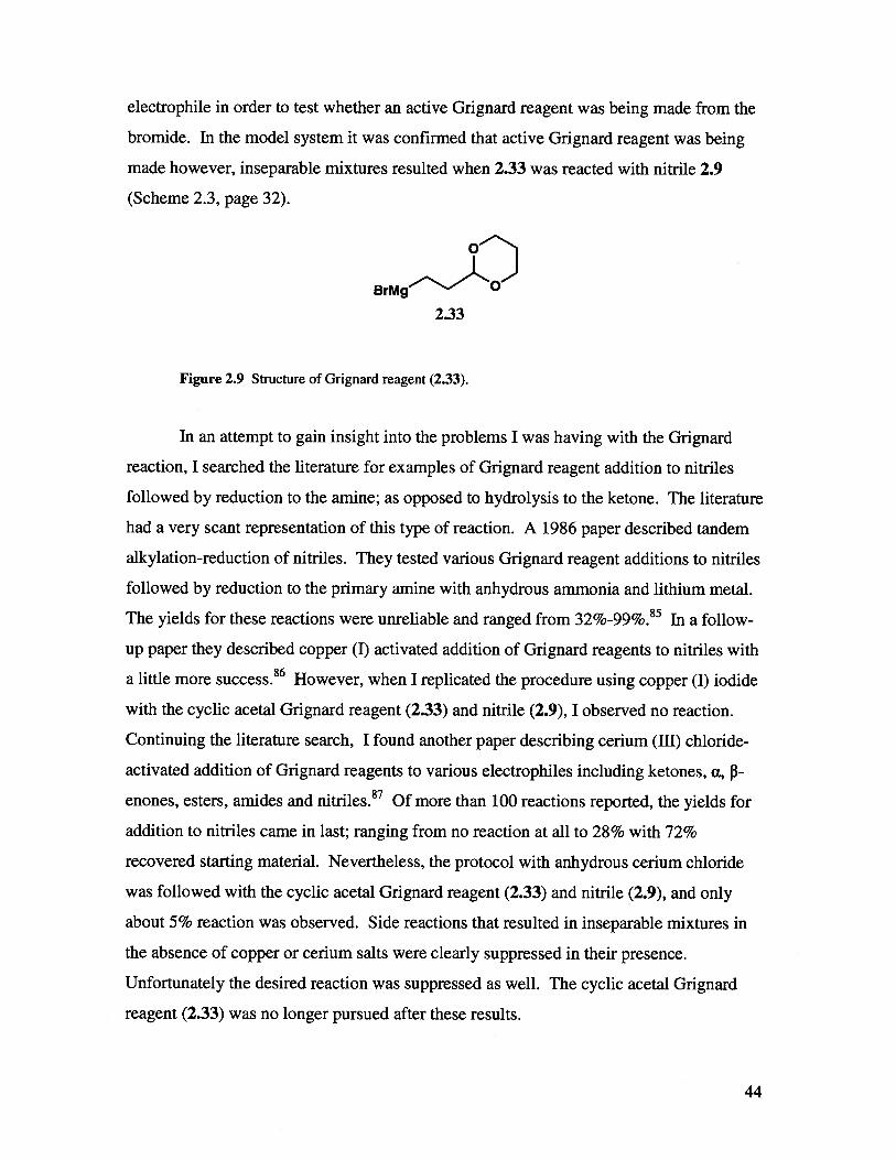
shown in Figure 2.9. After attempts to use a commercially available Grignard reagent

had failed, I tried to synthesize it in the lab. Benzaldehyde was used as a model

43

electrophile in order to test whether an active Grignard reagent was being made from the

bromide. In the model system it was confirmed that active Grignard reagent was being

made however, inseparable mixtures resulted when 2.33 was reacted with nitrile 2.9

(Scheme 2.3, page 32).

BrM 0

2.33

Figure 2.9 Structure of Grignard reagent (2.33).

In an attempt to gain insight into the problems I was having with the Grignard

reaction, I searched the literature for examples of Grignard reagent addition to nitriles

followed by reduction to the amine; as opposed to hydrolysis to the ketone. The literature

had a very scant representation of this type of reaction. A 1986 paper described tandem

alkylation-reduction of nitriles. They tested various Grignard reagent additions to nitriles

followed by reduction to the primary amine with anhydrous ammonia and lithium metal.

The yields for these reactions were unreliable and ranged from 32%99%.85 In a follow-

up paper they described copper (I) activated addition of Grignard reagents to nitriles with

a little more success.86 However, when I replicated the procedure using copper (I) iodide

with the cyclic acetal Grignard reagent (2.33) and nitrile (2.9), I observed no reaction.

Continuing the literature search, I found another paper describing cerium (III) chloride-

activated addition of Grignard reagents to various electrophiles including ketones, ci, 3-

enones, esters, amides and nitriles.87 Of more than 100 reactions reported, the yields for

addition to nitriles came in last; ranging from no reaction at all to 28% with 72%

recovered starting material. Nevertheless, the protocol with anhydrous cerium chloride

was followed with the cyclic acetal Grignard reagent (2.33) and nitrile (2.9), and only

about 5% reaction was observed. Side reactions that resulted in inseparable mixtures in

the absence of copper or cerium salts were clearly suppressed in their presence.

Unfortunately the desired reaction was suppressed as well. The cyclic acetal Grignard

reagent (2.33) was no longer pursued after these results.

44

The next strategy was to make a Grignard reagent with a protected alcohol (2.34)

which could be oxidized at a later stage (Scheme 2.11). The synthesis of the Grignard

precursor (2.35) was straightforward starting with 1,3-propane diol followed by mono-

protection with TBDPSC1. Next was de-oxygenative iodination with triphenyiphosphine,

imidazole and iodine. Unfortunately this route led to a dead end when the reagent simply

dimerized (2.36) upon treatment with magnesium as shown in Scheme 2.11.

TBDPSO’MgI÷ 2.34

Et20 TBDPSO>)

. TBDPSO...../ 3TBDPSO I

2.35 2.36

Scheme 2.11 Product resulting from dimerization of Grignard precursor (2.36). Active Grignard

(2.34) reacting with iodide (2.35) in SN2 fashion.

What can be taken from the literature search and the less than ideal results from

the Grignard reagent additions to nitrile (2.9), is that this is a difficult transformation and

has limited applicability. In my experience the best results were obtained when using

hydrocarbon and alkenyl Grignard reagents, which is also consistent with what has been

published about this reaction in the literature. It was apparent that attempts to introduce a

pre-formed acetal moiety into the molecule via a Grignard reaction were futile. The best

strategy seemed to require the use of a simple alkenyl Grignard reagent followed by

oxidation in order to develop the acetal linker afterwards. This lengthens the synthesis

considerably due to the required protecting group manipulation, but it still provides the

best route of those investigated towards C6-acetal containing IFG derivatives.

45

2.2 Inhibition Studies with Human GCase

After the desired compounds of IFG and derivatives thereof (Figure 2.10) had

been synthesized and characterized, inhibition studies with human GCase were

performed. I started with inhibition studies because the Michaelis-Menten parameters

have already been established for GCase with the substrate that was used, 2,4-

dinitrophenyl 3-D-glucopyranoside (2,4-dNP-Glu).88 Within the inhibition data collected

there was always a control with no inhibitor. These uninhibited data were used to

generate the Km and Vmax values, which always matched with what has already been

published for this system.

1.8 1.9 2.17

HOOH

2.23

HO

Figure 2.10 Compounds tested as inhibitors of GCase.

For all compounds except 1.9, a standard continuous UV-Vis spectrophotometric

assay was performed in which GCase buffer, GCase and inhibitor were pre-incubated at

37°C for ten minutes. The reactions were initiated by addition of the substrate 2,4-dNP-

Glu and the release of 2,4-dinitrophenolate was monitored at 400 nm. Steady state rates

were measured in the linear region of each curve as Abs/mm readings.

2.18

2.32

46

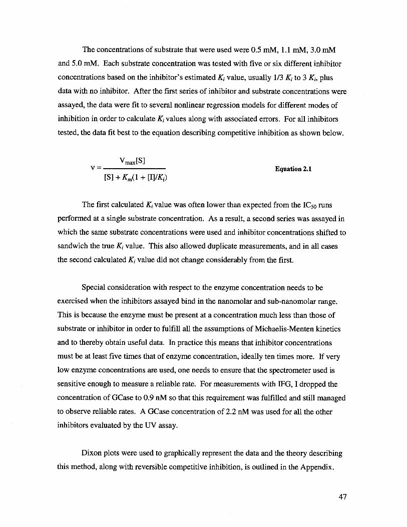
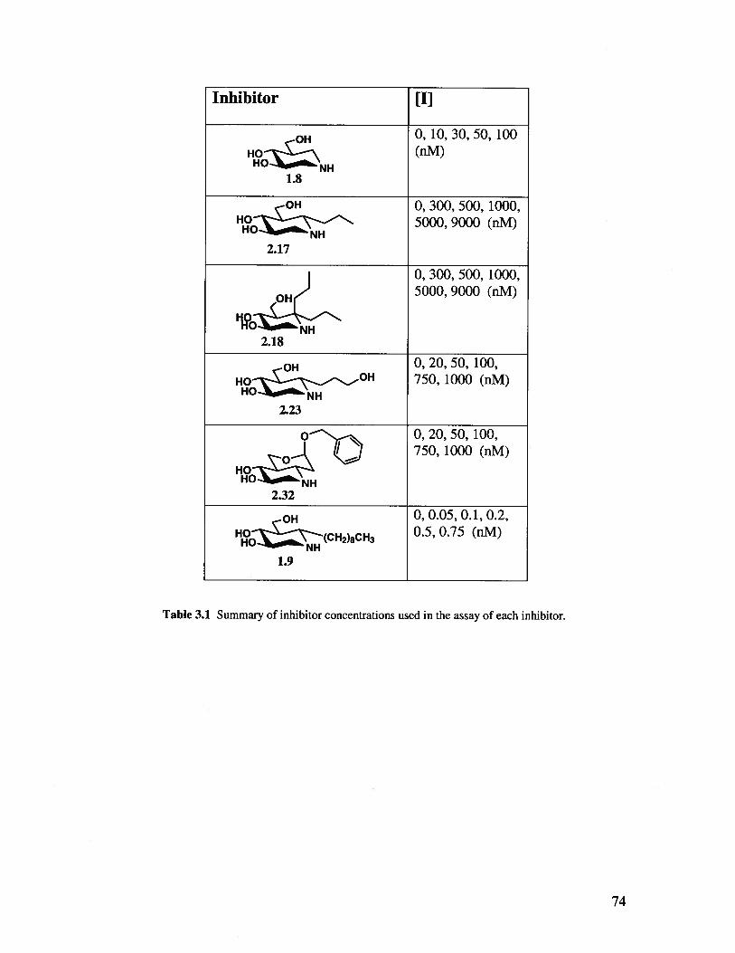
The concentrations of substrate that were used were 0.5 mM, 1.1 mM, 3.0 mM

and 5.0 mlvi. Each substrate concentration was tested with five or six different inhibitor

concentrations based on the inhibitor’s estimated K, value, usually 1/3 K1 to 3 K1, plus

data with no inhibitor. After the first series of inhibitor and substrate concentrations were

assayed, the data were fit to several nonlinear regression models for different modes of

inhibition in order to calculate K, values along with associated errors. For all inhibitors

tested, the data fit best to the equation describing competitive inhibition as shown below.

Vmax[S1V = Equation 2.1

[S] + Km(l + [I]/K1)

The first calculated K, value was often lower than expected from the 1C50 runs

performed at a single substrate concentration. As a result, a second series was assayed in

which the same substrate concentrations were used and inhibitor concentrations shifted to

sandwich the true K, value. This also allowed duplicate measurements, and in all cases

the second calculated K, value did not change considerably from the first.

Special consideration with respect to the enzyme concentration needs to be

exercised when the inhibitors assayed bind in the nanomolar and sub-nanomolar range.

This is because the enzyme must be present at a concentration much less than those of

substrate or inhibitor in order to fulfill all the assumptions of Michaelis-Menten kinetics

and to thereby obtain useful data. In practice this means that inhibitor concentrations

must be at least five times that of enzyme concentration, ideally ten times more. If very

low enzyme concentrations are used, one needs to ensure that the spectrometer used is

sensitive enough to measure a reliable rate. For measurements with lEG, I dropped the

concentration of GCase to 0.9 nM so that this requirement was fulfilled and still managed

to observe reliable rates. A GCase concentration of 2.2 nM was used for all the other

inhibitors evaluated by the UV assay.

Dixon plots were used to graphically represent the data and the theory describing

this method, along with reversible competitive inhibition, is outlined in the Appendix.

47

____

0.5 mM 2,4-dNP-Glu

1.1 mM 2,4-—a--

dNP-Glu20

_____

3.0 mlvi 2,4-A

30 ‘I

dNP-Glu

_____

5.0 mlvi 2,4-10 dNP-Glu

1/Vmax

-40 -20 0 20 40 60 80 100

[IFG] nM

Figure 2.11 Dixon plot for the inhibition of GCase by IFG (1.8).

Zhu reported the K1 value for IFG (1.8) with GCase to be 25 nM whereas I

measured it to be 23 nM ± 2, statistically the same. It was reassuring that this value

agreed with what had been published.38

80

_________________

—0--dNP-Glu

60

____

1.1 mlvi 2,4-

dNP-Glu40

___________

ii’i)I_

0.5 mM 2,4-

3.0 mlvi 2,4--*-

dNP-GIu

20

________

5.0 mM 2,4-A

dNP-Gki

___________ ___________________________

1/Vmax0

___________________________________

ililililili

-4 -2 0 2 4 6 8 10 12

[C6-n-propyl IFG] p.M

Figure 2.12 Dixon plot for the inhibition of GCase by C6-n-propyl IFG (2.17).

48

Although C6-n-propyl IFG (2.17) was a C6-n-alkyl IFG derivative of the kind

Zhu had published, this particular derivative was not synthesized or investigated. It was

desirable to see where 2.17 would fit within the trend observed by Zhu whereby five

carbons or more were needed at C6 in order to observe stronger inhibition than that

afforded by IFG (unailcylated). Compound 2.17 did fit within the trend with a measured

K1 value of 0.61 jiM ± 0.075, almost six-fold higher than the butyl derivative at 0.12

1tM.38

40

20

0

Figure 2.13 Dixon plot for the inhibition of GCase by C6,6-di-n-propyl IFG (2.18).

It was hypothesized that the tolerance of GCase for C6 axial substituents, such as

in compound 2.18, would be poor. Surprisingly, this was not the case; the dipropyl

compound (2.18) exhibited the same level of inhibition as that of 2.17 with a measured K,

value of 0.61 jiM ± 0.10. This result is particularly interesting because it forms the basis

for any future exploration of C6-axial IFG derivatives as it seems GCase has space in the

active site to accommodate a C6-axial group of at least three carbons in length.

• 0.5niM2,4-dNP-Glu

1.1 mM 2,4-dNP-Glu

A 3.0 mM 2,4-dNP-GIu

50 mM 2,4-dNP-Glu

lfVmax

-6 -4 -2 0 2 4 6 8 10

[C6,6-di-n-propyl IFGJ JIM

49

The natural substrate hydrolyzed by GCase, glucosyl ceramide (GlcCer), is quite

hydrophobic overall. However, it contains a secondary hyciroxyl group as well as an

amide bond. Amongst the inhibitors tested to date, none of the C6-alkyl IFG derivatives

have contained any hydrophilic moieties within their alkyl chain, such as the hydroxyl

group in 2.23. It was not clear how this would affect GCase binding. When this

compound was assayed as an inhibitor of GCase, the K value was measured to be 104

nM ± 19. This was lower than we had expected and perhaps suggests that a new

hydrogen bond forms between a residue in GCase and the hydroxyl group. This certainly

could account for the tighter binding of 2.23 relative to 2.17 or 2.18.

20

I 1/ -

10

_

r7 II

-1 0 1

[C6-[9-hydroxypropyl] IFG] j.tM

Figure 2.14 Dixon plot for the inhibition of GCase by C6-[9-hydroxypropylj FG (2.23).

The data for the Dixon plot associated with 2.23 showed some signs of mixed-

type inhibition because the lines do not all intersect at the l/Vmax line. However, when

the raw data were fit to the various nonlinear regression models of inhibition including

competitive, mixed type and non-competitive; the best fit was achieved with the

competitive model.

• 0.5mM2,4-dNP-Gk

-a-.dNP-Gk

A 3.OmM2,4-dNP-Glu

—*--.dNP-Glu

lNnnx

50

Previous studies performed in our group suggested that the 5’ primary hydroxyl

group (equivalent to 06 in glucose) was particularly important for inhibitory power.

When this hydroxyl group was replaced with a fluorine atom, there was a substantial

decrease in the inhibitory ability of the compound compared to the parent compound,

presumably due to the deletion of an important hydrogen bond. In compound 2.32, the

intramolecular acetal involves the 5’ hydroxyl group, reducing the opportunities for

hydrogen bonding. However, since the inclusion of a benzyl group might improve

affinity, it was not clear what the overall effect would be. In fact, the K value was

measured to be 160 nM ±6, still quite a good inhibitor.

40

____

I

___

20

__

0

I

-1 0 1

[C6-benzyl acetal IFG] j.tM

Figure 2.15 Dixon plot for the inhibition of GCase by C6-benzyl acetal IFG (2.32).

Due to the limited amount of 2.32 that remained, inhibition studies could not be

performed on the cleaved version of the acetal, 2.27 (Figure 2.7). As it happens, it is

unlikely that this version would cleave under physiological conditions anyway. So this

was not deemed to be a crucial measurement.

51

Measurement of the K, value of C6-n-nonyl IFG (1.9) was rendered much more

challenging by its anticipated sub nanomolar K1 value. As mentioned previously, the

inhibitor concentration must be at least five times that of the enzyme concentration in

order to obtain reliable data. In attempting to satisfy this requirement when assaying C6-

n-nonyl IFG (1.9) with the continuous UV-Vis assay, very low enzyme concentrations

had to be used and the rates observed were not reliable when substrate concentrations

were low and inhibitor concentrations high. This indicated that the level of sensitivity of

the UV-Vis spectrophotometer had been reached and that this assay could not be used to

measure the K, value of 1.9.

A more sensitive instrument, a fluorimeter, was used in order to investigate the

inhibitory properties of 1.9. The idea behind a fluorescent assay is the same as with the

UV assay with respect to rate measurement at various substrate and inhibitor

concentrations, however, the practicalities are different. The fluorescent substrate, 4-

methylumbelliferryl 3-D-glucopyranoside (4-MU-Glu) was used and the rate of release of

4-methylumbelliferrone was measured; much in the same way as the UV-Vis assay

measures the release of 2,4-dinitrophenolate. Since GCase operates in the lysosome and

has a pH optimum of around 5.5, this is the pH at which the inhibition is measured. The

cleaved substrate however does not emit sufficient fluorescence at this pH and therefore,

the pH must be raised above pH 10 in order to fully observe the fluorescence of the

cleaved moiety. This requires the assay to be stopped rather than continuous.

Buffered solutions containing the substrate were pre-incubated at 37°C in

Eppendorf vials in the presence or absence of inhibitor (1.9). The reaction was initiated

by addition of GCase to a total concentration of 5 pM, then at fixed time intervals of 3, 6

and 9 minutes, 100 iL aliquots were removed and diluted into a cuvette containing 500

iL of glycine buffer at pH 10.8. This both stopped the enzyme reaction and ionized the

4-methylumbelliferrone product, increasing its fluorescence to an observable intensity.

Rates were calculated by linear regression of the fluorescence intensity measured at each

time point with each fluorescence value being an average of 15 individual readings. The

data were fit to the inhibition models in the same manner as with the other compounds,

52

and the K, value of 1.9 was measured to be 0.2 nM ± 0.01. This is a remarkably potent

inhibitor and the strongest towards GCase measured to date. It also clearly exhibits

competitive inhibition, laying to rest the claims made by Zhu that this is a mixed-type

inhibitor.38

0.4

Putting all the K, values that I measured into context with what has been

published in the literature suggests that C6-alkyl IFG derivatives are among the most

potent inhibitors of GCase. Many of the compounds assayed thus far as inhibitors of

GCase have had their inhibitory power evaluated by IC50 values, which are not directly

comparable to K1 values, but can offer a rough comparison. Figure 2.17 shows several

different iminosugars as well as nitrogen-containing heterocycles and their respective

IC50 values towards GCase. Most of these previously published inhibitors are in the mid

to low micromolar range whereas all the compounds I tested are in the sub micromolar to

sub nanomolar range.

I0.2

0

-0.2

_____

0.5 mM4-MU- Glu

1.1mM4-MU-Glu

____

3.0mM*

4-MU-Gin

l/Vmax

-0.4 -0.2 0 0.2 0.4 0.6 0.8

[C6-n-nonyl IFG] (nM)

Figure 2.16 Dixon plot for the inhibition of GCase by C6-n-nonyl IFG (1.9).

1

53

N-butyl DNJ

IC50 = 270 jiM

HON

x- I -C-nonyl DNJ

IC50 = 0.27 jiM

OHN-adamantyl amide IFG

HO H 1C50=18j.tM-i-to N

OH

N-octyl-3-valienamine

IC50 = 0.5 jiM

2

O%NH

Thio-quinazoline

1C50=7.8j.tM

Figure 2.17 Diagram of several inhibitors of GCase and their IC50 values. Sulfonamide

value obtained from Zheng et. al. thio-quinazoline value obtained from Tropak et. at. ,

and all other values obtained from Butters.72

2.3 Conclusions

In summary, I was successful in synthesizing five IFG derivatives in

addition to IFG. Four of these derivatives were novel compounds (2.17, 2.18, 2.23 and

2.32). All the synthesized compounds were evaluated for their inhibitory ability towards

OH

N-butyl IFGIC50 =44jiM

OHHO H

NNTh(

0

0Sulfonamide

IC50 = 6.5 jiM

54

human GCase by measuring their K, values, which are summarized in Table 2.1 below.

Some compounds have been sent, with the remainder to be sent shortly, to our

collaborators Dr. Don Mahuran and Dr. Mike Tropak (Hospital for Sick Children,

Toronto) in order to test their ability to behave as PCs in Gaucher cell lines.

Inhibitor K,

OH 23nM±2

1.8

OH 6lOnM±75

2.17

6lOnM+ 100

OH -

9?2.18

OH lO4nM±19

2.23

0N_— l6OnM±6

HOHO NH2.32

0.2nM±0.01OH

1.9

Table 2.1 Summary of inhibitors synthesized and measured K1 values towards GCase.

55

3 Materials and Methods

3.1 Synthesis

3.1.1 General materials and methods

All reagents were purchased from commercial suppliers (Sigma, Aldrich, Fluka,

Alfa Aesar and Reike Metals) and were used without further purification, unless

otherwise stated. Solvents used were either reagent, certified or spectral grade.

Anhydrous/dry solvents were prepared as follows: CH2C12and pyridine were distilled

over CaH2;THF and diethyl ether were distilled over sodium and benzophenone;

methanol was distilled over magnesium and iodine; DMF was dried over 4 A molecular

sieves for 2 days prior to use. Deionized water, purified with a Millipore DirectQTM 5

Ultrapure Water system, was used for all aqueous solutions. Melting points were

determined using a Laboratory Devices Mel-Temp II melting point apparatus and are

uncorrected.

Thin layer chromatography (TLC) was used to follow all reactions. TLC

separations were performed using Merck Kieselgel silica gel 60 F254 aluminum-backed

analytical plates. Compounds were detected using ultra violet light (where applicable)

and/or stained with 10 % ammonium molybdate in 2 M H2S04(polyhydroxylated

compounds), silica gel impregnated with iodine (general use), or 0.3 % ninhydrin and 3%

acetic acid in ethanol (amines). All flash column chromatography was performed under

elevated pressure on Sili-Cycle silica gel, 230-400 mesh. All reverse phase (RP) column

chromatography was performed under elevated pressure using 2 g Waters Sep-Pak C-18

RP cartridges.

All 1H nuclear magnetic resonance (NMR) spectra were either recorded on a

Bruker AV-400 (400 MHz) or a Bruker WH-400 (400 MHz) spectrometer and chemical

shifts are given in parts per million (ppm) as referenced from tetramethylsilane (TMS).

Samples were referenced internally to CD3OD at 3.31 ppm, CDC13 at 7.27 ppm, D20 at

56

4.78 ppm and acetone-d6at 2.05 ppm. Abbreviations describing the multiplicity of

signals are: s-singlet, bs-broad singlet, d-doublet, t-triplet and m-multiplet. All 13C NIVIR

spectra are proton decoupled and were recorded on either a Bruker AV-400 (100 MHz) or

a Bruker WH-400 (100 MHz) spectrometer. Samples were referenced internally to

CD3OD at 49.15 ppm, CDC13 at 77.16 ppm, acetone-d at 29.8 ppm, and when D20 was

used, CD3OD was added as an external reference. Low resolution mass spectra (LRMS)

were acquired on an electrospray ionization (ESI) Waters liquid chromatography — mass

spectrometer (LC-MS) and high resolution mass spectra (HRMS) were acquired on an

ESI Micromass LCT spectrometer by the mass spectrometry laboratory at the University

of British Columbia. In cases where the desired compound has already been reported, all

analytical data were identical to that already reported and referenced as such.

3.1.2 Generous Gifts

Dr. Hong-Ming Chen in the Withers laboratory synthesized 2,4-dinitrophenyl 13-D-glucopyranoside.

3.1.3 (3R, 4R, 5R)-5-(Hydroxymethyl)piperidine-3,4-diol [Isofagomine. HC1 salt]

(1.8)

Benzyl x-L-xylopyranoside (2.2)38

1OH

OBn

Boron trifluoride etherate (1.5 mL, 11.8 mmol) was added to a suspension of L

xylose (2.1) (17.9 g, 119 mmol) in benzyl alcohol (90 mL). The reaction mixture was

stirred at 105 °C for 3 hours and at room temperature for 16 hours. All contents of the

reaction flask were poured into an Erlenmeyer flask of cold diethyl ether (1.5 L) where a

white precipitate formed immediately. Crystallization at 0 °C took 72 hours to complete.

Crystals were harvested by suction filtration and re-crystallized from hot ethanol to yield

57

2.2 as white prisms (11.3 g, 47 mmol, 39%). 1H NMR (acetone — d6) 6 7.28-7.43 (m, 5

H, (Ph)), 4.83 (d, Ji,2 = 3.6 Hz, 1 H, H(1)), 4.75 (d, JphdH2=12.1 Hz, 1 H, (PhCH2)), 4.50

(d, JphdH2= 12.1 Hz, 1 H, (PhCH2)), 4.05 (dd, J5ax,5eq = 12.6 Hz,J54=3.4 Hz, 1 H,

H(5eq)), 3.48-3.66 (m, 3 H, H(3), H(5ax), H(4)), 3.39 (m, 1 H, H(2)). ‘3C NMR

(acetone — d6) 6 128.8, 129.0, 129.6, 99.9 (C(l)), 75.9, 74.1, 71.8, 70.2, 63.7. ESI MS

m/z 263.2 [M + NaT. Calculated forC12H16NaO5263.1.

Benzyi 2,3-O-isopropylidene-u-L-xylopyranoside (2.3)38

OH

00

OBn

A solution of p-toluenesulfonic acid monohydrate (210 mg, 1.22 mmol) and THF

(3 mL) was added by syringe to a solution of the benzyl xyloside (2.2) (10.5 g, 43.7

mmol) and 2-methoxypropene (10.5 mL, 110 mmol) in anhydrous THF (100 mL) at 0°C.

The reaction mixture was quenched with triethylamine (0.7 mL) after 1.5 hours, then

diluted with EtOAc (280 mL) and washed with ice water (2 x 200 mL) and saturated

aqueous NaC1 (200 mL). The organic portion was dried over anhydrous Mg504,filtered

and concentrated in vacuo. The residue was purified by flash column chromatography on

silica gel (3.5:1 hexanes : EtOAc with 0.1% Et3N) to yield 2.3 as a clear syrup (5.99 g,

21.4 mmol, 49%). 1H NMR (CD3OD) 67.27-7.39 (m, 5 H, (Ph)), 5.16 (d,J12= 3.0 Hz, 1

H, H(1)), 4.78 (d, JPhCH2 = 12.0 Hz, 1 H, (PhCH2)), 4.60 (d, JPhCH2 = 12.0 Hz, 1 H,

(PhCH2)), 3.94 (dd, J3,2 = J3,4 = 9.5 Hz, 1 H, H(3)), 3.86 (ddd, J4,3 =J4,5ax = 9.5 Hz, =

5.2 Hz, 1 H, H(4)), 3.58 (dd,J5=11.2 Hz,J5 = 5.2 Hz, 1 H, H(5eq)), 3.36 (dd, J2,3

= 9.5 Hz, J,j = 3.0 Hz, 1 H, H(2)), 3.31 (masked by MeOD, H(Sax)), 1.33 (s, 3 H,

(CH3)), 1.32 (s, 3 H, (CH3)). ‘3C NMR (CD3OD) 6 129.5, 128.9, 111.6, 97.6 (C(1)),

81.7, 78.4 (C(3)), 77.4 (C(2)), 71.1 (C(4)), 70.7, 64.4 (C(5)), 27.3, 26.9. ESI MS m/z

303.3 [M + Na1. Calculated forC15H20NaO5303.1.

58

Benzyl 4-O-acetyl-2,3-O-isopropylidene-a-L-xylopyranoside (2.8)

OAc

00

OBn

Acetic anhydride (3 mL) was added by syringe to a solution of the alcohol (2.3)

(40 mg, 0.14 mmol) and pyridine (3 mL) at 0 °C. The reaction mixture was quenched

with cold water (8 mL) after 6 hours, extracted with CH2C12(2 x 20 mL) and washed with

saturated aqueous NaHCO3(2 x 15 mL), water (20 mL) and saturated aqueous NaC1 (20

mL). The organic portion was dried over anhydrous MgSO4,filtered and concentrated in

vacuo to yield 2.8 as a clear syrup. ‘H NIVIR (CDC13)6 7.37-7.38 (m, 5 H, (Ph)), 5.24 (d,

J1,2:= 3.1 Hz, 1 H, H(1)), 5.06 (ddd,J43=J4,5ax= 9.6 Hz, J4,5eq 5.5 Hz, 1 H, H(4)), 4.80

(d, JPhCH2 12.1 Hz, 1 H, (PhCH2)), 4.65 (d, JPhCH2 12.1 Hz, 1 H, (PhCH2)), 4.19 (t, J32

= J34 = 9.6 Hz, 1 H, H(3)), 3.92 (dd, J5eq,5ax 10.8 Hz, J5eq4 = 5.5 Hz, 1 H, H(Seq)), 3.56

(dd, J2,3 = 9.6 Hz, J2,1 = 3.1 Hz, 1 H, 11(2)), 3.34 (dd,J5ax,5= 10.8 Hz,J5ax,4= 9.6 Hz, 1

H, H(Sax)), 2.09 (s, 3 H), 1.50 (s, 3 H, (CH3)), 1.47 (s, 3 H, (CH3)).

Benzyl 4-cyano-4-deoxy-2,3-O-isopropy1idene--D-arabinopyranoside (2.9)38

NUI

OBn(

Tf20 (1.3 mL, 7.7 mmol) was added dropwise by syringe to a solution of the

alcohol (2.3) (1.44 g, 5.14 mmol) and dry pyridine (2 mL) in anhydrous CH2C12(20 mL)

at -78 °C under an inert atmosphere. The reaction mixture was warmed to 0 °C after

addition was complete and stirred for an additional 2 hours. Upon warming, a dark red

color persisted. The reaction mixture was then diluted with EtOAc (140 mL), washed

with ice water (2 x 120 mL), saturated aqueous NaC1 (1 x 120 mL) and re-extracted with

EtOAc (100 mL). The organic layer was dried over anhydrous MgSO4,filtered and

concentrated in vacuo to yield a dark red syrup that was used immediately without further

59

purification. The mixture of the crude triflate, KCN (3.3 g, 50.8 mmol), 18-crown-6 (1.5

g) and 3 A MS (3 g) in dry DMF (110 mL) was stirred at room temperature for 16 hours.

The reaction mixture was diluted with EtOAc (160 mL), washed with water (2 x 160

mL), saturated aqueous NaCJ (1 x 160 mL) and re-extracted with EtOAc (100 mL). The

organic portions were dried over anhydrous MgSO4,filtered and concentrated in vacuo.

The resulting residue was purified by flash column chromatography on silica gel (CH2C12

with 0.1 % Et3N) to yield 2.9 as a pale yellow syrup (1.18 g, 4.08 mmol, 80%). ‘H NMR

(CDC13)ö 7.3 1-7.37 (m, 5 H, (Ph)), 5.37 (d, J,,2= 2.7 Hz, 1 H, H(1)), 4.78 (d, JPhCH2

12.0 Hz, 1 H, (PhCH2)), 4.68 (d, JPhCH2 12.0 Hz, 1 H, (PhCH9)), 4.13 (dd,J3,2= 9.6 Hz,

J3,4= 4.7 Hz, 1 H, H(3)), 3.89-3.96 (m, 2 H, H(2), H(5a)), 3.79 (dd,J5b,5a 12.1 Hz, J5b,4

= 2.6 Hz, 1 H, H(5b)), 3.28-3.35 (m, 1 H, H(4)), 1.51 (s, 3 H, (CH3)), 1.50 (s, 3 H,

(CH3)). ‘3C NMR (CDC13)ö 136.8, 128.3, 127.8, 127.5, 116.9 (C(CN)), 110.8, 97.5

(C(1)), 74.4 (C(2)), 70.0, 69.3 (C(3)), 59.1 (C(S)), 34.0 (C(4)), 26.5, 26.4. ESI MS m/z

312.2 [M + NaTt. Calculated forC,6H19NNaO4312.1.

(3R, 4R, 5R)-N-Benzyloxycarbonyl-5-(hydroxymethyl)piperidine-3,4-dioi (2.15)

HO-\HO.L%I.III..NCbZ

21

Pd(OH)2/C(20% , 60 mg) was added to a solution of the nitrile (2.9) (150 mg,

0.52 mmol) and glacial acetic acid (8 pL) in dry methanol (6 mL) and the mixture was

hydrogenated in a high pressure reactor at 50 psi for 72 hours. The catalyst was removed

by suction filtration through Celite then the filter cake was washed with methanol (30

mL) and acetone (30 mL). The filtrates were concentrated in vacuo, dissolved in 1 M

HCJ (20 mL) and stirred for 12 hours. The solution was concentrated in vacuo and

partially purified by ion exchange chromatography (Amberlite CG-50 type I, NH4form)

using aqueous 0.35 M NH4OH as an eluent after the water wash. The fractions

containing the desired product were concentrated in vacuo to yield impure isofagomine

(1.8) as a pale yellow crystalline solid (68 mg, 0.46 mmol, 89%). Benzyl chioroformate

(0.12 mL, 0.84 mmol) was then added to a solution of isofagomine (1.8) (90 mg, 0.61

60

mmol) and NaHCO3(156 mg, 1.86 mmol) inH2OIMeOH/THF (2:1:1, 10 mL) and the

mixture was stirred at room temperature for 20 hours. The reaction was quenched by

adding 1 M HC1 (1 mL), concentrated in vacuo, co-evaporating with toluene. The

residue was then purified by flash column chromatography on silica gel (petroleum

ether:EtOAc 1:1 then MeOH:CHC131:9) to yield (2.15) as a clear oil (59 mg, 0.21 mmol,

35%). 1H NMR (MeOD)6 7.28-7.39 (m, 5 H, (Ph)), 5.12 (s, 2 H, (COOCH2Ph)), 4.13-

4.31 (m, 2 H, H(6a), H(2a)), 3.82 (dd, J = 10.9 Hz, J 3.5 Hz, 1 H, H(5’a)), 3.46-3.64

(m, 1 H, H(5’b)), 3.32-3.38 (m, 1 H, H(3)), 3.25 (dd, J = 11.0 Hz, J = 9.0 Hz, 1 H, H(4)),

2.50-2.79 (m, 2 H, H(6b), H(2b)), 1.55-1.67 (m, 1 H, H(5)). 13C NMR (MeOD) 157.2,

138.4, 129.9, 129.5, 129.2, 75.9, 72.9, 68.8, 62.3, 49.8, 46.9, 46.2, 46.0. HRMS (ESI)

m/z 304.1167 [M + Na]. Calculated forC14H19NNaO5304.1161.

(3R, 4R, 5R)-5-(Hydroxymethyl)piperidine-3,4-diol [Isofagomine.HCI salt] (1.8)

4 6

HOHO NH2

1 •HCI

PdJC (10%, 10 mg) was added to a solution of IFG-Cbz (2.15) (28 mg, 0.10

mmol) and glacial acetic acid (8 iL) in dry methanol (6 mL) and the mixture was

hydrogenated at atmospheric pressure for 10 hours. The catalyst was removed by suction

filtration through Celite then the filter cake was washed with methanol (30 mL) and water

(30 mL). The filtrates were concentrated in vacuo, dissolved in 1 M HC1 (5 mL) and

stirred for 12 hours. The solution was concentrated in vacuo and then lyophilized from

water (2 mL) to yield 1.8 as a pale yellow solid (13 mg, 0.46 mmol, 89%). Analytical

data matches that reported in Zhu et. al.38 1H NMR (D20) 8 3.85 (dd, J5’a, 5’b = 11.7 Hz,

= 3.5 Hz, 1 H, H(5’a)), 3.73-3.82 (m, 2 H, H(5’b), H(3)), 3.50-3.59 (m, 3 H,

H(2eq), H(4), H(6eq)), 2.85-3.04 (m, 2 H, H(6ax), H(2ax)), 1.92-2.04 (m, 1 H, H(5)).l3 NMR (MeOD) 672.3 (C(4)), 69.7 (C(3)), 60.1 (C(5’)), 47.8, 46.0 (C(2), C(6)), 42.3

(C(5)). HRMS (ESI) m/z 148.0972 [M + H]. Calculated forC6H14N03148.0974.

61

3.1.4 (3R, 4R, 5R, 6S)-6-n-Nonyl-5-(hydroxymethyl)piperidine-3,4-diol [C6-n-Nonyl

IFG•HC1 salt] (1.9)

Benzyl 4-[(S)-1 ‘-aminodecyl]-4-deoxy-2,3-O-isopropylidene-p-D-arabinopyranoside

(2.16)38

OBn

n-C9H,9MgBr (3.4 mL of 1.0 M solution in diethyl ether) was added dropwise by

syringe to a solution of the nitrile (2.9) (260 mg, 0.9 mmol) in dry diethyl ether (35 mL)

at -78°C under an inert atmosphere and then slowly warmed to room temperature and

stirred for 4 hours. The reaction mixture was heated at 35°C for 1.5 hours then cooled to

room temperature before NaBH4 (200 mg, 5.3 mmol) was added in one portion. The

reaction mixture was then cooled to 0°C and dry methanol (13 mL) was added by syringe

for 5 minutes, then allowed to warm to room temperature and stirred overnight. Water

(20 mL) and diethyl ether (20 mL) were added to the reaction mixture and the solids

removed by suction filtration then washed with diethyl ether (15 mL). The filtrate was

washed with water (2 x 20 mL), saturated aqueous NaCl (20 mL) and re-extracted from

the aqueous portion with diethyl ether (20 mL). The organic portions were dried over

anhydrous MgSO4,filtered and concentrated in vacuo. The resulting residue was purified

by flash column chromatography on silica gel (20:1 CH2C12:MeOH with 0.1% Et3N) to

yield 2.16 as a pale yellow syrup (163 mg, 0.39 mmol, 43%). ‘H NMR (CDC13)ö 7.19-

7.29 (m, 5 H, (Ph)), 5.17 (d,J1,2= 2.8 Hz, 1 H, H(1)), 4.68 (d, JphdH2= 12.2 Hz, 1 H,

(PhCH2)), 4.54 (d, JPhCm = 12.2 Hz, 1 H, (PhCH2)), 4.25 (dd, J3,2 = 9.9 Hz, J3,4 = 4.6 Hz,

1 H, H(3)), 3.79 (dd, J23 = 9.9 Hz, J21 = 2.8 Hz, 1 H, H(2)), 3.57-3.67 (m, 2 H, H(5a),

H(5b)), 3.13-3.22 (m, 1 H, H(1’)), 2.25-2.45 (bs, 2 H, (NH2)), 1.95-2.05 (m, 1 H, H(4)),

1.54-1.57 (m, 1 H, H(2’a)), 1.39 (s, 6 H, (2 x CH3)), 1.10-1.27 (m, 15 H, H(2’b-9’)), 0.81

(t, Jio’,9’a= J,O’,9’b= 6.3 Hz, 3 H, H(10’)). 13C NMR (CDC13)6 137.2, 128.0, 127.3, 127.2,

62

108.8, 97.2 (C(1)), 74.0 (C(3)), 72.4 (C(2)), 69.2, 59.5 (C(5)), 47.9 (C(1’)), 46.7 (C(4)),

34.7, 31.6, 29.5, 29.3, 29.2, 29.0, 26.7, 26.0, 25.0, 22.3, 13.8 (C(10’)). ESI MS m/z 420.3

[M + H]. Calculated forC25H42N04420.3.

(3R, 4R, 5R, 6S)-6-n-Nonyl-5-(hydroxymethyl)piperidine-3,4-diol [C6-n -Nonyl IFG•

HC1 salt] (1.9•HCI)38

3 1 •HCI

Pd(OH)2/C(20%, 80 mg) was added to a solution of amine (2.16) (160 mg, 0.38

mmol) and glacial acetic acid (8 pL) in dry methanol (20 mL) and the mixture was

hydrogenated in a high pressure reactor at 50 psi for 20 hours. The catalyst was removed

by suction filtration through Celite and the filter cake washed with methanol (30 mL).

The filtrate was concentrated in vacuo, dissolved in 1 M HC1 (25 mL), and stirred at

room temperature for 12 hours. The solution was then concentrated in vacuo and purified

by colunm chromatography using C-18 RP silica gel, eluted with 30 % methanol in water

for the HC1 salt product and 60 % methanol in water for the neutral product. Each set of

fractions was then lyophilized from water (15 mL) to yield a white foam of 1.9•HC1 (40

mg, 0.15 mmol) and 1.9 (35 mg, 0.13 mmol) with a combined yield of 72 %. 1H NMR

(CD3OD) 4.02 (dd,J5’a,5’b 11.4 Hz,J5’a,5 2.4 Hz, 1 H, H(5’a)), 3.64-3.70 (m, 2 H,

H(5’b), H(3)), 3.54 (t, J4,3 J4,5 = 9.6 Hz, 1 H, H(4)), 3.35 (dd, J2eq,2ax = 12.2 Hz, J2eq,3 =

4.9 Hz, 1 H, H(2eq)), 3.25 (ddd, J = 11.0 Hz, J = 7.6 Hz, J = 3.4 Hz, 1 H, H(6)), 2.79 (t,

J2ax,2eq J2ax,3 12.2 Hz, 1 H, H(2ax)), 1.88-1.98 (m, 1 H, H(7a)), 1.59-1.70 (m, 1 H,

H(7b)), 1.20-1.59 (m, 15 H, H(5), H(8aIb), H(9-14)), 0.90 (t,J15,14a= J15,14b 6.9 Hz, 3 H,

H(15)). ‘3C NMR (CD3OD) ö 72.2 (C(4)), 70.3 (C(3)), 58.2 (C(6)), 57.5 (C(2)), 48.1

(C(5’)), 47.1 (C(5)), 33.2, 31.4, 30.8, 30.7, 30.6, 30.5, 25.8, 23.9, 14.6 (C(15)). HRMS

(ESI) in/z 274.2389 [M + H]. Calculated forC15H32N03274.2382.

63

(3R, 4R, 5S, 6S)-6-n-Nonyl-5-(hydroxymethyl)piperidine-3,4-diol [C6-n-Nonyl LEG]

(1.9)

HO%

‘H NMR (CD3OD) ö 3.93 (dd,J5’a,5=2.7 Hz,J5’a,5’b 11.2 Hz, 1H, H(5’a)), 3.69

(dd,.15’b,5’a= 11.2 Hz, J5’b,5= 3.3 Hz 1H, H(5’b)), 3.36-3.46 (m, 2 H, H(4), H(3)), 3.09

(dd, J2eq,2ax = 11.3 Hz, J2eq, = 4.0 Hz 1 H, H(2eq)), 2.56-2.64 (m, 1 H, H(6)), 2.40 (t,

J2ax,2eq=J2ax,3= 11.3 Hz, 1 H, H(2ax)), 1.69-1.8 (m, 1 H, H(7)), 1.10-1.52 (m, 16 H, H(5),

H(7), H(814)), 0.90 (t,J15,14a= J,5,14b= 6.8 Hz, 3 H, H(15)). ‘3C NMR (CD3OD) ö 75.2

(C(4)), 74.0 (C(3)), 59.4 (C(5’)), 57.1 (C(6)), 51.5 (C(2)), 50.3 (C(5)), 34.1, 33.4, 31.5,

31.0. 30.8, 30.6, 26.7, 24.1, 14.8 (C(15)).

3.1.5 (3R, 4R, 5R, 6S)-6-n-Propyl-5-(hydroxymethyl)piperidine-3,4-diol [C6-n-

Propyl IFG• HCI salt] (2.17)

Benzyl 44(S)-i’ -amino-3’ -butenyl]-4-deoxy-2,3-O-isopropy1idene--D-

arabinopyranoside (2.19)H2N

0

00

OBn

Allyl magnesium chloride (0.63 mL of 2.0 M solution in THF) was added

dropwise by syringe to a solution of the nitrile (2.9) (221 mg, 0.76 mmol) in dry diethyl

ether (15 mL) at 0°C under an inert atmosphere and then slowly warmed to room

temperature and stirred for 3 hours. The reaction mixture was cooled to 0°C, NaBH4

(140 mg, 3.6 mmol) was added in one portion and then dry methanol (4 mL) was added

by syringe over 5 minutes. The reaction mixture was warmed to room temperature after

the addition was complete and allowed to stir overnight. Water (8 mL) and diethyl ether

(8 mL) were added to the reaction mixture, and then the solids were removed by suction

64

filtration and washed with diethyl ether (10 mL). The filtrate was washed with saturated

aqueous NaHCO3(15 mL) then extracted with diethyl ether (2 x 20 mL) and EtOAc (20

mL). The organic portions were dried over anhydrous MgSO4,filtered and concentrated

in vacuo. The residue was purified by flash column chromatography on silica gel

(gradient of 5% to 8% to 10% EtOAc in CH2C12with constant 0.1% Et3N) to yield 2.19

as a pale yellow oil (193 mg, 0.58 mmol, 72 %). 1H NMR (CDC13)ö 7.28-7.39 (m, 5 H,

(Ph)), 5.78-5.91 (m, 1 H, H(3’)), 5.26 (d,J12= 3.1 Hz, I H, 11(1)), 5.07-5.20 (m, 2 H,

H(4’alb)), 4.76 (d, JphdH2= 12.1 Hz, 1 H, (PhCH2)), 4.62 (d, JPhCH2 12.1 Hz, 1 H,

H(PhCH2)),4.33 (dd,J3,= 9.9 Hz,J34= 4.8 Hz,1 H, H(3)), 3.88 (d,J2,3= 9.9 Hz, J2j =

3.1 Hz, 1 H, H(2)), 3.76 (dd,J5a,5b 12.4 Hz,J5a,4 1.0 Hz, 1 H, H(5a)), 3.69 (dd,J5b,5a=

12.4 Hz, J5b,4= 3.0 Hz, 1 H, H(5b)), 3.35 (ddd, Jl’ ‘= J1’,2’b= 9.1 Hz, J1’,4= 3.0 Hz, 1 H,

H(1’)), 2.44-2.53 (m, 1 H, H(2’a)), 1.84-2.16 (m, 4 H, H(2’b), H(4), (NH2)), 1.47 (s, 6

H, (2 x CH3)). 13C NMR (CDC13)ö 137.4, 134.7 (C3’)), 128.3, 127.6, 127.4, 118.0

(C(4’)), 109.0, 97.5 (C(1)), 74.1 (C(3)), 72.7 (C(2)), 69.4 (C(PhCH2)),59.7 (C(5)), 47.4

(C(l’)), 46.5 (C(4)), 39.5 (C(2’)), 26.8 (C(CH3),26.3 (C(CH3). HRMS (ESI) mlz

334.2014 [M + H]. Calculated forC19H28N04334.2018.

Benzyl 4-[[(S)-1 ‘-N-Benzyloxycarbonyl]-3’ -butenyl]-4-deoxy-2,3-O-isopropylidene-

-D-arabinopyranoside (2.20)

Benzyl chloroformate (121 L, 0.86 mrnol) was added to a solution of the amino

olefin (2.19) (150 mg, 0.45 mmol) in pyridine (2.5 mL), CH2C12(2.5 mL) and DMAP (6

mg, 45 imol) at room temperature and allowed to stir for 60 hours. The reaction mixture

was concentrated in vacuo, dissolved in CH2C12 (20 mL), washed with water (20 mL),

and re-extracted with CH2C12(2 x 20 mL). The organic portions were combined and

washed with saturated aqueous NaCT (20 mL), dried over anhydrous MgSO4and

concentrated in vacuo. The residue was purified by flash column chromatography on

65

silica gel (20:1 CH2C12:EtOAc with 0.1% Et3N) to yield 2.20 as a white crystalline solid

(m.p. 115-117°C) (134 mg, 0.28 mmol, 64%). 1H NMR (CDC13) 7.27-7.40 (m, 5 H,

(Ph)), 5.72-5.87 (m, 1 H, H(3’)), 5.45-5.59 (bs, 1 H, (NH)), 5.26 (d, J,,2= 2.9 Hz, 1 H,

H(1)), 5.03-5.17 (m, 4 H, H(4’a), H(4’b), (COOCH2Ph)), 4.76 (d, JPhCH2 12.1 Hz, 1 H,

(PhCH,)), 4.63 (d, JphdH2= 12.1 Hz, 1 H, (PhCH2)), 4.27 (dd,J3,2= 10.0 Hz,J3,4= 4.3 Hz

1 H, H(3)), 4.11-4.23 (m, 1 H, H(1’)), 3.88 (dd, J23 = 10.0 Hz, J21 = 2.9 Hz, 1 H, H(2)),

3.71 (dd,J5a,5b = 12.3 Hz,J5a,4 = 2.7 Hz, 1 H, H(5a)), 3.63 (d,J5b,5a= 12.3 Hz, 1 H,

H(5b)), 2.61-2.70 (m, 1 H, H(2’a)), 2.19-2.36 (m, 2 H, H(4), H(2’b)), 1.42 (s, 3 H,

(CH3)), 1.32 (s, 3 H, (CH3)). 13C NMR (CDC13) 133.5 (C(3’)), 128.6, 128.5, 128.2,

128.1, 127.8, 127.6, 118.6 (C(4’)), 114.6, 109.7, 97.9 (C(1)), 74.1 (C(3)), 72.6 C(2)),

69.8, 66.6, 60.4 (C(S)), 47.8 (Cl’)), 42.0 (C(4)), 36.1 (C(2’)), 26.7 (C(CH3)), 26.5

(C(CH3)). HRMS (ESI) m/z 490.2205 [M + Na]. Calculated forC27H33NNaO6

490.2206

(3R, 4R, 5R, 6S)-6-n-Propyl-5-(hydroxymethyl)piperidine-3,4-diol [C6-n-Propyl

IFG•HC1 salt] (2.17)

HO

HCI

Pd/C (10%, 20 mg) was added to a solution of the terminal olefin (2.20) (50 mg,

0.15 mmol) and glacial acetic acid (8 jiL) in dry methanol (3 mL) and the mixture was

hydrogenated at atmospheric pressure for 16 hours. The catalyst was removed by suction

filtration through Celite and the filter cake washed with methanol (30 mL). The filtrate

was concentrated in vacuo, dissolved in 1 M HC1 (8 mL), and stirred at room temperature

for 12 hours. The solution was concentrated in vacuo and then lyophilized from water (2

mL) to yield 2.17•HC1 as a pale yellow foam (26 mg, 0.12 mmol, 80%). ‘H NMR (020)

ö 3.98 (dd, J5’a, 5Th = 12.3 Hz,J5’a,5= 2.3 Hz, 1 H, H(5’a)), 3.70-3.80 (m, 2H, H(S’b),

11(3)), 3.59 (t, J4, = J4,3 = 10.0 Hz, 1 H, H(4)), 3.46 (dd, J2eq, 2ax 12.0 Hz, J2eq, 3 = 5.1

Hz, 1 H, H(2eq)), 3.27 (ddd, J = 11.3 Hz, J = 8.0 Hz, J6,7a 3.3 Hz, 1 H, H(6)), 2.86 (t,

J2ax,3= J2ax,2eq = 12.0 Hz, 1 H, H(2eq)), 1.89 (dddd, J7a, 7b 15.5 Hz, J7a, 8a= 10.7 Hz, J7a,

66

8b= 5.2 Hz, J7a,6 3.3 Hz, 1 H, H(7a)), 1.58-1.69 (m, 2 H, H(7b), H(5)), 1.28-1.51 (m, 2

H, H(8aJb)), 0.93 (t, J9, 8a= J9,8b= 7.4 Hz, 3 H, H(9)). ‘3C NMR (D20) 71.5 (C(4)), 69.5

(C3)), 57.4 (C(6)), 57.1 (C(5’)), 47.1 (C(2)), 46.0 (C(5)), 32.6 (C(7)), 18.3 (C(8)), 14.1

(C(9)). HRMS (ESI) m/z 190. 1441 [M + H]. Calculated forC9H20N03190. 1443.

3.1.6 (3R, 4R, 5R)-6,6-Di-n-propyl-5-(hydroxymethyl)piperidine-3,4-diol [C6,6-Di-

n-propyl IFG. HC1 salt] (2.18)

9

During the preparation of Cbz-protected terminal olefin (2.20), an additional

product was accessed in the purification. After the desired single addition product (2.19)

was eluted in 20:1 CH2C12:EtOAc, the polarity of the eluent was increased to neat

EtOAc, then the unprotected di-allyl amine (2.21) was eluted. Without further

purification, Pd/C (10%, 20 mg) was added to a solution of the di-allyl amine (2.21) (40

mg, 0.11 mmol) and glacial acetic acid (8 iL) in dry methanol (3 mL) and the mixture

was hydrogenated at atmospheric pressure for 16 hours. The catalyst was removed by

suction filtration through Celite and the filter cake washed with methanol (30 mL). The

filtrate was concentrated in vacuo, dissolved in 1 M HC1 (25 mL), and stirred at room

temperature for 12 hours. The solution was then concentrated in vacuo and purified by

column chromatography using C-18 RP silica gel, eluted with 5 % methanol in water.

The fractions containing the desired product were pooled and lyophilized from water (3

mL) to yield 2.18•HC1 as a pale yellow syrup (16 mg, 0.06 mmol, 56%). ‘H NMR (D20)

3.8-3.95 (m, 3 H, H(4), H(5’a), H(5’b)), 3.73-3.79 (m, 1 H, H(3)), 3.36 (dd,J2,2ax= 12.3

Hz, J, = 5.4 Hz, 1 H, H(2eq)), 3.02 (t, J2ax, 2eq =J2ax,3= 12.3 Hz, 1 H, H(2ax)), 1.64-

1.97 (m, 5 H, H(5), H(7aIb), H(7’alb)), 1.18-1.49 (m, 4 H, H(8aIb), H(8’alb)), 0.95 (t, J

= 7.1 Hz, 2 x CH3,H(9), H(9’)). 13C NIVIR (D20) 71.4 (C(4)), 69.86 (C(3)), 64.8 (C(6)),

59.5 (C(5’)), 48.2 (C(5)), 43.0 (C(2)), 38.2 (C(7)), 34.0 (C(7’)), 16.2 (C(8)), 16.0 (C(8’)),

H

• HCI

67

14.5 (C(9)), 14.4 (C(9’)). HRMS (ESI) m/z 254.1738 [M + H]. Calculated for

C12H25N03254.1732.

3.1.7 (3R, 4R, 5R, 6S)-6-[9-Hydroxypropyl]-5-(hydroxymethyl)piperidine-3,4-diol

[C6-[9-hydroxypropyl] IFG•HC1 salt] (2.23)

Benzyl 4-[[(S)-1 ‘-N-Benzyloxycarbonyl]-butan-4’-ol]-4-deoxy-2,3-O-isopropylidene-

P-D-arabinopyranoside (2.22)

OBn

BH3THF (130 iL of a 1.0 M solution in THF) was added to a solution of the

terminal olefin (2.20) (27 mg, 57.8 tmol) in dry THF (2.5 mL) at 0°C under an inert

atmosphere. After the addition was complete the reaction mixture was allowed to warm

to room temperature and stir for 3 hours or until the starting material disappeared (by

TLC). Keeping the reaction mixture at 25°C, water (1.5 mL) was added dropwise. Once

the hydrogen stopped evolving, NaBO3 4HO (15 mg, 97.4 imo1) was added in one

portion and the reaction mixture stirred overnight at room temperature. The mixture was

concentrated in vacuo, dissolved in diethyl ether (15 mL), washed with water (15 mL),

re-extracted with diethyl ether (3 x 15 mL) and finally washed with saturated aqueous

NaCl (15 mL). The organic portions were dried over anhydrous MgSO4and concentrated

in vacuo. The residue was purified by flash column chromatography on silica gel

(gradient of 10% to 25% to 50% EtOAc in CH2C12with constant 0.1% Et3N) to yield

2.22 as a clear syrup (15 mg, 31 itmo1, 54%). 1H NMR (CDC13)ö 7.27-7.41 (m, 5 H,

(Ph)), 5.29 (bs, 1 H, (NH)), 5.27 (d,J12= 3.0 Hz, 1 H, H(1)), 5.01-5. 15 (m, 2 H,

(COOCH2Ph)), 4.76 (d, JPhCH2 11.8 Hz, 1 H, (PhCH2)), 4.64 (d, JPhdH2= 11.8 Hz, 1 H,

(PhCH2)), 4.27 (dd, J= 10.1 Hz,J3,4=4.2 Hz, 1 H, H(3)), 4.06-4.17 (m, 1 H, H(1’)),

3.82-3.9 1 (m, 1 H, H(2)), 3.56-3.76 (m, 4 H, H(5a), H(5b), H(4’a), H(4’b)), 2.16-2.25 (m,

68

1 H, H(4)), 1.81-1.92 (m, 1 H, H(2’a)), 1.52-1.70 (m, 3 H, H(3’a), H(3’b), H(2’b)).

HRMS (ESI) m/z 468.2000 [M + Na]. Calculated forC24H31NNaO7468.1998.

(3R, 4R, 5R, 6S)-6-[9-Hydroxypropyl]-5-(hydroxymethyl)piperidine-3,4-diol [C6-[9-

hydroxypropyl] IFG HC1 salt] (2.23)

HOOH

HCI

Pd/C (10%, 10 mg) was added to a solution of the terminal alcohol (2.22) (33 mg,

0.07 mmol) and glacial acetic acid (8 j.tL) in methanol (3 mL) and the mixture was

hydrogenated at atmospheric pressure for 16 hours. The catalyst was removed by suction

filtration through Celite and the filter cake washed with methanol (30 mL). The filtrate

was concentrated in vacuo, dissolved in 1 M HC1 (25 mL), and stirred at room

temperature for 12 hours. The solution was then concentrated in vacuo and purified by

ion exchange chromatography (Amberlite CG-50 type I, NH4form) using aqueous 0.3 M

NH4OH as an eluent after the water wash. The fractions containing the desired product

were concentrated in vacuo, treated with 0.01 M HC1 (3 mL) and lyophilized to yield

2.23•HC1 as a pale yellow syrup (7 mg, 0.03 mmol, 43%). 1H NMR (D20) 4.01 (dd, J5’a,

5’b 12.1 Hz,J5’a,5 2.5 Hz, 1 H, H(5’a)), 3.74-3.80 (m, 2 H, H(5’b), H(3)), 3.62-3.67

(m, 3 H, H(9a/b), H(4)), 3.50 (dd, J2eq, 2ax= 12.3 Hz, J2,= 5.2 Hz, 1 H, H(2eq)), 3.33

(ddd, J= 11.2 Hz, J = 7.4 Hz, J= 3.7 Hz, 1 H, H(6)), 2.89 (t, J2ax,2eq J2ax,3= 12.3 Hz, 1

H, H(2ax)), 1.97-2.06 (m, 1 H, H(7a)), 1.57-1.80 (m, 4 H, H(5), H(7b), H(8a/b)). ‘3C

NMR (D20) 70.1 (C(4)), 68.5 (C(3)), 61.1 (C(9)), 56.5 (C(6)), 56.1 (C(5’)), 46.2

(C(2)), 45.0 (C(5)), 26.6 (C(7)), 26.3 (C(8)). HRMS (ESI) m/z 206.1392 [M + H].

Calculated forC9H20N04206.1392.

69

3.1.8 (3R, 4R, 5R, 6S, 8S)-8-Benzyloxy[5,6-b]oxacyclohexane-5-piperidine -3,4-diol

[C6-Benzyl acetal IFG] (2.32)

Benzyl 4-[[(S)-1 ‘-N-Benzyloxycarbonyl]-propan-3’-al]-4-deoxy-2,3-O-

isopropylidene-P-D-arabinopyranoside (2.24)

H0

Ozone was bubbled through a solution of the terminal olefin (2.20) (73 mg, 0.16

mmol) in CH2C12(10 mL) at -78°C until it turned deep blue. The excess ozone was

purged from the resulting solution with argon gas until the solution became clear again.

Triphenylphosphine (164 mg, 0.63 mmol) was then added in one portion and the solution

was allowed to warm to room temperature and stir overnight. The reaction solution was

concentrated in vacuo and purified by flash column chromatography on silica gel (5.5:4.5

hexanes:EtOAc, 0.1% Et3N) to yield 2.24 as a white solid (55 mg, 0.12 mmol, 75%). 1H

NMR (CDC13) 9.82 (s, 1 H, H(3’)), 7.28-7.42 (m, 5 H, (Ph)), 5.76-5.96 (bs, 1 H, (NH)),

5.27 (d, Ji,2= 3.1 Hz, 1 H, H(1)), 5.08 (s, 2 H, (COOCH2Ph)), 4.76 (d, JphCH2= 12.2 Hz,

1 H, (PhCH2)), 4.64 (d, JphCH2= 12.2 Hz, 1 H, (PhCH2)), 4.45 (ddd, J= 10.5 Hz, J= 10.5

Hz, J= 6.0 Hz, 1 H, H(1’)), 4.29 (dd,J3,= 10.0 Hz,J3,4= 4.6 Hz, 1 H, H(3)), 3.86 (d, J23

= 10.0 Hz, J2,i 3.1 Hz, 1 H, H(2)), 3.74 (dd,J5a,5b = 12.8 Hz, J5a,4 = 2.4 Hz, 1 H, H(5a)),

3.50 (d,J5b,5a 12.8 Hz, 1 H, H(5b)), 2.90 (dd, J2’a,2’b 16.9 Hz, J= 3.1 Hz, 1 H, H(2’a)),

2.71 (ddd,J2’b,2’a 16.9 Hz, J= 6.0 Hz, J= 3.1 Hz, 1 H, H(2’b)), 2.44-2.53 (m, 1 H,

H(4)), 1.44 (s, 3 H, (CH3)), 1.34 (s, 3 H, (CH3)). ‘3C NMR (CDC13) 200.9 (C(3’)),

137.5, 136.5, 128.6, 128.55, 128.54, 128.24, 128.2, 127.9, 127.8, 127.7, 109.9, 97.9

(C(1)), 73.9 (C(3)), 72.4 (C(2)), 70.0, 66.9, 60.2 (C(S)), 47.9 (C(2’)), 45.7 (C(1’)), 42.9

(C(4)), 26.7, 26.5 2x(C(CH3)). HRMS (ESI) m/z 492.2006 [M + Na]. Calculated for

C26H28NNaO6492.1998.

70

(3R, 4R, 5R, 6S, 8S)-8-Benzyloxy[5,6-bjoxacyclohexane-5-piperidine-3,4-diol (2.32)

HO7

L

3 21

Pd/C (10%, 20 mg) was added to a solution of aldehyde (2.24) (60 mg, 0.13

mmol) and concentrated HC1 (8 iL) in dry MeOH and the mixture was hydrogenated at

atmospheric pressure for 16 hours. The catalyst was removed by suction filtration

through Celite and the filter cake washed with methanol (30 mL). p-Toluenesulfonic acid

monohydrate (70 mg, 0.37 mmol) was added to a solution of the impure syrup (31 mg) in

benzyl alcohol (1.5 mL) and CHC13 (1.5 mL) and stirred for 96 hours. As the reaction

mixture was stirring, Amberlite 1R410 strongly basic (0H form) resin was added until

the pH of the reaction was neutral. The resin was removed by suction filtration and the

filtrate was evaporated in vacuo until the residue was a thick syrup that was washed with

petroleum ether (5 mL) and extracted with 0.8 M aqueous ammonium acetate (2 x 8 mL,

pH 7). The aqueous portions were concentrated in vacuo and purified by column

chromatography using C-18 RP silica gel, eluted with 40% methanol in water. The

fractions containing the desired product were pooled and lyophilized from 0.01 M

aqueous ammonium acetate (2 mL) to yield 2.32 as a clear syrup (16 mg, 0.06 mmol,

46%). ‘H NMR (CD3OD) ö 7.28-7.38 (m, 5 H, H(Ph)), 5.03 (d, JS,7ax 3.1 Hz, 1 H,

H(8)), 4.69 (d, JPhCH2= 11.8 Hz, 1 H, (PhCH2)), 4.48 (d, JphCH2= 11.8 Hz, 1 H, (PhCH2)),

3.96 (dd, J5’eq, 5’ax 11.3 Hz, J5’eq, = 4.3 Hz, 1 H, H(5’eq)), 3.59 (t, J5’ax, 5’eq= JS’ax, 11.3

Hz, 1 H, H(5’ax)), 3.46-3.52 (m, 1 H, H(3)), 3.20 (dd, J2eq,2ax 11.7 Hz, J2eq,3 5.1 Hz, 1

H, H(2eq)), 3.13 (dd, J = 10.4 Hz, J = 8.8 Hz, 1 H, H(4)), 2.96 (ddd,J6,5=J6,7= 12.3

Hz, J6, 7eq = 4.3 Hz, 1 H, H(6)), 2.58 (t, J2ax, 2eq J2ax, 3 11.7 Hz, 1 H, H(2ax)), 2.02 (dd,

= 12.3 Hz, J7eq,6= 4.3 Hz, 1 H, H(7eq)), 1.63 (ddd,J7ax,7=J7ax,6 12.3 Hz, J7ax,

8= 3.1 Hz, 1 H, H(7ax)), 1.51-1.58 (m, 1 H, H(S)). 13C NMR (MeOD) ö 129.3, 128.9,

128.7, 97.3 (C(8)), 74.8 (C(4)), 72.7 (C(3)), 69.8 (C(PhCH2)), 61.9 (C(5’)), 52.9 (C(6)),

50.35 (C(2)), 46.7 (C(S)), 36.1 (C(7)). HRMS (ESI) m/z 280.1550 [M + H]. Calculated

forC15H22N04280.1549.

71

3.2 Enzymology

3.2.1 Glucocerebrosidase Kinetics

Pure human glucocerebrosidase was obtained from previously used vials of

Cerezyme® (produced by Genzyme Inc.) donated from patients currently undergoing

enzyme replacement therapy. The buffer used for kinetics was pH 5.5, 20 mM citric

acid, 50 mM Na2HPO4,1 mM tetrasodium EDTA, 0.25% v/v Triton-X-100® and 0.25%

w/v taurocholic acid.

2,4-Dinitrophenyl -D-glucopyranoside was used as the substrate for

continuous UV spectrophotometric assays performed at 37°C on a Varian Cary 4000 or

Varian Cary 300 UV-Vis spectrophotometer. The concentration of enzyme used, as

determined by BCA assay,89 was 2.2 nM for all assays except for compound 1.8 (IFG),

for which 0.9 nM enzyme was used. Upon initiation with substrate, the release of 2,4-

dinitrophenolate was measured at 400 nm and rates calculated using an extinction

coefficient of 10.7 mlVf1cm1.90

4-Methylumbelliferyl -D-glucopyranoside was used as the substrate for all

stopped fluorescent assays. Buffered solutions containing substrate were pre-incubated

in Eppendorf tubes at 37°C in the presence or absence of an inhibitor. The reaction was

initiated by addition of enzyme to a total concentration of 5 pM, then at fixed time

intervals of 3, 6 and 9 minutes 100 tL aliquots were removed and diluted into a cuvette

containing 500 iL of glycine buffer (pH 10.8). Dilution into pH 10.8 buffer both stopped

the enzyme reaction as well as ionized the cleaved 4-methylumbelliferrone product,

increasing the fluorescence signal. The resulting fluorescence from the release of

methylumbelliferone was measured on a Varian Cary Eclipse fluorimeter. The

instrument parameters were set as:

72

Excitation Wavelength (nm) 355.00Emission Wavelength (nm) 460.00Excitation Slit (nm) 5Emission Slit (nm) 5Ave Time (sec) 0.1000Excitation filter AutoEmission filter OpenPMT Voltage (V) High

Michaelis-Menten parameters for both assays were determined by direct fit to

the Michaelis-Menten expression using Grafit version 5.0.13.91

3.2.2 Inhibition Studies

All inhibition kinetics were performed by measuring the rate of reaction at

fixed concentrations of artificial substrate and enzyme while varying the inhibitor

concentration. K1 values were determined by directly fitting the data to various inhibition

models using GraFit version 5.0.13. Best fits in each case were to the equation for

competitive inhibition (Equation 2.1) as shown below.

= Vmax[S] Equation 2.1

[S] + Km(l + [I]/K1)

In order to graphically represent K1 values, the inverse of the reaction rate was

plotted Egainst the concentration of inhibitor in what is known as a Dixon plot. The line

for lI’Vmax will intersect the lines for varying substrate concentrations at K, = -[I] if the

inhibitor is a competitive inhibitor. The theory describing this method of data

representation is explained in the Appendix. The linear graphs, along with inhibition

constants are presented in Section 2.2. The inhibitor concentrations used in all assays are

listed in Table 3.1 below.

73

Inhibitor [I]

0, 10, 30, 50, 100(nM)

1.8

OH 0, 300, 500, 1000,5000, 9000 (nM)

2.17

0, 300, 500, 1000,

,OH5000, 9000 (nM)

2.18

0, 20, 50, 100,750, 1000 (nM)

2.23

0, 20, 50, 100,750, 1000 (nM)

HO NH2.32

OH 0, 0.05, 0.1, 0.2,

HO.(CH2)BCH3 0.5, 0.75 (nM)

1.9

Table 3.1 Summary of inhibitor concentrations used in the assay of each inhibitor.

74

References

(1) Wolfenden, R.; Lu, X. D.; Young, G. J. Am. Chem. Soc. 1998, 120, 6814-

68 15.

(2) Henrissat, B.; Bairoch, A. Biochem. J 1996, 316, 695-696.

(3) Koshland, D. E. Biol. Rev. 1953, 28, 4 16-436.

(4) Phillips, D. C. Proc. Nati. Acad. Sci. U. S. A. 1967, 57, 484-&.

(5) Sinnott, M. L.; Souchard, I. J. L. Biochem. J 1973, 133, 89-98.

(6) Sinnott, M. L.; Viratell, 0. M. Biochem. J 1973, 133, 8 1-87.

(7) Withers, S. G.; Street, I. P.; Bird, P.; Dolphin, D. H. J. Am. Chem. Soc.

1987, 109, 7530-753 1.

(8) Davies, G. J.; Ducros, V. M. A.; Varrot, A.; Zechel, D. L. Biochem. Soc.

Trans. 2003, 31, 523-527.

(9) White, A.; Tull, D.; Johns, K.; Withers, S. G.; Rose. D. R. Nat. Struct.

Biol. 1996, 3, 149-154.

(10) Zechel, D. L.; Withers, S. G. Acc. Chem. Res. 2000, 33, 11-18.

(11) Withers, S. G.; Warren, R. A. J.; Street, I. P.; Rupitz, K.; Kempton, J. B.;

Aebersold, R. J. Am. Chem. Soc. 1990, 112, 5887-5889.

(12) Withers, S. G.; Aebersold, R. Protein Sci. 1995, 4, 361-372.

(13) McCarter, J. D.; Withers, S. G. Curr. Opin. Struct. Biol. 1994, 4, 885-892.

(14) Wang, Q. P.; Graham, R. W.; Trimbur, D.; Warren, R. A. J.; Withers, S.

G. .1. Am. Chem. Soc. 1994, 116, 11594-11595.

(15) Wolfenden. R. Acc. Chem. Res. 1972, 5, 10-18.

(16) Vasella, A.; Davies, G. J.; Bohm, M. Curr. Opin. Chem. Biol. 2002, 6,

619-629.

(17) Brumshtein, B.; Greenblatt, H. M.; Butters, T. D.; Shaaltiel, Y.; Aviezer,

D.; Silman, I.; Futerman, A. H.; Sussman, J. L. J. Biol. Chem. 2007, 282,

29052-29058.

(18) Kim, Y. W.; Lee, S. S.; Warren, R. A. J.; Withers, S. G. J. Biol. Chem.

2004, 279, 42787-42793.

75

(19) Lairson, L. L.; Watts, A. 0.; Wakarchuk, W. W.; Withers, S. 6. Nat.

Chem. Biol. 2006,2, 724-728.

(20) Truscheit, E.; Frommer, W.; Junge, B.; Muller, L.; Schmidt, D. D.;

Wingender, W. Angew. Chem. mt. Ed. 1981, 20, 744-761.

(21) Gruters, R. A.; Neefjes, J. J.; Tersmette, M.; Degoede, R. E. Y.; Tuip, A.;

Huisman, H. 6.; Miedema, F.; Ploegh, H. L. Nature 1987, 330, 74-77.

(22) Goss, P. E.; Baker, M. A.; Carver, J. P.; Dennis, J. W. Clin. Cancer Res.

1995, 1, 935-44.

(23) Gubareva, L. V.; Kaiser, L.; Hayden, F. G. Lancet 2000, 355, 827-835.

(24) Ganem, B. Ace. Chem. Res. 1996, 29, 340-347.

(25) Stutz, A. E. Iminosugars as glycosidase inhibitors : Nojirimycin and

beyond; Wiley-VCH: Weinheim ; New York, 1999.

(26) Look, G. C.; Fotsch, C. H.; Wong, C. H. Ace. Chem. Res. 1993, 26, 182-

190.

(27) Jensen, H. H.; Lyngbye, L.; Bols, M. Angew. Chem. mt. Ed. 2001,40,

3447-3449.

(28) Varrot, A.; Tarling, C. A.; Macdonald, J. M.; Stick, R. V.; Zechel, D. L.;

Withers, S. 6.; Davies, G. J. J. Am. Chem. Soc. 2003, 125, 7496-7497.

(29) Paulsen, H. I. Iminosugars as glycosidase inhibitors Nojirimycin and

beyond; Stutz, A. E., Ed.; Wiley-VCH: Weinheim ; New York, 1999,

pp.1-7.

(30) Baxter, E. W.; Reitz, A. B. J. Org. Chem. 1994, 59, 3 175-3185.

(31) Scott, L. J.; Spencer, C. M. Drugs 2000, 59, 521-549.

(32) Molyneux, R. J.; James, L. F. Science 1982, 216, 190-19 1.

(33) Hohenschutz, L. D.; Bell, E. A.; Jewess, P. J.; Leworthy, D. P.; Pryce, R.

J.; Arnold, E.; Clardy, J. Phytochemistry 1981,20, 811-814.

(34) Umezawa, H.; Aoyagi, T.; Komiyama, T.; Morishim.H; Hamada, M.;

Takeuchi, T. J. Antibiot. 1974, 27, 963-969.

(35) Jespersen, T. M.; Dong, W. L.; Sierks, M. R.; Skrydstrup, T.; Lundt, I.;

Bols, M. Angew. Chem. mt. Ed. 1994, 33, 1778-1779.

76

(36) Dong, W. L.; Jespersen, T.; Bols, M.; Skrydstrup, T.; Sierks, M. R.

Biochemistry 1996, 35, 2788-2795.

(37) Bols, M. Acc. Chem. Res. 1998, 31, 1-8.

(38) Zhu, X. X.; Sheth, K. A.; Li, S. H.; Chang, H. H.; Fan, J. Q. Angew.

Chem. mt. Ed. 2005,44, 7450-7453.

(39) Ichikawa, Y.; Igarashi, Y.; Ichikawa, M.; Suhara, Y. J. Am. Chem. Soc.

1998, 120, 3007-30 18.

(40) Kim, Y. J.; Ichikawa, M.; Ichikawa, Y. J. Org. Chem. 2000, 65, 2599-

2602.

(41) Pandey, G.; Bharadwaj, K. C.; Khan, M. I.; Shashidhara, K. S.; Puranik,

V. G. Org. Biomol. Chem. 2008, 6, 2587-2595.

(42) Chang, H. H.; Asano, N.;Ishii, S.; Ichikawa, Y.; Fan, J. Q. FEBS J. 2006,

273, 4082-4092.

(43) Steet, R. A.; Chung, S.; Wustman, B.; Powe, A.; Do, H.; Kornfeld, S. A.

Proc. Natl. Acad. Sci. U. S. A. 2006, 103, 13813-13818.

(44) Yu, Z. Q.; Sawkar, A. R.; Whalen, L. J.; Wong, C. H.; Kelly, J. W. J.

Med. Chem. 2007, 50, 94-100.

(45) Lieberman, R. L.; Wustman, B. A.; Huertas, P.; Powe, A. C.; Pine, C. W.;

Kbanna, R.; Schlossmacher, M. G.; Ringe, D.; Petsko, G. A. Nat. Chem.

Biol. 2007, 3, 10 1-107.

(46) Alberts, B. Essential Cell Biology : An Introduction to the Molecular

Biology of the Cell; Garland: New York, 1998, PP. 476-477.

(47) Futerman, A. H.; van Meer, G. Nature Rev. Mol. Cell Bio. 2004, 5, 554-

565.

(48) Yoshida, H. FEBS J. 2007, 274, 630-658.

(49) Wong, K. D.; Sidransky, E.; Verma, A.; Mixon, T. H.; Sandberg, G. D.;

Wakefield, L. K.; Morrison, A.; Lwin, A.; Colegial, C.; Ailman, J. M.;

Schiffmann, R. Mol. Genet. Metab. 2004, 82, 192-207.

(50) Meikie, P. J.; Hopwood, J. J.; Clague, A. E.; Carey, W. F. J. Am. Med.

Assoc. 1999, 281, 249-254.

77

(51) Varki, A. Essentials of Glycobiology; 2nd ed.; Cold Spring Harbor

Laboratory Press: Cold Spring Harbor, N.Y., 2009, pp.136-141.

(52) Zhao, H.; Grabowski, G. A. Cell. Mol. Life Sci. 2002, 59, 694-707.

(53) Pentchev, P. G.; Brady, R. 0.; Hibbert, S. R.; Gal, A. E.; Shapiro, D. J.

Biol. Chem. 1973, 248, 5256-5261.

(54) Forneris, F.; Mattevi, A. Science 2008, 321, 213-216.

(55) Alattia, J.-R.; Shaw, J. E.; Yip, C. M.; Prive, G. G. Proc. Nail. Acad. Sci.

U. S. A. 2007, 104, 17394-17399.

(56) Rossmann, M.; Schultz-Heienbrok, R.; Behlke, J.; Remmel, N.; Alings,

C.; Sandhoff, K.; Saenger, W.; Maier, T. Structure 2008, 16, 809-817.

(57) Dvir, H.; Harel, M.; McCarthy, A. A.; Toker, L.; Silman, I.; Futerman, A.

H.; Sussman, J. L. EMBO Reports 2003, 4, 704-709.

(58) Blonder, E.; Klibansky, C.; Devries, A. Biochim. Biophys. Acta 1976, 431,

45-53.

(59) Premkumar, L.; Sawkar, A. R.; Boldin-Adamsky, S.; Toker, L.; Silman, I.;

Kelly, J. W.; Futerman, A. H.; Sussman, J. L. J. Biol. Chem. 2005, 280,

23815-238 19.

(60) Ellgaard, L.; Molinari, M.; Helenius, A. Science 1999, 286, 1882-1888.

(61) Fan, J. Q. Biol. Chem. 2008, 389, 1-11.

(62) Beck, M. Hum. Genet. 2007, 121, 1-22.

(63) Schueler, U. H.; Kolter, T.; Kaneski, C. R.; Zirzow, G. C.; Sandhoff, K.;

Brady, R. 0. J. Inherited Metab. Dis. 2004, 27, 649-658.

(64) Sawkar, A. R.; D’Haeze, W.; Kelly, J. W. Cell. Mol. Life Sci. 2006, 63,

1179-1192.

(65) Grabowski, G. A.; Barton, N. W.; Pastores, G.; Dambrosia, J. M.;

Banerjee, T. K.; Mckee, M. A.; Parker, C.; Schiffmann, R.; Hill, S. C.;

Brady, R. 0. Ann. Intern. Med. 1995, 122, 33-39.

(66) Barton, N. W.; Brady, R. 0.; Dambrosia, J. M.; Dibisceglie, A. M.;

Doppelt, S. H.; Hill, S. C.; Mankin, H. J.; Murray, G. J.; Parker, R. I.;

Argoff, C. E.; Grewal, R. P.; Yu, K. T. New Engi. J. Med. 1991,324,

1464-1470.

78

(67) Beutler, E. Mol. Genet. Metab. 2006, 88, 208-215.

(68) Shaaltiel, Y.; Bartfeld, D.; Hashmueli, S.; Baum, 0.; Brill-Almon, E.;

Galili, G.; Dym, 0.; Boldin-Adamsky, S. A.; Silman, I.; Sussman, J. L.;

Futerman, A. H.; Aviezer, D. Plant Biotechnol. J. 2007, 5, 579-590.

(69) Cox, T.; Lachmann, R.; Hollak, C.; Aerts, J.; van Weely, S.; Hrebicek, M.;

Platt, F.; Butters, T.; Dwek, R.; Moyses, C.; Gow, I.; Elstein, D.; Zimran,

A. Lancet 2000, 355, 148 1-1485.

(70) Futerman, A. H.; Sussman, J. L.; Horowitz, M.; Silman, I.; Zimran, A.

Trends Pharmacol. Sci. 2004, 25, 147-15 1.

(71) Butters, T. D.; Dwek, R. A.; Platt, F. M. Glycobiology 2005, 15, R43-R52.

(72) Butters, T. D. Curr. Opin. Chem. Biol. 2007, 1], 412-418.

(73) Sawkar, A. R.; Adamski-Werner, S. L.; Cheng, W. C.; Wong, C. H.;

Beutler, E.; Zimmer, K. P.; Kelly, J. W. Chem. Biol. 2005, 12, 1235-1244.

(74) Tropak, M. B.; Kornhaber, G. J.; Rigat, B. A.; Maegawa, 0. H.; Buttner, J.

D.; Blanchard, J. E.; Murphy, C.; Tuske, S. J.; Coales, S. J.; Hamuro, Y.;

Brown, E. D.; Mahuran, D. J. ChemBioChem 2008, 9, 2650-62.

(75) Kornhaber, G. J.; Tropak, M. B.; Maegawa, G. H.; Tuske, S. J.; Coales, S.

J.; Mahuran, D. J.; Hamuro, Y. CheinBioChern 2008, 9, 2643-9.

(76) Zheng, W.; Padia, I.; Urban, D. J.; Jadhav, A.; Goker-Alpan, 0.;

Simeonov, A.; Goldin, E.; Auld, D.; LaMarca, M. B.; Inglese, J.; Austin,

C. P.; Sidransky, E. Proc. Nati. Acad. Sci. U. S. A. 2007, 104, 13 192-

13 197.

(77) Compain, P.; Martin, 0. R.; Boucheron, C.; Godin, 0.; Yu, L.; Ikeda, K.;

Asano, N. ChemBioChem 2006, 7, 1356-1359.

(78) Ichikawa, M.; Igarashi, Y.; Ichikawa, Y. Tetrahedron Lett. 1995, 36,

1767-1770.

(79) Jakobsen, P.; Lundbeck, J. M.; Kristiansen, M.; Breinholt, J.; Demuth, H.;

Pawlas, J.; Candela, M. P. T.; Andersen, B.; Westergaard, N.; Lundgren,

K.; Asano, N. Biorg. Med. Chem. 2001, 9, 733-744.

(80) Andersch, J.; Bols, M. Chem. Eur. J. 2001, 7, 3744-3747.

79

(81) Best, W. M.; Macdonald, J. M.; Skelton, B. W.; Stick, R. V.; Matthew, D.;

Tilbrook, G.; White, A. H. Can. J. Chem. 2002, 80, 857-865.

(82) Meloncelli, P. J.; Stick, R. V. Aust. J. Chem. 2006, 59, 827-833.

(83) Goddard-Borger, E. D.; Stick, R. V. Aust. J. Chem. 2007, 60, 211-213.

(84) Deslongchamps, P.; Dory, Y. L.; Li, S. G. Tetrahedron 2000, 56, 3533-

3537.

(85) Weiberth, F. J.; Hall, S. S. J. Org. Chem. 1986, 51, 5338-5341.

(86) Weiberth, F. J.; Hall, S. S. J. Org. Chem. 1987, 52, 3901-3904.

(87) Imamoto, T.; Takiyama, N.; Nakamura, K.; Hatajima, T.; Kamiya, Y. J.

Am. Chem. Soc. 1989, 111, 4392-4398.

(88) Paal, K.; Ito, M.; Withers, S. G. Biochem. J2004, 378, 141-149.

(89) Wiechelman, K. J.; Braun, R. D.; Fitzpatrick, J. D. Anal. Biochem. 1988,

175, 23 1-237.

(90) Wong, A. W., Ph.D. Thesis; The University of British Columbia, 2001.

(91) Leatherbarrow, R. I. GraFit; Version 5.0.13, Erithacus Software

Ltd., 2006.

(92) Segel, I. H. Enzyme Kinetics . Behavior and Analysis ofRapid

Equilibrium and Steady-State Enzyme Systems; Wiley: New York, 1993.

80

Appendix

A-i Fundamental Equations of Enzyme Kinetics

The Michaelis-Menten treatment of enzyme kinetics, where a single substrate is

converted to a single product, is based on the following reaction scheme (Scheme A.1)

where E represents enzyme, S the substrate and P the product.

k1 k2E + S — ES E + P

k..1

Scheme A.1 General scheme for enzyme-catalyzed conversion of a single substrate into a single

product.

In the first step of the reaction, the enzyme and substrate combine in a rapid,

reversible process to produce an enzyme-substrate complex (ES). In the second step, the

bound substrate is converted to product and subsequently released from the enzyme.

Under steady state conditions, the rate of change of the concentration of ES complex is

zero, as described in Equation A.l.

8[ESJ=k1[E][SJ - k..1{ES] -k2[ES] = 0

EquationA.1

As the total amount of enzyme [E]0 added to the reaction is quantifiable and is

equal to the sum of the concentrations of both free enzyme [El and bound enzyme [ES],

[E]0 can be represented by Equation A.2.

[El0 = [E] + [ES] Equation A.2

81

Solving for [ES] in Equations A.1 and A.2,

[E]0[S][ES] = Equation A.3

[S]

_____

k )Assuming that the rate limiting step is breakdown of the ES complex to yield P, then the

rate of the reaction (v) can be described by Equation A.4

[P] Equation A.4

=k2[ES]

By substituting the expression for [ES] from Equation A.3 into Equation A.4, the result is

Equation A.5

k2[E]0[S]v=

/7 1 Equation A.5[S] +(‘c’+2\

k

Defining the ratio of the rate constants (k1+k2)/k1as the Michaelis constant (K),

and the rate constant k2 as the turnover number (k1), then Equation A.5 can be simplified

to the more general form known as the Michaelis-Menten equation (Equation A.6), where

the product of kcat and [El0 is also referred to as Vrnax.

kcat[EIo[SI

= [SI + KmEquation A.6

Equation A.6 describes a rectangular hyperbola such as is shown in Figure A. 1.

82

V Vmax[S]IKm

v—k [El—V —- -.— cat

=

Km

[Substrate]

Figure A.1 A plot showing the typical hyperbolic nature of the Michaelis-Menten equation

(Equation A.6)

The Michaelis constant (Km) is defined as the substrate concentration at which

the reaction rate (v) is half-maximal (V = VmaxI2). It may be treated as an apparent

dissociation constant of all the enzyme bound species and is expressed in Equation A.7

— [E][SKm —

2’ [ES] Equation A.7

Therefore, the Km value reflects the stability of the bound enzyme-substrate

complex. Lower values of Km indicate tighter binding of the substrate to the enzyme. At

low [S] ([SI <<Km), the Michaelis-Menten equation reduces to Equation A.8 and V is

linearly dependent upon substrate concentration (also refer to Figure A.l). Since most of

kcat[El0[S]

= KmEquation A.8

83

the enzyme is unbound, the total enzyme concentration [E]0 can be approximated to the

concentration of the free enzyme [E]. Under these conditions, the Michaelis-Menten

equation can now be expressed as Equation A.9

kcat

= Km[El [SI Equation A.9

In Equation A.9, kcatlKm is an apparent second-order rate constant for the reaction

of the free enzyme with free substrate. This kinetic parameter is also a measure of the

overall efficiency of the enzyme. At high [S] ([SI >> Km), v approaches a limiting value,

Vmax, and the Michaelis-Menten equation can now be expressed as Equation A. 10 (also

refer to Figure A.1)

Vmax = kcat[Elo Equation A.1O

Prior to the advent of computers and for the purpose of graphical representation of

the enzymatic rate data, the Michaelis-Menten equation was often rearranged into the

linear form of Equation A. 11

1 Km 1 1—+v • s-’ V Equation A.11

max i max

As shown in Figure A.2, plotting 1/v versus 1/[S] (also known as a Lineweaver

Burk plot) yields a straight line with a slope of KmfVmax, and a y-intercept of 1/Vmax, and

a x-intercept of 1/Km.

84

1/v

Figure A.2 A typical Lineweaver-Burk plot for an enzymatic reaction.

A-2 Reversible Competitive Inhibition

Substances that combine with an enzyme in a reversible manner to decrease the

activity of that enzyme are referred to as inhibitors. A competitive inhibitor is a

compound that competes directly with a normal substrate for binding to the enzyme

active site. These compounds often resemble the substrate but are unreactive towards the

enzyme. In the presence of such a compound, the equations for the simple enzyme-

catalyzed reaction must be expanded to include a second equilibrium, K,, which describes

the dissociation of the inhibitor from the enzyme-inhibitor complex (K, = [E] [I]/[EI])

(Scheme A.2).

Slope = Km/Vmax

4/Km1/[Substrate]

85

k1 k2E + S ES E + P

k1+

I

El

Scheme A.2 General scheme for enzyme-catalyzed conversion of a single substrate into a single

product in the presence of a competitive inhibitor.

The total concentration of enzyme is now given by Equation A.12

[E]0 [Ej + [ES] + [El] Equation A.12

Applying the steady state approach (Equation A. 1) and substituting into Equation

A.6 gives Equation 2.1.

Vmax [SI

[SI + Km(l + [Il/K1) Equation 2.1

As can be seen from Equation 2.1, a competitive inhibitor only affects the Km

term of the Michaelis-Menten equation, increasing it by a factor of (1 + [I]/K). The

value of Vmax is unaffected since at high concentrations of substrate, the inhibitor is

displaced from the enzyme active site. Just as a linear transformation of the data can

elucidate uninhibited kinetic parameters (Figure A.2), a similar linear plot can be used to

graphically represent K1 values. By plotting 1/v versus [I] (Dixon plot), the line for

1/Vmax intersects the lines for different substrate concentrations at K1 = -[I] if the inhibitor

is a competitive inhibitor. The theory for this method of representing K, values is

presented below, taken from Segel.92

86

For competitive inhibition,

Vmax [S]

[S] + Km(1 + [I]/K)

The reciprocal of this equation is

1 Km[I] 1 Kin

v = Vmax[S]Ki + Vmax(i

+ [SI )

When_L 1V Vmax

1 Km[I] 1 Km

Vmax = Vmax[SIKi + Vmax(i

+ [S] )

and

Km[II

____

1= +1+[S]K1 [5]

so,

Km[I] — Km

- [S]K1 ES]

and

[I] = -K

87


Recommended