Datasheet 24 V ac/dc operaon, 1- or 2-Channel Input Original Instrucons • Monitors one or two safety switches for a contact failure or wiring fault • Two output switching channels for connecon to control-reliable power interrupt circuits • Auto reset or monitored manual reset • Design complies with standards UL991, ISO 14119, and EN ISO 13849-1 (Safety Category 2, 3 or 4) • For use in funconal stop category 0 applicaons per NFPA 79 and IEC 60204-1 • 6 amp safety output contacts • Plug-in terminal blocks • If terminal blocks are swapped, Module remains funconal with no loss of safety funcon Overview The GM-FA-10J Gate Monitor Safety Module (the “Safety Module”) is used to verify the proper operaon of coded magnec safety switches and posive-opening safety switches by monitoring a normally open (N.O.) and a normally closed (N.C.) contact from each switch. It can also be used to monitor and verify the correct state of two redundant current-sourcing PNP signals. (One PNP source must be Normally OFF and the other Normally Conducng for each input channel.) In a typical applicaon, two safety switches (individually mounted) indicate the open or closed status of a gate, moveable guard, or barrier (all called “guards” throughout this document). Two funcons of the Safety Module are: 1. To monitor the contacts and wiring of safety switches for certain failures and to prevent the machine from restarng if the switch or the Module fails, and 2. To provide a reset roune aſter closing the guard and returning the inputs to their “closed” condion. This reset funcon may be required by machine safety standards. The Safety Module monitors each switch for complementary switching; each channel must have one open (OFF) input and one closed (conducng) input at all mes. These inputs must always be in opposite states and must switch state within 1 second of each other. Channel 1 has a “guard closed” condion when S11/S13 is closed and S11/S12 is open. Similarly, Channel 2 has a “guard closed” condion when S21/S23 is closed and S21/S22 is open (see Figure 2 on page 6 and Figure 3 on page 6). The Safety Module also will detect and properly respond to a short circuit between the channels and a short circuit to other sources of power. The Safety Module will open the safety outputs within 35 milliseconds of the switching of either channel when the guard opens. When the guard closes, debounce logic in the Safety Module’s inputs increases the reliability and repeatability of successfully reseng the Safety Module and reduces the necessity of re-cycling the guard. This feature can result in increased efficiency of the machine, even if the guard is misaligned or vibraon is present. Important: Read This First! The user is responsible for sasfying all local, state, and naonal laws, rules, codes, and regulaons relang to the use of this product and its applicaon. Banner Engineering Corp. has made every effort to provide complete applicaon, installaon, operaon, and maintenance instrucons. Please contact a Banner Applicaons Engineer with any quesons regarding this product. The user is responsible for making sure that all machine operators, maintenance personnel, electricians, and supervisors are thoroughly familiar with and understand all instrucons regarding the installaon, maintenance, and use of this product, and with the machinery it controls. The user and any personnel involved with the installaon and use of this product must be thoroughly familiar with all applicable standards, some of which are listed within the specificaons. Banner Engineering Corp. makes no claim regarding a specific recommendaon of any organizaon, the accuracy or effecveness of any informaon provided, or the appropriateness of the provided informaon for a specific applicaon. Applicable U.S. Standards ANSI B11 Standards for Machine Tools Safety Contact: Safety Director, AMT – The Associaon for Manufacturing Technology, 7901 Westpark Drive, McLean, VA 22102, Tel.: 703-893-2900 ANSI NFPA 79 Electrical Standard for Industrial Machinery GM-FA-10J Gate Monitoring Safety Module Original Document 60998 Rev. H 7 July 2017 60998
Transcript
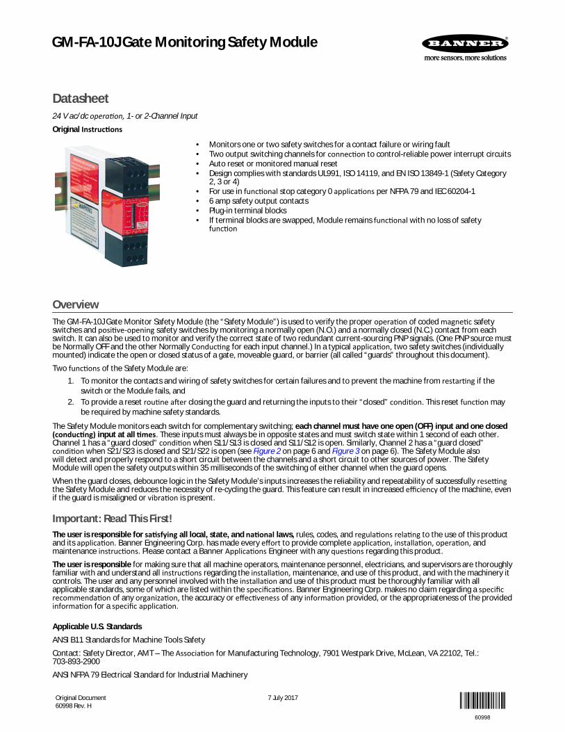
Datasheet24 V ac/dc operation, 1- or 2-Channel InputOriginal Instructions
• Monitors one or two safety switches for a contact failure or wiring fault• Two output switching channels for connection to control-reliable power interrupt circuits• Auto reset or monitored manual reset• Design complies with standards UL991, ISO 14119, and EN ISO 13849-1 (Safety Category
2, 3 or 4)• For use in functional stop category 0 applications per NFPA 79 and IEC 60204-1• 6 amp safety output contacts• Plug-in terminal blocks• If terminal blocks are swapped, Module remains functional with no loss of safety
function
OverviewThe GM-FA-10J Gate Monitor Safety Module (the “Safety Module”) is used to verify the proper operation of coded magnetic safetyswitches and positive-opening safety switches by monitoring a normally open (N.O.) and a normally closed (N.C.) contact from eachswitch. It can also be used to monitor and verify the correct state of two redundant current-sourcing PNP signals. (One PNP source mustbe Normally OFF and the other Normally Conducting for each input channel.) In a typical application, two safety switches (individuallymounted) indicate the open or closed status of a gate, moveable guard, or barrier (all called “guards” throughout this document).Two functions of the Safety Module are:
1. To monitor the contacts and wiring of safety switches for certain failures and to prevent the machine from restarting if theswitch or the Module fails, and
2. To provide a reset routine after closing the guard and returning the inputs to their “closed” condition. This reset function maybe required by machine safety standards.
The Safety Module monitors each switch for complementary switching; each channel must have one open (OFF) input and one closed(conducting) input at all times. These inputs must always be in opposite states and must switch state within 1 second of each other.Channel 1 has a “guard closed” condition when S11/S13 is closed and S11/S12 is open. Similarly, Channel 2 has a “guard closed”condition when S21/S23 is closed and S21/S22 is open (see Figure 2 on page 6 and Figure 3 on page 6). The Safety Module alsowill detect and properly respond to a short circuit between the channels and a short circuit to other sources of power. The SafetyModule will open the safety outputs within 35 milliseconds of the switching of either channel when the guard opens.When the guard closes, debounce logic in the Safety Module’s inputs increases the reliability and repeatability of successfully resettingthe Safety Module and reduces the necessity of re-cycling the guard. This feature can result in increased efficiency of the machine, evenif the guard is misaligned or vibration is present.
Important: Read This First!The user is responsible for satisfying all local, state, and national laws, rules, codes, and regulations relating to the use of this productand its application. Banner Engineering Corp. has made every effort to provide complete application, installation, operation, andmaintenance instructions. Please contact a Banner Applications Engineer with any questions regarding this product.The user is responsible for making sure that all machine operators, maintenance personnel, electricians, and supervisors are thoroughlyfamiliar with and understand all instructions regarding the installation, maintenance, and use of this product, and with the machinery itcontrols. The user and any personnel involved with the installation and use of this product must be thoroughly familiar with allapplicable standards, some of which are listed within the specifications. Banner Engineering Corp. makes no claim regarding a specificrecommendation of any organization, the accuracy or effectiveness of any information provided, or the appropriateness of the providedinformation for a specific application.
Applicable U.S. StandardsANSI B11 Standards for Machine Tools SafetyContact: Safety Director, AMT – The Association for Manufacturing Technology, 7901 Westpark Drive, McLean, VA 22102, Tel.:703-893-2900ANSI NFPA 79 Electrical Standard for Industrial Machinery
GM-FA-10J Gate Monitoring Safety Module
Original Document60998 Rev. H
7 July 2017
60998
Contact: National Fire Protection Association, 1 Batterymarch Park, P.O. Box 9101, Quincy, MA 02269-9101, Tel.: 800-344-3555ANSI/RIA R15.06 Safety Requirements for Industrial Robots and Robot SystemsContact: Robotic Industries Association, 900 Victors Way, P.O. Box 3724, Ann Arbor, MI 48106, Tel.: 734-994-6088
Applicable International StandardsEN ISO 12100 Safety of Machinery – Basic Concepts, General Principles for DesignEN 60204-1 Electrical Equipment of Machines Part 1: General RequirementsEN ISO 13849-1 Safety-Related Parts of Control SystemsEN 13855 (EN 999) The Positioning of Protective Equipment in Respect to Approach Speeds of Parts of the Human BodyISO 14119 (EN 1088) Interlocking Devices Associated with Guards – Principles for Design and SelectionAlso, request a type “C” standard for your specific machinery.Contact: Global Engineering Documents, 15 Inverness Way East, Englewood, CO 80112-5704, Tel.: 800-854- 7179
Certificate of AdequacyThis Safety Module datasheet (p/n 60998) satisfies the requirements of Machinery Directive 2006/42/EC, Section 1.7.4 — instructions.
Safety Circuit Integrity and EN ISO 13849-1 Safety Circuit PrinciplesSafety circuits involve the safety-related functions of a machine that minimize the level of risk of harm. These safety-related functionscan prevent initiation, or they can stop or remove a hazard. The failure of a safety-related function or its associated safety circuit usuallyresults in an increased risk of harm.The integrity of a safety circuit depends on several factors, including fault tolerance, risk reduction, reliable and well-tried components,well-tried safety principles, and other design considerations.Depending on the level of risk associated with the machine or its operation, an appropriate level of safety circuit integrity (performance)must be incorporated into its design. Standards that detail safety performance levels include ANSI B11.19 Performance Criteria forSafeguarding and EN ISO 13849-1 Safety-Related Parts of a Control System.
Safety Circuit Integrity LevelsSafety circuits in International and European standards have been segmented into categories, depending on their ability to maintaintheir integrity in the event of a failure. The most recognized standard that details safety circuit integrity levels is EN ISO 13849-1, whichestablishes five levels: Categories B, 1, 2, 3, and the most stringent, Category 4.In the United States, the typical level of safety circuit integrity has been called ”control reliability.” Control reliability typicallyincorporates redundant control and self-checking circuitry and has been loosely equated to EN ISO 13849-1 Categories 3 and 4 (see CSAZ432 and ANSI B11.TR4).If the requirements described by EN ISO 13849-1 are to be implemented, a risk assessment must first be performed to determine theappropriate category, in order to ensure that the expected risk reduction is achieved. This risk assessment must also take into accountnational regulations, such as U.S. control reliability or European “C” level standards, to ensure that the minimum level of performancethat has been mandated is complied with.
Fault ExclusionAn important concept within the category requirements of EN ISO 13849-1 is the probability of the occurrence of the failure, which canbe decreased using the "fault exclusion" method. This method assumes that the possibility of certain well-defined failure(s) can bereduced to a point where the resulting fault(s) can be disregarded.Fault exclusion is a tool a designer can use during the development of the safety-related part of the control system and the riskassessment process. It allows the designer to eliminate the possibility of various failures and justify it through the risk assessmentprocess to meet the requirements of Categories 2, 3, or 4. See EN ISO 13849-1/-2 for further information.
GM-FA-10J Gate Monitoring Safety Module
2 www.bannerengineering.com - Tel: +1-763-544-3164 P/N 60998 Rev. H
Configuration
S21A1
S11 S13
S23 S21 S22
13 23 Y1
Y2 14 24 A2
K1
K2
14 24
MachineSafety
GM-FA-10J
Power
Fault
In 1
In 2
Output
Power ON(green)
Input 1Active (green)
Fault (red)
Input 2Active (green)
OutputsActive (green)
S12 S13 S11
Y12313 A1
A2 2414Y2
S22 S21 S23
Figure 1. GM-FA-10J Features and Terminal Locations
The Safety Module may be configured via DIP switches for two-channel(redundant switches on a single guard), or one-channel operation (individualswitches on two guards). In two-channel operation, each channel (S11/S12/S13and S21/S22/S23) must switch within 3-second simultaneity of the other whenthe guard closes. If not, the guard must be re-opened and closed until the timingrequirement is met. When the guard opens, the two channels operateconcurrently (both channels must switch, but without the timing requirement).In one-channel operation, each channel operates individually, except to resetthe device (in which case both guards must be closed). If only one switch is beingmonitored, the closed input of the unused channel must be jumpered (S11/S13 orS21/S23).The reset function has two options, selected by DIP switch: Automatic reset orMonitored Manual reset. See Figure 7 on page 8 for configuration information.The reset input also can be used for an External Device Monitoring (EDM) circuit.The EDM circuit consists of a normally closed, force-guided contact from eachdevice being controlled by the Safety Module, all wired in series with the Resetbutton (if used) and terminated at terminals Y1 and Y2. See Figure 6 on page 8for further information.The output of the Safety Module consists of two redundant output switchingchannels, each of which is the series connection of two forced-guided relaycontacts (K1 and K2 in Figure 6 on page 8). Each of the switching outputs israted for up to 250V ac at up to 6 amps.
WARNING: Hazard PointIt must not be possible for personnel to reach any hazard point through an opened guard (or any opening) beforehazardous machine motion has completely stopped.Please reference OSHA CFR 1910.217 and ANSI B11 standards for information on determining safety distances andsafe opening sizes for your guarding devices.
WARNING: Risk AssessmentThe level of safety circuit integrity can be greatly affected by the design and installation of the safety devices andthe means of interfacing of those devices. A risk assessment must be performed to determine the appropriatelevel of safety circuit integrity to ensure the expected risk reduction is achieved and all relevant regulations andstandards are complied with.
Safety Interlock Switch RequirementsThe following general requirements and considerations apply to the installation of interlocked guards and gates for the purpose ofsafeguarding. In addition, the user must refer to the relevant regulations to ensure compliance with all necessary requirements.Hazards guarded by the interlocked guard must be prevented from operating until the guard is closed; a stop command must be issuedto the guarded machine if the guard opens while the hazard is present. Closing the guard must not, by itself, initiate hazardous motion;a separate procedure must be required to initiate the motion. The safety interlock switches must not be used as a mechanical or end-of-travel stop.The guard must be located an adequate distance from the danger zone (so that the hazard has time to stop before the guard is openedsufficiently to provide access to the hazard), and it must open either laterally or away from the hazard, not into the safeguarded area.The guard also should not be able to close by itself and activate the interlocking circuitry. In addition, the installation must preventpersonnel from reaching over, under, around, or through the guard to the hazard. Any openings in the guard must not allow access tothe hazard (see OSHA 29CFR1910.217 Table O-10, ANSI B11.19, ISO 13857, ISO14120/EN953 or the appropriate standard). The guardmust be strong enough to contain hazards within the guarded area, which may be ejected, dropped, or emitted by the machine.The safety interlock switches, actuators, sensors, and magnets must be designed and installed so that they cannot be easily defeated.They must be mounted securely so that their physical position cannot shift, using reliable fasteners that require a tool to remove them.Mounting slots in the housings are for initial adjustment only; final mounting holes must be used for permanent location.
GM-FA-10J Gate Monitoring Safety Module
P/N 60998 Rev. H www.bannerengineering.com - Tel: +1-763-544-3164 3
WARNING: Perimeter Guarding ApplicationsIf the application may result in a pass-through hazard (for example, perimeter guarding), either the safeguardingdevice or the guarded machine's MSCs/MPCEs must cause a Latched response following a Stop command (forexample, interruption of the sensing field of a light curtain, or opening of an interlocked gate/guard). The reset ofthis Latched condition may only be achieved by actuating a reset switch that is separate from the normal means ofmachine cycle initiation. The switch must be positioned as described in this document.Lockout/Tagout procedures per ANSI Z244.1 may be required, or additional safeguarding, as described by ANSI B11safety requirements or other appropriate standards, must be used if a passthrough hazard cannot be eliminated orreduced to an acceptable level of risk. Failure to observe this warning may result in serious bodily injury or death.
Coded Magnetic Safety SwitchesSimilar to positive-opening safety switches, coded magnetic switches used with the Safety Module must provide one normally closedcontact and one normally open contact (typically a four-wire switch). The sensor and its magnet must be mounted a minimum distanceof 15 mm (0.6 inches) from any magnetized or ferrous materials for proper operation. If either the sensor or magnet is mounted on amaterial that can be magnetized (a ferrous metal, such as iron), the switching distance will be affected. Although the sensor and magnetare coded to minimize the possibility of false actuation, they should not be used within known fields of high-level electromagneticradiation.Depending on the model of sensor and magnet used, the installation must be designed to provide the correct direction of approach. Thespeed of approach must be fast enough to meet the simultaneity-monitoring period of 1.0 second, approximately equal to or greaterthan 0.1 m (4 inches) per second. If the simultaneity requirement is not met, the Safety Module can not be reset and will not close itssafety output contacts.
Positive-Opening Interlocking SwitchesSafety interlock switches used with the Safety Module must satisfy several requirements. Each switch must provide electrically isolatedcontacts: at minimum, one normally closed (N.C.) contact or normally conducting source and one normally open (N.O.) contact ornormally OFF source to interface with the Module.The contacts must be of “positive-opening” design, with one or more normally closed contacts rated for safety. Positive-openingoperation causes the switch to be forced open, without the use of springs, when the switch actuator is disengaged or moved from itshome position (see the Banner Catalog for examples). In addition, the switches must be mounted in a “positive mode,” to move/disengage the actuator from its home position and open the normally closed contact, when the guard opens.
Switch Wiring for Typical ApplicationsRequirements vary widely for the level of control reliability or safety category (per EN ISO 13849) in the application of interlockedguards. Although Banner Engineering always recommends the highest level of safety in any application, it is the responsibility of theuser to safely install, operate, and maintain each safety system and comply with all relevant laws and regulations. The applicationsshown in Figure 2 on page 6 through Figure 4 on page 7 meet or exceed the requirements for control reliability and SafetyCategory 3 or 4, per EN ISO 13849.
Mechanical InstallationThe Safety Module must be installed inside an enclosure.It is not designed for exposed wiring. It is the user’s responsibility to house the Safety Module in an enclosure with NEMA 3 (IEC IP54)rating, or better. The Safety Module mounts directly to standard 35 mm DIN rail.Heat Dissipation Considerations: For reliable operation, ensure that the operating specifications are not exceeded. The enclosure mustprovide adequate heat dissipation, so that the air closely surrounding the Module does not exceed the maximum operatingtemperature stated in the Specifications. Methods to reduce heat build-up include venting, forced airflow (for example, exhaust fans),adequate enclosure exterior surface area, and spacing between modules and other sources of heat.
Electrical InstallationEach Safety Module is powered by 24 V ac/dc (at less than 150 mA). The Safety Module, in turn, supplies power to each switch.It is not possible to give exact wiring instructions for a Safety Module that interfaces to a multitude of machine control configurations.The following guidelines are general in nature.The Safety Module has no delay function. Its output relay contacts open within 35 milliseconds after a safety input opens. This classifiesthe Safety Module as a functional stop "Category 0" control, as defined by ANSI NFPA 79 and IEC/EN 60204-1.
GM-FA-10J Gate Monitoring Safety Module
4 www.bannerengineering.com - Tel: +1-763-544-3164 P/N 60998 Rev. H
WARNING: Shock Hazard and Hazardous EnergyAlways disconnect power from the safety system (for example, device, module, interfacing, etc.) and themachine being controlled before making any connections or replacing any component.Electrical installation and wiring must be made by Qualified Personnel1 and must comply with the relevantelectrical standards and wiring codes, such as the NEC (National Electrical Code), ANSI NFPA79, or IEC 60204-1, andall applicable local standards and codes.Lockout/tagout procedures may be required. Refer to OSHA 29CFR1910.147, ANSI Z244-1, ISO 14118, or theappropriate standard for controlling hazardous energy.
Connecting Power to the Safety ModuleThe Safety Module requires a 24 V ac/dc supply voltage (see Specifications). Use extreme caution when installing ac power. Use aminimum of 16 to 18 AWG wire for power and output connections. Use a minimum of 20 AWG wire for all other terminal connections.A hand-operated supply disconnect and over-current protection (e.g., a circuit breaker) must be provided per ANSI NFPA79 and IEC/EN60204-1.
Monitoring Series-Connected Safety SwitchesWhen monitoring two individually mounted safety switches (as shown in Figure 2 on page 6 through Figure 4 on page 7), a faultyswitch will be detected if it fails to switch as the guard opens. In this case, the Gate Monitor Module will de-energize its output relaysand disable its reset function until the input requirements are met (i.e., the faulty switch is replaced). However, when a series ofinterlocking safety switches is monitored by a single Safety Module, the failure of one switch in the system may be masked or notdetected at all (refer to Figure 5 on page 7 and Figure 6 on page 8).Series-connected interlock switch circuits do not meet EN ISO 13849 Safety Category 4 and may not meet Control Reliabilityrequirements because of the potential for an inappropriate Gate Monitor reset or a potential loss of the safety stop signal. A multipleconnection of this type should not be used in applications where loss of the safety stop signal or an inappropriate reset can leadpotentially to serious injury or death. The following two scenarios assume two positive-opening safety switches on each guard:
1. Masking of a failure. If a guard is opened but a switch fails to open, the redundant safety switch will open and cause the SafetyModule to de-energize its outputs. If the faulty guard is then closed, both Safety Module input channels also close, but becauseone channel did not open, the Safety Module will not reset. However, if the faulty switch is not replaced and a second “good”guard is cycled (opening and then closing both of the Module’s input channels), the Module considers the failure to becorrected. With the input requirements apparently satisfied, the Module allows a reset. This system is no longer redundant and,if the second switch fails, may result in an unsafe condition (i.e., the accumulation of faults results in the loss of the safetyfunction).
2. Non-detection of a failure. If a good guard is opened, the Safety Module de-energizes its outputs (a normal response). But if afaulty guard is then opened and closed before the good guard is re-closed, the failure on the faulty guard is not detected. Thissystem is no longer redundant and may result in a loss of safety if the second safety switch fails to switch when needed.
The systems in either scenario do not inherently comply with the safety standard requirements of detecting single faults and preventingthe next cycle. In multiple-guard systems using series-connected safety switches, it is important to periodically check the functionalintegrity of each interlocked guard individually. Operators, maintenance personnel, and others associated with the operation of themachine must be trained to recognize such failures and be instructed to correct them immediately.Open and close each guard separately while verifying that the Gate Monitor outputs operate correctly throughout the check procedure.Follow each gate closure with a manual reset, if needed. If a contact set fails, the Safety Module will not enable its reset function. If theSafety Module does not reset, a switch may have failed; that switch must be immediately replaced.This check must be performed and all faults must be cleared, at a minimum, during periodic checkouts. If the application can notexclude these types of failures and such a failure could result in serious injury or death, then the series connection of safety switchesmust not be used.
WARNING: Multiple Switching DevicesWhenever two or more devices are connected to the same safety module (controller):
• Contacts of the corresponding pole of each switch must be connected together in series. Never connectthe contacts of multiple switches in parallel. Such a parallel connection defeats the switch contactmonitoring ability of the Module and creates an unsafe condition which may result in serious injury ordeath.
• Each device must be individually actuated (engaged), then released (or re-armed) and the safety modulereset. This allows the module to check each switch and its wiring to detect faults.
This check must be performed during the prescribed checkouts. Failure to test each device individually in thismanner may result in undetected faults and create an unsafe condition which may result in serious injury ordeath.
1 A person who, by possession of a recognized degree or certificate of professional training, or who, by extensive knowledge, training and experience, has successfully demonstrated the abilityto solve problems relating to the subject matter and work.
GM-FA-10J Gate Monitoring Safety Module
P/N 60998 Rev. H www.bannerengineering.com - Tel: +1-763-544-3164 5
Connecting to the Guarded MachineThe machine interface wiring diagram shows a generic connection of the Module’s two redundant output circuits to machine primarycontrol elements MPCE1 and MPCE2. A machine primary control element is an electrically powered device, external to the Module,which stops the guarded machinery by immediately removing electrical power to the machine and (when necessary) by applyingbraking to dangerous motion. The stop is accomplished by removing power to the actuator coil of either MPCE.To satisfy the Safety Category 4 requirements of EN ISO 13849, each MPCE must offer a normally closed, forced-guided monitor contact.One normally closed monitor contact from each MPCE is wired in series to the Y1-Y2 feedback/reset input (see Figure 7 on page 8).In operation, if one of the switching contacts of either MPCE fails in the shorted condition, the associated monitor contact will remainopen, preventing the reset of the Module.
External Device MonitoringTo satisfy the requirements of Control Reliability (OSHA and ANSI) and Category 3 and 4 of EN ISO 13849-1, the machine primary controlelements (MPCEs) must each offer a normally closed, forced-guided (mechanically linked) monitor contact. Connect one normally closedmonitor contact from each master stop control element in series to Y1 and Y2 (see wiring diagrams).In operation, if one of the switching contacts of either MPCE fails in the energized condition, the associated monitor contact will remainopen. Therefore, it will not be possible to reset the Safety Module. If no MPCE-monitor contacts are monitored, a jumper must beinstalled between terminals Y1 and Y2 (dotted line), as shown in the hookup drawings. It is the user’s responsibility to ensure that anysingle failure will not result in a hazardous condition and will prevent a successive machine cycle.
Connecting Safety Switches
Mechanical stop
Guard #1open
Guard #2open
BlueGray
Black
Brown
SI-MAG..SM SI-MAG..MM
SI-MAG..SM SI-MAG..MM
Mechanical stop
BlueGrayBlack
Brown
NOTE: If only one magnetic safety switch is used, select 1-channel input and jumper S23 to S21.
S12 S13S11
S23 S22S21
Figure 2. Wiring to two 4-wire coded magnetic safety switches.Configured for one-channel monitoring of either one or two guards
(jumper S11/S13 or S21/S23 for one-channel), this application isconsidered to meet or exceed requirements for Control Reliability and
Safety Categories 3 and 4 per EN ISO 13849-1.
Guard
Mechanicalstop
Mechanicalstop
open
S12 S13S11
S23 S22S21
Guard #1
NOTE: Guard shown in closed position.
Figure 3. Wiring to two positive-opening safety interlock switches.Configured for two-channel monitoring of one guard, this application isconsidered to meet or exceed requirements for Control Reliability and
Safety Categories 3 and 4 per EN ISO 13849-1.
GM-FA-10J Gate Monitoring Safety Module
6 www.bannerengineering.com - Tel: +1-763-544-3164 P/N 60998 Rev. H
S12 S13
S23 S22
NOTE: If PNP current-sourcing signals are used, the GM-FA-10J and the current-sourcing devices must be powered from the same DC supply and Common (Com).
A1
A2
+24 V dc
0 V
+24 V dc
+24 V dc
N.O.
N.C.
N.O.
N.C.
0 V
0 V
Fuse*
* 500 mA slow blow fuse recommended
Figure 4. Wiring to two complementary current-sourcing PNP devices.Configured for either one-channel or two-channel monitoring, the level of
safety (Control Reliability or Safety Categories) is dependent on thedevices connected to the GM-FA-10J.
One-Channel Monitoring
Configured for one-channel monitoring of multiple guards withsingle switches at each guard (see Warning). Up to 10 Bannermagnetic switches may be connected to each channel in thisseries/parallel method.
WARNING: Not a Safety Category 4Application. When monitoring multipleguards with a series connection of multiplesafety interlock switches, a single failuremay be masked or not detected at all.When such a configuration is used,procedures must be performed regularly toverify proper operation of each switch. See“Monitoring Series- Connected SafetySwitches” for more information.
(If other than Banner magnetic switches are used, a totalresistance of 270 Ohms between S11/S13, S11/S12, S21/S22 andS21/S23 must not be exceeded.)
Blue
Gray
Blac
k
Brow
n
Blue
Gray
Blac
k
Brow
n
Blue
Gray
Blac
k
Brow
n
Blue
Gray
Blac
k
Brow
n
Blue
Gray
Blac
k
Brow
n
Blue
Gray
Blac
k
Brow
n
S12 S13S11
S23 S22S21
SI-MAG..SM SI-MAG..SM SI-MAG..SM
Guard #1 Guard #2 Guard #n
SI-MAG..SM SI-MAG..SM SI-MAG..SM
Guard #3 Guard #4 Guard #n+1
NOTE: Switch/magnet pairs shown in closed position.
Mechanical stop
Mechanical stop
SI-MAG..MMSI-MAG..MM SI-MAG..MM
SI-MAG..MM SI-MAG..MM SI-MAG..MM
Figure 5. Alternate wiring for one-channel monitoring of multiple guards
GM-FA-10J Gate Monitoring Safety Module
P/N 60998 Rev. H www.bannerengineering.com - Tel: +1-763-544-3164 7
Two-Channel Monitoring
Configured for two-channel monitoring of multiple guards withtwo safety switches mounted individually on each guard (seeWarning).The number of mechanical switches is limited by the max.resistance of 270 ohm between S11/S13, S11/S12, S21/S22 andS21/S23. The total resistance is calculated by adding theresistance of all guard switch contacts and the resistance of thecables that connect the switches and the switches to the module.
WARNING: Not a Safety Category 4Application. When monitoring multipleguards with a series connection of multiplesafety interlock switches, a single failuremay be masked or not detected at all.When such a configuration is used,procedures must be performed regularly toverify proper operation of each switch. See“Monitoring Series- Connected SafetySwitches” for more information.
Guard #1 Guard #2 Guard #3 Guard #n
NOTE: Guards shown in closed position.
S12 S13S11
S23 S22S21
Guard #4
Figure 6. Alternate wiring for two-channel monitoring of multiple guards
WARNING: Interfacing MPCEs. NEVER wire an intermediate device(s) (e.g., PLC, PES, PC), between the SafetyModule outputs and the machine primary control element (MPCE) it switches, in such a manner that in the event ofa failure there is the loss of the safety stop command, OR in such a manner that the safety function can besuspended, overridden, or dereated, unless accomplished with the same or greater degree of safety. Wheneverforced-guided, mechanically linked relays are added as intermediate switching devices, a normally closed forced-guided monitor contact from each relay must be added to the series feedback loop between Safety Moduleterminals Y1 and Y2.
WARNING: Wiring of Arc SuppressorsIf arc suppressors are used, they MUST beinstalled as shown across the actuator coil ofthe stop control elements (MSCs or MPCEs).NEVER install suppressors directly across theoutput contacts of the Safety Device orModule. It is possible for suppressors to fail as ashort circuit. If installed directly across theoutput contacts, a short-circuited suppressorcreates an unsafe condition which may resultin serious injury or death.
*
*
* Arc Suppressor, see Warning
A1 Y1
24 V ac/dc
MACHINECONTROL
RESET
S12 S13S11
S23 S22S21
2313
Y2 A22414
K1
K2
0 V ac/dc
MPCE2Monitoring Contactsor Jumper
MPCE1 MPCE1
For Automatic Reset, connect directly and configure DIP switches
MPCE2
Fuse**
** 500 mA slow blow fuse recommended
Figure 7. Wiring to the guarded machine
GM-FA-10J Gate Monitoring Safety Module
8 www.bannerengineering.com - Tel: +1-763-544-3164 P/N 60998 Rev. H
Overvoltage Category II and III Installations (EN 50178 and IEC 60664-1)The Safety Module is rated for Overvoltage Category III when voltages of 1 V to 150 V ac/dc are applied to the output relay contacts. It israted for Overvoltage Category II when voltages of 151 V to 250 V ac/dc are applied to the output relay contacts and no additionalprecautions are taken to attenuate possible overvoltage situations in the supply voltage. The Module can be used in an OvervoltageCategory III environment (with voltages of 151 V to 250 V ac/dc) if care is taken either to reduce the level of electrical disturbances seenby the Module to Overvoltage Category II levels by installing surge suppressor devices (for example, arc suppressors), or to install extraexternal insulation in order to isolate both the Safety Module and the user from the higher voltage levels of a Category III environment.For Overvoltage Category III installations with applied voltages from 151 V to 250 V ac/dc applied to the output contact(s): the SafetyModule may be used under the conditions of a higher overvoltage category where appropriate overvoltage reduction is provided.Appropriate methods include:
• An overvoltage protective device• A transformer with isolated windings• A distribution system with multiple branch circuits (capable of diverting energy of surges)• A capacitance capable of absorbing energy of surges• A resistance or similar damping device capable of dissipating the energy of surges
When switching inductive ac loads, it is good practice to protect the Safety Module outputs by installing appropriately-sized arcsuppressors. However, if arc suppressors are used, they must be installed across the load being switched (for example, across the coilsof external safety relays), and never across the Safety Module’s output contacts (see WARNING, Arc Suppressors).
ConfigurationWARNING: Reset Routine RequiredU.S. and international standards require that a reset routine be performed after clearing the cause of a stopcondition (for example, arming an E-stop button, closing an interlocked guard, etc.). Allowing the machine torestart without actuating the normal start command/device can create an unsafe condition which may result inserious injury or death.
WARNING: Reset Switch LocationAll reset switches must be accessible only from outside, and in full view of, the hazardous area. Reset switchesmust also be out of reach from within the safeguarded space, and must be protected against unauthorized orinadvertent operation (for example, through the use of rings or guards). If any areas are not visible from the resetswitch(es), additional means of safeguarding must be provided. Failure to do so may result in serious bodily injuryor death.
To remove a terminal block, insert a small flat-blade screwdriver into the slot atthe center of the block as shown (may be covered by label). As typically mountedon a DIN rail, to remove the top block, rotate the screw driver downwards(towards the module) and pry to loosen. The terminal block will slide outwards(towards you) as it loosens. To remove the lower block, rotate the screw driverupwards (towards the module) and pry to loosen.When reinserting the block, take care to slide the dovetail on the terminal blockinto the slot on the frame.
Figure 8. Removal of terminal blocks
GM-FA-10J Gate Monitoring Safety Module
P/N 60998 Rev. H www.bannerengineering.com - Tel: +1-763-544-3164 9
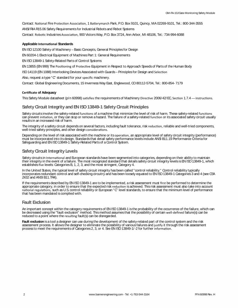
Manual Reset and Reset Switch Connection
The reset switch must be capable of reliably switching 15 to 30V dc at 5 to 50 mA. Asshown in Figure 7 on page 8, the reset switch connects between terminals Y1 and Y2 of theModule. The reset switch must be located outside of – and not accessible from – the areaof dangerous motion, and it must be positioned so the switch operator can see all areas ofdangerous motion during the reset procedure (see Warning).To configure the Module for Manual Reset, set switches S1.2 and S2.2 in banks A and B toOFF. The reset switch may be any mechanical normally open switch, but should be amomentary switch or a two-position keyed switch. To reset the Module, both guards mustbe closed, at which time the output LED will flash (signaling that the reset switch must becycled). This action is a monitored manual reset (open-closed-open), where the “closed”phase is approximately 0.25 to 2 seconds long.
S21A1
S11 S13
S23 S21 S22
13 23 Y1
Y2 14 24 A2
K1
K2
14 24
MachineSafety
GM-FA-10J
Power
Fault
In 1
In 2
Output
DIP Switch
Bank "A"S1.1S1.2
DIP Switch
Bank "B"S2.1S2.2
S1.1/S2.1 OFF* – 2-Channel ON – 1-Channel
S1.2/S2.2 OFF* – Manual Reset ON – Auto Reset
* Factory Default
NOTE: Corresponding DIP switches in Banks A and B must be set identically.
OFFON
Shown withterminal blocksremoved
Figure 9. DIP switch configuration settings forreset mode and 1- or 2-channel operation
Automatic Reset ModeTo configure the Module for Automatic Reset, set switches S1.2 and S2.2 in Banks A and B to ON. If no MPCE contacts are monitored,install a jumper between terminals Y1 and Y2 (see Figure 7 on page 8). The Safety Module will reset (and its outputs will energize) assoon as the guards return to their closed position.Automatic Reset is useful for some automated processes. However, if Automatic Reset is used, an alternate means must be provided toprevent resumption of hazardous machine motion until an alternate reset procedure is performed. The alternate means must include aReset switch, located outside the area of dangerous motion, and positioned so that the switch operator can see all areas of dangerousmotion during the reset procedure.
1-Channel or 2-Channel InputThe Safety Module may be configured for 1-channel or 2-channel operation by setting DIP switches S1.1 and S2.1 in Banks A and B. In 1-channel operation (S1.1 and S2.1 – ON), the input channels function independently. The two guards can be monitored individually, butboth channels must be in the closed position for the Safety Module to be reset.In 2-channel operation ( S1.1 and S2.1 – OFF) the input channels must function together. Both channels must switch within a 3-secondsimultaneity of the other when the guard closes. If not, the guard must be re-opened and closed until the timing requirement is met.When the guard opens, the channels function concurrently (both must open, but without the timing requirement).In either configuration, the “closed” inputs of each channel must be closed before the Safety Module can be reset (continuity S11 to S13and S21 to S23). If in 1-channel mode and monitoring only one switch, a jumper must be installed at the unused input (e.g., S21 to S23;see Figure 2 on page 6).
Troubleshooting and Maintenance
Initial Checkout Procedure
CAUTION: Disconnect Power Prior to CheckoutBefore performing the initial checkout procedure, make certain all power is disconnected from the machine tobe controlled.Dangerous voltages may be present along the Safety Module wiring barriers whenever power to the machinecontrol elements is On. Exercise extreme caution whenever machine control power is or may be present. Alwaysdisconnect power to the machine control elements before opening the enclosure housing of the Safety Module.
GM-FA-10J Gate Monitoring Safety Module
10 www.bannerengineering.com - Tel: +1-763-544-3164 P/N 60998 Rev. H
WARNING: Multiple Safety DevicesWhen two or more safety devices are used, each device must be individually actuated, causing a Stop or open-contact condition, then reset/rearmed and the Safety Module reset (if using manual reset mode). This allows themonitoring circuits to check each device and its wiring to detect faults. Failure to test each device individually inthis manner may result in undetected faults and create an unsafe condition which may result in serious injury ordeath.
1. Remove power from the machine primary control elements (MPCEs).2. Close all monitored guards. If the Module is wired to 1-channel input, the second input (S21/S23 or S11/S13) must be jumpered
if unused.3. Apply input power (only) to the Gate Monitor Module at terminals A1 and A2 (see Figure 7 on page 8). The following LEDs
should come ON: Power, Input 1, Input 2If the Power LED comes ON, but either or both Input LEDs are not ON, disconnect input power and check the wiring of theconnected switch(es) and/or the jumper. Check if the jumper is installed correctly on the unused input. Return to step 2 afterthe cause of the problem has been corrected.
4. Step 4 varies, depending on how the module is configured.Option Description
If the Module is set to 1-channel operation
After the Power, Input 1, and Input 2 LEDs all are ON, open and close all connected guards oneat a time. When each individual guard opens, the corresponding Input LED must turn OFF, andwhen the guard closes its LED must come ON again.
If the Module is set to 2-channel operation
After the Power, Input 1, and Input 2 LEDs all are ON, open the guard; both switches mustopen within 3 seconds, and both Input LEDs must turn OFF. If the red Fault LED comes ON,simultaneity between the switches or within one switch (between its NO and NC contacts) wasnot met. Check all wiring and the switches.
If the Module is set to AutoReset
(Y1/Y2 closed and DIP switches set to Auto Reset), the output LED will come ON as soon asboth Input LEDs are ON (output contacts 13/14 and 23/24 close).
If the Module is set toManual Monitored Reset
The Output LED should come ON only if Input 1 and 2 LEDs are ON and the Reset buttonconnected to Y1 and Y2 went from open to closed and back to open position.
5. Repeat step 4 individually for each guard that is being monitored.6. Close the guard. Apply power to the machine control elements and perform the Periodic Checks on page 11.
NOTE: Make sure that both Input 1 and 2 LEDs are ON only when ALL connected guards are closed. If the guards are closed andthe Input LEDs are OFF, the guard switches may be wired incorrectly, which could reset the Module inappropriately (safetyoutput contacts close as soon as one of the connected guards opens).
Do not continue operation until all checks are completed and all problems are corrected. See Do Not Use Machine Until System isWorking Properly warning, and Repairs on page 12 and Troubleshooting on page 12 for further information.
Periodic Checks
WARNING: Do Not Use Machine Until System Is Working ProperlyIf all of these checks cannot be verified, do not attempt to use the safety system that includes the Banner deviceand the guarded machine until the defect or problem has been corrected. Attempts to use the guarded machineunder such conditions may result in serious bodily injury or death.
At each shift change or machine setup, a Designated Person* should perform the following checks on all safety switches:
1. Verify the switch, sensor, actuator, or magnet are not broken or damaged.2. Check for good alignment between the switch and actuator or sensor and magnet.3. Confirm the switches are not being used as an end-of-travel stop.4. Correct any loosened mounting hardware.5. Verify it is not possible to reach any hazard point through an opened guard (or any opening) before hazardous machine motion
stops completely.6. Open and close each guard separately while verifying that the Gate Monitor outputs operate correctly throughout the check
procedure. Follow each gate closure with a manual reset, if needed. If a contact set fails, the Safety Module will not enable itsreset function. If the Safety Module does not reset, a switch may have failed; that switch must be immediately replaced.
7. In addition, a Qualified Person* should perform the following on a periodic schedule (determined by the user, based upon theseverity of the environment and the frequency of switch actuations):a) Inspect the electrical wiring for continuity and damage.b) Confirm that the wiring conforms to the instructions given in this installation manual.
GM-FA-10J Gate Monitoring Safety Module
P/N 60998 Rev. H www.bannerengineering.com - Tel: +1-763-544-3164 11
Do not continue operation until all checks are completed and all problems are corrected. See Repairs on page 12 and Troubleshootingon page 12 for further information.* A Designated Person is identified in writing by the employer as being appropriately trained to perform a specified checkout procedure.A Qualified Person possesses a recognized degree or certificate or has extensive knowledge, training, and experience to be able to solveproblems relating to safety switch installation.
RepairsContact Banner Engineering for troubleshooting of this device. Do not attempt any repairs to this Banner device; it contains no field-replaceable parts or components. If the device, device part, or device component is determined to be defective by a BannerApplications Engineer, they will advise you of Banner's RMA (Return Merchandise Authorization) procedure.
Important: If instructed to return the device, pack it with care. Damage that occurs in return shipping is not coveredby warranty.
CAUTION: Abuse of Module After FailureIf an internal fault has occurred and the Module will not reset, do not tap, strike, or otherwise attempt to correctthe fault by a physical impact to the housing. An internal relay may have failed in such a manner that itsreplacement is required.If the Module is not immediately replaced or repaired, multiple simultaneous failures may accumulate such thatthe safety function can not be guaranteed.
TroubleshootingModel GM-FA-10J Gate Monitoring Safety Module provides five LED indicators.
LED Condition Meaning
Power (green) ON Power is connected to terminals A1-A2.
OFF No power or low power to terminals A1-A2, or internal power supply failure.
Fault (red) ON External fault or configuration fault. The corresponding function LED will flash to indicate thearea where the fault has been detected. See Clearing Faults on page 12 for probable cause.
Flashing Internal Fault. See Repairs on page 12.
Flashing (along with the Power LEDflashing)
DIP Switch configuration fault. Check that switch positions are the same for both Banks A andB.
Input 1(green)
ON Guard 1 is closed and the inputs of Channel 1 are satisfied.
OFF Guard 1 is open or the inputs of Channel 1 are not satisfied.
Flashing (along with the Fault LEDON)
See Clearing Faults on page 12 for probable cause.
Input 2(green)
ON Guard 2 is closed and the inputs of Channel 2 are satisfied.
OFF Guard 2 is open or the inputs of Channel 2 are not satisfied.
Flashing (along with the Fault LEDON)
See Clearing Faults on page 12 for probable cause.
Output(green)
ON Both internal relays K1 and K2 are energized (13/14 and 23/24 are closed).
OFF Both internal relays K1 and K2 are de-energized (13/14 and 23/24 are opened).
Flashing Reset requested. Cycle the Reset input (button) (open, closed, open) to enter RUN mode.
Flashing (along with the Fault LEDON)
See Clearing Faults on page 12 for probable cause.
Clearing FaultsTo clear a fault condition, first correct the problem and then cycle the input channels to the module (open and close the guards). Whenthe Fault LED lights, the corresponding Function LED will flash to indicate the problem. If the Fault LED is flashing, refer to Repairs onpage 12.Input 1: S12/S13Input 2: S22/S23
GM-FA-10J Gate Monitoring Safety Module
12 www.bannerengineering.com - Tel: +1-763-544-3164 P/N 60998 Rev. H
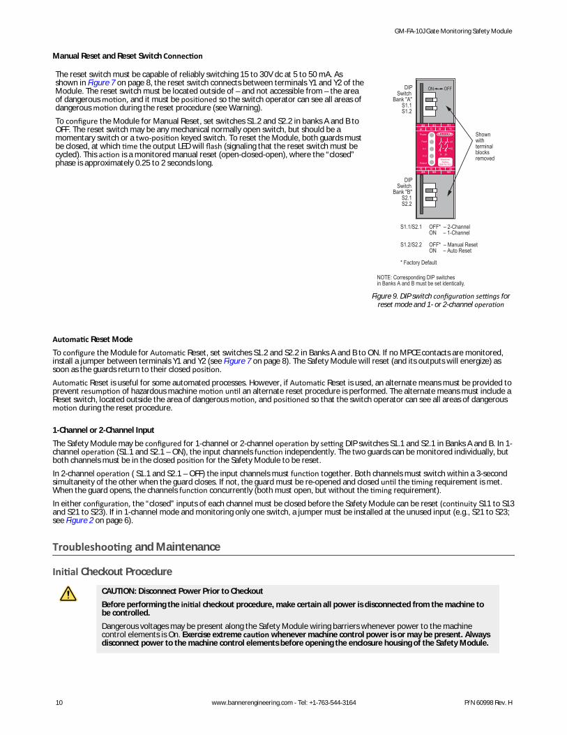
LEDsFault, Probably Cause, and Procedures
Power Fault Input 1 Input 2 Output
On On Flashing On or Off Off INPUT CHANNEL 1 FAULT (S11/S12/S13)a. S13 Open (guard closed)b. S12 Open (guard open)c. S11 Open (guard is open or closed)d. Short between S11 and S12
On On On or Off Flashing Off INPUT CHANNEL 2 FAULT (S21/S22/S23)a. S23 Open (guard closed)b. S22 Open (guard open)c. S21 Open (guard is open or closed)d. Short between S21 and S22
On On Flashing Flashing Off SHORT BETWEEN INPUT CHANNELSa. Short between S11 and S21
On On On or Off On or Off Off SIMULTANEITY FAULTa. 2-channel simultaneity > 3 seconds (configured for 2-channeloperation)b. Channel simultaneity > 1 second (NO/NC did not switch within 1second)
See Configuration on page 3 for description of complementary switching and2-channel operation.
Flashing Flashing Off Off Off DIP-SWITCH ERRORa. DIP-switch settings are incorrect; Bank A does not match Bank B
See Configuration on page 9 for DIP-switch configuration.
On On On On Flashing OPEN RESET FAULTa. Y1/Y2 open when configured for Auto Reset
See Configuration on page 9 for Manual/Auto Reset information.
On Flashing Off Off Off INTERNAL FAULT (See Repairs on page 12)a. Incorrect check sumb. Internal relay failure (e.g., welded contact due to inductive loadarcing.)c. Low input powerd. Other internal fault
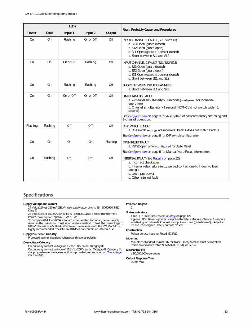
SpecificationsSupply Voltage and Current
24 V dc ±15% at 150 mA (SELV-rated supply according to EN IEC 60950, NECClass 2)24 V ac ±15% at 150 mA, 50-60 Hz +/- 5% (NEC Class 2-rated transformer)Power consumption: approx. 3 VA / 3 WTo comply with UL and CSA standards, the isolated secondary power supplycircuit in the installation must incorporate a method to limit the overvoltage to0.8 kV. The use of a 500 mA, slow blow fuse in series with the +24 V ac/dc ishighly recommended. The GM-FA-10J does not contain an internal fuse.
Supply Protection CircuitryProtected against transient voltages and reverse polarity
Overvoltage CategoryOutput relay contact voltage of 1 V to 150 V ac/dc: Category IIIOutput relay contact voltage of 151 V to 250 V ac/dc: Category II (Category III,if appropriate overvoltage reduction is provided, as described on OvervoltageCat II and III)
Pollution Degree2
Status Indicators1 red LED: Fault (see Troubleshooting on page 12)4 green LEDs: Power – power is supplied to Safety Module; Channel 1 – inputssatisfied (guard closed); Channel 2 – inputs satisfied (guard closed); Output –K1 and K2 energized, safety outputs closed
ConstructionPolycarbonate housing. Rated IEC IP20
MountingMounts to standard 35 mm DIN rail track. Safety Module must be installedinside an enclosure rated NEMA 3 (IEC IP54), or better.
Mechanical life≥ 50,000,000 operations
Output Response Time35 ms max.
GM-FA-10J Gate Monitoring Safety Module
P/N 60998 Rev. H www.bannerengineering.com - Tel: +1-763-544-3164 13
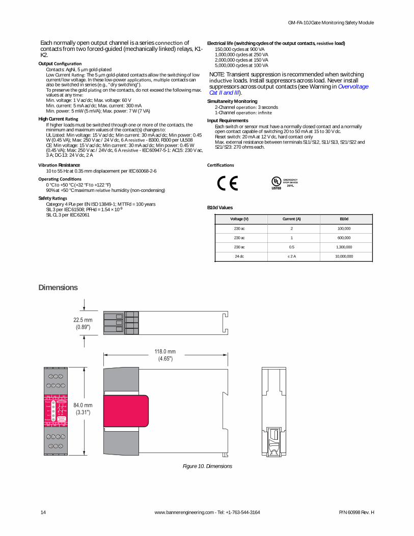
Each normally open output channel is a series connection ofcontacts from two forced-guided (mechanically linked) relays, K1-K2.
Output ConfigurationContacts: AgNi, 5 μm gold-platedLow Current Rating: The 5 μm gold-plated contacts allow the switching of lowcurrent/low voltage. In these low-power applications, multiple contacts canalso be switched in series (e.g., “dry switching”).To preserve the gold plating on the contacts, do not exceed the following max.values at any time:Min. voltage: 1 V ac/dc; Max. voltage: 60 VMin. current: 5 mA ac/dc; Max. current: 300 mAMin. power: 5 mW (5 mVA); Max. power: 7 W (7 VA)
High Current RatingIf higher loads must be switched through one or more of the contacts, theminimum and maximum values of the contact(s) changes to:UL Listed: Min voltage: 15 V ac/dc; Min current: 30 mA ac/dc; Min power: 0.45W (0.45 VA); Max: 250 V ac / 24 V dc, 6 A resistive - B300, R300 per UL508CE: Min voltage: 15 V ac/dc; Min current: 30 mA ac/dc; Min power: 0.45 W(0.45 VA); Max: 250 V ac / 24V dc, 6 A resistive - IEC 60947-5-1: AC15: 230 V ac,3 A; DC-13: 24 V dc, 2 A
Electrical life (switching cycles of the output contacts, resistive load)150,000 cycles at 900 VA1,000,000 cycles at 250 VA2,000,000 cycles at 150 VA5,000,000 cycles at 100 VA
NOTE: Transient suppression is recommended when switchinginductive loads. Install suppressors across load. Never installsuppressors across output contacts (see Warning in OvervoltageCat II and III).
Input RequirementsEach switch or sensor must have a normally closed contact and a normallyopen contact capable of switching 20 to 50 mA at 15 to 30 V dc.Reset switch: 20 mA at 12 V dc, hard contact onlyMax. external resistance between terminals S11/S12, S11/S13, S21/S22 andS21/S23: 270 ohms each.
Vibration Resistance10 to 55 Hz at 0.35 mm displacement per IEC 60068-2-6
Operating Conditions0 °C to +50 °C (+32 °F to +122 °F)90% at +50 °C maximum relative humidity (non-condensing)
Safety RatingsCategory 4 PLe per EN ISO 13849-1; MTTFd = 100 yearsSIL 3 per IEC 61508; PFHd = 1.54 × 10⁻⁹
SIL CL 3 per IEC 62061
Certifications
B10d Values
Voltage (V) Current (A) B10d
230 ac 2 100,000
230 ac 1 600,000
230 ac 0.5 1,300,000
24 dc ≤ 2 A 10,000,000
Dimensions
S12A1
S11 S13
S23 S21 S22
13 23 Y1
Y2 14 24 A2
K1
K2
14 24
MachineSafety
GM-FA-10I
Power
Fault
In 1
In 2
Output
118.0 mm(4.65")
84.0 mm(3.31")
22.5 mm(0.89")
Figure 10. Dimensions
GM-FA-10J Gate Monitoring Safety Module
14 www.bannerengineering.com - Tel: +1-763-544-3164 P/N 60998 Rev. H
Three pole-stable reed switchesRepeat Switching Accuracy
±0.1 mm (±0.004 inches)Construction
Epoxy-encapsulated circuit in polyamide housingEnvironmental Rating
NEMA 4X, IEC IP67Switching Capacity
30V dc max @ 0.25W (27 Ω fuse resistor in-line, each channel)Operating Temperature
–5° to +70°C (+23° to +158°F)
ConnectionsIntegral PVC-jacketed 3 m (10 ft) 4-wire cable.Cable O.D. is 5 mm (0.2 inches).Wires are 24 AWG (0.25 mm²).
HardwareAll mounting hardware is supplied by user. Use of permanent fasteners orlocking hardware is recommended to prevent loosening or displacement of theactuator and switch body. Mounting holes in the magnet and sensor accept M4(#6) hardware (see Magnetic Switch Dimensions on page 16).
Application NoteThe sensor/magnet pair must be mounted a minimum distance of 15 mm (0.6inches) from any magnetized or ferrous materials. Multiple SFA-IMB1 (usedwith SI-MAG1xx) and SFA-IMB2 (used with SI-MAG2xx) can be used as spacers.
2 To order 9 m (30 ft) cable models, add “w/30” to the model number (e.g., SI-MAG1SM w/30).3 Cable opposite see Figure 13 on page 16)4 90° orientation (see Direction of Approach for SI-MAG1xx Sensor/Magnet Pairs on page 17)
GM-FA-10J Gate Monitoring Safety Module
P/N 60998 Rev. H www.bannerengineering.com - Tel: +1-763-544-3164 15
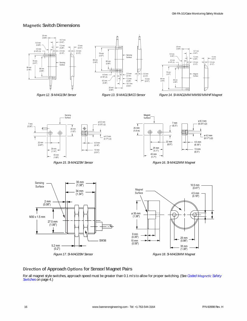
Magnetic Switch Dimensions
88 mm(3.46")
78 mm(3.07")
68 mm(2.68")
4.5 mm(0.18") (3)
6.5 mm(0.26")
25 mm(0.98")
10.7 mm(0.42")
7.2 mm(0.28")2.5 mm(0.10")
13 mm(0.51")
SensingSurface
3.0 mm(0.12")
Figure 12. SI-MAG1SM Sensor
88 mm(3.46")
78 mm(3.07")
68 mm(2.68")
4.5 mm(0.18") (3)
6.5 mm(0.26")
25 mm(0.98")
10.7 mm(0.42")
7.2 mm(0.28")
2.5 mm(0.10")
13 mm(0.51")
SensingSurface
3.0 mm(0.12")
Figure 13. SI-MAG1SMCO Sensor
88 mm(3.46")
78 mm(3.07")
68 mm(2.68")
4.5 mm(0.18") (3)
6.5 mm(0.26")
25 mm(0.98")
10.7 mm(0.42")
7.2 mm(0.28")
2.5 mm(0.10")
13 mm(0.51")
MagnetSurface
3.0 mm(0.12")
Figure 14. SI-MAG1MM/MM90/MMHF Magnet
43 mm(1.69")
22 mm(0.87")
7 mm(0.28")
26 mm(1.02")
ø 8.3 mm(0.33") (2)
ø 4.3 mm(0.17") (2)
SensingSurface
29 mm(1.14") 13 mm
(0.51")
4.5 mm(0.18")
Figure 15. SI-MAG2SM Sensor
43 mm(1.7")
22 mm(0.9")
7 mm(0.3")
26 mm(1.0 in)
ø 8.3 mm(0.33") (2)
ø 4.3 mm(0.17") (2)
MagnetSurface
29 mm(1.1")
13 mm(0.5")
4.5 mm(0.18")
Figure 16. SI-MAG2MM Magnet
35 mm(1.38")
34 mm(1.34")
2 mm(0.08")
SW365.2 mm
(0.2")
27.5 mm (1.06")
M30 x 1.5 mm
SensingSurface
Figure 17. SI-MAG3SM Sensor
ø 35 mm (1.38")
15 mm (0.59")
9 mm (0.35")
35 mm(1.38")
25 mm(0.98")
4.5 mm (0.18")
10.5 mm(0.41")Magnet
Surface
Figure 18. SI-MAG3MM Magnet
Direction of Approach Options for Sensor/Magnet PairsFor all magnet style switches, approach speed must be greater than 0.1 m/s to allow for proper switching. (See Coded Magnetic SafetySwitches on page 4.)
GM-FA-10J Gate Monitoring Safety Module
16 www.bannerengineering.com - Tel: +1-763-544-3164 P/N 60998 Rev. H
Direction of Approach for SI-MAG1xx Sensor/Magnet Pairs
Sensing face
CodedMagnetDirection of
Movement
Magnet Sensor
Normal Direction of Approach: movement is perpendicular to theplane of the sensing face
Direction ofMovement
Incorrect Direction of Approach: Label to label approach of sensorand magnet is not possible
Direction ofMovement
CodedMagnet
MagnetSensor
Alternate Direction of Approach: movement is parallel to theplane of the sensing face
Direction ofMovement
Incorrect Direction of Approach: 90º approach of sensor andmagnet is only possible with the SI-MAG1MM90 magnet
GM-FA-10J Gate Monitoring Safety Module
P/N 60998 Rev. H www.bannerengineering.com - Tel: +1-763-544-3164 17
Direction of Approach for SI-MAG2xx Sensor/Magnet Pairs
Direction ofMovement
CodedMagnet
MagnetSensor
Normal Direction of Approach: movement is perpendicular to theplane of the sensing face
Direction ofMovement
Incorrect Direction of Approach: Label to label approach of sensorand magnet is not possible
Direction ofMovement
Alternate Direction of Approach: movement is parallel to theplane of the sensing face
Direction ofMovement
Incorrect Direction of Approach: 90º approach of sensor andmagnet is not possible
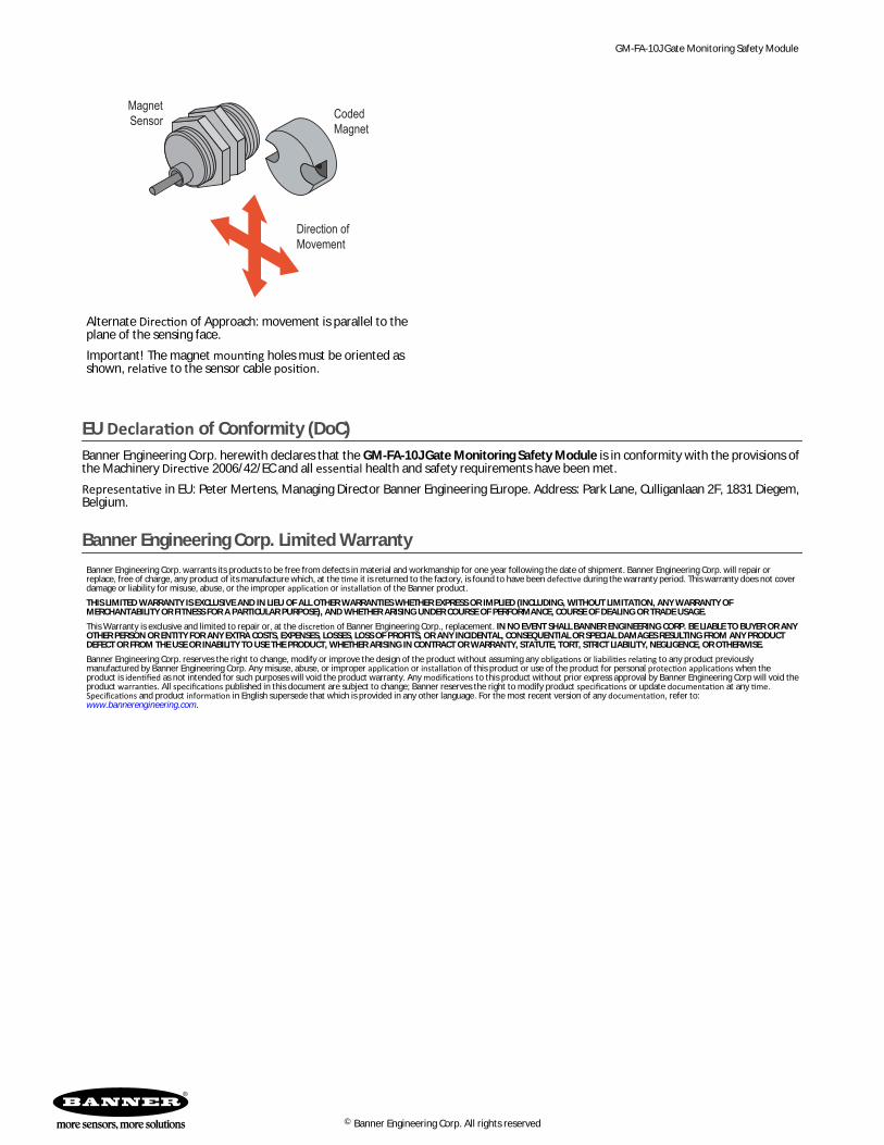
Direction of Approach for SI-MAG3xx Sensor/Magnet Pairs
Direction ofMovement
CodedMagnetMagnet
Sensor
Normal Direction of Approach: movement is perpendicular to theplane of the sensing face.Important! The magnet mounting holes must be oriented asshown, relative to the sensor cable position.
Direction ofMovement
CodedMagnet
MagnetSensor
Incorrect Magnet Orientation
GM-FA-10J Gate Monitoring Safety Module
18 www.bannerengineering.com - Tel: +1-763-544-3164 P/N 60998 Rev. H
Direction ofMovement
CodedMagnet
MagnetSensor
Alternate Direction of Approach: movement is parallel to theplane of the sensing face.Important! The magnet mounting holes must be oriented asshown, relative to the sensor cable position.
EU Declaration of Conformity (DoC)Banner Engineering Corp. herewith declares that the GM-FA-10J Gate Monitoring Safety Module is in conformity with the provisions ofthe Machinery Directive 2006/42/EC and all essential health and safety requirements have been met.Representative in EU: Peter Mertens, Managing Director Banner Engineering Europe. Address: Park Lane, Culliganlaan 2F, 1831 Diegem,Belgium.
Banner Engineering Corp. Limited WarrantyBanner Engineering Corp. warrants its products to be free from defects in material and workmanship for one year following the date of shipment. Banner Engineering Corp. will repair orreplace, free of charge, any product of its manufacture which, at the time it is returned to the factory, is found to have been defective during the warranty period. This warranty does not coverdamage or liability for misuse, abuse, or the improper application or installation of the Banner product.THIS LIMITED WARRANTY IS EXCLUSIVE AND IN LIEU OF ALL OTHER WARRANTIES WHETHER EXPRESS OR IMPLIED (INCLUDING, WITHOUT LIMITATION, ANY WARRANTY OFMERCHANTABILITY OR FITNESS FOR A PARTICULAR PURPOSE), AND WHETHER ARISING UNDER COURSE OF PERFORMANCE, COURSE OF DEALING OR TRADE USAGE.This Warranty is exclusive and limited to repair or, at the discretion of Banner Engineering Corp., replacement. IN NO EVENT SHALL BANNER ENGINEERING CORP. BE LIABLE TO BUYER OR ANYOTHER PERSON OR ENTITY FOR ANY EXTRA COSTS, EXPENSES, LOSSES, LOSS OF PROFITS, OR ANY INCIDENTAL, CONSEQUENTIAL OR SPECIAL DAMAGES RESULTING FROM ANY PRODUCTDEFECT OR FROM THE USE OR INABILITY TO USE THE PRODUCT, WHETHER ARISING IN CONTRACT OR WARRANTY, STATUTE, TORT, STRICT LIABILITY, NEGLIGENCE, OR OTHERWISE.Banner Engineering Corp. reserves the right to change, modify or improve the design of the product without assuming any obligations or liabilities relating to any product previouslymanufactured by Banner Engineering Corp. Any misuse, abuse, or improper application or installation of this product or use of the product for personal protection applications when theproduct is identified as not intended for such purposes will void the product warranty. Any modifications to this product without prior express approval by Banner Engineering Corp will void theproduct warranties. All specifications published in this document are subject to change; Banner reserves the right to modify product specifications or update documentation at any time.Specifications and product information in English supersede that which is provided in any other language. For the most recent version of any documentation, refer to: www.bannerengineering.com.