96
GM9907 -L2 user's manual GM9907-L 2 01902 0 0 V0 2 .00.00

GM9907 -L2
user's manual
GM9 9 07 -L 2 0 19 02 0 0
V 0 2 . 00 .0 0

© 2018, Shenzhen Jieman Technology Co., Ltd., all rights reserved.
No unit or individual may copy, distribute, transcribe or translate into other language
versions in any form or by any means without the permission of Shenzhen Jieman
Technology Co., Ltd.
As our products have been continuously improved and updated, our company reserves the
right to modify this manual at any time without prior notice . To do this, please visit the
company website frequently to get timely information.
Company website http://www.szgmt.com
Implementation standards of this product : GB/T 7724—2008
Overview
The GM9907 Packaging Controller is a new weighing control instrument specially developed for the single
scale incremental method automatic quantitative packing scale. The controller English display interface for
easy operation; completely new algorithm faster and more accurate control so that the load; the USB port
and dual port serial device to make it easier to system interconnect. Can be widely used in feed, chemical,
food and other industries that require quantitative packaging equipment.
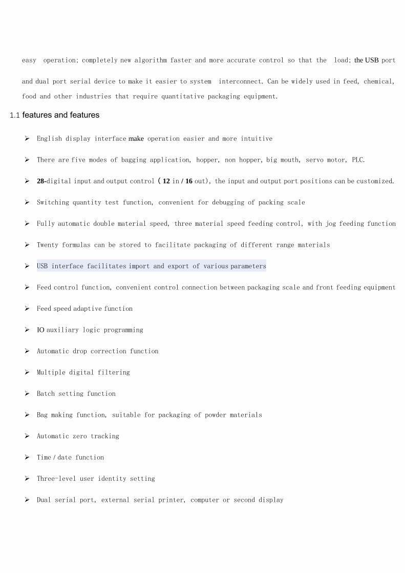
1.1 features and features
English display interface make operation easier and more intuitive
There are five modes of bagging application, hopper, non hopper, big mouth, servo motor, PLC.
28-digital input and output control ( 12 in / 16 out), the input and output port positions can be customized.
Switching quantity test function, convenient for debugging of packing scale
Fully automatic double material speed, three material speed feeding control, with jog feeding function
Twenty formulas can be stored to facilitate packaging of different range materials
USB interface facilitates import and export of various parameters
Feed control function, convenient control connection between packaging scale and front feeding equipment
Feed speed adaptive function
IO auxiliary logic programming
Automatic drop correction function
Multiple digital filtering
Batch setting function
Bag making function, suitable for packaging of powder materials
Automatic zero tracking
Time / date function
Three-level user identity setting
Dual serial port, external serial printer, computer or second display

With network port communication function , it is convenient to communicate with the host computer
1.2 front panel description
Interface 1 description :
User information, weight status area , alarm prompt bar and function parameter area are retained . Increase the
parameter display area and shortcut keys for easy setting
1 : Parameter display area : Display the relevant parameters of the current recipe.
2: Shortcuts: increased 8 customizable shortcuts, setting.
1.3 rear panel description

1.4 Technical Specifications
1.4. 1 General Specifications
Power source: DC24V
Power filter: included
O p e r a t i n g temperature: -10 ~ 40 ℃
M a x i m u m humidity: 90% RH non-condensing
Power consumption : about 15 W
P h y s i c a l d i m e n s i o n s : 190 mm × 124 mm × 48 mm
1.4 .2 analog part
Sensor p o w e r s o u r c e : DC 5 V 125 mA (MAX )
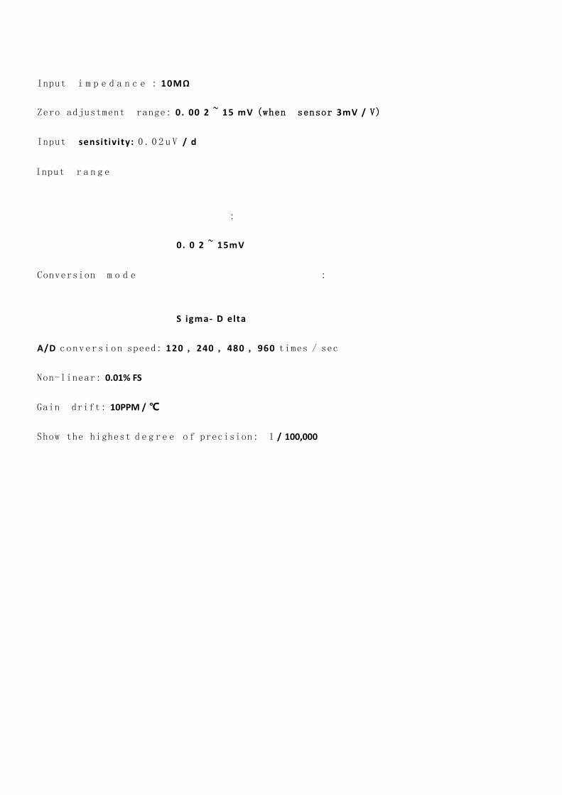
Input i m p e d a n c e : 10MΩ
Zero adjustment range: 0. 00 2 ~ 15 mV (when sensor 3mV / V)
Input sensit ivity: 0 . 0 2 u V / d
Input r a n g e
:
0. 0 2 ~ 15mV
Conversion m o d e :
S igma- D elta
A/D conversion speed: 120 , 240 , 480 , 960 times / sec
Non-linear: 0.01% FS
Gain drift: 10PPM / ℃
Show the highest d e g r e e o f precision: 1 / 100,000

1.4 .3 digital part
Display: 7 inch resistive touch screen
Negative N u m b e r Display: "-"
Overload Display: Chinese "overrange wt / sensor signal is too small."
Decimal point position: 5 optional

2.installation
2.1 General principles
1 ) Open the hole in the appropriate position of the control cabinet (opening size 179 ( ± 1 ) mm
× 113 ( ± 1 ) mm )
2 ) Load the meter into the control cabinet.
3 ) Remove the side strips from the accessories, fix them on both sides of the meter, and fix them with M3*10 screws.
2.2 Sensor connection
The GM9907 package controller can be connected to a resistive strain bridge sensor. When using a six-wire sensor,
the sensor's SN+ and EX+ must be shorted , and SN- and EX- should be shorted .
EX+ : Power supply is positive EX- : Power negative SN+ : Sensing positive SN- : Inductive negative SIG+ : Positive
signal SIG- : negative signal
2.3 switch interface connection
GM 9907 package controller 28 comprises a switch input, output control (the 12/16). The photoelectric
isolation mode is adopted, and the internal power supply of the instrument is driven. Meter switch input is active

low; output open-collector transistor output taken, each line of the drive current up to 5 00m A, the maximum
full load current of 3A. The terminal wiring is as shown below:
Switch input interface diagram
Switch output interface diagram
GM 9907 packaging controller to switch the user can customize the way, to facilitate the user lines and
some special applications, digital content See Section 3.7.

2.4 power connection
The GM9907 package controller uses a 24V DC power supply. The connection is as shown below:
2.5 serial port connection
The GM9907 provides two serial communication interfaces as shown in the figure below. The serial port one
is RS - 232 mode (terminal port TX D , RX D , GND ); the serial port 2 is RS - 485 , (terminal
port A , B , GND ). Serial port support: MODBUS protocol, continuous mode and print format .
Instrument and computer connection diagram

Instrument and computer connection diagram ( RS-232 mode)
Instrument and host computer connection diagram ( RS-485 mode)
2.6 touch screen calibration
The touch screen needs to be calibrated when the new product is used for the first time or after a long time.
The touch screen calibration method:
Power on the GM9907 , and press and hold the touch screen at any time . The system switches to the touch screen
calibration interface. Press and hold the cursor position on the screen to complete the calibration. After the
coordinates of the point are displayed, the screen will automatically enter the next calibration point. Follow
the change of the cursor position and press and hold, the calibration is completed, and the interface displays

the coordinates of the five calibration points, and then automatically enters the main interface of the product. If
you enter the touch screen calibration interface by mistake, you can exit the interface by pressing the “Cancel”
button in the lower right corner.

3 menu
Click the system menu to enter the parameter menu and query and modify each parameter.
The system menu interface is as shown in the figure above. The left side is the parameter item list, and the right side is the parameter
item brief description and some parameter item information.
Click the sub-option button to enter the current parameter item to view and set the attribution parameter information.
Press [Back] to exit the current interface and return to the previous interface.
menu Parameter
item parameter list Parameter Description
system
System
dish
single
Recipe
parameters
0: Quantitative value Set the package weight value related
parameters
1 : time parameter Set the delay time related parameters of
the feeding process
2 : Super poor
parameter
Set parameters such as excess weight,
mode, and feeding
3: Drop correction
parameter
Set the difference correction method,
correction range and other related
parameters
4: Slow plus jog
parameters
Set slow plus jog switch, time and other
related parameters
5: There are bucket
scale parameters
Set the relevant parameters of the bucket
scale structure
6: No hopper scale
parameters
Set the relevant parameters of the hopper
less scale structure

7: PLC parameters Set the state of the PLC parameters
8: ton package scale
parameters
Set the relevant parameters of the ton
package scale structure
9: Valve port scale
parameters
Set the relevant parameters of the valve
port scale structure
System and
communication
0: weight parameter Set the judgment, clear , and other
weightparameters
1: Filter parameters Set filter switch, filter level
2: Function
parameters
Set parameters such asadaptive and fixed
value
3: scale body
structure
Select the scale body structure ,
feedingmethod, etc.
4: Serial port(232) Set serial port (RS 232 )related parameters
5: Serial port (485 ) Set serial port (RS485)related parameters
6: Network port Set network port related parameters
Peripheral
parameters
0: bag parameters Set the number of shots, the number of
times and other parameters
1: coding parameters Set the relevant parameters of the coding
mechanism
2: Conveyor
parameters
Set the relevant parameters of the
conveyor
3: Print parameters Set parameters for automatic printing
function
4 : sewing machine
parameters
Set sewing machine, thread cutting
machine and other related parameters
5: Unloading rapping
parameters
Set parameters such as discharge
rapping time and number of times
6: Adding and
discharging timeout
judgment
Set the parameters related to the loading
and unloading timeout
7: Auxiliary pulse
parameters
Set the relevant parameters of the
auxiliary pulse
Motor
parameters
0: Motor parameters Set recipe number, motor group number
1; feeding parameters Set feed related parameters
2: Clip loose bag
parameters
Set the relevant parameters of the clip
loose bag
3: Discharge
parameters Set discharge related parameters
School scale 0: weighing
parameter
Set parameters such as unit, decimal
point, range, etc.

1: weight calibration
scale
Performs calibration
operation for calibrating the meter weight
value
Cumulative
and batch
0: total
accumulation and
batch
View, clear, print the total
cumulative information
1: Formula
accumulation ( 1 -10 )
View, clear, print recipe( 1-10 ) package
accumulation information
2: Formula
accumulation ( 11-20)
View, clear, print recipe( 1 1 - 20) package
accumulation information
3: User accumulation View cumulative
parameters for different users
Switch
0: Digital input
definition
Define the meaning of the meter input
port
1 : Switch output
definition
Define the meaning of the meter output
port
2: Switch input test Test whether the connection of each input
port is normal.
3 : Switch output test Test whether each output port is
connected properly.
Auxiliary logic
parameter
0: Auxiliary logic-1 Auxiliary logic 1function customization
1: auxiliary logic-2 Auxiliary logic 2 function customization
2: Auxiliary Logic-3 Auxiliary logic 3 function customization
3: Auxiliary Logic-4 Auxiliary logic 4 function customization
4: Auxiliary Logic- 5 Auxiliary logic 5 function customization
5: Auxiliary Logic- 6 Auxiliary logic 6 function customization
User
Management
0: User login View or switch users
1: User editing Edit user permissions, passwords, etc.
2: Automatic login Set up automatic login users
system
message
0: Version
information
View software version and set system
time
1: password
management
Password management of various
parameters (calibration, cumulative clear
password switch must be on)
2: reset / backup Restore various parameters to factory
settings and data backup
3: USB data export
Out operation from the
instrument guide,formulation, peripherals,
motor, calibration,switch parameter, the
serial port parameters

4: USB data import
Import work, recipes,peripherals,
motors,calibration , switch parameters,
serial parameters to the meter
5: Short cut definition Define debug interface shortcuts
6: Other settings Select language, adjust screen brightness,
set screen saver
3.1 formulation parameters
Recipe
parameter
item
parameter Description
Quantitative
value
Used to set the package weight value related parameters
1 Recipe Select the recipe number . Initial value: 1 ; Range: 1~20 .

number
2. Target
value Quantify the target value.
3. quickly
increasethe
amount of
advance
In the quantification process, if the weighing value ≥ the
target value - fast increase the advance amount, the quick
addition is turned off .
3. before
touching
the amount
In the process of quantification, if the weighing value ≥ the
target value - the medium plus the advance amount, the
middle plus is turned off.
5. drop
value
In the quantification process, if the weighing value ≥ the
target value - the falling value, the slow addition is turned off.
6. zero zone
value
During the quantification process, if the weighing value is ≤
zero zone value, the discharge delay timer is started.
Time
parameter
Used to set the delay time related parameters of the feeding process
1 beforethe
addition
Delay
In the metering bucket mode, when the quantitative process
starts, after the delay time, the meter will judge and stabilize
(if it does not meet the clear interval condition, it will not
judge and not clear), and then start the feeding process;
In the no-measure bucket mode, after the pocket is
completed, after the delay time, the meter is judged to be
stable and peeled.Initial value: 0.5 ; Range: 0.0~99.9 . (Unit: s )
2. The quick
feed ban
sentenced
to time
At the beginning of the quantification, during this time, in
order to avoid overshoot, no weight judgment is made, and
the quick addition is always effective.Initial value: 0.9 ;
Range: 0.0~99.9 . (Unit: s )
3. Canada
banned
sentenced
to time
After the end of quick feed, in this casebetween, in order to
avoid overshooting the weight determination is not
performed, has been effectively added. Initial value: 0.9 ;
Range: 0.0~99.9 . (Unit: s )
4. slow feed
ban
sentenced
to time
After added, this time in between, in order to avoid
overshooting the weight determination is not performed, the
slow feed has been effective. Initial value: 0.9 ;
Range: 0.0~99.9 . (Unit: s )
5. Setpoint
hold time
When the setting method is selected as “delay setting”, after
the slow feeding is turned off (or the super-defect difference
is turned on, the super-defect alarm is finished), the setting
value is started, and the holding time is passed, and the fixed
value is considered to be finished, and the next process is
entered. .
Initial value: 0.5 ; Range: 0.0~ 99.9 . (Unit: s)
6. After a After the bag signal is given, after the delay, the meter judges

delayfolder
bag
that the bagging operation is completed.
Initial value: 0.5 ; Range: 0.0~99.9 . (Unit: s )
7. Pine bags
before
delay
After the bucket mode discharge is completed, the loose bag
signal is output after the delay time;
After the no-bucket mode setting (beat bag) is completed, the
loose bag signal is output through this delay.
Initial value: 0.5 ; Range: 0.0~99.9 . (Unit: s )
8.Discharge
Delay
During the unloading process, when the weight value of the
weighing bucket is less than the zero zone value, the delay is
started, and the time delay is closed to close the discharging
signal.
Initial value: 0.5 ; Range: 0.0~99.9 . (Unit: s )
Super
poorparameter
Used to set parameters related to excess weight, mode,feeding, etc.
1 under super heterodynedetection
switch
“ On / Off ” is optional. When this
parameter is set to “ On ” , the
quantitative process judges the excess
error.
2. Super owe differencepause switch
“On / Off” is optional. When it is set to
“On”, when the quantitative process is
over or under, the instrument pauses and
waits for the user to process .
The digital input is stopped urgently,
returns to the stop state, and the alarm is
cleared; or the digital input clear alarm
can clear the alarm and continue the
quantitative process.
3. Excess Under the alarm
timedifference
Without manually clear the alarm, the
alarmtime difference over under its
own alarm off.
Initial
value: 1.0; range: 0.0 to 9. 9.9. (units )
4 ultradifference
In the process of quantification, if the
weighing value ≥ the target value + the
excess value, it is judged to be excessive.
Initial value: 0 .
5. owe the difference
In the process of quantification, if the
weighing value ≤ target value -
under-difference, it is judged as poor.
Initial value: 0 .
6. Fed under differentialswitch
Set the underfeed correction judgment
switch.
On: Slowly add the feed according to the

number of feeds. Off: Do not replenish
when there is a shortfall.
7. Themaximum number of times due
to poor feeding
When the quantitative process is judged
to be inferior, the feed is slowly added
according to this value.
Initial value: 1 ; range 1~99 .
8. Lesseffectivefeeding timedifference
When feeding the output, the effective
time is added slowly during an on-off
cycle .
Initial
value : 0.5 ; range: 0.0 to 9 9 .9 . (units )
9. invaliddue to poor feeding time
When feeding an output, a pass off the
cycletime has no effect on chronic.
Initial
value : 0.5 ; range: 0.0 to 9 9 .9 . (units )
Drop correction
parameter
Used to set relevant parameters for automatic adjustment ofdrop difference
1. Fall correction switch
The drop value is the weight value that
has not fallen into the measuring hopper
after the slow plus signal is turned off. The
drop correction is corrected according to
the actual blanking value as required.
(Note: If the drop correction and adaptive
functions are turned on at the same time,
the drop correction function is invalid)
2. fallcorrection sampling times
The meter averages the difference of the
set number of times as the basis for the
drop correction.
Initial value: 1 ; Range: 1 to 99 .
3. fallcorrection range
When the current drop value exceeds the
set range, the drop will not be counted in
the arithmetic mean range.
Initial value: 2 .0 ; Range: 0.0 to 9.9 ( % of
target value ) .
4. fall correction magnitude
The magnitude of each drop correction.
Three ranges are available in 100% , 50% ,
and25% .
Initial value: 50 % .
Slow plus jog
parameters
Used to set manual slow feeding related parameters
1. Slow addswitch
“On / Off” is optional. When set to
“On”, the meter is slowly added and
jogged.
Initial value: off.

2. Inching slowly addeffective time
When the jog output is slowly added, the
effective time is added slowly during an
on-off cycle .
Initial
value : 0.5 ; range: 0.0 to 9.9 . (unit s)
3. Slow plusjogging inactive time
When the jog output is slowly added, the
inactive period is slowly added during an
on-off period .
Initial
value : 0.5 ; range: 0.0 to 9.9 . (unit s)
Bucket
scaleparameter
Used to set the relevant parameters of the bucket scale mode
1. Single scalecombination number
When there is a bucket scale structure ,
theloose bag is unloaded several times. If
it is0 , the meter discharges directly after
the feeding is completed without judging
whether the pocket is valid.
Initial value : 1 ; Range: 0 to 99 .
No bucket
scaleparameters
Used to set parameters related to the bucketless scale mode
1. Re-pocketdelay start time
Effective interlocking mode without
fighting,A scale B when the front end of
the conveyorscale after the rear end of
the conveyor, andthe double scale bulk
bags is not the samemodel
as loose bags. If the addition is complete
loose bags B scale, the scale is not loose
bags A, B scale case again a bag
clip, towait after the completion of the
addition Aloose scale bags, and after
starting the
conveyor, after which time delay before
scale BStart feeding.
Initial
value: 4.0 ; range: 0.0 to 99.9 . (unit s)
(Note: This parameter is only valid when
the bag is not at the same time.)
PLC parameters
Used to set PLC mode related parameters
1. PLC- ultra difference
When the weighing value > target value +
excess value, the out-of-tolerance output
is valid
Initial value: 0.00 ; range: 0.00~100.00 .
2. PLC- owe the difference When the weighing value <target value -
under-difference, the under-output is

valid
Initial value: 0.00 ; range: 0.00~100.00 .
3. The upper limit PLC-
When the weighing value > upper limit
value, the upper limit output is valid
Initial value: 0.00 ; range: 0.00~100.00 .
4. PLC- lower limit
When the weighing value is < lower limit,
the lower limit output is valid.
Initial value: 0.00 ; range: 0.00~100.00 .
Tons of packing
scaleparameters
Used to set the relevant parameters of the ton package scale mode
1. Delaytimepunching bags
The bag delay time until the bag is
completed .
Initial
value : 0.5 ; range: 0.0 to 9.9 . (unit s)
2 bracketautomatic upswitch
After the hanging bag is finished, it is
judged whether the bracket automatic
rising switch is turned on, and waits for
the manual rising bracket signal when it is
not opened .
3. The stent uplink delay time
This delay is executed after the rising
signal is sent.
Initial value: 5.0; range: 0.0 to 9.9. (unit s )
4. bracket downlinkdelay time
This delay is initiated after the
quantitative delay has expired.
Initial value: 5.0; range: 0.0 to 9.9. (unit s )
5 bracket up timeout(parameter
retained)
The maximum waiting time for the
metering bracket to be in position .
Initial value: 5.0; range: 0.0 to 9.9. (unit s )
6. The stentdownlink
timeout(parameter retained)
The maximum waiting time for the
metering bracket to go down .
Initial value: 5.0; range: 0.0 to 9.9. (unit s )
7. blowingtime
Blower blow output time .
Initial
value : 0.5 ; range: 0.0 to 9.9 . (unit s)
8. A beltrunning time(this parameter
retained)
Electric mode, when the belt A stop signal
is invalid, and the loose bags, the belt
running time after punching
bag A runningoperation has
been completed, the running time after
starting the belt B.
Initial value: 5.0; range: 0.0 to 9.9. (unit s )
9. Belt BRuntime(this parameter
retained)
In the electric mode , when the stop signal
of the belt B is invalid, the belt B stops

running after the belt running time .
Initial value: 5.0; range: 0.0 to 9.9. (unit s )
Valve port
scaleparameter
Used to set the valve scale mode related parameters
1. The time delay before the bag
The delay time before the bag is started at
the same time when the loose bag starts
to start .
Initial
value : 0.5 ; range: 0.0 to 9.9 . (unit s)
2. bag effectivetime
The time is started after the delay
timebefore the bag is lifted , and the bag
signal output is valid. After the time is
over, the bag signal output is invalid.
Initial
value : 0.5 ; range: 0.0 to 9.9 . (unit s)
3. Push bagsDelay Time
When the loose bag start delay starts, the
delay time before pushing the bag is
started at the same time.
Initial
value : 0.5 ; range: 0.0 to 9.9 . (unit s)
4. Push the bag effective time
The time is started after the delay
timebefore pushing the bag , and the push
bag signal output is valid. After the time is
over, the push bag signal output is invalid .
Initial
value : 0.5 ; range: 0.0 to 9.9 . (unit s)
3.2 system and communication parameters
Under the system and communication parameters interface:
Click the sub-option button to enter the corresponding parameter item to view and set the attribution parameter
information.
Press [Back] to exit the current interface and return to the previous interface.
System
andcommunicationparameters parameter Description
Weightparameter
1. Criteria of Stability
range
During the judgment time, the weight change
range is within this set value and the meter
judges that the scale is stable.
Initial value: 2 ; Range: 0 to 99 (d) .
2. Criteria of Stability
time First value: 0.3; range: 0.1 to 99.
3. Clear range The range can be cleared .
Initial value: 50 ; Range: 1 to 99 ( % of full

scale) .
3. Zero trackingrange
The weight value is within this range and the
meter is automatically cleared.When it is 0 ,
zero tracking is not performed.
Initial value: 0 ; range: 0 to 9 (d) .
5. Zero TimeTracking First Value: 20; range: 0.1-9 9.9. (unit s)
6. A / Dsampling rate
A/D sampling rate.
120 times / sec, 240 times / sec, 480times /
sec, 960 times / sec.
Initial value: 480 times / sec.
Filteringparameter
1 . Stop filteringlevel Filter strength rating in the stopped state.
Initial value : 7 ; range 0 ~ 9 .
2. Secondary
filter switch
On/off optional, secondary filtering based on
digital filtering.
Initial value: off.
3. Dynamic filter switch
During the packaging process, whether to
perform the filter operation switch and set
“On”, the following three parameters are
valid.
4. Filter feed grade
Filter parameters during feeding: 9 : The
filtering effect is the strongest.
Initial value: 2 ; Range: 0 to 9 .
5 level filter setting
Filter parameters during the setting
process: 9 : The filtering effect is the strongest.
Initial value: 7 ; Range: 0 to 9 .
6. Unloading smoothing
grade
Filter parameters during unloading: 9 : The
filtering effect is the strongest.
Initial value: 1 ; Range: 0 to 9 .
Functionalparameter
1. The power-on clear
switch
On / off is optional. When it is “on”, the
instrument will automatically perform the
clear operation when the power is turned on
(the weight inside the scale bucket meets the
clearing range).
Initial value: off
2. Theinterval is
automatically cleared
Clear the number of times after completing
the packaging process. When entering the first
packaging process in the running state, the
meter is not cleared.
Initial value: 0 ; Range: 0 to 99 .
(Note: This parameter is valid only for the
metering hopper packaging mode.)
3. Run sentenced Initial value: 0.0 ; range: 0 .0 ~ 9 9.9 .(unit s )

stabletimeout
4. setting mode
Stable value: After the slow feed is turned off,
the weight is stabilized and the set value
process is completed.
Delay setting: After the slow feeding is turned
off, the fixed value is completed after the fixed
value is maintained.
Initial value: a stable value.
5.Accumulated discharge
switchmanually
On/Off is optional; set to “On”, the manual
unloading weight value is included in the
accumulated value; initial value : off .
6. Wt hold switchsetting
On/Off is optional; set to “On”, the weight
display remains unchanged after the end of
the set time, and the weight changes again
after the discharge starts.
Initial value : off.
7. Adaptive rating The higher the grade , the faster thefeed rate
and the lower the accuracy.
Initial value: 3 ; Range: 1 to 5 .
8 adaptiveswitch
Adaptive function, before touching the
amount of slow and fast cut-off determination
time during the operationof the automatic
adjustment when switching on the instrument.
Optional off , double speed, three speed.
Initial value: off .
(note:
1. All advances must be zero in order to be
used normally.
2. If the drop correction and the adaptive
function are turned on at the same time, the
drop correction function is forcibly turned off.
3. When the first scale is adaptively started,
the scale body must be stable and the current
weight is zero.
Scale bodystructure
1. scale structure There are bucket packaging / no bucket / PLC /
ton bag / valve port packaging available.
Initial value: There is a bucket packaging.
2 operating modes Optional single scale , interlock A, interlock B.
Initial value : single scale .
3. Packing mode
The net weight packaging mode first removes
the tare weight at the beginning of the
quantification and performs the quantitative

packaging process with the net weight
value.(effective in non-fighting mode)
Gross weight packaging / net weight packaging
is optional .
Initial value: net weight packaging .
4. Themovement ofthe
carriageway
Available in pneumatic and electric .
Initial value : pneumatic . (not changeable)
5. feedingmethods Optional separate feeding and combined
feeding.
Initial value : combined feeding.
6. Dual modescales loose
bags
In the bucketless interlock mode, the loose
bag mode is optional:
Not loose at the same time;
At the same time loose bag 1 ;
At the same time loose bag 2 .
Initial value: no loose bags at the same time .
Loose bags are not simultaneously:after
completion of loose packing bags,to be A /
B Scale all loose bags, the meter control signal
output conveyor,the conveyor starts.
At the same time, the loose bag 1: for the
normal mode, the scale has been fed, and the
other scale has not been fed yet. After the
other scale is completed, the two scales are
loose at the same time.
If one scale has been fed and the other scale is
not in the bag (feeding) state, then the other
scale is not waiting, and the scale is directly
loose.
At the same time loose bag 2: for the quick
mode in this mode, the default Ascale is in the
front B scale . Thecompletion of the A scale
feeding will not judge whether B is completed
or not, and directly loose the bag.
After the B feeding is completed, it is judged
whether A is in the state of the bag (feeding):
if A is feeding, B should wait for the A to
be added and then loose the bag; if A is not
feeding, B does not need to wait for the loose
bag.
Serial port 485
1. Slave No. Initial value: 1 ; 1 ~ 9 9 optional.
2.Communication Initial value: Modbus-RTU . Modbus-RTU/
Print / Continuous Mode / MD-R(compatible

with 01. version) isoptional.
3. Baud Rate Initial value: 38400 ;
9600/19200/38400/57600/115200 optional.
4. Data Format Initial value: 8-E-1 (8 -bit data bit -even parity -
1 stop bit ) ;
8-E-1/8-N-1/7-E-1/7-N-1 is optional.
5. Modbuslevel word Modbus communication display mode:
Initial value: AB-CD (high word first);
AB-CD (high word first) / CD-AB (low word
first) optional.
Serial port 232
1. Slave No. Initial value: 1 ; 1 ~ 9 9 optional.
2.Communication Initial value: Modbus-RTU .
Modbus-RTU / Print / Continuous Mode /
MD-R (compatible with version 01. )
isoptional.
3. Baud Rate Initial value: 38400 ;
9600/19200/38400/57600/115200 optional.
4. Data Format Initial value: 8-E-1 (8 -bit data bit -even parity -
1 stop bit ) ;
8-E-1/8-N-1/7-E-1/7-N-1 is optional.
5. Modbuslevel word Modbus communication display mode:
Initial value: AB-CD (high word first);
AB-CD (high word first) / CD-AB (low word
first) optional.
Network port
1.Communication M odbus-TCP/IP , address table
viewsection 5.3.3
2. Modbuslevel word Modbus communication display mode:
Initial value: AB-CD (high word first);
AB-CD (high word first) / CD-AB (low word
first) optional.
3. Port Number Initial value : 1; 1 ~ 65535 optional .
4. IP address Initial value : 0; 0 ~ 255 optional .
5 . MAC BC.66.41.9X.XX.XX
3 .3 peripheral parameters
Under the peripheral parameter interface:
Click the sub-option button to enter the current parameter item to view and set the attribution parameter information.
Press [Back] to exit the current interface and return to the previous interface.
Peripheral
parameter item parameter Description
1. Bag knock mode Bag mode selection;

Initial value: Do not knock the bag.
Optional:
There is a bucket mode: the bag is not
available after the bag / set value;
No fighting mode: Sign bag / bags after
setting Sign / addition in the film
bag /bags beat plus values were
correctly predicted;
T packet mode: Sign bag / bags after
setting Sign / addition in the film
bag /bags beat plus values were
correctly predicted;
Port mode: Sign bag / bags after setting
Sign / addition in the film bag / bags beat
plus values were correctly predicted;
PLC mode: Sign bag / bags after setting
Sign / addition in the film bag / bags beat
plus values were correctly predicted;
2. Sign bags initial
weight
It is effective in the no-bucket, tonnage,
and valve-mouth scale mode. When the
bag is fed in the feeding mode , the
current weight must be greater than or
equal to the starting weight of the
bag before the bag is started.
Initial value: 0; Range: 0 ~ Maximum
range.
3. In addition the bag
beat frequency
Set the parameters for the number of
knock in the feed . If set to 0, the bag will
not be taken. Note: When the feeding
process enters the slow addition, the bag
is forcibly ended in the feeding, regardless
of whether the bag in the feeding is
completed. (Do not take the bag during
the feeding after entering the small shot)
Initial value: 0; Range: 0~99 .
4. After setting the
number of knock bags
After the fixed value, the number of times
the bag is set, the number of times the
bag is taken.
Initial value: 4 ; Range: 0~99 .
5 knock front pocket
delay
After the bag is started, the bag output is
valid after this delay time.
Initial
value : 0.5 ; Range : 0.0~99.9 . (units )

6 knock Bag effective
time
During the on-off cycle of the bag, the bag
output valid time.
Initial
value: 0.5 ; Range: 0.0~99.9 . (unit s)
7. knock bags invalid
time
In the on-off cycle of the bag, the bag
output invalid time.
Initial
value: 0.5 ; Range : 0.0~99.9 . (unit s)
8.Additionaloutput valid
time to knock bags
Generally used in the anchor bag function.
(Note: Extra shot bag is invalid
in PLCmode)
After all the bags are finished, the
additional bag output is added once, and
the effective time is set to the time. The
invalid time is “the bag invalid time ” .
Initial
value: 0 .0 . Range : 0.0~99.9 . (units )
(Note: the time when the loose bag is
delayed is not changed, or the “ lead bag
delay” time is started after all the original
bag output ends effectively , that is, the
effective time of the extra bag output is
started after the bag output valid time is
over. To achieve the abutment function,
the time and the “loose bag delay” time
should be set appropriately, but the time
setting shouldgenerally be greater than
the “loose bag delay”, that is, the bag
should be loosened first, then the bag
mechanism will rise again ) .
Code parameter
1. a code switch On/off optional; set to “on”, the meter
has a code output function;
Initial value : off.
2. Start coding delay The pocket is completed, and the output
is valid after the delay;
Initial
value: 0 .5 ; Range: 0.0~99.9 . (units )
3. Coding effective time
The effective time of coding;
Initial
value: 0 . 5 ; Range: 0.0~99.9 . (units )
4 shall not be allowed /
unloading switch coding
On/Off is optional; set to “On”, it is not
allowed to start feeding (no bucket mode)
output or unloading (with bucket mode)

output during coding .
Initial value : off.
Conveyor
parameters
1. Conveyor switch
On/off optional; set to “on”, the meter
has a conveyor output function;
Initial value : off. The no-bucket mode is
valid.
2. Conveyor start-up
delay
After the delay of the loose bag, the
meter judges that the conveyor is started.
Initial value: 0.5 ; range: 0~99.9 . (unit s )
3. The conveyor running
time
Conveyor runtime setting.
Initial value: 4.0 ; range: 0~99.9 . (unit s )
Print parameters
1. Automatic print
switch
On/Off is optional; when “ On ” is
selected, the package result will be
printed out automatically every time the
package is completed (the serial port
should be selected as “Print”).
Initial value: off.
2. Print format
Initial value: 24 columns of
printing ; 24columns of printing
/ 32 columns of printing.
3. Print language Initial value: Chinese ; Chinese / English
optional.
4. Print the number of
lines
The number of lines after the print is
completed.
Initial value: 3 ; 0~9 optional.
Sewing machine
1. The sewing machine
start-up delay
After the sewing machine start switch is
activated, the sewing machine delay time
is started .
Initial
value: 0.5 . Range: 0.0~99.9 . (unit s)
2. The sewing machine
output time
After the delay time has elapsed, the
sewing machine output is started and the
sewing machine output time
is continuously output .
Initial
value: 4.0 . Range: 0.0~99.9 . (unit s)
3. Tangent output time
After the sewing machine output time is
over, the thread trimmer output is started
and the cutter output time is continued.
Initial
value: 0.5 . Range: 0.0~99.9 . (unit s)
4. The sewing machine After the work is completed and cutting

stop delay machine, sewing machine continues to
work, sewing machine stop delay
time after up to stop.
Initial
value: 0.5 . Range: 0.0~99.9 . (unit s)
Unloadingrapping
parameter
1. Open the discharge
rap (knock)
Initial value : 0 ; range 0~1 . ( 0 : open;1 :
off)
2. The effective
discharge time
When the fixed value is maintained, the
discharge effective time is from the time
when the discharge signal is output to the
time when the discharge is completed and
the discharge delay is started. If the
discharge time exceeds this time, it is
considered abnormal, and the discharge
rapping action is started.
Initial value : 2.0 ; range 0.0~9.9 . (unit s)
3.Discharge rapping
effective time Initial value : 0.5 ; range 0.0~9.9 . (unit s).
4.Discharge rapping
ineffective time Initial value : 0.5 ; range 0.0~9.9 . (unit s)
5.Discharge rapping
times Initial value : 10 ; range 0 ~ 99 .
Adding and
discharging
timeout
judgment
1. Timeout detection
switch
Add and discharge timeout judgment
switch. After the opening , the loading and
unloading timeout judgment is performed
in the running state .
Initial value : off .
2 Fast time feeding
overtime
In the running state, after the fast output
exceeds the time, the output timeout
alarm is issued and the machine stops.
Initial value : 5.0 ; range 0.0~99.9 . (units )
3. Medium feeding
timeout
In the running state, after the output is
over this time, the output timeout alarm
is issued and the machine stops.
Initial value : 5.0 ; range 0.0~99.9 . (units )
4. Slow feeding timeout
In the running state, after the slow output
exceeds the time, the output timeout
alarm is issued and the machine stops.
Initial
value : 5.0 ; range : 0.0~99.9 .(unit s )
5. Discharge time out In the running state, after the discharge
output exceeds this time, the output

timeout alarm and stop.
Initial
value : 5.0 ; range : 0.0~99.9 .(unit s )
Auxiliary pulse
parameter
1. The auxiliary
pulse 1total execution
time
Auxiliary pulse 1 performs the total
time. If it is 0, it will be executed all the
time.
Initial
value : 0 ; range : 0.0~999.9 .(unit s )
2. 1effectiveauxiliary
pulse time
Initial
value : 10.0 ; range : 0.0~999.9 .(unit s )
3. The auxiliary
pulse 1invalid time
Initial
value : 10.0 ; range : 0.0~999.9 .(unit s )
4. The total run time of
the auxiliary pulse 2
Auxiliary pulse 2 performs the total
time. If it is 0, it will be executed all the
time.
Initial
value : 0 ; range : 0.0~999.9 .(unit s )
5. 2auxiliary pulse
effective time
Initial
value : 10.0 ; range : 0.0~999.9 .(unit s )
6. Invalid auxiliary
pulse time 2
Initial
value : 10.0 ; range : 0.0~999.9 .(unit s )
7. The total run time of
the auxiliary pulse 3
The auxiliary pulse 3 performs the total
time. If it is 0, it will be executed all the
time.
Initial
value : 0 ; range : 0.0~999.9 .(unit min )
8. 3 the auxiliary pulse
effective time
Initial
value : 10.0 ; range : 0.0~999.9 .(unit min )
9. invalid auxiliary
pulse 3times
Initial
value : 10.0 ; range : 0.0~999.9 .(unit min )
10. The total run time
of the auxiliary pulse 4
The auxiliary pulse 4 performs the total
time. If it is 0, it will be executed all the
time.
Initial
value : 0 ; range : 0.0~999.9 .(unit min )
11. 4auxiliary pulses
effective time
Initial
value : 10.0 ; range : 0.0~999.9 .(unit min )
12. The dead time
of the auxiliary pulse 4
Initial
value : 10.0 ; range : 0.0~999.9 .(unit min )
3 .4 motor parameters

Under the motor parameter interface:
Click the sub-option button to enter the current parameter item to view and set the attribution parameter information.
Press [Back] to exit the current interface and return to the previous interface.
Motor
parameter
item
parameter Description
Motor
parameters
1. Formula
number
The recipe currently in use.
Initial value: 1 ; Range: 1~20 .
2. Motor group
number used in
the current
recipe
The feed motor group number corresponding to the
current recipe.
Initial value: 0 , range 0~4 .
Feeding
parameter
1. Feed mode
Initial value: pneumatic feeding;
Optional:
0 , pneumatic mode; 1 , stepper motor feeding; 2 ,
ordinary motor mode.
2. Feeding door
closing timeout Initial value: 4.0 ; range: 0.0~99.9 .
3. Feeding door
closes in place
signal type
Initial value: 0 ;
Type optional :
0 : The signal is in place when it is valid;
1 : When the signal is invalid , it is in place .
4. Feeding motor
group number
Initial value: 0 ; Range: 0~4 Feeding motor group
number setting.
5. Feeding motor
frequency Initial value: 12000 ; range: 1~50000 .
6. Close to slow
increase the
number of
pulses required
Initial value: 1800 ; Range: 1~60000 .
7. Close the
number of
pulses required
to add
Initial value: 4300 ; range: 1~60000 .
8. Close to fast
increase the
number of
pulses required
Initial value: 7750 ; range: 1~60000 .
9. Adding door
opening
direction signal
status
Feeding door opening motor rotation direction signal
state
Initial value: when the signal is invalid, it is the
direction of opening the door;

Optional:
When the 0 signal is invalid, the door opening
direction is : when the feeding door is opened, the
signal output of the feeding stepping motor is
invalid, and the direction signal output is valid when
thedoor is closed .
A valid signal to the door opening direction: door open
when loading operation, the rotation direction of the
stepping motor to feed the signal output valid signal is
output when the closing operation direction invalid.
10. Feed motor
starting
frequency
Feed motor starting frequency
Initial value: 2000 ; Range: 0~50000 .
(Note: this value cannot be greater than the feeding
motor frequency)
11. Feed motor
acceleration
time
Feed motor acceleration time (in ms )
Initial value: 200 ; range: 0~9999 .
12. Feed motor
deceleration
time
Feed motor deceleration time (in ms )
Initial value: 50 ; range: 0~9999 .
13. Quickly open
the door
The time it takes for the loading door to open to the
quick-add (fast-add) position.
Initial value: 0.8 0 ; Range: 0~99 . 99 .(unit s )
14. China and
Canada opening
time
The time it takes for the feed door to open to the
middle (plus) position.
Initial value: 0.4 0 ; Range: 0 . ~99.99 .(unit s )
15. Slow
opening time
The time it takes for the feed door to open to the slow
(slow plus) position.
Initial value: 0.2 0 ; Range: 0~99.99 . (units )
Clip loose
bag
parameters
1 , pocket mode
Initial value: 0 , pneumatic clamp loose bag ;
Optional:
0 , pneumatic clip loose bag;
1 , stepper motor clip loose bag;
2 , motor double limit clip loose bag;
3 , motor single limit clip loose bag.
2 , loose bag
process timeout Initial value: 3.0 ; range: 0.0~99.9 . (unit s)
3 , the bagging
process timeout Initial value: 3.0 ; range: 0.0~99.9 . (unit s)
4 , loose bag in
place signal
status
Initial value: 0 ;
Optional:
0 : The signal is in place when it is valid;

1 : When the signal is invalid, it is in place .
5 , pocket motor
frequency Initial value: 30000 ; range: 1~50000 .
6 , loose bag
motor frequency Initial value: 20000 ; range: 1~50000 .
7 , the number
of pulses
required to
Initial value: 12000 ; range: 1~60000 .
8, the motor
direction
signal statefolder
bag
Initial value: 0 ;
Optional:
0 : the entrainment direction when the signal is
invalid ;
1 : Entrainment direction when the signal is valid .
9 , the pocket
motor starting
frequency
Initial value: 2000 .
(Note: this value cannot be greater than the pocket
frequency)
10 , pocket
motor
acceleration
time
Initial value: 200 ; range: 0.0~99.99 . (unit m s )
1 1 , bag motor
deceleration
time
Initial value: 50 ; Range: 0.0~99.99 . (unit m s )
12 , loose bag
effective time Initial value: 0. 5 ; range: 0.0~99.99 . (units )
Discharge
parameter
1 , unloading
mode
Initial value: 0 pneumatic discharge;
Optional:
0 : pneumatic mode ;
1 : Stepping motor unloading;
2 : motor single limit discharge;
3 : motor double limit discharge;
4 : The motor rotates in one direction.
2 , discharge
closing timeout
time
Initial value : 3.0 ; range: 0.0~99.9 . (units )
3 , discharge
opening timeout
time
Initial value : 3.0 ; range: 0.0~99.9 . (units )
4 , discharge in
place signal type
Initial value: 0 ;
Optional:
0 : The signal is in place when it is valid;

1 : When the signal is invalid, it is in place .
5 , discharge
limit real-time
detection switch
On/off is optional; when "On" is selected, the limit
signal is detected in real time; when "Off", the limit
signal is detected only when the feed is started .
Initial value: off.
6 , discharge
door opening
motor frequency
Initial value : 30000 ; range: 1~50000 .
7 , discharge
closing motor
frequency
Initial value : 20000 ; range: 1~500 00 .
8 , the number
of pulses
required for
unloading
Initial value : 12000 ; range: 1~60000 .
9 , the discharge
direction signal
status
Initial value: 0 ;
Optional:
0 : the door opening direction when thesignal is
invalid ;
1: valid signal to the door opening direction.
10 , discharge
motor starting
frequency
Initial value: 2000 ; range: 0~50000 .
(Note: this value cannot be greater than the discharge
frequency)
11 , the
discharge motor
acceleration
time
Initial value: 200 ; range: 0.0~99.99 . (in ms)
12 , unloading
motor
deceleration
time
Initial value: 50 ; range: 0.0~99 . 99 . (in ms )
13 , discharge
opening time
output time
Initial value : 1.00 ; range : 0.00~99.99 .(unit s )
3 .5 calibration
The calibration scale is the calibration of the instrument. When the GM9907 packaging controller or any part of the weighing system
is changed for the first time and the current equipment calibration parameters cannot meet the user's requirements, the controller
should be calibrated. The calibration scale parameter directly affects the weighing result of the instrument. To prevent personnel
from mis operation, the administrator and the system administrator are required to log in to calibrate the instrument (select the
identity login in the [User Login] option).
The calibration scale parameter of the national standard symmetrical heavy instrument requires password protection. Therefore, the

password must be entered correctly when entering the calibration parameters (initial password: 000000 ); the calibration password is
changed in the “Password Management” item of [System Information]. .
Under the calibration scale interface:
Click the sub-option button to enter the current parameter item to view and set the attribution parameter information.
Press [Back] to exit the current interface and return to the previous interface.
Calibration
scale
parameter
School scale
child Description
Weighing
parameter
1 unit Initial value: kg ; g/kg/t/lb isavailable.
2. Decimal
point . Initial value: 000; 0 to 0.0000 five kinds of options.
3. Minimum
division Initial value: 1 ; 1/2/5/10/20/50 six optional .
4. Maximum
range
Initial value: 100.00 ;
The range is less than or equal to the minimum
division × 10 0000 can be set .
Empty
scale
calibration
Current weight
Display current
weighing
platform weight
value
In this interface, after clearing the
weighing platform (scale bucket) is
stable, press the [empty scale
calibration ] button to calibrate the
current state to zero. Current voltage
value
Display current
sensor output
voltage value
Weight
calibration
scale
Current weight Display current
weight value
In this interface, load the weight on
the weighing platform (weighing
bucket). After
stabilization,press [ GainCalibration ]
to pop up the dialog box, enter the
weight value of the weight, and
complete the calibration of the
weight value of the instrument.
Gain voltage
value
Display load
weight output
voltage value
3.6 Cumulative and batch
Click the sub-option button to enter the current parameter item to view and set the attribution parameter information.
Press [Back] to exit the current interface and return to the previous interface.
Under the “ Total Accumulation and Batch” parameter, the user can view the total accumulated value and accumulated
times under the formula, and clear and print the accumulated.
Click [Clear Total Accumulation] on the “ Total Accumulation and Batch” interface, enter the clear accumulated password to
delete the total accumulated and all formula accumulations and all user accumulates.
Click [Clear All Receipts] on the “ Recipe Accumulation” interface , and enter the clear accumulated password to delete all
recipes.
Click [Clear All Users Accumulate] on the " User Accumulation" interface, and enter the clear accumulated password to delete

all user accumulates.
Click the formula to be deleted in the formula accumulation interface, and enter the clear accumulated password to delete
the accumulated content of the selected formula.
In the user cumulative interface, click on the user to be deleted, and enter the clear accumulated password to delete the
accumulated content of the selected user.
If the serial port is set to print, according to a corresponding cumulative total cumulative interface [Print], [print selected
recipe total], [all recipes accumulated print], [print] accumulated selected users, all users [print] accumulated; if No serial port is set
to print. Pressing the above button on the corresponding cumulative interface will prompt “No serial port is set to print mode and
cannot be printed”
In total cumulative batch to batch interface provided [] set the number of batches, such as when the number of batches
completed set, playing the instrument in the main interface box prompts"batch to complete" alarm and shutdown, the processing
waits for the user, then Make the "clear alarm" input signal valid, or click the "clear alarm" button to clear the above alarm, or enter
the emergency stop to return to the stop state.
Note : If you work in combination mode , the batch count counter is incremented by 1 when the number of combinations
is completed . The set number of batches and the accumulated batch number are saved after power down .
3.7 switching
The GM9907 provides 12 inputs and 16 output interfaces to interface the instrument with external devices.
The input and output factory definition contents are as follows (output 1 - 16 corresponds to the instrument OUT1 ~ OUT16 interface,
input 1 - 12 corresponds to the instrument IN1 ~ 12 interface).
There are hopper scales default definition:
Output Input quantity
Output port -1 O1 running Input port - 1 I1 start
Output port -2 O2 stop Input port - 2 I2 emergency stop
Output port -3 O3 fast Input port - 3 I3 slow stop
Output port -4 O4 Canada Input port - 4 I5 clear
Output port -5 O5 slow plus Input port - 5 I6 clear alarm
Output port -6 O6 pocket Input port - 6 I8 total accumulated
Output port -7 O7 setting Input port - 7 I7 clip loose bag
request
Output port -8 O8 scales aregood Input port - 8 I9 manual unloading
Output port -9 O9 unloading Input port - 9 I10 manual slow
addition
Output port -10 O10 zone Input port - 10 I11 manual fast
Output port -11 O11 shot bag Input port - 11 I13 formula
Output port -12 O13 feeding Input port - 12 I12 clearing material
Output port -13 O14 lack of
material
Note: In interlock mode.
Input port -12 is the interlock input.
Output port - 16 is the dual scale interlock
output. Output port -14 O15 alarm
Output port -15 O17 batch
completed
Output port -16 O16 super poor

Without hopper scale default definition:
Output Input quantity
Output port -1 O1 running Input port - 1 I1 start
Output port -2 O2 stop Input port - 2 I2 emergency stop
Output port -3 O3 fast Input port - 3 I3 slow stop
Output port -4 O4 Canada Input port - 4 I4 suspended
Output port -5 O5 slow plus Input port - 5 I5 clear
Output port -6 O6 pocket Input port - 6 I6 clear alarm
Output port -7 O7 setting Input port - 7 I8 total accumulated
Output port -8 O10 zone Input port - 8 I7 clip loose bag request
Output port -9 O11 shot bag Input port - 9 I10 manual slow
addition
Output port -10 O15 alarm Input port - 10 I11 manual fast
Output port -11 O13 feeding Input port - 11 I13 formula
Output port -12 O27 loose bag Input port - 12 I12 no definition
Output port -13 O14 lack of
material
Note: In interlock mode.
Input port -12 is changed to interlock input .
Output port -12 is changed to missing material.
Output port- 13 is changed to batch completion.
Output port- 14 is changed to the sewing
machine output.
Output port -15 is changed to conveyor output.
Output port- 16 is changed to dual scale
interlock output.
Output port -14 O17 batch
completed
Output port -15 O16 super poor
Output port -16 O44 sewing
machine output
P LC mode default definition:
Output Input quantity
Output port -1 O3 fast Input port - 1 I5 clear
Output port -2 O4 Canada Input port - 2 I6 clear alarm
Output port -3 O5 slow plus Input port - 3 No definition
Output port -4 O38 tolerance (PLC ) Input port - 4 No definition
Output port -5 O39 poor (PLC) Input port - 5 No definition
Output port -6 O49 upper limit Input port - 6 No definition
Output port -7 Lower limit of O41 Input port - 7 No definition
Output port -8 No definition Input port - 8 No definition
Output port -9 No definition Input port - 9 No definition
Output port -10 No definition Input port - 10 No definition

Output port -11 No definition Input port - 11 No definition
Output port -12 No definition Input port - 12 No definition
Output port -13 No definition
Output port -14 No definition
Output port -15 No definition
Output port -16 No definition
Ton scales default definition:
Output Input quantity
Output port -1 O1 running Input port - 1 I1 start
Output port -2 O2 stop Input port - 2 I2 emergency stop
Output port -3 O3 fast Input port - 3 I3 slow stop
Output port -4 O4 Canada Input port - 4 I4 suspended
Output port -5 O5 slow plus Input port - 5 I5 clear
Output port -6 O6 pocket Input port - 6 I6 clear alarm
Output port -7 O31 hanging bag Input port - 7 I8 total accumulated
Output port -8 O3 measuringbracket
uplink
Input port - 8 I7 clip loose bag request
Output port -9 O7 setting Input port - 9 I32 bag request
Output port -10 O10 zone Input port - 10 I3 manual control bracket
up / down
Output port -11 O33 return valve Input port - 11 I19 manual slow addition
Output port -12 O32 blowing Input port - 12 I20 manual fast
Output port -13 O15 alarm
Output port -14 O17 batch
completed
Output port -15 No definition
Output port -16 No definition
The valve port scale is defined by default:
Output Input quantity
Output port -1 O1 running Input port - 1 I1 start
Output port -2 O2 stop Input port - 2 I2 emergency stop
Output port -3 O3 fast Input port - 3 I3 slow stop
Output port -4 O4 Canada Input port - 4 I4 suspended
Output port -5 O5 slow plus Input port - 5 I5 clear
Output port -6 O6 pocket Input port - 6 I6 clear alarm
Output port -7 O 7 setting Input port - 7 I8 total accumulated
Output port -8 O17 batch
completed
Input port - 8 I7 clip loose bag request

Output port -9 O10 zone Input port - 9 I10 manual slow addition
Output port -10 O11 shot bag Input port - 10 I11 manual fast
Output port -11 O13 feeding Input port - 11 I13 formula
Output port -12 O15 alarm Input port - 12 I12 no definition
Output port -13 O16 super poor
Output port -14 O30 push bag
signal
Output port -15 O29 bag signal
Output port -16 No definition

3.7.1 Output, input port definition
The output port and input port contents can be defined according to the actual application. Under the switch interface:
Click the sub-option button to enter the current parameter item to view and set the attribution parameter information.
Press [Back] to exit the current interface and return to the previous interface.
Switch content description
Output
Code content Description
O0 No definition
If the port number is defined as 0 , this output port is
undefined.
O1 run When the meter is in the running state, the output port
signal is valid.
O2 stop When the meter is in the stop state, the output port signal is
valid.
O3 Quick add
Used to control the large discharge port of the feeding
mechanism. During the feeding process, when the current
weight is less than the target value -faster advance amount,
the output port signal is defined as valid.
O4 China and Canada
Used to control the middle discharge port of the feeding
mechanism. During the addition, the current weight is less
than the target value - added inadvance during the
definition output signal is active.
O5 Slow plus
Used to control the small discharge port of the feeding
mechanism. During the feeding process, when the current
weight is less than the target value -fall difference, the
output port signal is defined as valid.
O6 Pocket
It is used to control the pocket mechanism, and the signal
effectively realizes the pocket; the signal is invalid, that is,
the loose bag.
O7 Value
Used to indicate the end of the feeding process. The output
port signal is valid before the end of the slow addition to the
discharge (with bucket) or the bag (no bucket).
O8 Weigh After the setting is completed, the output port signal is valid.
O9 Unloading
A discharge door for controlling the measuring bucket. The
defined output port signal is valid when the discharge is
started, so that the material is discharged from the
measuring bucket into the package.
O10 Zero zone When the current weight of the scale is less than the set
near zero value, the output port signal is valid.
O11 Shooting bag Used to control the bag making machine. A pulse signal with
a controlled pulse width and number of times.

O12 Cutting This output is valid during the feed and is not valid during
the non-feed period .
O13 supply
The feeding mechanism for controlling the front end of the
packaging scale, when the feeding hopper lower level input
(the lower material level input is defined) is invalid, the
output is valid; when the feeding hopper upper material
level (the loading level input is defined) is valid, The meter
invalidates this output.
O14 Missing material
When the blanking input is defined and the input is invalid,
the output is valid. When the hopper lowering level (the
lowering input is defined) is valid, the meter invalidates the
output.
O15 Call the police When the meter has an out-of-tolerance, batch number, etc.
alarm, the output port signal is valid.
O16 Super poor When the tolerance or undershoot is exceeded, the output
signal is defined as valid.
O17 Batch completion When the set number of batches is completed, the output
port signal is valid.
O18 Double scaleinterlock
output
Used in the double scale mode, connected to the switch
“Double scale interlock input” of another meter.
O19 Feed pulse output
When the feeding mode is set to stepper motor mode to
control the feeding door switch: This signal isused as a pulse
signal output to the feeding stepper motor driver to control
the motor rotation.
Note: This function can only be defined on one of the ports
of OUT12~16 .
O20 Feeding direction
signal
When the feeding mode is set to stepper motor mode to
control the feeding door switch: This signal isused as the
motor rotation direction signal output to the feeding
stepping motor driver to control themotor to reverse.
Note: This function can only be defined on one output
port. There can be no multiple output ports to define this
function. And can only be defined to one of the
ports OUT1~11 .
O21 Pinch bag pulse output
When the bag mode is set to the stepping motor mode
control clip loose bag: This signal is used as the output pulse
signal to the pinch stepper motor driver to control the motor
rotation.
Note: This function can only be defined on one of the ports
of OUT12~16 .
O22 Clip pocket direction
signal
When the bag mode is set to the stepping motor mode
control clip loose bag: This signal is used as the motor

rotation direction signal output to the pinch bag stepping
motor driver to control the motor to reverse. (No bucket
mode is valid)
Note: This function can only be defined on one output
port. There can be no multiple output ports to define this
function. And can only be defined to one of the
ports OUT1~11 .
O23 Discharge pulse
output
When the unloading mode is set to stepper motor mode to
control unloading: this signal is used as a pulse signal output
to the discharge stepper motor driver to control the motor
rotation.
Note: This function can only be defined on one of the ports
of OUT12~16 .
O24 Discharge direction
signal
When the unloading mode is set to stepper motor mode to
control unloading: this signal is used as the motor rotation
direction signal output to the discharge stepper motor driver
to control the motor to reverse.
Note: This function can only be defined on one output
port. There can be no multiple output ports to define this
function. And can only be defined to one of the
ports OUT1~11 .
O25 Adding a door
When the feeding mode is set to the normal motor mode to
control the feeding door switch: the large discharging port
for controlling the weighing mechanism is opened. This
signal is active at the beginning of the feeding process and
the effective time is set in the motor parameters.
O26 Adding material closes
When the feeding mode is set to the normal motor mode to
control the feeding door switch: it is used to control the
action of closing the feeding port of the feeding mechanism.
The signals are valid at the time of fast addition, medium
addition and slow addition respectively. The effective time is
based on the time parameter set in the motor parameters. It
is decided that the signal is valid at the end of the feed until
it becomes invalid when the feed limit is valid.
O27 Loose bag
When the bag mode is set to the ordinary motor control clip
loose bag: it is used to control the loose bag.
When the signal is valid, the motor is driven to perform the
loose bag action. When the signal is invalid, the loose bag
action stops.
O28 Discharge closing
When the unloading mode is set to normal motor forward
and reverse control discharge, it is used to control the
closing action of the metering bucket discharge door.
When the signal is valid, the motor is driven to open and

close the door. When the signal is invalid, the door closing
action stops.
O29 Bag signal It is used to control the bag-making mechanism, and this
signal effectively realizes the bag-liftingaction .
O30 Push bag signal It is used to control the push bag mechanism, and the signal
effectively realizes the push bag action.
O31 Hanging bag
It is used to control the bag mechanism, and the signal
effectively realizes the hanging bag; the signal is invalid and
the hook is loose.
O32 Blowing For controlling the operation of the blowing means,at the
end of the metering bracket upward, the signal is valid.
O33 Return valve Return valve for controlling the run, at the end of blowing,
the signal is valid.
O34
Meteringbracket
up(this parameter is
reserved)
Used to control the upstream of the metering bracket.
This signal is valid until the upper limit is valid if both the bag
and the bag have been completed before feeding.
This signal output is valid after the loose bag is
completed. Until the lower limit input is valid.
O35
Measuring
bracket down
(electric )(this
parameter is reserved)
Used to control the downstream of the metering bracket .
( When there is a bag making function, it needs to be started
after the bag is finished ) .
O36 Belt A (this parameter
is reserved)
Electric mode, for controlling the operation of the belt A, the
loose bags, the hook after the song, the signal is valid.
O37 Belt B (this parameter
is reserved)
Electric mode, for controlling operation of the
beltB, the belt A is stopped, the signal is valid.
O38 Out of tolerance ( PLC) This signal is valid when it is out of tolerance (PLC ) .
O39 Undershoot (PLC ) This signal is valid when there is a short circuit (PLC ) .
O40 Upper limit (PLC ) When the weighing value > upper limit value, the upper limit
output is valid .
O41 Lower limit (PLC ) When the weighing value < lower limit, the lower limit
output is valid .
O42 Conveyorconveyor
In the bucketless mode, it is used to control the start and
stop of the conveyor. The signal is effectively activated by
the conveyor and the signal is invalid and the conveyor is
stopped.
O43 add mosaic The code signal is output when the pocket signal output is
valid and the code delay is over.
O44 Sewing
machineoutput
When the sewing machine input is valid, the sewing
machine output is valid.
O45 Tangential After the sewing machine output time is over, the output is

machine output valid, and the effective time is the tangential machine
output time .
O46 Auxiliary pulse
output 1
After the auxiliary pulse input effective, the output
pulse signal (valid for the auxiliary pulse aneffective time,
dead time of the auxiliary pulse adead time), and outputs
the total time to stop the output (the total time is set to 0, it
has been by Pulse output) .
O47 Auxiliary pulse
output 2
After the auxiliary pulse 2 input is active, the output
pulse signal (valid for the auxiliary pulse 2effective time,
dead time of the auxiliary pulse 2dead time), and outputs
the total time to stop the output (the total time is set to 0, it
has been by Pulse output) .
O48 Auxiliary pulse
output 3
After the auxiliary pulse 3 input is valid, the pulse signal is
output (the effective time is theauxiliary pulse 3 valid time,
the invalid time is the auxiliary pulse 3 invalid time ), and
after the output execution total time is reached, the output
is stopped (the total execution time is set to 0 , then the
button is pressed. Pulse output) .
O49 Auxiliary pulse
output 4
After the auxiliary pulse 4 input is valid, the pulse signal is
output (the effective time is theauxiliary pulse 4 valid time,
the invalid time is the auxiliary pulse 4 invalid time ), and
after the output execution total time is reached, the output
is stopped (the total execution time is set to 0 , then the
button is pressed. Pulse output) .
O50 Unloading rapping The output of the discharge rapping function.
O51 Auxiliary logic
output 1 Auxiliary logic 1 output signal.
O52 Auxiliary logic
output 2 Auxiliary logic output signal 2.
O53 Auxiliary logic
output 3 The output signal of the auxiliary logic output 3 .
O54 Auxiliary logic
output 4 The output signal of the auxiliary logic output 4 .
O55 Auxiliary logic
output 5 The output signal of the auxiliary logic output 5 .
O56 Auxiliary logic
output 6 The output signal of the auxiliary logic output 6 .
Input quantity
I0 No definition If the port number is defined as 0 , this input port is
undefined.
I1 start up The signal valid meter will enter the running state.This input

is a pulse input signal.
I2 Emergency stop The signal valid meter will return to the stop state. This input
is a pulse input signal.
I3 Slow stop
The signal valid meter will return to the stop state after
completing the current packaging process. This input is a
pulse input signal.
I4 time out
The signal valid meter will suspend work, retain the current
state, and resume working after receiving the start
signal . This input is a pulse input signal.
I5 Clear The signal valid meter will clear the weight. This input is a
pulse input signal.
I6 Clear alarm Used to clear the alarm output of the meter. This input is a
pulse input signal.
I7 Clip loose bag request
It is used to control the action of the pocket mechanism.
This input is effective for one pocket output, and the
effective pocket output is invalid again (ie: loose bag).
I8 Total accumulation
Clearing the total accumulated weight and number of times
will also clear the recipe accumulation and user
accumulation .
I9 Manual unloading
Used to manually remove material from the measuring
hopper. The input is effective once, the discharge output is
valid, and the effective discharge output is invalid again.
I10 Manual slow addition The input is valid once and the output is valid, and the
effective slow input is invalid again.
I11 Manually add
Pulse type signal. Function in the stop state, used to
manually turn the meter on and off. Effective once, it is
effectively turned off again.
I12 Clear material
Pulse type signal. Acting in the stop state, used toempty
the storage hopper while opening the discharge door and
the feed door. Effective once , it is effectively turned off
again.
(No action in bucket, PLC, valve port, ton package mode)
I13 Selection formula
This input is valid once, the recipe number is changed to the
next target whose value is not zero, and the recipe number
with the target value of zero is skipped.
I14 Feed level Used to connect the upper level of the hopper, this input
should be level input.
I1 5 Cutting level
Used to connect the lower level of the hopper, this input
should be level input. The blanking bit input is invalid or left
blank to indicate the material shortage. The blanking level
input is valid to indicate that there is no shortage of

material.
I16 Start/emergency stop
( level)
The signal is valid and the instrument enters the running
state. If it is invalid, it returns to the stop state. This input is a
level signal.
I17 Start/slow stop ( level)
The signal valid instrument enters the running state, and if it
is invalid, it returns to the stop state after completing the
current packaging process. This input is a level signal.
I18 Manualunloading
(level )
Used to manually remove material from the measuring
hopper. The input effective discharge output is valid, and the
input invalid discharge output is invalid.
I19 Manual slow addition
(level )
The signal is effectively slow and the signal output is valid.
The signal is invalid and the slow signal output is invalid.
I20 Manual quick addition
(level )
The signal is valid and the signal output is valid. The signal is
invalid and the signal output is invalid.
I21 Pocket in place ( level )
If this input is defined, it effectively indicates that the pocket
is in place, and vice versa .
No fighting mode: the folder bag has state, the instrument
must be detected "bag-in place" input active material began
to increase, the process
ofadding material, detecting whether the signal is
notvalid. This input should be a level input.
I22 Discharge door
opening door (level )
The unloading mode is set to the normal motor forward and
reverse double limit mode to control the unloading: this
signal is used as the limit input signal of the discharge door
opening door. When theinstrument detects that the signal is
valid, it considers that the discharge door has been opened.
I23 Feeding door closes in
place( level )
When the unloading mode is set to normal motor forward
and reverse double limit mode to control unloading: this
signal is used as the limit input signal of the feeding door
closing door. When theinstrument detects that the signal is
valid, it considers that the feeding door has been closed.
I24 Discharge door closes
in place( level )
This signal acts as a limit input signal for the discharge door
to close the door. When theinstrument detects that the
signal is valid, it considers that the discharge door has been
closed.
I25 Loose bag in
place ( level )
The pocket mode is set to stepper motor clip loose bag /
motor double limit clip loose bag mode control clip loose
bag: This signal is used as the limit input signal of the pocket
bag loose bag in place.
(Note: This signal is determined by the type of in-position
signal and is set to positive logic: when the input signal is
valid, it is considered that the pocket mechanism has

been loosened in place ; set to reverse logic: when the input
signal is invalid, it is considered that the pocket mechanism
has beenloosened in place. )
I26 Sewing machine start When the digital input is valid, the effective output of the
sewing machine is started.
I27
Sewing
machineemergency
stop
When the digital input is valid, the sewing machine stops
outputting.
I28 Auxiliary pulseinput 1 A custom trigger input signal for auxiliary logic 1 .
I29 Auxiliary pulseinput 2 A custom trigger input signal for auxiliary logic 2 .
I 30 Auxiliary pulseinput 3 A custom trigger input signal for auxiliary logic 3 .
I 3 1 Auxiliary pulseinput 4 A custom trigger input signal for auxiliary logic 4 .
I 3 2 Sling bag request Used to control the movement of the bag mechanism.
I 3 3 Stand up in place The upper limiter for connecting the metering bracket, this
input should be a pulse input .
I 3 4 Bracket down in place The lower limiter used to connect the metering bracket,
which should be a pulse input .
I 3 5 Bracket down limit The lower limiter for connecting the metering bracket, this
input should be a pulse input .
I 3 6 Belt A stopsinput (this
parameter is reserved)
In the electric mode , the stop detection sensor for
connecting the belt A , which should be a pulse input .
I37 Belt B stops input (this
parameter is reserved)
In the electric mode, the stop detection sensor for
connecting the belt B should be a pulse input.
I38 Manual
bracketup /down input
Used to control the motion of the stand, this input is a pulse
input.
The motion of the stand can be controlled in the stopped
state.
In the running state, it is the start signal of the motion of the
bracket.
I39 Interlock input Used in the double scale mode, the switch "double scale
interlock output" used to connect another meter.
I40 Auxiliary logic
output 1 A custom trigger input signal for auxiliary logic 1 .
I41 Auxiliary logic
output 2 A custom trigger input signal for auxiliary logic 2 .
I42 Auxiliary logic
output 3 A custom trigger input signal for auxiliary logic 3 .
I43 Auxiliary logic
output 4 A custom trigger input signal for auxiliary logic 4 .
I44 Auxiliary logic A custom trigger input signal for auxiliary logic 5 .

output 5
I45 Auxiliary logic
output 6 The custom logic 6 's custom trigger input signal.
3 .7 .2IO test
The user can check whether the instrument output and the input interface are connected to the external device through
the IO test. The IO test interface is shown below: Output port test : In the IOtest interface, the output test is started. After clicking
the corresponding output port button, the interface port color is lit, and the corresponding external connection output status should
be valid. If it is invalid, the connection is indicated. Abnormal, check the switching power supply input, wiring, etc. Input test: the test
interface IO, when the external input signal is active, the interface corresponding to the input port defined light blue
color lights. When the external input is valid, the interface does not respond, indicating that the connection is abnormal, check the
switching power supply input, wiring, and so on.
3. 8 auxiliary logic programming
Auxiliary logic programming function, up to 6 sets of auxiliary logic trigger signals can be defined , and the effective time and
output port after the auxiliary logic signal is triggered can be set. The simple logic signal output can be configured to control other

auxiliary devices, and 6 sets of auxiliary logic signals. They can also control each other.
Under the auxiliary logic programming interface:
Click the sub-option button to enter the current parameter item to view and set the attribution parameter information.
Press [Back] to exit the current interface and return to the previous interface.
Auxiliary logic
programming
parameter
items 1~ 6
parameter Description
A logic (1-6)Type
Close (default)
The type of auxiliary logic programming signal is
selected based on the logic to be implemented.
Delayed on
Delayed
disconnection
Delay on time
delay
Invalid - valid
edge triggered
Valid-invalid
edge-triggered
2. Logical (1-6) a
trigger signal
Custom
trigger input
(default)
After setting any of the 1~ 12 channels as the trigger
signal, the input port will be fixed as the trigger
signal.
IN port 1~12
Set any of the 1~ 1 2 input ports as the trigger
signal, then the input can be either the trigger signal
or the function signal of the input port.
Switch output
definition
After the trigger signal is set to “an internal
function signal”, the trigger output is performed
according to the function signal.
> = or < =
weight
valuetrigger
After the trigger condition is set , the current weight
value is compared with the set weight threshold ,
and theoutput is triggered when the condition is
met .
3. Thetrigger
input port IN1~12
Initial value: no definition.
Select the digital input port corresponding to the
function signal. The input port “ 0 is not defined”
means that the function is not defined.
4. The output
signal port OUT1~16
Initial value: no definition.
Select the digital output port corresponding to the
function signal. The output port “ 0 is not defined”
means that the function is not defined.
5. Delay on time Unit s Initial value: 0.0 ; Range: 0.0~99.9 .
After the trigger signal is valid, the logic output

signal is valid after the delay.
6. Delayed
disconnection
time
Unit s
Initial value: 0.0 ; Range: 0.0~99.9 .
After the trigger signal is invalid, the logic output
signal will be invalid after the delay.
7. Output
effective time Unit s
Initial value: 0.0 ; Range: 0.0~99.9 .
The duration after the logic output signal is valid,
and becomes invalid after the end of the time.
8. Logic
threshold
weight
Unit KG
Initial value: 0.0 0 ; Range: 0.0~ 100.00 .
Set the weight value, the current weight and the
threshold weight comparison , and trigger when
theweight value trigger condition
is met .(When the trigger select "> =, or <=weight
value" valid).
3. 8 .1 delay on
● When the delay is turned on [Custom Input Port Trigger], the operation is as follows:
1. Set parameters and switch quantity: type selection [delay turn-on], trigger signal If [Custom trigger input] is selected, the trigger
input port is defined as " 1 " (you can see that the switch input port 1 is displayed as "auxiliary logic" Trigger input 1 ”), the logic
output port is defined as “ 1 ” (you can see that the digital output port 1 is displayed as “auxiliary logic output 1 ”), and the [delay
on time] is set to 2 seconds.
2. Execute operation: make the trigger signal input 1 valid, start the delay delay on time, and continue to be valid until the delay on
time 2s ends, the logic output signal port 1 output is valid until the trigger signal input 1 is invalid, the logic output Signal port 1 also
becomes invalid. See the timing diagram below:
● When the delay is turned on [fixed input port trigger], the operation is as follows:
1. Set parameters and switch quantity: trigger signal to select “input port 1 ” (you can see that the digital input port 1 is displayed
as “the original unchanged definition”, assuming the original definition is start, the function of input port 1 can be “start” "It can
also be "signal trigger"), the logic output port is defined as 1 (the switch output port 1 can be seen as "auxiliary logic output 1 "), and
the [delay on time] is set to 2 seconds.
2. Execution operation: make the trigger signal input 1 valid (starting is also valid, the instrument running output is valid), start the
delay-on time, and remain valid until the delay-on time is2s , the logic output signal port 1 output is valid. Until the trigger signal
input 1 is invalid, the logic output signal port 1 also becomes invalid. The meter will continue to run until an emergency stop signal is
given.
● When the delay is turned on [switch output definition trigger], the operation is as follows:
1. Set parameters and switch quantity: trigger signal select “Run” (switch output can define or not define running signal), logic
output port is defined as 1 (can see that switch output port 1 isdisplayed as auxiliary logic output 1 ), [Delayed On Time] is set
for 2 seconds.
2. Execution operation: After the external input "start", when the "run" output signal is valid, it starts to go [delayed on time], and
remains valid until the end of the delay on time 2s , the output of the logic output signal port 1 is valid. The logic output signal
port 1 becomes invalid until the "Emergency stop or pause" is valid and the "Run" output signal is invalid.
● When the delay is turned on [ > = or < = weight value trigger], the operation is as follows:

1. Set the corresponding threshold weight, the logic output port is defined as 1 (you can see that the switch output port 1
is displayed as the auxiliary logic output 1 ), and the [delayed on time] is set to 2 seconds.
2. Execution operation: current weight value > = or < = logic 1 threshold weight is valid when setting value , start to go [delay on time],
it is valid until the end of delay on time 2s , logic output signal port 1 The output is valid until the current weight < or > logic
1 threshold weight setting value is invalid for logic output signal port 1 .
3. 8 .2 delay off
Related parameters: Type selection [delay disconnect], select [trigger signal], set [trigger input port], [logic output port definition],
[delay disconnect time]. Operation Reference "3.8 .1-Delay."Its output function is shown below:
3. 8 .3 delay on and delay off
Related parameters: Type selection [delay on and delay off], select [trigger signal], set [trigger input port], [logic output port
definition], [delay on time], [delayed off time】. Operation Reference "3.8 .1-Delay." Its output function is shown below:

3. 8 .4 invalid - valid edge triggered
Related parameters: Type selection [invalid - valid edge trigger], select [trigger signal], set [trigger input port], [logic output port
definition], [delay on time]. Operation Reference "3.8 .1-Delay." Its output function is shown below:
3. 8 .5 valid - invalid edge trigger
Related parameters: Type selection [valid - invalid edge trigger], select [trigger signal], set [trigger
input port], [logic output port definition], [delay on time]. Operation Reference "3.8 .1-Delay." Its output function is shown below:

3.9 User Management
Administrators and system administrators can use the "User Management" item to perform user switching , user editing, and setting
up automatic login users.
Under the user management interface
Click the sub-option button to enter the current parameter item to view and set the attribution parameter information.
Press [Back] to exit the current interface and return to the previous interface.
After the meter is powered on, the default is to log in with “operator” privileges.
Click the user to log in. The operator and administrator login initial password is 000000 (six zeros).
Under [User Management], you can manage user passwords and implement hierarchical management of permissions.
In order to prevent the malfunction of the instrument caused by the malfunction of the instrument, the GM9907 packaging
controller provides three levels of authority (operator, administrator and system administrator) to choose: where the system
administrator can perform all operations on the meter (not open to the user ) . Operator and administrator permissions are as
follows:
User level Permission
operator
Quantitative values of the parameters can be set, can be
calibrated, can be modified, the test switch, and is not
limited in cumulative batch menu. Otherparameters can be
viewed, but not to modify.
administrator You can not perform all the functions of "Reset / Backup" page.
Systemadministrator All operations are not restricted .
User
Management Information child Description
user list user list
Show logged in users.
0 ~ 7 for the operator, 8 for the administrator,
9 is the system administrator (highest authority).
User editing 1. Login user The currently logged in user is displayed. This
item is not allowed to be modified.

2. ID Write the user ID to be edited .
2. Permissions Both administrator/operator options are
available .
3. Password switch
“On/Off” is optional. When set to off, the
current login user does not need to enter a
password when logging in.
4. Password
Set/modify the login password. When setting the
password, you need to enter the original
password correctly. For the new password, you
need to enter the same password twice, and
fix 6 digits.
automatic
log-in automatic log-in
Set the automatic login user 0 ~ 8or the last
login user . (Note: When logging in as the system
administrator last time, the default login is
operator 0 ).
3.10 System Information
Administrators and system administrators can view meter version, password management, data recovery and backup, and shortcut
key definitions through the System Information item.
Under the system information interface
Click the sub-option button to enter the current parameter item to view and set the attribution parameter information.
Press [Back] to exit the current interface and return to the previous interface.
System
information
item
Information child Description
Version
Information Version Information
View the compilation date andtime of the front and back ,
the corresponding versioninformation , S/N code, P/N code
and current date and time (you can modify the
current date andtime on this interface ) .
Password
management
1. Recipe parameter password “On/Off” is optional. When set to off, the user does not
need to enter a password to enter the corresponding
parameters. Set to On to modify the password value of the
selected parameter item. The user needs to enter the
password to enter the corresponding parameter.
Note: The national standard requires that the calibration
scale parameters of the metered product must be
protected by a password, so the calibration scale password
2. System and
communicationpassword
3. Peripheral parameter
password
4. Motor parameter password
5. School scale password
6. Accumulation clear

password switch is fixed to “on”. Initial password:000000
7. Switch password
8 auxiliary logic password
parameter
9. System information
password
Recovery/backup
1. Reset all
parameters(including
calibration scale)
Click this to restore all the parameter values of the
instrument to the factory settings. (except system
information)
2. All parameters are reset (not
including school scale)
Click the recovery in additionto the school scale
parameterother parameters to the factory defaults. (except
system information)
3. Resetformulation
parameters
Click this to restore the recipe parameter value to the
factory setting.
4. Communication
system resetparameters
Click this to restore thesystem and
communicationparameter values to the factory settings.
5. PeripheralReset parameter Click this to restore the peripheral parameter values to the
factory settings.
6. Reset motor parameters Click this to restore the motor parameter value to the
factory setting.
7. Reset the school
scaleparameter
Click this to restore the calibration scale parameter value to
the factory setting value.
8 Reset switchparameters Click this to restore the switch definition parameter value
to the factory setting value.
9. auxiliary resetlogic
parameters
Click this to restore theauxiliary logic parameter value to
the factory setting value.
10 Reset defined shortcuts Click this to restore the shortcut key to the factory setting
value.
11. backupexecutionparameter Click on the meter to back up the current parameter
settings.
12. Perform arecovery backup Click the meter to restore the parameter value to the most
recent backup value.
13. Delete backup Click the meter to delete the backed up parameters.
USB data export
1. All parameters Export all parameters from USB .
2. formulation parameters Export recipe parameters fromUSB .
3. System and
communicationparameters Export system and communicationparameters from USB .
4. Peripheral parameters Export peripheral parametersfrom USB .
5. The motor parameters Export motor parameters from USB.
6. The school scale data Export calibration scaleparameters from USB .

7. Cumulative data Cumulative export parametersfrom US B.
8. binary parameters Export the switch parametersfrom USB .
9. Auxiliary logicparameters Export auxiliary logicparameters from USB .
10. Shortcut Keys Export shortcut key parametersfrom USB .
USB data export
1. All parameters Import all parameters from USB .
2. formulation parameters Import recipe parameters fromUSB .
3. System and
communicationparameters Import system and communicationparameters from USB .
4. Peripheral parameters Import peripheral parametersfrom USB .
5. The motor parameters Import motor parameters from USB.
6. The school scale data Import calibration scaleparameters from USB .
7. binary parameters Import cumulative parametersfrom USB .
8 auxiliary logicparameters Import the switch parametersfrom USB .
9. shortcutsparameters Import auxiliary logicparameters from USB .
Shortcut
definition
1. Shortcuts - 1
Initial
value:quantitative
value
Click to select the button
function. Use the [ Previous ] key and
the [Next ] key to select the page to
be searched ( 9 pages intotal )
Note : For the defined shortcut keys,
in the shortcut key view interface,
click the corresponding button to
enter the corresponding parameters,
such as: theshortcut key 1initially
defaults to “quantitative value ”, in
the shortcut key view interface,
press the shortcut key 1to
enter "quantitativevalue" screen.If
the shortcut key 1 is defined as
"start", click Start to start the meter.
2. Shortcuts - 2 Initial value: time
parameter
3. Shortcuts - 3
Initial
value:weighing
parameter
4. Shortcuts - 4 Initial value: weight
calibration scale
5. Shortcuts - 5 Initial value: motor
parameters
6. Shortcuts - 6
Initial
value: feeding
parameters
7. Shortcuts - 7 Initial value: digital
input test
8. Shortcuts - 8 Initial value: switch
output test
other settings 1. Language mode
Switch between Chinese and English. Initial value:
Simplified Chinese;
0 : Simplified Chinese; 1 :English .

2. Screen brightness
Screen brightness selection.Initial value: 100% ;
Optional: 0:10% ; 1:30% ; 2:50% ;
3:70% ; 4:80% ; 5: 100% .
3. Screen saver time
Screen saver time setting.Initial value: 5 points;
Optional: 0 : always on; 1 : 1point; 2 : 2 points;
3 : 3 points; 4 : 5 points; 5 : 10points.
4. Screen saver selection
The screen is displayed when the screen saver is displayed.
Initial value: display time;
Optional: 0 : None; 1 : Display weight;
2 : Display time.
4. Function
4.1 Setting the working mode
The GM9907- L2 has five scale body structures . Choose between the system and the communication - scale
structure.
They are : hopper scale, hopper less scale, PLC mode , big mouth scales, valve scales .
(Note: Among them, the working mode of the bucket scale and the bucketless scale supports the dual scale
interlock mode. Other scales do not support the dual scale interlock mode)
4 .2 batches
The batch number is used for reminder of the number of packages. When the set number of batches is completed
during the automatic running process, the meter issues the batch number to the alarm and stops, waiting for the
user to process, the batch number and the alarm output are valid. At this time, press the clear alarm button or
make The “clear alarm” input signal is valid and the meter will clear the above alarm. If the batch number is
set to 0 , the batch number judgment is not performed.
The batch number ranges from 0 to 50000 . The initial default value is 0 ( no batch count judgment).
4. 3 level control

Due to the different application conditions, the filling device of the storage scale storage bin is divided
into two types: double material level (upper and lower material level), single material level (lower material
level) and no level positioner.
4 .3.1 double digit
The upper and lower material levels are defined, corresponding to the double material level. At this time,
the instrument has a feeding control function, and the control principle is: when the upper and lower material
level inputs are invalid, the instrument feeding output is valid; when the feeding level input is valid, the
feeding output is invalid. At the same time, before each feeding ( fast , medium, slow), the meter will check
whether the lower level is valid. If it is invalid, wait for this signal; only when this signal is valid, the
feeding process starts. During the feeding process, the meter does not detect whether the material level signal
is valid.
Single Level 4 .3.2
The blanking level is defined, and the loading level is not defined, corresponding to the single material
level. At this point the meter will not perform feed control. Only the feed level is detected before feeding.
If the material level is invalid, wait for this signal; only when this signal is valid, the feeding process
starts. During the feeding process, the meter does not detect whether the material level signal is valid.
The upper and lower material levels are not defined, corresponding to the situation without the positioner. At
this time, the meter does not perform the feeding control, and the raw material level is not detected before
the feeding.
4 .4 quick setup
In the stopped state, the quickly modified recipe data is saved in real time.
The data modified during operation, the zero zone value is saved in real time, and other recipe parameters
are automatically updated when the next scale is started after exiting the quick setting interface (the combination
mode is to be released after the loose bag is started and the next scale target value is updated).
The recipe parameters are modified during operation , but when the next scale is updated, the emergency
stop signal is entered and the meter is stopped and the recipe is updated immediately.
M odbus can also be carried out at runtime when communicating recipe quantitative value changes, but can not
modify the recipe number.

4.5 Adaptive function
The adaptive function is a convenient function to adjust the feeding speed when the user first uses the
meter. When this function is turned on, it will automatically adjust the parameters such as the fast increase
advance amount, the medium increase advance amount, the slow increase advance amount, the fast add ban time,
the medium plus ban time, and the slow add time. The feeding process is optimized.
note: 1. All advances must be zero in order to be used normally. 2. If the drop correction and the adaptive function are turned on at the same time, the drop correction function
is forcibly turned off. 3. When the first scale is adaptively started, the scale body must be stable and the current weight is zero.
4 . 6 U disk upgrade software
Proceed as follows: 1.
Insert the USB flash drive into the computer and create a new
" GM9907-L2 " folder in the USB flash drive ;
2. Save the “ GM9907-L -Upload.gm ” upgrade file to the “ GM9907-L2 ”
folder;
3. In the main instrument display screen and stopped the U disk plug in the
instrument's USB port, it will automatically pop-up "system prompt"
dialog box:
"○ Update [firmware]
○ Update [ boot screen ]
confirm cancellation";
4. Click the update [ Firmware ] as prompted , then ○ becomes ● , click "OK"
to start the firmware update process, wait for the progress bar to finish,
the upgrade is successful, the instrument automatically restarts. It is

not allowed to power off or unplug the USB flash driveduring the upgrade
process . If the upgrade process is interrupted or the U disk is removed,
after the power is turned back on, the software version before the upgrade
will be retained, and the U disk update will be inserted again . After
the progress bar is finished, the upgrade is successful and the instrument
automatically restarts. .
4 . 7 U disk upgrade boot interface
Proceed as follows: 1.
Insert the USB flash drive into the computer and create a new
" GM9907-L2 " folder in the USB flash drive ;
2. Save the image of “ GM9907-L - Logo .bmp ” (resolution 1024*600 ) into the
“ GM9907-L2 ” folder;
3. In the main instrument display screen and stopped the U disk plug in the
instrument's USB port, it will automatically pop-up "system prompt"
dialog box:
"○ Update [firmware]
○ Update [ boot screen ]
confirm cancellation";
4. According to remind click
Update [boot interface], it becomes ○ ●,pictures start the update
process, after the upgrade, the instrument automatically restart after
clicking "OK." It is not allowed to power off or unplug the USB flash
drive during the upgrade process . If the upgrade process is interrupted
or the U disk is removed, after the power is turned back on, the picture

before the upgrade will be retained, and the U disk update will
be inserted again . After the upgrade is successful, the instrument
automatically restarts.
5. Serial communication
GM9907 provides two serial communication interface, and serial port 1 and 2 can be selected in a continuous
manner, Modbus mode and printed three kinds of functions. The first serial port of the meter
is RS - 23 2 and the second serial port of the meter is RS - 485 .
5 .1 printing method
When the serial port serial port 1 or serial port 2 is selected as the printing mode, the corresponding serial
port can realize the printing of the related accumulated content by connecting the serial printer.
The communication parameters related to the printing method refer to the serial port parameter items, among
which are noted:
1 ) Baud Rate - This parameter should be selected in accordance with the printer settings used for the
connection.
2 ) Communication Format - This parameter should be selected in accordance with the printer settings used
for the connection.
Note: When the print language is selected as Chinese, the data bit cannot be used in 7 -bit format,
otherwise there will be an error in printing.
3 ) Print Format - The peripheral format allows you to set the print format to 24 columns or 32 columns . In
addition , the print language of the peripheral parameters is set to Chinese or English.
5.1.1 Automatic printing

In the print mode, the automatic print switch for peripheral parameters is set to On . Then, each time the
weighing of the meter is completed, the weighing result will be printed automatically. The format is as follows: The Chinese 24 column print format is
as follows: Packing schedule
Unit : kg
Recipe number : 20
Total cumulative results ------------------------
1 5.50
2 5.50
The Chinese 32 column print format is
as follows: Packing schedule Unit: kg Recipe number: 20 Total cumulative count target value
result --------------------------------
3 5.60 5.50
4 6.00 5.80
5 .1.2 total cumulative printing
The Chinese 24 column print format is
as follows: Total cumulative report Time: 2018/6/19 13:28 Unit: kg ------------------------ Number of times: 18 Weight: 84.16 ------------------------
The Chinese 32 column print format is
as follows: Total cumulative report Time: 2018/6/19 13:36 Unit: kg -------------------------------- Number of times: 24 Weight: 129.40 --------------------------------
In the printing mode, stop the state, enter the “Accumulate and Batch” interface, and click “Print Total
Accumulation”. The format is as follows:
5 .1. 3 formula cumulative printing
In the printing mode, stop the state and enter the “Accumulate and Batch” interface. Select “Recipe
Accumulation” and click “Print Selected Receipts” .

Click the "Print all the recipes rolled-up" to print all the recipes (1 to 20) accumulated, the instrument
will automatically skip the cumulative recipe 0 does not print. The format is as follows:
The Chinese 24 column print format is
as follows: All formula accumulation report Time: 2018/6/19 13:29 Unit: kg ------------------------ Recipe number: 20 Number of times: 18 Weight: 84.16 ------------------------
The Chinese 32 column print format is
as follows: All formula accumulation report Time: 2018/6/19 13:36 Unit: kg -------------------------------- Recipe number: 20 Number of times: 24 Weight: 129.40 --------------------------------
5 .1.4 user cumulative printing
In the printing mode, stop the state and enter the “Accumulate and Batch” interface. Switch to the user
cumulative interface and press "Print Selected User Accumulation".
Click “Print All Users Accumulate” to print the total of all users ( 0~9 ). The meter will automatically
skip users whose user accumulation is 0 and will not print. The format is as follows:
The Chinese 24 column print format is
as follows: Cumulative report for all users
Time : 2018/6/19 13:29
Unit : kg
------------------------
User Number : 9
Number of times : 16
Weight : 72.26
------------------------
The Chinese 32 column print format is
as follows: Cumulative report for all users Time: 2018/6/19 13:37 Unit: kg -------------------------------- User Number: 9
Number of times : 22
Weight: 117.50

5.2 continuous mode data frame format
STX Scale
number
R T SP SP Cumulative
number
, Cumulative
weight
CRC CR LF
among them:
R —— 52H
T —— 54H
SP —— 20 H
Cumulative number - 9 digits, 000000000~999999999
Cumulative weight - 10 digits, including decimal point
For example, the meter sends the following data (in hexadecimal form):
02 30 31 52 54 20 20 20 20 20 20 20 20 31 30 30 2C 20 20 20 20 30 2E 35 30 30 30 32 39 0D 0A
It means: 1# scale, the current total cumulative number is 100 times, the total cumulative
weight is 0.5000 .
5 .3 Modbus-RTU protocol
The communication mode selected on serial port 1 or serial port 2 is Modbus. -RTU mode .
Note : This address is not available if MD-R ( compatible with 01. version ) communication mode is selected .
5 3.1 abnormal function code and code
Function code supported by the instrument:
function
code
name Description
03 Read register Read up to 125 registers in a single pass .
06 Write a single
register
Use this function code to write a single holding
register.
10 Write multiple
registers
This instrument only supports writing double
registers. It must be aligned when writing. It is
not allowed to write only a part of dual registers.
Read-only part is allowed when reading.
01 Reading coil Note that this length is in bits .

05 Write coil
Note: This instrument only supports the above MODBUS function code. When the instrument performs other function
codes, the meter will not respond.
MODBUS exception code response
Code name meaning
02 Illegal data
address
For the instrument, the error code indicates that
the data address received is an address that is not
allowed.
03 Illegal data
value
The portion of data written and the allowed range.
04 Slave failure
An unrecoverable error occurs when the meter is
attempting to perform the requested operation.
07 Unsuccessful
programming
request
For the meter, the received command cannot be
executed under the current conditions.
5. 3.2 MODBUS transmission mode
The MODBUS transmission mode is the RTU mode.
When communication with the RTU mode, information of each 8-bit byte is divided into two 4-bit transmission
character hexadecimal.
Data format: 8 -bit data bit, 1 stop bit, even parity ( 8-E-1 )
8 -bit data bit, 1 stop bit, no parity ( 8-N-1 )
Baud rate: 9600/19200/38400/57600/115200 (optional)
Code: RTU
Example :
Read command: Command
function Slave
number function
code Data
address Number of
data read CRC check

(single /double)
byte
code
Read weight
(double) 01 03 0002 0002 65 CB
Target
value (double ) 01 03 01F6 0002 25 C5
Zero voltage
(double) 01 03 0069 0002 14 17
Gain voltage
(double) 01 03 006B 0002 B5 D7
Write command:
(Note: Write weight data with 50 as an example. When it is displayed as two decimal places, it should be
written to 5000 )
Command
function
(single /double)
byte
Slave
number function
code Data
address
Write
register
number
Write
bytes data
input CRCcheck
code
Write target
value (double ) 01 10 01F6 0002 04
0000 1388
7C 07
Zero
calibration
(double) 01 10 0069 0002 04
0000 0001
F4 2D
Gain
calibration
(double) 01 10 006B 0002 04
0000 1388
B9 62

5. 3.3 MODBUS address allocation
Protocol
address PLC address meaning Description
000 0 4 0001 Gross weight The meter displays the gross weight value, signed integer
0001 4 000 2
0002 4 000 3 net weight The meter displays the net weight value, signed integer
0003 4 000 4
0004 4 000 5 Tare Tare value
0005 4 000 6
000 6 4 000 7
Control status (bit )
Bit Description
. 0 Unstable weight : 0; stable : 1
. 1 Non-zero : 0 ; zero :1
. 2
Currently showing the weight of the
symbol +/-
Positive sign : 0 ; minus sign : 1
. 3 overflow
000 7 4 000 8
. 4 Weight overflow
. 5 Negative weight overflow
. 6 Sensor is overflowing
. 7 Sensor negative overflow
. 8 Millivolts stable:1 unstable: 0
. 9~ . 31 Reserved
000 8 4 000 9
Operating status
. 0 0 : stop; 1 : run
. 1 Before feeding
. 2 Quick add
. 3 China and Canada
. 4 Slow plus
. 5 Value
. 6 Weigh
. 7 Unloading
. 8 Zero zone
. 9 Very bad
. 10 Poor
. 11 qualified
000 9 4 0 0 10
. 12 Super short break
. 13 Clip pocket
. 14 Bag signal ( valve )
. 15 Push bag signal (valve )
. 16 Hanging bag ( ton pack )

. 17 Blowing ( ton pack )
. 18 Return air valve (ton pack )
. 19 Metering bracket up( ton pack )
. 20 Measuring bracket down ( electric ) (ton
pack )
. 21 Upper limit ( PLCmode )
. 22 Lower limit ( PLCmode )
. 23 Batch completion
. 24 Call the police
. 25 Gross weight status: 1 : Net weight, :0 :
Gross weight
00 10 4 0 0 11
Control state 2
. 0 Double scale interlock output (interlock
mode )
. 1 Feed level
. 2 Cutting level
. 3 supply
. 4 Missing material
. 5 Cutting
. 6 Shooting bag
. 7 add mosaic
. 8 Unloading rapping
. 9 Conveyor output
. 10 Sewing machine output
. 11 Tangential machine output
. 12 Auxiliary pulse 1
00 11 4 0 0 12
. 13 Auxiliary pulse 2
. 14 Auxiliary pulse 3
. 15 Auxiliary pulse 4
. 16 Auxiliary logic output 1
. 17 Auxiliary logic output 2
. 18 Auxiliary logic output 3
. 19 Auxiliary logic output 4
. 20 Auxiliary logic output 5
. 21 Auxiliary logic output 6
. 22 Belt A ( ton pack )(retained)
. 23 Belt B ( ton pack )(retained)
. 24 Manual slow addition
. 25 Manual unloading
00 12 ~0 013 4 0 0 13 ~ 4 00 14 Reserved
00 14 4 0 0 15 Automatic clear . 0 Target value is 0, unable to start

alarm . 1 Weight overflow atstartup
. 2 Clear over range
. 3 Clearing instability
. 4 Super low alarm
. 5 Disconnecting the discharge limit alarm
. 6 Reserved
. 7 Cleared during operation
. 8 Automatic clearing overrange
0 0 15 4 0 0 16
. 9 Automatic zeroing instability
. 10 Feeding door is not closed in place alarm
. 11 The discharge door is not closed in place.
. 12 Ordinary motor feeding, slow plus
opening time setting cannot be0
. 13
Ordinary motor feeding, the opening time
of the medium plus can not be less than
the slow opening time
. 14
Ordinary motor feeding, fast opening
time can not be less than the time of
opening the door
. 15
Ordinary motor feeding, fast opening
time can not be less than slow opening
time
. 16 Running stability timeout
00 16 ~0 019 4 00 17 ~ 4 00 20 Reserved
0020 4 00 21
Manually clear the
alarm
. 0 Batch completion
. 1 Super short break
. 2 Motor feed door closes timeout
. 3 Pocket timeout
. 4 Loose bag timeout
. 5 Discharge closing timeout
. 6 Unloading timeout
. 7 Reserved
. 8 Reserved
0021 4 0 0 22
. 9 Motherboard add-on board
communication failed
. 10 Fast feed timeout
. 11 Medium feed timeout
. 12 Slow feed timeout
. 13 Unloading timeout
. 14 Unloading rapping timeout
0022 ~0025 4 0 0 2 3 ~ 4 00 26 Reserved

0026 4 0 0 27 Calibration alarm
1 : The maximum range is too small
2 : The maximum range is too large
3 : Zero voltage is too high
4 : Zero voltage is too low
5 : Zero voltage instability
6 : The gain voltage is too large
7 : The gain voltage is too small
8 : Gain voltage instability
9 : Weight input error
10 : The resolution is too small after calibration ( not enough
accuracy ) 0027 4 00 28
0028 4 0 0 29 Alarm 3 Reserved
0029 4 0 0 30
0030 4 0 0 31 Total cumulative
weight is 6digits
(real time parameters)
Read only
0031 4 0 0 32
0032 4 0 0 33 The total cumulative
weight low 9
0033 4 0 0 34
0034 4 0 0 35 Total accumulated
number of packets
0035 4 00 36
0036 4 0 0 37 Current formula
cumulative weight
is 6 digits high
0037 4 0 0 38
0038 4 0 0 39 The current recipe
cumulative weight
low 9
0039 4 0 0 40
0040 4 00 41 Current formula
cumulative number
of packages
0041 4 0 0 42
0042 4 0 0 43 User cumulative
weight is 6digits
0043 4 0 0 44
0044 4 0 0 45 User cumulative
weight
is 9digits lower
0045 4 0 0 46
004 6 4 00 47 User cumulative
number of packets
0047 4 00 48
0048 4 0 0 49 Batch remaining
0049 4 0 0 50 Fast time
0050 4 0 0 51 China-Canada time
0051 4 00 52 Slow time
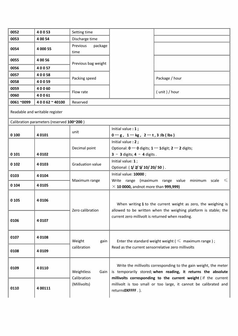
0052 4 0 0 53 Setting time
0053 4 00 54 Discharge time
0054 4 000 55 Previous package
time
0055 4 00 56 Previous bag weight
0056 4 0 0 57
0057 4 0 0 58 Packing speed Package / hour
0058 4 0 0 59
0059 4 0 0 60 Flow rate ( unit ) / hour
0060 4 0 0 61
0061 ~0099 4 0 0 62 ~ 40100 Reserved
Readable and writable register
Calibration parameters (reserved 100~200 )
0 100 4 0101 unit
Initial value : 1 ;
0 — g , 1 — kg , 2 — t , 3 :lb ( lbs )
0 101 4 0102
Decimal point
Initial value : 2 ;
Optional: 0 — 0 digits; 1 — 1digit; 2 — 2 digits;
3 – 3 digits; 4 – 4 digits .
0 102 4 0103 Graduation value Initial value: 1 ;
Optional: ( 1/ 2/ 5/ 10/ 20/ 50 ) .
0103 4 0104 Maximum range
Initial value: 10000 ;
Write range (maximum range value minimum scale ≤
× 10 0000, andnot more than 999,999) 0 104 4 0105
0 105 4 0106
Zero calibration
When writing 1 to the current weight as zero, the weighing is
allowed to be written when the weighing platform is stable; the
current zero millivolt is returned when reading. 0106 4 0107
0107 4 0108 Weight gain
calibration
Enter the standard weight weight ( ≤ maximum range ) ;
Read as the current sensorrelative zero millivolts 0108 4 0109
0109 4 0110 Weightless Gain
Calibration
(Millivolts)
Write the millivolts corresponding to the gain weight, the meter
is temporarily stored; when reading, it returns the absolute
millivolts corresponding to the current weight ( if the current
millivolt is too small or too large, it cannot be calibrated and
returns0XFFFF . ). 0110 4 00111

0111 4 0112
No code gain
calibration (weight)
Write and gain the weight value corresponding to millivolts.
Before writing this value, you must first write the gain millivolts.
When writing this register, use both to perform gain calibration.
Returns 0000H when read . 0 112 4 0113
0113 4 0114 Sensor sensitivity 3mV/V
(Note 2 ) .
0114 4 0115
Instrument sensor
voltage
The multimeter measures the voltage
between EX + and EX - . (Note 2 ) .
0115 4 0116
0 116 4 0117 Sensor maximum
range
Initial value: 10000 ; ( Note 2 ).
Write range (maximum range value minimum scale ≤
× 10 0000, andnot more than 999,999) 0 117 4 0118
0 118~ 0199 4 0119~ 40200 Reserved
System and communication parameters - weight parameters ( reserved 200~500 )
0 200 4 0201 Stable range Initial value : 2 ;
Stable range ( 0 ~ 9 9 d optional )Unit: d
0 201 4 0202 Judgment time Initial value: 0.3 ; range: 0.1~9.9. (unit s )
0 202 4 0203 Clear range Initial value: 50 ; Range : 1 -99units: %
0 203 4 0204 Zero tracking range Initial value: 0 ; Range : 0-9Unit: d
0 204 4 0205 Zero tracking time Initial value: 2.0 ; range:0.1~99.9 . (unit s )
0 205 4 0206 A/D conversion rate
Initial value: 2 ;
Optional: 0: 120 times / sec; 1 :24 0 times / sec; 2 : 480 times /
sec; 3: 9600 times / sec .
0206 ~ 0249 4 0207~ 40250 Reserved
System and communication parameters - filter parameters
0 250 4 0251 Stop filter level Initial value: 7 ; Range: 0 to 9
0 251 4 0252 Secondary filter
switch Initial value: 0 ; 1 : On 0 : Off
0 252 4 0253 Dynamic filter
switch Initial value: 0 ; 1 : On ; 0 : Off
0 253 4 0254 Feed filter level Initial value: 2 ; Range: 0 to 9
0254 4 0255 Fixed filter level Initial value: 7 ; Range: 0 to 9
0 255 4 0256 Unloading filter level Initial value: 1 ; Range: 0 to 9
0 256~ 0299 4 0257 ~ 40300 Reserved
System and communication parameters - function parameters
0 300 4 0301 Power-on automatic Initial value: 0 ; 1 : On ; 0 : Off

clear
0 301 40302 Automatic clear
interval
Initial value: 0 ;
Range : 0-99 has the bucket tocomplete the packing and then clear
the current weight.
0 302 40303 Running stability
timeout The initial value is 0 ; therange is 0 to 9 9.9 . (unit s )
0 303 40304 Setting method Initial value: 0 ; (range: 0 , 1 )
0 : judgment stable value ; 1 :delay setting
0 304 40305 Manual unloading Initial value: 0 ; 1 : On ; 0 : Off
0 305 40306 Fixed weight
retention Initial value: 0 ; 1 : On ; 0 : Off
0 306 40307 Adaptive level Initial value: 3 ; Range: 1 ~ 5
0 307 40308 Adaptive switch Initial value: 0 ; Range: 0 ~ 2
0308 ~ 0349 40309 ~ 4 0350 Reserved
System and communication parameters - structural parameters
0 350 40351 Scale body structure
Initial value: 0 ;
0 : There are bucket scales; 1 :No bucket scale; 2 : PLC mode; 3: ton
pack scale; 4 : Valve scale.
0 351 40352 Operating mode Initial value : 0 ;
0: single scale; 1: Interlock A;2: interlock B.
0 352 40353 Packaging mode Initial value: 1 ;
0: Gross weight packaging; 1:Net weight package.
0 353 40354 Bracket movement Initial value: 0 ;
0 : pneumatic; 1 : electric.
0 354 40355 Feeding method Initial value: 1 ;
0 : separate feeding ; 1 :combined feeding .
0 355 40356 Double scale loose
bag mode
Initial value: 0 ;
0 : no loose bag at the same time ;
1 : At the same time loose bag 1;
2 : At the same time loose bag2 .
0 356~ 0499 4035 7~ 40500 Reserved
Recipe parameters - quantitative value parameters ( reserved 500~100 0 )
0 500 40501 Recipe number Initial value 1 ; range: 1 to 20
0 501 40502
0 502 40503 Target value
Weight value writing range : ≤maximum range
0 503 40504
0 504 40505 Faster advance
0 505 40506
0 506 40507 Medium and early
advance 0 507 40508
0 508 40509 Drop difference

0 509 40510
0 510 40511 Zero zone value
0 511 40512
0 512~ 0549 40513 ~ 40550 Reserved
Recipe parameter - time parameter
0 550 40551 Delay before feeding Initial value: 0. 5 ; range: 0 to99.9 . (unit s )
0 551 40552 Quickly add time . Initial value: 09; range: 0 to99.9. (unit s )
0 552 40553
Sino-Canada banned
time Initial value: 0. 9 ; range: 0 to99.9 . (unit s )
0 553 40554 Slowly add time Initial value: 0. 9 ; range: 0 to99.9 . (unit s )
0 554 40555
Fixed value
retention time Initial value: 0. 5 ; range: 0 to99.9 . (unit s )
0 555 40556 Delay after pocket Initial value: 0. 5 ; range: 0 to99.9 . (unit s )
0 556 4 0557
Time before loose
bag Initial value: 0. 5 ; range: 0 to99.9 . (unit s )
0 557 40558 Unloading delay Initial value: 0. 5 ; range: 0 to99.9 . (unit s )
0 558~ 0599 40559~40600 Reserved
Recipe parameters - super low error detection parameters
0 600 40601
Super low detection
switch Initial value: 0 ; 1 : On ; 0 : Off
0 601 40602
Super low pause
switch Initial value: 0 ; 1 : On ; 0 : Off
0 602 40603
Super low alarm
time . Initial value: 10; range: 0 ~999. (unit s )
0 603 40604 Tolerance value
Weight value writing range : ≤maximum range 0 604 40605
0 605 40606 Due to thedifference
0 606 40607
0 607 40608 Underfeed switch Initial value: 0 ; 1 : On ; 0 : Off.
0 608
40609
Undershoot
maximum
replenishment times First: 1; range: 1 ~ 99.
0 609 40610
Feeding effective
time Initial value: 0.5 ; range: 0 to 99 .9 . (unit s )
0 610 406011 Invalid feeding time Initial value: 0.5 ; range: 0 to 99 .9 . (unit s )
Recipe parameters - drop correction parameters
0 611 406012
Drop correction
switch Initial value: 0 ; 1 : On ; 0 : Off .
0 612 406013 Drop correction Initial value: 1 ; Range: 1~99 .
0 613 406014
Drop correction
range Range: 2.0 ; Range: 0 to 9.9 ( unit:% )

0 614 406015 Drop correction
Initial value: 1 ;
Optional: 0--100 % correction; 1--50% correction; 2 - 25%correction.
Recipe parameters - slow plus jog
0 615 406016 Slow plus jog switch Initial value: 0 ; 1 : On ; 0 : Off .
0 616 406017 Jog effective time Initial value : 0.5 ; range: 0 to9.9 . (unit s )
0 617 406018 Jog invalid time Initial value : 0.5 ; range: 0 to9.9 . (unit s )
Recipe parameters - there are bucket parameters
0 618 406019
Single combination
number First: 1; range: 0 ~ 99.
0 619~ 0649 40620 ~ 40650 Reserved
Recipe parameters - no bucket parameters
0 650 406051
Bagging delay start
time again Initial value : 4.0 ; range: 0 to 99 .9 . (unit s )
0 651~ 0699 406052~40700 Reserved
Recipe parameters - PLC mode
0 700 40701
Super difference 0 ~ maximum range
0 701 40702
0 702 40703 Underbalance 0 ~ maximum range
0 703 40704
0 704 40705 Upper limit 0 ~ maximum range
0 705 40706
0 706 40707 lower limit 0 ~ maximum range
0 707 40708
0 708~ 0749 40709~40750 Reserved
Recipe parameters - tons of scale mode
0 750 40751 Hanger delay time Initial value : 0.5 ; range: 0 to 99.9 . (unit s )
0 751 40752 Bracket automatic
rise switch Initial value: 0 ; 1 : On ; 0 : Off
0 752 40753 Bracket uplink delay
time Initial value: 5.0; range: 0 ~ 99.9. (unit s )
0 753 40754 Bracket down delay
time Initial value: 5.0; range: 0 ~ 99.9. (unit s )
0 754 40755 Metering bracket
uplink timeout Initial value: 5.0; range: 0 ~ 99.9. (unit s )
0 755 40756 Metering bracket
downlink timeout Initial value: 5.0; range: 0 ~ 99.9. (unit s )
0 756 40757 Blowing time Initial value : 0.5 ; range: 0 to 99.9 . (unit s )
0 757 40758 Belt A running
time (reserved) Initial value: 5.0; range: 0 ~ 99.9. (unit s )

0 758 40759 Belt B running
time (reserved) Initial value: 5.0; range: 0 ~ 99.9. (unit s )
0 759~ 0799 40760~40800 Reserved
Recipe parameters - valve port mode
0 800 40801 Bag delay time Initial value : 0.5 ; range: 0 to 99.9 . (unit s )
0 801 40802 Bag effective time Initial value : 0.5 ; range: 0 to 99.9 . (unit s )
0 802 40803 Push bag delay time Initial value : 0.5 ; range: 0 to 99.9 . (unit s )
0 803 40804 Push bag effective
time Initial value : 0.5 ; range: 0 to 99.9 . (unit s )
0 804~ 0999 40 804~ 41000 Reserved
Peripheral parameters - beat ( dock ) bag parameters ( reserved 1000~1200 )
1000 41001 Bag mode
Initial value: 0 ;
Optional:
0 : Do not shoot the bag ;
1 : After the fixed value, the bag is taken ;
2 : Shooting bag in the feeding ;
3: After the addition averagevalue and shot bags.
There are buckets to set: 0,1 ;
No bucket can be set: 0~3 .
1001 41002 Bag start weight Initial value: 0 ; Range: 0 ~Maximum range.
1002 41003
1003 41004 Number of shots in
the feed
Initial value: 0 ; range: 0~99 .
Set the parameters for the number of shots in the feed .
1004 41005 Number of shots
after setting
Initial value: 4 ; Range: 0~99 .
Set the parameters for the number of shots after the value is set .
1005 41006 Delay before the
bag
Initial value: 0.5 ; range : 0~99.9. (unit s )
After the bag is started , the bag output is valid after this delay time.
1006 41007 Bag time Initial value: 0.5 ; range: 0~99.9. (unit s )
During the on-off cycle of the bag, the bag output valid time.
1007 41008 Bag time invalid Initial value: 0.5 ; range : 0~99.9. (unit s )
In the on-off cycle of the bag, the bag output invalid time.
1008 41009
Extra shot bag
output effective
time
Initial value: 0 ; range : 0~99.9 .(unit s )
1009~1019 41010 ~ 41020 Reserved
Peripheral parameters - coding parameters
1020 41021 Code switch Initial value: 0 ; 1 : On ; 0 : Off .
1021 41022 Code start delay Initial value: 0. 5 ; range: 0 to 99 .9 . (unit s )
1022 41023 Code valid time Initial value: 0. 5 ; range: 0 to 99 .9 . (unit s )
1023 41024
Not be allowed to
add a code
whenunloading
Initial value: 0 ;
0 : The discharge output or the feed output is allowed to start
during the coding process;

1 : The discharge output or feed output is not allowed to start
during the coding process.
1024~1029 41025~41030 Reserved
Peripheral parameters - sewing machine parameters
1030 41031 Sewing machine
start delay Initial value: 0. 5 ; range: 0 to 99 .9 . (unit s )
1031 41032
Sewing machine
output effective
time
Initial value: 4.0 ; range: 0 to 99 .9 . (unit s )
1032 41033 Tangent output time Initial value: 0. 5 ; range: 0 to 99 .9 . (unit s )
1033 41034 Delay before sewing
machine Initial value: 0. 5 ; range: 0 to 99 .9 . (unit s )
1034~1039 41035~41040 Reserved
Peripheral parameters - unloading rapping parameters
1040 41041 Unloading rapping
switch Initial value: 0 ; 1 : On ; 0 : Off .
1041 41042 Unloading effective
time Initial value: 2. 0 ; range: 0 to9.9 . (unit s )
1042 41043 Unloading rapping
effective time Initial value: 0. 5 ; range: 0 to9.9 . (unit s )
1043 41044 Unloading rapping
invalid time Initial value: 0. 5 ; range: 0 to9.9 . (unit s )
1044 41045 Unloading
frequency Initial value: 10 ; Range: 0 to 99 .
1045~1049 41046~41050 Reserved
Peripheral parameters - loading and unloading timeout judgment parameters
1050 41051
Loading and
unloading timeout
judgment switch
Initial value: 0 ; 1 : On ; 0 : Off .
1051 41052 Fast timeout Initial value: 5.0 ; range: 0 to 99 .9 . (unit s )
1052 41053 Medium plus
timeout Initial value: 5.0 ; range: 0 to 99 .9 . (unit s )
1053 41054 Slow plus timeout Initial value: 5.0 ; range: 0 to 99 .9 . (unit s )
1054 41055 Discharge timeout Initial value: 5.0 ; range: 0 to 99 .9 . (unit s )
1055~1059 41056~41060 Reserved
Peripheral parameters - auxiliary pulse parameters
1060 41061
Auxiliary
pulse 1execution
total time
Initial value: 0.0 ;
Range: 0 to 9 9 9.9 . (unit s )
1061 41062
Auxiliary
pulse 1effective
time
Initial value: 10.0 ;
Range: 0 to 9 9 9.9 . (unit s )

1062 41063 Auxiliary
pulse 1invalid time
Initial value: 10.0 ;
Range: 0 to 9 9 9.9 . (unit s )
1063 41064
Auxiliary
pulse 2execution
total time
Initial value: 0.0 ;
Range: 0 to 9 9 9.9 . (unit s )
1064 41065
Auxiliary
pulse 2effective
time
Initial value: 10.0 ;
Range: 0 to 9 9 9.9 . (unit s )
1065 41066 Auxiliary
pulse 2invalid time
Initial value: 10.0 ;
Range: 0 to 9 9 9.9 . (unit s )
1066 41067
Auxiliary
pulse 3execution
total time
Initial value: 0.0 ;
Range: 0 to 9 9 9.9 . (unit min )
1067 41068
Auxiliary
pulse 3effective
time
Initial value: 10.0 ;
Range: 0 to 9 9 9.9 . (unit min )
1068 41069 Auxiliary
pulse 3invalid time
Initial value: 10.0 ;
Range: 0 to 9 9 9.9 . (unit min )
1069 41070
Auxiliary
pulse 4execution
total time
Initial value: 0.0 ;
Range: 0 to 9 9 9.9 . (unit min )
1070 41071
Auxiliary
pulse 4effective
time
Initial value: 10.0 ;
Range: 0 to 9 9 9.9 . (unit min )
1071 41072 Auxiliary pulse 4
invalid time
Initial value: 10.0 ;
Range: 0 to 9 9 9.9 . (unit min )
1072~1079 41073~41080 Reserved
Peripheral parameters - conveyor
1080 41081 Conveyor switch Initial value: 0 ; 1 : On ; 0 : Off .
1081 41082 Conveyor start delay Initial value: 0. 5 ; range: 0 to 99 .9 . (unit s )
1082 41083 Conveyor running
time Initial value: 4.0 ; range: 0 to 99 .9 . (unit s )
108 3 ~ 1089 4108 4 ~ 41090 Reserved
Peripheral parameters - print parameters
1090 1091 Automatic print
switch Initial value: 0 , 1 : On ; 0 : Off
1091 1092 Print format Initial value : 0 ;
0 : 24 columns of printing ; 1 :32 columns of printing .
1092 1093 Print language Initial value : 0 ; 0 : Chinese; 1: E nglish .
1093 1094 Print the number of
lines Initial value: 3 ; Range: 0 to 9 .
1094~1199 4 1095 ~41200 Reserved

Auxiliary logic programming 1 -6 ( reserved 1200~1400 )
1200 41 201 Types of
Initial value : 0 ; range 0~5 .
0 : off
1 : Delay on
2 : Delayed disconnection
3 : Delay on and delay off
4 : Invalid - valid edge trigger
5 : valid - invalid edge trigger
1201 41 202 Trigger signal
Initial value : 0 ; range: 0~64 .
Can be selected from the definition of the trigger input port , fixed
digital input port1~12 , digital output definition, weight value
trigger.
1202 41 203 Trigger input signal
port
Initial value : 0 ; range 0~12 .
Select the digital input port 0~12corresponding to this function
signal , and input port 0 means that this function is not defined.
1203 41 204 Output signal port
Initial value : 0 ; range 0~16 .
Select the digital output port0~16 corresponding to the function
signal , and the output port- 0 means that the function is not
defined.
1204 41 205 Delay on time
Initial value : 0 ; range: 0~99.9 .(unit s )
After the trigger signal is valid, the logic output signal is valid after
the delay.
1205 41 206 Delayed off time
Initial value : 0 ; range: 0~99.9 .(unit s )
After the trigger signal is invalid, the logic output signal will be
invalid after the delay.
1206 41 207 Signal output
effective time
Initial value : 0 ; range: 0~99.9 .(unit s )
The duration after the logic output signal is valid, and becomes
invalid after the end of the time.
1207 41 208
Threshold weight
Initial value: 0 ; Range:0~999999
When the trigger signal selects "Threshold Weight", the current
weight is compared to this value. 1208 41 209
1209 ~ 1219 41 210 ~41220 Reserved
Auxiliary logic programming 2
1220 41 221 Types of
Initial value : 0 ; range 0~5 .
0 : off
1 : Delay on
2 : Delayed disconnection
3 : Delay on and delay off
4 : Invalid - valid edge trigger
5 : valid - invalid edge trigger
1221 41 222 Trigger signal Initial value : 0 ; range: 0~64 .
Can be selected from the definition of the trigger input port , fixed

digital input port1~12 , digital output definition, weight value
trigger.
1222 41 223 Trigger input signal
port
Initial value : 0 ; range 0~12 .
Select the digital input port 0~12corresponding to this function
signal , and input port 0 means that this function is not defined.
1223 41 224 Output signal port
Initial value : 0 ; range 0~16 .
Select the digital output port0~16 corresponding to the function
signal , and the output port- 0 means that the function is not
defined.
1224 41 225 Delay on time
Initial value : 0 ; range: 0~99.9 .(unit s )
After the trigger signal is valid, the logic output signal is valid after
the delay.
1225 41 226 Delayed off time
Initial value : 0 ; range: 0~99.9 .(unit s )
After the trigger signal is invalid, the logic output signal will be
invalid after the delay.
1226 41 227 Signal output
effective time
Initial value : 0 ; range: 0~99.9 .(unit s )
The duration after the logic output signal is valid, and becomes
invalid after the end of the time.
1227 41228
Threshold weight
Initial value: 0 ; Range: 0~999999
When the trigger signal selects "Threshold Weight", the current
weight is compared to this value. 1228 41229
1229 ~1239 41 230 ~ 41240 Reserved
Auxiliary logic programming 3
1240 41 241 Types of
Initial value : 0 ; range 0~5 .
0 : off
1 : Delay on
2 : Delayed disconnection
3 : Delay on and delay off
4 : Invalid - valid edge trigger
5 : valid - invalid edge trigger
1241 41 242 Trigger signal
Initial value : 0 ; range: 0~64 .
Can be selected from the definition of the trigger input port , fixed
digital input port1~12 , digital output definition, weight value
trigger.
1242 41 243 Trigger input signal
port
Initial value : 0 ; range 0~12 .
Select the digital input port 0~12corresponding to this function
signal , and input port 0 means that this function is not defined.
1243 41 244 Output signal port
Initial value : 0 ; range 0~16 .
Select the digital output port0~16 corresponding to the function
signal , and the output port- 0 means that the function is not
defined.
1244 41 245 Delay on time Initial value : 0 ; range: 0~99.9 .(unit s )

After the trigger signal is valid, the logic output signal is valid after
the delay.
1245 41 246 Delayed off time
Initial value : 0 ; range: 0~99.9 .(unit s )
After the trigger signal is invalid, the logic output signal will be
invalid after the delay.
1246 41 247 Signal output
effective time
Initial value : 0 ; range: 0~99.9 .(unit s )
The duration after the logic output signal is valid, and becomes
invalid after the end of the time.
1247 41248
Threshold weight
Initial value: 0 ; range: 0~999999.
When the trigger signal selects "Threshold Weight", the current
weight is compared to this value. 1248 41249
1249 ~ 1259 41 250 ~41260 Reserved
Auxiliary logic programming 4
1260 41 261 Types of
Initial value : 0 ; range 0~5 .
0 : off
1 : Delay on
2 : Delayed disconnection
3 : Delay on and delay off
4 : Invalid - valid edge trigger
5 : valid - invalid edge trigger
1261 41 262 Trigger signal
Initial value : 0 ; range: 0~64 .
Can be selected from the definition of the trigger input port , fixed
digital input port1~12 , digital output definition, weight value
trigger.
1262 41 263 Trigger input signal
port
Initial value : 0 ; range 0~12 .
Select the digital input port 0~12corresponding to this function
signal , and input port 0 means that this function is not defined.
1263 41 264 Output signal port
Initial value : 0 ; range 0~16 .
Select the digital output port0~16 corresponding to the function
signal , and the output port- 0 means that the function is not
defined.
1264 41 265 Delay on time
Initial value : 0 ; range: 0~99.9 .(unit s )
After the trigger signal is valid, the logic output signal is valid after
the delay.
1265 41 266 Delayed off time
Initial value : 0 ; range: 0~99.9 .(unit s )
After the trigger signal is invalid, the logic output signal will be
invalid after the delay.
1266 41 267 Signal output
effective time
Initial value : 0 ; range: 0~99.9 .(unit s )
The duration after the logic output signal is valid, and becomes
invalid after the end of the time.
1267 41268 Threshold weight
Initial value: 0 , range:0~999999 .
When the trigger signal selects "Threshold Weight", the current 1268 41269

weight is compared to this value.
1269 ~ 1279 41 270 ~ 41280 Reserved
Auxiliary logic programming 5
1280 41281 Types of
Initial value : 0 ; range 0~5 .
0 : off
1 : Delay on
2 : Delayed disconnection
3 : Delay on and delay off
4 : Invalid - valid edge trigger
5 : valid - invalid edge trigger
1281 41282 Trigger signal
Initial value : 0 ; range: 0~64 .
Can be selected from the definition of the trigger input port , fixed
digital input port1~12 , digital output definition, weight value
trigger.
1282 41283 Trigger input signal
port
Initial value : 0 ; range 0~12 .
Select the digital input port 0~12corresponding to this function
signal , and input port 0 means that this function is not defined.
1283 41284 Output signal port
Initial value : 0 ; range 0~16 .
Select the digital output port0~16 corresponding to the function
signal , and the output port- 0 means that the function is not
defined.
1284 41285 Delay on time
Initial value : 0 ; range: 0~99.9 .(unit s )
After the trigger signal is valid, the logic output signal is valid after
the delay.
1285 41286 Delayed off time
Initial value : 0 ; range: 0~99.9 .(unit s )
After the trigger signal is invalid, the logic output signal will be
invalid after the delay.
1286 41287 Signal output
effective time
Initial value : 0 ; range: 0~99.9 .(unit s )
The duration after the logic output signal is valid, and becomes
invalid after the end of the time.
1287 41288
Threshold weight
Initial value: 0 ; Range: 0~Maximum range.
When the trigger signal selects "Threshold Weight", the current
weight is compared to this value. 1288 41289
1289 ~1299 41290~41300 Reserved
Auxiliary logic programming 6
1300 41301 Types of
Initial value : 0 ; range 0~5 .
0 : off
1 : Delay on
2 : Delayed disconnection
3 : Delay on and delay off
4 : Invalid - valid edge trigger
5 : valid - invalid edge trigger

1301 41302 Trigger signal
Initial value : 0 ; range: 0~64 .
Can be selected from the definition of the trigger input port , fixed
digital input port1~12 , digital output definition, weight value
trigger.
1302 41303 Trigger input signal
port
Initial value : 0 ; range 0~12 .
Select the digital input port 0~12corresponding to this function
signal , and input port 0 means that this function is not defined.
1303 41304 Output signal port
Initial value : 0 ; range 0~16 .
Select the digital output port 0~16 corresponding to the function
signal, and the output port- 0 means that the function is not
defined.
1304 41305 Delay on time
Initial value : 0 ; range: 0~99.9 .(unit s )
After the trigger signal is valid, the logic output signal is valid after
the delay.
1305 41306 Delayed off time
Initial value : 0 ; range: 0~99.9 .(unit s )
After the trigger signal is invalid, the logic output signal will be
invalid after the delay.
1306 41307 Signal output
effective time
Initial value : 0 ; range: 0~99.9 .(unit s )
The duration after the logic output signal is valid, and becomes
invalid after the end of the time.
1307 41308
Threshold weight
Initial value: 0 ; range: 0~999999.
When the trigger signal selects "Threshold Weight", the current
weight is compared to this value. 1308 41309
1309 ~ 1399 41310~41400 Reserved
Motor parameters - feeding mode ( reserved 1400~1600)
1400 41400
Motor group
number used in the
current recipe
Initial value: 0 ; Range: 0~4
1401 41402 Feed mode
Initial value : 0 ;
Optional:
0 : pneumatic feeding ; 1 :stepping motor feeding;
2 : Ordinary motor feeding .
1402 41403 Feeding gate closing
timeout Initial value: 4.0 ; range: 0~99.9. (unit s )
1403 41404
Feed gate
in-position signal
type
Initial value: 0 ;
Optional:
0 : The signal is in place when it is valid;
1 : When the signal is invalid, it is in place .
1404 41405 Motor group
number Initial value: 0 , range: 0~4
1405 41406 Feed motor
frequency Initial value : 12000 , range:1~50000Hz

1406 41407
Adding material to
slow down and
adding the required
number of pulses
Initial value : 1800 ; range:1~60000 .
1408 41409
The number of
pulses required for
feeding to close
Initial value : 4300 ; range:1~60000 .
1410 41411
Feeding off to fast
increase the number
of pulses required
Initial value : 7750 ; range:1~60000 .
1412 41413
Feed switch
direction signal
status
Initial value : 0 ;
Optional:
0 : the door opening directionwhen the signal is valid ;
1 : The door opening directionis when the signal is invalid .
1413 41414 Feed motor starting
frequency
Initial value : 2000 ;
Range: 0~50000Hz
(This value should preferably not be greater than the feeding motor
frequency)
1414 41415 Feed motor
acceleration time
Feed motor acceleration time
Initial value: 200 ;
Range: 0~9999 . (unit s )
1415 41416 Feed motor
deceleration time
Feed motor deceleration time
Initial value: 50 ;
Range: 0~9999 . (in ms )
1416 41417 Quickly open the
door
Initial value: 0.80 ;
Range : 0~99.99 . (unit s )
1417 41418 China and
Canadaopening time
Initial value: 0.40 ;
Range: 0~99.99 . (unit s )
1418 41419 Slow opening time Initial value: 0.20 ;
Range: 0~99.99 . (unit s )
1419 41420 Bag mode
Initial value: 0 ;
Optional:
0 : pneumatic clamp loose bag;
1 : stepper motor clip loose bag ;
2 : motor double limit clip loose bag;
3 : Motor single limit clip loose bag .
1420 41421 Loose bagprocesstimeout Initial value: 3.0 ; Range: 0 ~ 99.9 . (unit s )
1421 41422 Baggingprocesstimeout Initial value: 3.0 ; range: 0~99.9 . (unit s )
1422 41423 Loose bag in place signal type Initial value: 0 ;

Optional:
0 : The signal is in place when it is valid ;
1 : When the signal is invalid, it is in place .
1423 41424 Bag motorfrequency Initial value: 30000 ; Range: 1~50000 Hz .
1 424 41425 Matsumotomotorfrequency Initial value: 20000 ; range: 1~50000 Hz .
1425 41426 The number of pulses required
for the bag Initial value: 12000 ; range: 1~60000 .
1426 41427
1427 41428 Bag direction signal status
Initial value: 0 ;
Optional:
0 : when the signal is invalid, it is the direction of
the pocket;
1 : When the signal is valid, it is the direction of the
pocket.
1428 41429 Bag motor starting frequency
Initial value: 2000 ; range: 0 ~ 50000 Hz .
(This value cannot be greater than the pocket
frequency)
1429 41430 Bag motor acceleration time Initial value: 200 ;
Range: 0~9999 . (in ms )
1430 41431 Bag motor deceleration time Initial value: 50 ; Range: 0~9999 (in ms ) .
1431 41432 Loose bageffective time Initial value: 0.5 , range: 0~99.99 . (unit s )
1432 41433 Discharge mode
Initial value: pneumatic mode;
0 , pneumatic mode;
1. Stepper motor unloading;
2 , motor single limit discharge;
3 , the motor double limit discharge;
4. The motor rotates and unloads in one direction.
1433 41434 Discharge closing timeout Initial value : 3.0 ; range: 0 ~ 99.9 . (unit s )
1434 41435 Unloading timeout Initial value : 3.0 ; range: 0 ~ 99 .9 . (unit s )
1435 41436 Discharge in place signal type
Initial value: 0 ;
Optional:
0 , the signal is in place when it is valid .
1. When the signal is invalid, it is in place .
1436 41437 Unloading limit real-time
detection switch Initial value : 0 ; 0 : off ; 1 : on.
1437 41438 Unloading door motor
frequency Initial value : 30000 ; range: 1~50000 ( Hz ) .
1438 41439 Discharge closing motor
frequency Initial value : 20000 ; range: 1~50000 ( Hz ) .
1439 41410 Number ofpulsesrequired for
unloading Initial value : 12000 ; range: 1~60000 .
1440 41411

144 1 41412 Discharge direction signal status
Initial value : 0 ;
Optional:
0 : the door opening direction when the signal is
invalid
1: valid signal to the door opening direction
1442 41416 Unloading motor starting
frequency
Initial value: 2000 ; range: 1~50000 ( Hz ) .
(This value cannot be greater than the discharge
frequency)
1443 41414 Unloading motor acceleration
time
Initial value: 200 ;
Range: 0~9999 . (in ms )
1444 41415 Unloading motor deceleration
time
Initial value: 50 ;
Range: 0~9999 . (in ms )
1445 41416 Unloading door opening time Initial value: 1.00 ;
Range: 0~99.99 . (unit s )
1446~1599 41417~41600 Reserved
Communication parameters - serial port 1 parameters ( reserved 1600~1700 ) 485
1600 41601 Slave number Initial value: 1 ; 1 ~ 9 9 optional.
1601 41602 communication method
0 : Modbus-RTU ;
1 : Print
2 : continuous mode
3 : MD-R (compatible with 01. version)
1602 41603 Baud rate
0 : 9600
1 : 119200
2 : 38400
3 : 57600
4 : 115200
1603 41604 Data Format
Communication data format selection (data bit,
parity bit, stop bit . E : even parity; N : no parity )
0 : 8-E-1
1 : 8-N-1
2 : 7-E-1
3 : 7-N-1
1604 41605 High and low words
Initial value : 0 : The high word is in the
front low word after ;
Range : 0-1
0 : the high word is in the front low word after ;
1 : The low word is in the front high word .
Communication parameters - serial port 2 parameters 232
1605 41606 Slave number Initial value: 1 ; 1 ~ 9 9 optional.
1606 41607 communication method
0 : Modbus-RTU ;
1 : Print
2 : continuous mode
3 : MD-R (compatible with 01. version)
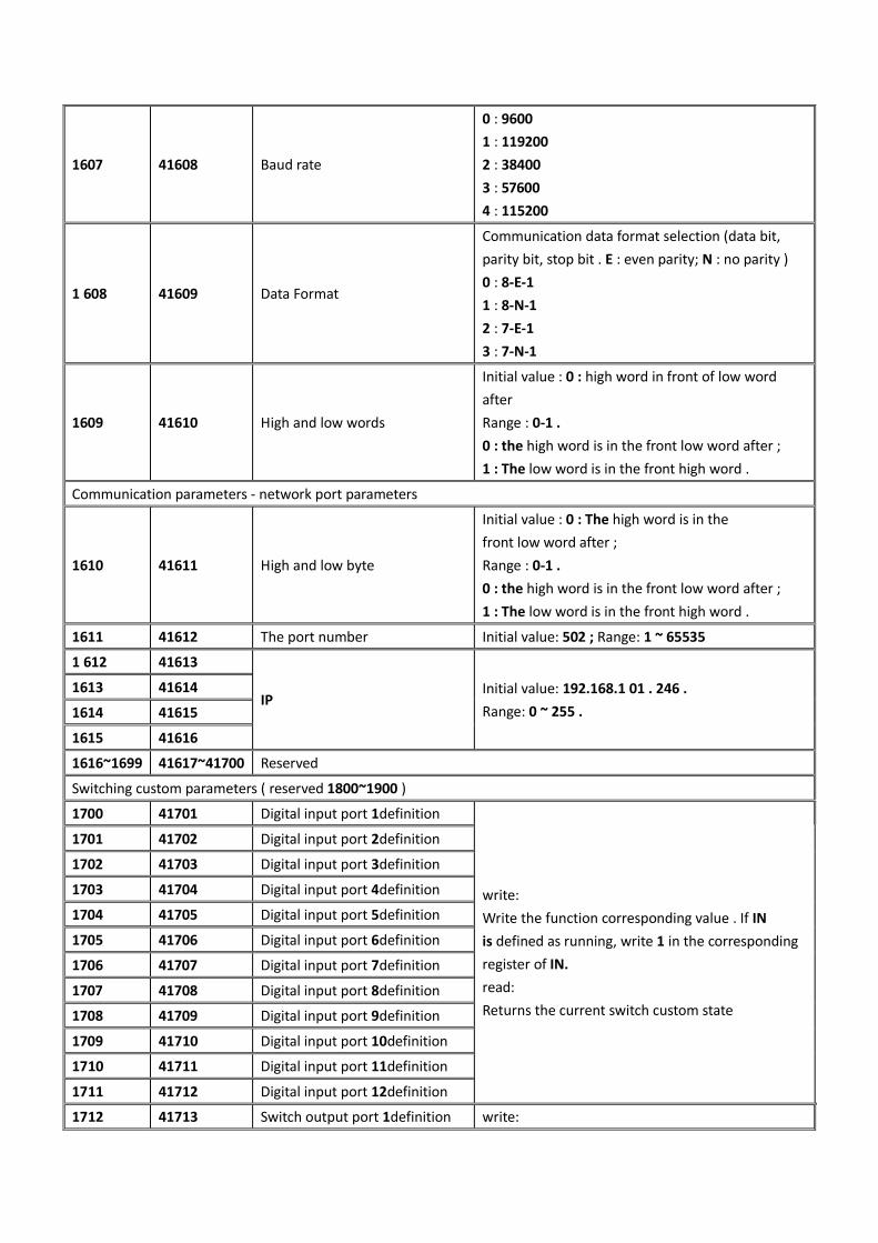
1607 41608 Baud rate
0 : 9600
1 : 119200
2 : 38400
3 : 57600
4 : 115200
1 608 41609 Data Format
Communication data format selection (data bit,
parity bit, stop bit . E : even parity; N : no parity )
0 : 8-E-1
1 : 8-N-1
2 : 7-E-1
3 : 7-N-1
1609 41610 High and low words
Initial value : 0 : high word in front of low word
after
Range : 0-1 .
0 : the high word is in the front low word after ;
1 : The low word is in the front high word .
Communication parameters - network port parameters
1610 41611 High and low byte
Initial value : 0 : The high word is in the
front low word after ;
Range : 0-1 .
0 : the high word is in the front low word after ;
1 : The low word is in the front high word .
1611 41612 The port number Initial value: 502 ; Range: 1 ~ 65535
1 612 41613
IP Initial value: 192.168.1 01 . 246 .
Range: 0 ~ 255 .
1613 41614
1614 41615
1615 41616
1616~1699 41617~41700 Reserved
Switching custom parameters ( reserved 1800~1900 )
1700 41701 Digital input port 1definition
write:
Write the function corresponding value . If IN
is defined as running, write 1 in the corresponding
register of IN.
read:
Returns the current switch custom state
1701 41702 Digital input port 2definition
1702 41703 Digital input port 3definition
1703 41704 Digital input port 4definition
1704 41705 Digital input port 5definition
1705 41706 Digital input port 6definition
1706 41707 Digital input port 7definition
1707 41708 Digital input port 8definition
1708 41709 Digital input port 9definition
1709 41710 Digital input port 10definition
1710 41711 Digital input port 11definition
1711 41712 Digital input port 12definition
1712 41713 Switch output port 1definition write:
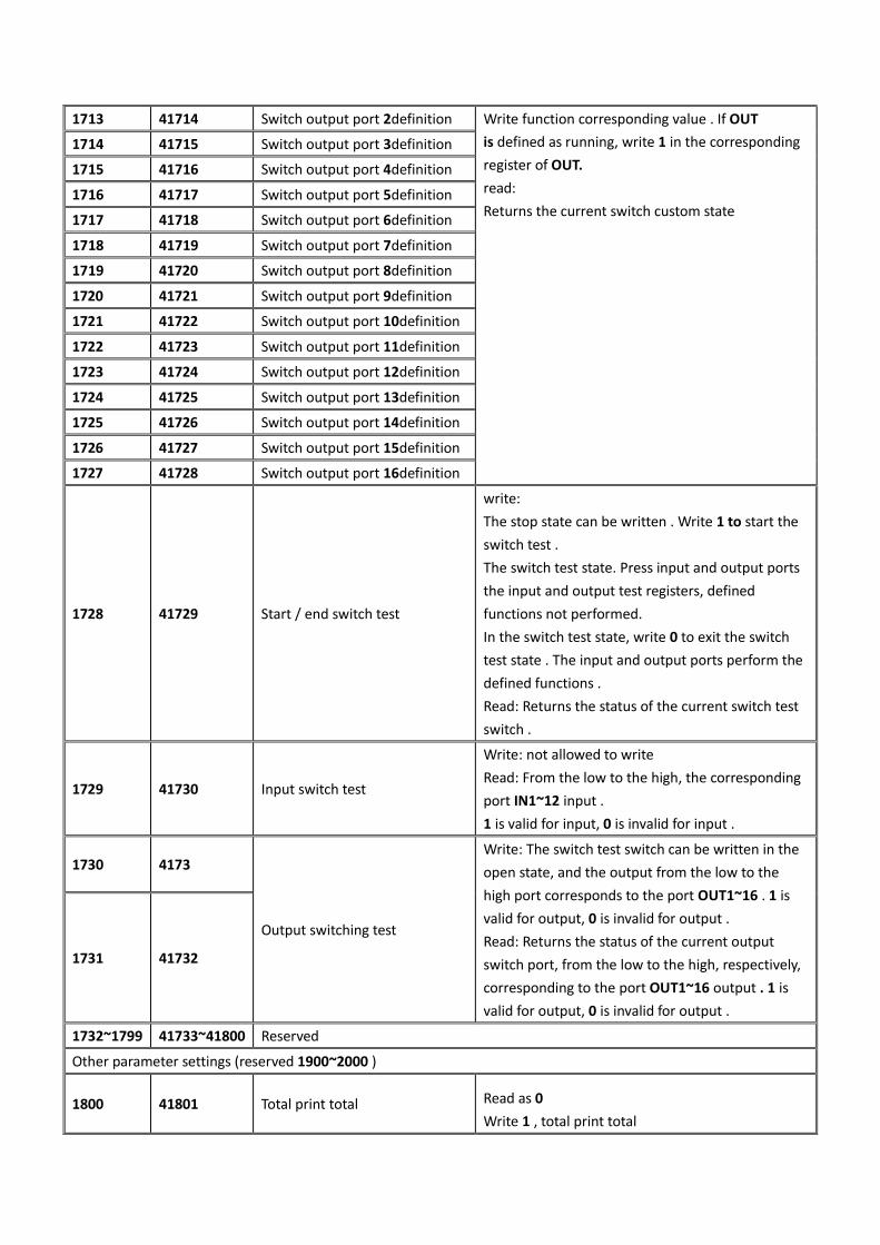
1713 41714 Switch output port 2definition Write function corresponding value . If OUT
is defined as running, write 1 in the corresponding
register of OUT.
read:
Returns the current switch custom state
1714 41715 Switch output port 3definition
1715 41716 Switch output port 4definition
1716 41717 Switch output port 5definition
1717 41718 Switch output port 6definition
1718 41719 Switch output port 7definition
1719 41720 Switch output port 8definition
1720 41721 Switch output port 9definition
1721 41722 Switch output port 10definition
1722 41723 Switch output port 11definition
1723 41724 Switch output port 12definition
1724 41725 Switch output port 13definition
1725 41726 Switch output port 14definition
1726 41727 Switch output port 15definition
1727 41728 Switch output port 16definition
1728 41729 Start / end switch test
write:
The stop state can be written . Write 1 to start the
switch test .
The switch test state. Press input and output ports
the input and output test registers, defined
functions not performed.
In the switch test state, write 0 to exit the switch
test state . The input and output ports perform the
defined functions .
Read: Returns the status of the current switch test
switch .
1729 41730 Input switch test
Write: not allowed to write
Read: From the low to the high, the corresponding
port IN1~12 input .
1 is valid for input, 0 is invalid for input .
1730 4173
Output switching test
Write: The switch test switch can be written in the
open state, and the output from the low to the
high port corresponds to the port OUT1~16 . 1 is
valid for output, 0 is invalid for output .
Read: Returns the status of the current output
switch port, from the low to the high, respectively,
corresponding to the port OUT1~16 output . 1 is
valid for output, 0 is invalid for output .
1731 41732
1732~1799 41733~41800 Reserved
Other parameter settings (reserved 1900~2000 )
1800 41801 Total print total Read as 0
Write 1 , total print total

1801 41802 Print recipe accumulation
Read as 0
Write 100 to print the current recipe accumulation
Write 1-20 , print the corresponding formula
accumulation
Write 101 to print all recipes
1802 41803 Print user accumulation
Read as 0
Write 100 to print the current user cumulative
Write 0-9 , print the corresponding user
cumulative
Write 101 , print all user cumulative
1803 41804 reset
8800 all parameters ( including school scales )
8801 all parameters ( excluding calibration scales
included ) 8802 reset
recipe parameters
8803 reset system and communication
8804 reset peripheral parameters
8805 reset motor parameters
880 6 reset calibration scale
880 7 reset switch
880 8 reset auxiliary logic parameters
1804 41805 Parameter backup
read:
0: There is no backup parameter currently;
1: There are currently backup parameters.
write:
Write 9900 execution parameter backup;
Write 9901 to perform a recovery backup;
Write 9902 to perform a delete backup .
1805 41806 Backup date
Read only 1806 41807
18 07 41808 Backup time
1808 41809
1809 41810 year 0 -99
1810 41811 month 1 -12
1811 41812 day 1 -31
1812 41813 Time 0-23
1813 41814 Minute 0 -59
1814 41815 second 0 -59
1815 41816 Clear total accumulation Write 1 clear total accumulation
1816 41817 Clear recipe accumulation
Write 1-20 to clear the corresponding accumulated
data ;
Write 100 to clear the current recipe
accumulation ;
Write 101 clears all recipe accumulations .

1817 41818 Clear user accumulation
Read as 0.
Write 0-9 to clear the corresponding user
accumulation ;
Write 100 to clear the current user accumulation ;
Write 101 clears all user accumulations .
Batch setting
1950 41951 batch Initial value: 0 ; range: 0 ~ 50000 .
1951 41952 Remaining batch Read only
1952~1999 41953~42000 Reserved
Formula target value (reserved 2000~2300 )
2000 42001 Formula 1target value Initial value : 0 .
2001 42002
2002 42003 Recipe 2target value Initial value : 0 .
2003 42004
...... ......
2038 42039 Recipe 20target value Initial value : 0 .
2039 42040
Cumulative weight
2040 42041 Total cumulative weight
is 6digits
Read only 2041 42042
2042 42043 The total cumulative weight
low 9 2043 42044
2044 42045 Total accumulated number of
packets Read only
2045 42046
2046 42047 Formula 1cumulative weight
is 6digits high
Read only
2047 42048
2048 42049 Formulation 1cumulative weight
low 9 2049 42050
2050 42051 Formula 1cumulative count
2051 42052
...... ......
2160 42161 Formulation 6High 20cumulative
weight 2161 42162
2162 42163 Formulation20 cumulative
weight low 9 2163 42164
2164 42165 Formula 20cumulative times
2165 42166

User cumulative weight and number of times
2166 42167 User 0cumulative weight
is 6digits high
Read only
2167 42168
2168 42169 User 0cumulative weight
is 9digits lower 2169 42170
2170 42171 User 0cumulative times
2171 42172
2172 42173 User 1 has acumulative weight
of 6digits 2173 42174
2174 42175 1 usercumulative weight low 9
2175 42176
2176 42177 User 1cumulative count
2177 42178
2178 42179 User 2cumulative weight
is 6digits high 2179 42180
2180 42181 2 usersaccumulated weight
low 9 2181 42182
2182 42183 User 2cumulative times
2183 42184
2184 42185 User 3cumulative weight
is 6digits 2185 42186
2186 42187 Usercumulative weight low 93
2187 42188
2188 42189 User 3cumulative times
2189 42190
2190 42191 User 4cumulative weight
is 6digits 2191 42192
2192 42193 4 usersaccumulated weight
low 9 2193 42194
2194 42195 User 4cumulative times
2195 42196
2196 42197 User 5cumulative weight
is 6digits 2197 42198
2198 42199 Usercumulative weight low 95
2199 42200
2200 42201 User 5cumulative times
2201 42202
2202 42203 User 6cumulative weight
is 6digits 2203 42204

2204 42205 6 usersaccumulated weight
low 9
2205 42206
2206 42207 User 6cumulative times
2207 42208
2208 42209 User 7cumulative weight
is 6digits 2209 42210
2210 42211 Usercumulative weight low 97
2211 42212
2212 42213 User 7cumulative times
2213 42214
2214 42215 User 8cumulative weight
is 6digits 2215 42216
2216 42217 8 userscumulative weight low 9
2217 42218
2218 42219 User 8cumulative times
2219 42220
2220 42221 User 9cumulative weight
is 6digits 2221 42222
2222 42223 Usercumulative weight low 99
2223 42224
2224 42225 User 9cumulative times
2225 42226
2226~2299 42227~42300 Reserved
Compile information ( reserved 9000~9100)
9000 49001 Background version number For example : 0 1000 0
9001 49002
9002 49003 Background compilation date For example : 161201
9003 49004
9004 49005 Background compile time For example : 130805
9005 49006
9006 49007 Additional version number For example : 100
9007 49008
9008~9099 49009~49100 Reserved (reserved 9100~9200 )
Coil address (reserved 0~100 )
0 40001 start up
1 40002 Emergency stop
2 40003 Slow stop
3 40004 time out
4 40005 Clear
5 40006 Clear alarm

6 40007 Clip pocket
This address can only be written
to 1 .
Read 1 is valid and 0 is invalid.
7 40008 Selection formula
8 40009 Manual slow addition
9 40010 Manually add
10 40011 Manual unloading
11 40012 Manual cleaning
12 40013 Hanging bag
13 40014 Sewing machine start
14 40015 Sewing machine emergency stop
15 40016 Auxiliary pulse function 1
16 40017 Auxiliary pulse function 2
17 40018 Auxiliary pulse function 3
18 40019 Auxiliary pulse function 4
19 40020 Clear advance information
... ... ...
80 40081 Clear current user accumulation
Write 1 is valid.
81 40082 Clear all users
82 40083 Clear current formula accumulation
83 40084 Clear all formula accumulation
84 40085 Total accumulation
... ... ...
100 40101 Reset all parameters
Write 1 is valid
101 40102 Calibration parameter reset
102 40103
System and communication parameters reset
(not including communication parameters)
103 40104 Recipe parameter reset
104 40105 Peripheral parameter reset
105 40106 Switching parameter reset
106 40107 Motor parameter reset
107 40108 Auxiliary logic parameter reset
108 40109 Perform parameter backup
109 40110 Restore backup parameters
110 40111 Delete backup parameters
This address can only be written
to 1 to delete backup parameters.
Read 1 has backup parameters;
Read 0 as no backup parameter .
Coil switch test ( reserved 200~250)
150 40151 Switching test switch:
When writing into the test switch 1; 0 is written to exit. Not writable at runtime
151 40152 When input port 1 is valid, it reads 1 ; if it is invalid, it is 0 . Does not take effect
when writing. 152 40153 When input port 2 is valid, it reads 0 ; if it is invalid, it is 0 .

153 40154 When input port 3 is valid, it is read as 1 ; if it is invalid, it is 0 .
154 40155 When input port 4 is valid, it reads 1 ; if it is invalid, it is 0 .
155 40156 When input port 5 is valid, it reads 1 ; if it is invalid, it is 0 .
156 40157 When input port 6 is valid, it reads 1 ; if it is invalid, it is 0 .
157 40158 When input port 7 is valid, it reads 1 ; if it is invalid, it is 0 .
158 40159 When input port 8 is valid, it reads 1 ; if it is invalid, it is 0 .
159 40160 When input port 9 is valid, it reads 1 ; if it is invalid, it is 0 .
160 40161 When input port 10 is valid, it is read as 1 ; if it is invalid, it is 0 .
161 40162 When input port 11 is valid, it is read as 1 ; if it is invalid, it is 0 .
162 40163 When input port 12 is valid, it reads 1 ; if it is invalid, it is 0 .
163 40164 When writing 1 , output port 1 is valid; when writing 0 , output port 1 is invalid.
164 40165 When writing 1 , output port 2 is valid; when writing 0 , output port 2 is invalid.
165 40166 When writing 1 , the output port 3 is valid; when writing 0 , the output port 3 is invalid.
166 4016 7 When writing 1 , the output port 4 is valid; when writing 0 , the output port 4 is invalid.
167 40168 When writing 1 , output port 5 is valid; when writing 0 , output port 5 is invalid.
168 40169 When writing 1 , the output port 6 is valid; when writing 0 , the output port 6 is invalid.
169 40170 When writing 1 , the output port 7 is valid; when writing 0 , the output port 7 is invalid.
170 40171 When writing 1 , output port 8 is valid; when writing 0 , output port 8 is invalid.
171 40172 When writing 1 , the output port 9 is valid; when writing 0 , the output port 9 is invalid.
172 40173 When writing 1 , the output port 10 is valid; when writing 0 , the output port 10
is invalid.
173 40174 When writing 1 , the output port 11 is valid; when writing 0 , the output port 11
is invalid.
174 40175 When writing 1 , the output port 12 is valid; when writing 0 , the output port 12
is invalid.
175 40176 When writing 1 , the output port 13 is valid; when writing 0 , the output port 13
is invalid.
176 40177 When writing 1 , the output port 14 is valid; when writing 0 , the output port 14
is invalid.
177 40178 When writing 1 , the output port 15 is valid; when writing 0 , the output port 15
is invalid.
178 40179 When writing 1 , the output port 16 is valid; when writing 0 , the output port 16
is invalid.
Note 2: The meter will perform the weightless gain calibration according to the currently stored sensor power supply voltage,
sensor sensitivity, and sensor maximum range (where the maximum range input cannot be greater than the maximum range set in
the meter calibration (modbus addresses 10104 and 40105)).
Calibration principle:
Zero calibration: Zero calibration can be performed via modbus (40106 and 40107) addresses. (If you skip the zero calibration and
directly perform the weightless gain calibration, the last recorded zero will be used as the current zero calibration)
Gain calibration: Gain millivolts is the input sensor power multiplied by the sensor sensitivity, and the gain weight is the sensor's
maximum range. The gain millivolts and gain weight used for gain scaling here are referenced below.

The first type of weightless gain calibration method: when the sensor power supply (5000mv) is input separately, the weightless
calibration operation will be directly performed.
The second type of weightless gain calibration method: input sensor sensitivity (2mv/v) and input the sensor's maximum range
(1000kg) will carry out the weightless calibration operation (note here, please input only the sensor sensitivity or only input the
maximum When the range is measured, the entered value is not saved immediately. Only when both values are entered and the
two values entered are reasonable, the data is saved and then the gain calibration is performed.


