ATTENTION INSTALLING PERSONNELAs a professional installer you have an obligation to know the product better than the customer. This includes all safety
precautions and related items.
Prior to actual installation, thoroughly familiarize yourself with this Instruction Manual. Pay special attention to all safetywarnings. Often during installation or repair it is possible to place yourself in a position which is more hazardous than
when the unit is in operation.
Remember, it is your responsibility to install the product safely and to know it well enough to be able to instruct a customerin its safe use.
Safety is a matter of common sense...a matter of thinking before acting. Most dealers have a list of specific good safetypractices...follow them.
The precautions listed in this Installation Manual are intended as supplemental to existing practices. However, if there isa direct conflict between existing practices and the content of this manual, the precautions listed here take precedence.
(Type FSP CATEGORY IV Direct or Non Direct Vent Air Furnace)
RECOGNIZE THIS SYMBOL AS A SAFETY PRECAUTION.
Installer: Affix all manuals adjacent to the unit.
These furnaces comply with requirementsembodied in the American National Stan-dard / National Standard of Canada ANSIZ21.47·CSA-2.3 Gas Fired Central Fur-naces.
NOTE: Please contact your distributor or our websitefor the applicable Specification Sheet referred to in this manual.
Goodman Manufacturing Company, L.P.5151 San Felipe, Suite 500, Houston, TX 77056
GENERAL ......................................................................................................................................................................... 7CLEARANCES AND ACCESSIBILITY .......................................................................................................................................... 8FURNACE SUSPENSION ....................................................................................................................................................... 8EXISTING FURNACE REMOVAL ............................................................................................................................................... 8THERMOSTAT LOCATION ........................................................................................................................................................ 9
V. Combustion & Ventilation Air Requirements ............................................................................................................... 9VI. Installation Positions ...................................................................................................................................................11VII. Horizontal Applications & Considerations ................................................................................................................11
GENERAL ....................................................................................................................................................................... 11DRAIN TRAP AND LINES .................................................................................................................................................... 11LEVELING ....................................................................................................................................................................... 11ALTERNATE VENT/FLUE AND COMBUSTION AIR CONNECTIONS .................................................................................................. 11ALTERNATE ELECTRICAL AND GAS LINE CONNECTIONS ............................................................................................................ 12DRAIN PAN ..................................................................................................................................................................... 12FREEZE PROTECTION........................................................................................................................................................ 12FURNACE SUSPENSION ..................................................................................................................................................... 12
VIII. Propane Gas /High Altitude Installations ............................................................................................................... 12IX. Vent/Flue Pipe & Combustion Air Pipe ..................................................................................................................... 12
GENERAL ....................................................................................................................................................................... 12DUAL CERTIFICATION: NON-DIRECT/DIRECT VENT .................................................................................................................. 13MATERIALS AND JOINING METHODS ..................................................................................................................................... 13PROPER VENT/FLUE AND COMBUSTION AIR PIPING PRACTICES ............................................................................................... 13TERMINATION LOCATIONS ................................................................................................................................................... 13CANADIAN VENTING REQUIREMENTS ..................................................................................................................................... 15STANDARD FURNACE CONNECTIONS .................................................................................................................................... 15ALTERNATE FURNACE CONNECTIONS .................................................................................................................................... 16NON-DIRECT VENT (SINGLE PIPE) PIPING ........................................................................................................................... 17DIRECT VENT (DUAL PIPE) PIPING ..................................................................................................................................... 18VENT/INTAKE TERMINATIONS FOR INSTALLATION OF MULTIPLE DIRECT VENT FURNACES ................................................................ 19CONCENTRIC VENT TERMINATION ........................................................................................................................................ 19SIDE WALL VENT KIT ...................................................................................................................................................... 20
X. Condensate Drain Lines & Drain Trap ........................................................................................................................ 20STANDARD RIGHT OR LEFT SIDE DRAIN HOSE CONNECTIONS .................................................................................................. 21UPRIGHT INSTALLATIONS-TRAP ON LEFT SIDE ........................................................................................................................ 23HORIZONTAL INSTALLATIONS ................................................................................................................................................ 24
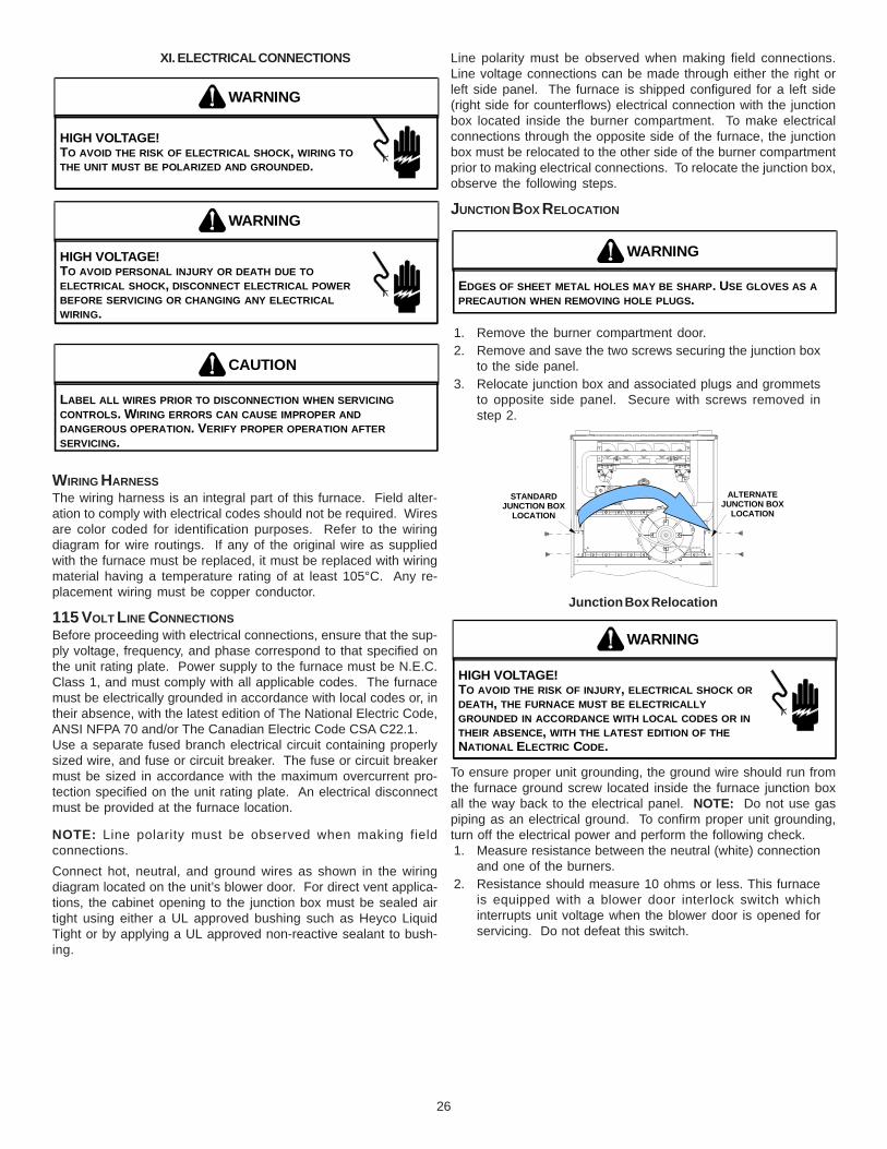
XI. Electrical Connections ................................................................................................................................................ 26WIRING HARNESS ............................................................................................................................................................ 26115 VOLT LINE CONNECTIONS ........................................................................................................................................... 26JUNCTION BOX RELOCATION .............................................................................................................................................. 2624 VOLT THERMOSTAT WIRING ........................................................................................................................................... 27GME95 FURNACE WITH 2-STAGE CONDENSER FIELD WIRING ................................................................................................ 27115 VOLT LINE CONNECTION OF ACCESSORIES (ELECTRONIC AIR CLEANER) ........................................................................... 2724 VOLT HUMIDIFIER ........................................................................................................................................................ 28
XII. Gas Supply and Piping .............................................................................................................................................. 28GENERAL ....................................................................................................................................................................... 28GAS PIPING CONNECTIONS ................................................................................................................................................ 28PROPANE GAS TANKS AND PIPING ...................................................................................................................................... 31
XIII. Circulating Air & Filters ............................................................................................................................................ 31DUCTWORK - AIR FLOW ................................................................................................................................................... 31CHECKING DUCT STATIC ................................................................................................................................................... 32BOTTOM RETURN AIR OPENING [UPFLOW MODELS] .............................................................................................................. 32FILTERS - READ THIS SECTION BEFORE INSTALLING THE RETURN AIR DUCTWORK ..................................................................... 33UPRIGHT INSTALLATIONS .................................................................................................................................................... 33HORIZONTAL INSTALLATIONS ................................................................................................................................................ 33
3
WARNING
GOODMAN WILL NOT BE RESPONSIBLE FOR ANY INJURY OR PROPERTYDAMAGE ARISING FROM IMPROPER SERVICE OR SERVICE PROCEDURES.IF YOU INSTALL OR PERFORM SERVICE ON THIS UNIT, YOU ASSUME RESPONSIBILITY FOR ANY PERSONAL INJURY OR PROPERY DAMAGE WHICHMAY RESULT. MANY JURISDICTIONS REQUIRE A LICENSE TO INSTALL ORSERVICE HEATING AND AIR CONDITIONING EQUIPMENT.
Table of ContentsXIV. Startup Procedure & Adjustment ............................................................................................................................. 33
XV. Normal Sequence of Operation ................................................................................................................................ 37POWER UP ..................................................................................................................................................................... 37HEATING MODE................................................................................................................................................................ 37(MODE DIP SWITCH IS SET TO “1 STG” POSITION) .............................................................................................................. 37(MODE DIP SWITCH IS SET TO “2 STG” POSITION) ............................................................................................................. 37COOLING MODE .............................................................................................................................................................. 38FAN ONLY MODE ............................................................................................................................................................. 38
XVI. Operational Checks .................................................................................................................................................. 38BURNER FLAME ............................................................................................................................................................... 38
XX. Before Leaving an Installation ................................................................................................................................. 41XXI. Repair & Replacement Parts ................................................................................................................................... 41
Troubleshooting Chart ...................................................................................................................................................... 42Blower Performance Data ............................................................................................................................................... 44Wiring Diagram ................................................................................................................................................................ 47Special Instructions for Products Installed ..................................................................................................................... 50
in the State of Massachusetts ....................................................................................................................................... 50
4
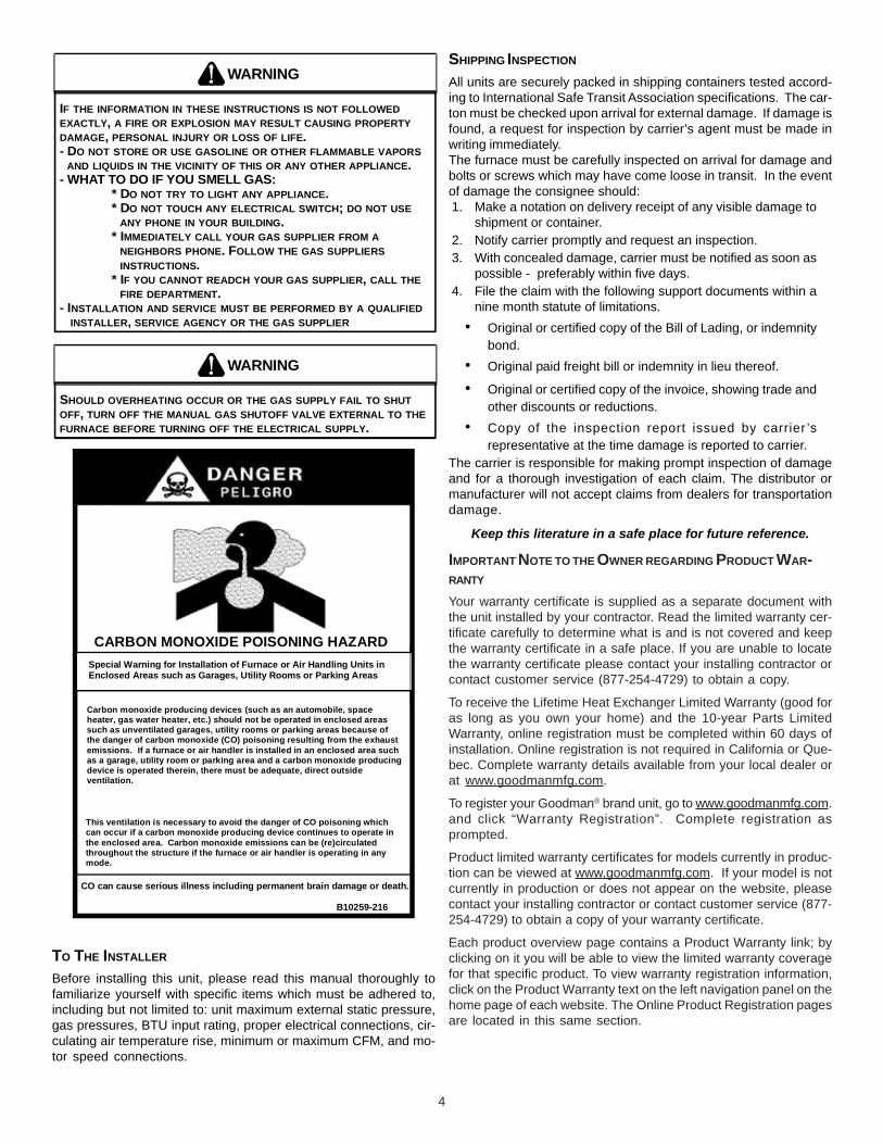
IF THE INFORMATION IN THESE INSTRUCTIONS IS NOT FOLLOWED EXACTLY, A FIRE OR EXPLOSION MAY RESULT CAUSING PROPERTY DAMAGE, PERSONAL INJURY OR LOSS OF LIFE.- DO NOT STORE OR USE GASOLINE OR OTHER FLAMMABLE VAPORS AND LIQUIDS IN THE VICINITY OF THIS OR ANY OTHER APPLIANCE.- WHAT TO DO IF YOU SMELL GAS:
* DO NOT TRY TO LIGHT ANY APPLIANCE.* DO NOT TOUCH ANY ELECTRICAL SWITCH; DO NOT USE
ANY PHONE IN YOUR BUILDING.* IMMEDIATELY CALL YOUR GAS SUPPLIER FROM A
NEIGHBORS PHONE. FOLLOW THE GAS SUPPLIERS INSTRUCTIONS.
* IF YOU CANNOT READCH YOUR GAS SUPPLIER, CALL THE FIRE DEPARTMENT.- INSTALLATION AND SERVICE MUST BE PERFORMED BY A QUALIFIED INSTALLER, SERVICE AGENCY OR THE GAS SUPPLIER
WARNING
SHOULD OVERHEATING OCCUR OR THE GAS SUPPLY FAIL TO SHUT OFF, TURN OFF THE MANUAL GAS SHUTOFF VALVE EXTERNAL TO THE FURNACE BEFORE TURNING OFF THE ELECTRICAL SUPPLY.
WARNING
CARBON MONOXIDE POISONING HAZARD
-
Special Warning for Installation of Furnace or Air Handling Units inEnclosed Areas such as Garages, Utility Rooms or Parking Areas
Carbon monoxide producing devices (such as an automobile, spaceheater, gas water heater, etc.) should not be operated in enclosed areassuch as unventilated garages, utility rooms or parking areas because ofthe danger of carbon monoxide (CO) poisoning resulting from the exhaustemissions. If a furnace or air handler is installed in an enclosed area suchas a garage, utility room or parking area and a carbon monoxide producingdevice is operated therein, there must be adequate, direct outsideventilation.
This ventilation is necessary to avoid the danger of CO poisoning whichcan occur if a carbon monoxide producing device continues to operate inthe enclosed area. Carbon monoxide emissions can be (re)circulatedthroughout the structure if the furnace or air handler is operating in anymode.
CO can cause serious illness including permanent brain damage or death.
B10259-216
TO THE INSTALLER
Before installing this unit, please read this manual thoroughly tofamiliarize yourself with specific items which must be adhered to,including but not limited to: unit maximum external static pressure,gas pressures, BTU input rating, proper electrical connections, cir-culating air temperature rise, minimum or maximum CFM, and mo-tor speed connections.
SHIPPING INSPECTION
All units are securely packed in shipping containers tested accord-ing to International Safe Transit Association specifications. The car-ton must be checked upon arrival for external damage. If damage isfound, a request for inspection by carrier’s agent must be made inwriting immediately.The furnace must be carefully inspected on arrival for damage andbolts or screws which may have come loose in transit. In the eventof damage the consignee should:1. Make a notation on delivery receipt of any visible damage to
shipment or container.2. Notify carrier promptly and request an inspection.3. With concealed damage, carrier must be notified as soon as
possible - preferably within five days.4. File the claim with the following support documents within a
nine month statute of limitations.• Original or certified copy of the Bill of Lading, or indemnity
bond.• Original paid freight bill or indemnity in lieu thereof.
• Original or certified copy of the invoice, showing trade andother discounts or reductions.
• Copy of the inspection report issued by carrier ’srepresentative at the time damage is reported to carrier.
The carrier is responsible for making prompt inspection of damageand for a thorough investigation of each claim. The distributor ormanufacturer will not accept claims from dealers for transportationdamage.
Keep this literature in a safe place for future reference.
IMPORTANT NOTE TO THE OWNER REGARDING PRODUCT WAR-RANTY
Your warranty certificate is supplied as a separate document withthe unit installed by your contractor. Read the limited warranty cer-tificate carefully to determine what is and is not covered and keepthe warranty certificate in a safe place. If you are unable to locatethe warranty certificate please contact your installing contractor orcontact customer service (877-254-4729) to obtain a copy.
To receive the Lifetime Heat Exchanger Limited Warranty (good foras long as you own your home) and the 10-year Parts LimitedWarranty, online registration must be completed within 60 days ofinstallation. Online registration is not required in California or Que-bec. Complete warranty details available from your local dealer orat www.goodmanmfg.com.
To register your Goodman® brand unit, go to www.goodmanmfg.com.and click “Warranty Registration”. Complete registration asprompted.
Product limited warranty certificates for models currently in produc-tion can be viewed at www.goodmanmfg.com. If your model is notcurrently in production or does not appear on the website, pleasecontact your installing contractor or contact customer service (877-254-4729) to obtain a copy of your warranty certificate.
Each product overview page contains a Product Warranty link; byclicking on it you will be able to view the limited warranty coveragefor that specific product. To view warranty registration information,click on the Product Warranty text on the left navigation panel on thehome page of each website. The Online Product Registration pagesare located in this same section.
5
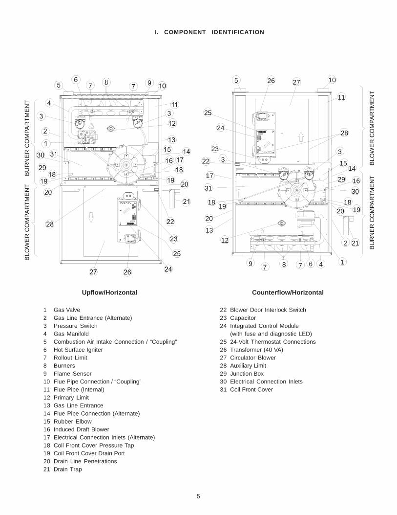
I. COMPONENT IDENTIFICATION
1 Gas Valve2 Gas Line Entrance (Alternate)3 Pressure Switch4 Gas Manifold5 Combustion Air Intake Connection / “Coupling”6 Hot Surface Igniter7 Rollout Limit8 Burners9 Flame Sensor10 Flue Pipe Connection / “Coupling”11 Flue Pipe (Internal)12 Primary Limit13 Gas Line Entrance14 Flue Pipe Connection (Alternate)15 Rubber Elbow16 Induced Draft Blower17 Electrical Connection Inlets (Alternate)18 Coil Front Cover Pressure Tap19 Coil Front Cover Drain Port20 Drain Line Penetrations21 Drain Trap
22 Blower Door Interlock Switch23 Capacitor24 Integrated Control Module
or shuffle your feet, do not touch ungrounded objects, etc.).If you come in contact with an ungrounded object, repeatstep 2 before touching control or wires.
4. Discharge your body to ground before removing a newcontrol from its container. Follow steps 1 through 3 ifinstalling the control on a furnace. Return any old or newcontrols to their containers before touching any ungroundedobject.
III. PRODUCT APPLICATION
This furnace is primarily designed for residential home-heatingapplications. It is NOT designed or certified for use in mobilehomes, trailers or recreational vehicles. This unit is NOT designedor certified for outdoor applications. The furnace must be installedindoors (i.e., attic space, crawl space, or garage area provided thegarage area is enclosed with an operating door).This furnace can be used in the following non-industrial commer-cial applications:
Schools, Office buildings, Churches, Retail storesNursing homes, Hotels/motels, Common or office areas
In such applications , the furnace must be installed with the follow-ing stipulations:
• It must be installed per the installation instructionsprovided and per local and national codes.
• It must be installed indoors in a building constructed onsite.
• It must be part of a ducted system and not used in a freeair delivery application.
• It must not be used as a “make-up” air unit.• It must be installed with two-pipe systems for combustion
air, especially if VOC’s or other contaminants are presentin the conditioned space.
• All other warranty exclusions and restrictions apply Thisfurnace is an ETL dual-certified appliance and isappropriate for use with natural or propane gas (NOTE: Ifusing propane, a propane conversion kit is required).
Dual certification means that the combustion air inlet pipe is op-tional and the furnace can be vented as a:
Non-direct vent (single pipe) central forced air furnace inwhich combustion air is taken from the installation areaor from air ducted from the outside or,Direct vent (dual pipe) central forced air furnace in whichall combustion air supplied directly to the furnace burnersthrough a special air intake system outlined in theseinstructions.
This furnace may be used as a construction site heater ONLY if thefollowing conditions are met:
• The vent system is permanently installed per theseinstallation instructions.
• A room thermostat is used to control the furnace. Fixedjumpers that provide continuous heating CANNOT beused.
• Return air ducts are provided and sealed to the furnace.• A return air temperature range between 60ºF (16ºC) and
80ºF (27ºC) is maintained.• Air filters are installed in the system and maintained
during construction, replaced as appropriate duringconstruction, and upon completion of construction arereplaced.
• The input rate and temperature rise are set per the furnacerating plate.
II. SAFETYPlease adhere to the following warnings and cautions when in-stalling, adjusting, altering, servicing, or operating the furnace.
TO PREVENT PERSONAL INJURY OR DEATH DUE TO IMPROPER INSTALLATION, ADJUSTMENT, ALTERATION, SERVICE OR MAINTENANCE, REFER TO THIS MANUAL. FOR ADDITIONAL ASSISTANCE OR INFORMATION, CONSULT A QUALIFIED INSTALLER, SERVICE AGENCY OR THE GAS SUPPLIER.
WARNING
THIS PRODUCT CONTAINS OR PRODUCES A CHEMICAL OR CHEMICALS WHICH MAY CAUSE SERIOUS ILLNESS OR DEATH AND WHICH ARE KNOWN TO THE STATE OF CALIFORNIA TO CAUSE CANCER, BIRTH DEFECTS OR OTHER REPRODUCTIVE HARM.
WARNING
HIGH VOLTAGE! TO AVOID PROPERTY DAMAGE, PERSONAL INJURY OR DEATH DUE TO ELECTRICAL SHOCK, THE FURNACE MUST BE LOCATED TO PROTECT THE ELECTRICAL COMPONENTS FROM WATER.
WARNING
DO NOT UTILIZE THE HEATING UNIT WITHOUT REASONABLE ROUTINE INSPECTION, MAINTENANCE AND SUPERVISION. IF THE UNIT IS IN A BUILDING THAT IS OR WILL BE VACANT, CARE SHOULD BE TAKEN TO ROUTINELY INSPECT, MAINTAIN AND MONITOR THE UNIT. IN THE EVENT THAT THE BUILDING MAY BE EXPOSED TO FREEZING TEMPERATURES AND WILL BE VACANT, DRAIN ALL WATER-BEARING PIPES, PROPERLY WINTERIZE THE BUILDING, AND TURN OFF ALL WATER SOURCES. IN THE EVENT THAT THE BUILDING IS EXPOSED TO FREEZING TEMPERATURES AND IS VACANT, ANY HYDRONIC COIL UNITS SHOULD ALSO BE DRAINED AND AN ALTERNATIVE HEAT SOURCES UTILIZED.
WARNING
ELECTROSTATIC DISCHARGE (ESD) PRECAUTIONS
NOTE: Discharge static electricity accumulated in the body beforetouching the unit. An electrostatic discharge can adversely affectelectrical components.Use the following precautions during furnace installation and ser-vicing to protect the integrated control module from damage. Byputting the furnace, the control, and the person at the same electro-static potential, these steps will help avoid exposing the integratedcontrol module to electrostatic discharge. This procedure is appli-cable to both installed and non-installed (ungrounded) furnaces.1. Disconnect all power to the furnace. Do not touch the
integrated control module or any wire connected to the controlprior to discharging your body’s electrostatic charge toground.
2. Firmly touch a clean, unpainted, metal surface of thefurnaces near the control. Any tools held in a person’s handduring grounding will be discharged.
3. Service integrated control module or connecting wiringfollowing the discharge process in step 2. Use caution notto recharge your body with static electricity; (i.e., do not move
7
The rated heating capacity of the furnace should be greater than orequal to the total heat loss of the area to be heated. The total heatloss should be calculated by an approved method or in accor-dance with “ASHRAE Guide” or “Manual J-Load Calculations” pub-lished by the Air Conditioning Contractors of America.
IV. LOCATION REQUIREMENTS & CONSIDERATIONS
GENERAL
TO PREVENT POSSIBLE EQUIPMENT DAMAGE, PROPERTY DAMAGE, PERSONAL INJURY OR DEATH, THE FOLLOWING BULLET POINTS MUST BE OBSERVED WHEN INSTALLING THE UNIT.
WARNING
Follow the instructions listed below when selecting a furnace loca-tion. Refer also to the guidelines provided in Section V, Combus-tion and Ventilation Air Requirements.
• Centrally locate the furnace with respect to the proposedor existing air distribution system.
• Ensure the temperature of the return air entering thefurnace is between 55°F and 100°F when the furnace isheating.
• Provide provisions for venting combustion productsoutdoors through a proper venting system. Specialconsideration should be given to vent/flue pipe routingand combustion air intake pipe when applicable. Referto Section IX, Vent/Flue Pipe and Combustion Air Pipe -Termination Locations for appropriate terminationlocations and to determine if the piping system fromfurnace to termination can be accomplished within theguidelines given. NOTE: The length of flue and/orcombustion air piping can be a limiting factor in thelocation of the furnace.
• Locate the furnace so condensate flows downwards tothe drain. Do not locate the furnace or its condensatedrainage system in any area subject to below freezingtemperatures without proper freeze protection. Refer toSection X, Condensate Drain Lines and Trap for furtherdetails.
• Ensure adequate combustion air is available for thefurnace. Improper or insufficient combustion air canexpose building occupants to gas combustion productsthat could include carbon monoxide. Refer to Section V,Combustion and Ventilation Air Requirements.
• Set the furnace on a level floor to enable propercondensate drainage. If the floor becomes wet or dampat times, place the furnace above the floor on a concretebase sized approximately 1-1/2" larger than the base ofthe furnace. Refer to the Section VII, HorizontalApplications and Considerations for leveling of horizontalfurnaces.
• Ensure upflow or horizontal furnaces are not installeddirectly on carpeting, or any other combustible material.The only combustible material allowed is wood.
• A special accessory subbase must be used for uprightcounterflow unit installations over any combustiblematerial (including wood). Refer to subbase instructionsfor installation details. (NOTE: A subbase will not berequired if an air conditioning coil is located beneath thefurnace between the supply air opening and thecombustible floor.
• 100% outside air is provided for combustion airrequirements during construction. Temporary ducting canbe used.NOTE: Do not connect the temporary duct directly to thefurnace. The duct must be sized according to theinstructions under Section V, Combustion and VentilationAir Requirements, Section 5.3.3.
• The furnace heat exchanger, components, duct system,air filters and evaporator coils are thoroughly cleanedfollowing final construction clean up.
• All furnace operating conditions (including ignition, inputrate, temperature rise and venting) are verified accordingto these installation instructions.
NOTE: The Commonwealth of Massachusetts requires that thefollowing additional requirements must also be met:
• Gas furnaces must be installed by a licensed plumber orgas fitter.
• A T-handle gas cock must be used.• If the unit is to be installed in an attic, the passageway to
and the service area around the unit must have flooring.
To ensure proper installation and operation, thoroughly read thismanual for specifics pertaining to the installation and applicationof this product.
POSSIBLE PROPERTY DAMAGE, PERSONAL INJURY OR DEATH DUE TO FIRE, EXPLOSION, SMOKE, SOOT, CONDENSATION, ELECTRICAL SHOCK OR CARBON MONOXIDE MAY RESULT FROM IMPROPER INSTALLATION, REPAIR, OPERATION, OR MAINTENANCE OF THIS PRODUCT.
WARNING
TO PREVENT PERSONAL INJURY, PROPERTY DAMAGE OR DEATH DUE TO FIRE, DO NOT INSTALL THIS FURNACE IN A MOBILE HOME, TRAILER OR RECREATIONAL VEHICLE.
WARNING
To ensure proper furnace operation, install, operate and maintainthe furnace in accordance with these installation and operationinstructions, all local building codes and ordinances. In their ab-sence, follow the latest edition of the National Fuel Gas Code(NFPA 54/ANSI Z223.1), and/or CAN/CSA B149.1-05.1-05 Installa-tion Codes, local plumbing or waste water codes, and other appli-cable codes.A copy of the National Fuel Gas Code (NFPA 54/ANSI Z223.1) canbe obtained from any of the following:
American National Standards Institute1430 BroadwayNew York, NY 10018
National Fire Protection Association1 Batterymarch ParkQuincy, MA 02269
CSA International8501 East Pleasant ValleyCleveland, OH 44131
A copy of the CAN/CSA B149.1-05.1-05 Installation Codes can alsobe obtained from:
A furnace installed in a confined space (i.e., a closet or utility room)must have two ventilation openings with a total minimum free areaof 0.25 square inches per 1,000 BTU/hr of furnace input rating.Refer to the Specification Sheet applicable to your model for mini-mum clearances to combustible surfaces. One of the ventilationopenings must be within 12 inches of the top; the other openingmust be within 12 inches of the bottom of the confined space. In atypical construction, the clearance between the door and door frameis usually adequate to satisfy this ventilation requirement.
FURNACE SUSPENSION
If suspending the furnace from rafters or joists, use 3/8" threadedrod and 2”x2”x1/8” angle iron as shown below. The length of rodwill depend on the application and the clearances necessary.
TILT OUTWARD TO ALLOW FORDOOR AND CIRCULATOR BLOWER
REMOVAL
3/8" DIAMETER THREADED ROD
(6 PLACES)
PROVIDE 8" MINMUM CLEARANCE BETWEENCENTER ROD AND FURNACE CABINET
TO ALLOW FOR CIRCULATOR BLOWER REMOVAL
ASSURE FURNACE IS LEVEL FROMEND TO END AND HAS A SLIGHTFORWARD TILT WITH THE FRONT
OF THE FURNACE 0"-3/4" BELOW THE BACK OF THE FURNACE
POSITION AS CLOSE AS POSSIBLETO BLOWER DECK TO ALLOW FOR CIRCULATOR BLOWER REMVOAL
2"X2"X1/8" ANGLE IRON(3 PLACES)
HOLD DOWN NUTS
SUPPORTNUTS
Suspended Furnace
EXISTING FURNACE REMOVAL
NOTE: When an existing furnace is removed from a venting systemserving other appliances, the venting system may be too large toproperly vent the remaining attached appliances.The following vent testing procedure is reproduced from the AmericanNational Standard/National Standard of Canada for Gas-Fired Cen-tral Furnaces ANSI Z21.47-Latest Edition, CSA-2.3b--Latest EditionSection 1.23.1.
The following steps shall be followed with each appliance connected to theventing system placed in operation, while any other appliances connectedto the venting system are not in operation:
a. Seal any unused openings in the venting system;
b. Inspect the venting system for proper size and horizontal pitch, asrequired by the National Fuel Gas Code, ANSI Z223.1 or the CSAB149.1-05.1-05 Installation Codes and these instructions. Deter-mine that there is no blockage or restriction, leakage, corrosion andother deficiencies which could cause an unsafe condition;
• Exposure to contaminated combustion air will result insafety and performance-related problems. Do not installthe furnace where the combustion air is exposed to thefollowing substances:
chlorinated waxes or cleanerschlorine-based swimming pool chemicalswater softening chemicalsdeicing salts or chemicalscarbon tetrachloridehalogen type refrigerantscleaning solutions (such as perchloroethylene)printing inkspaint removersvarnisheshydrochloric acidcements and gluesantistatic fabric softeners for clothes dryersand masonry acid washing materials
• Seal off a non-direct vent furnace if it is installed near anarea frequently contaminated by any of the abovesubstances. This protects the non-direct vent furnacefrom airborne contaminants. To ensure that theenclosed non-direct vent furnace has an adequate supplyof combustion air, vent from a nearby uncontaminatedroom or from outdoors. Refer to the Section V,Combustion and Ventilation Air Requirements for details.
• If the furnace is used in connection with a cooling unit,install the furnace upstream or in parallel with the coolingunit. Premature heat exchanger failure will result if thecooling unit is placed ahead of the furnace.For vertical (upflow or downflow) applications, theminimum cooling coil width shall not be less than furnacewidth minus 1”. Additionally, a coil installed above anupflow furnace or under a counterflow furnace may be thesame width as the furnace or may be one size larger thanthe furnace. Example: a “C” width coil may be installedwith a “B” width furnace.For upflow applications, the front of the coil and furnacemust face the same direction.
• If the furnace is installed in a residential garage, positionthe furnace so that the burners and ignition source arelocated not less than 18 inches (457 mm) above the floor.Protect the furnace from physical damage by vehicles.
• If the furnace is installed horizontally, the furnace accessdoors must be vertical so that the burners fire horizontallyinto the heat exchanger. Do not install the unit with theaccess doors on the “up/top” or “down/bottom” side ofthe furnace.
CLEARANCES AND ACCESSIBILITY
Installations must adhere to the clearances to combustible mate-rials to which this furnace has been design certified. The mini-mum clearance information for this furnace is provided on the unit’sclearance label. These clearances must be permanently main-tained. Clearances must also accommodate an installation’s gas,electrical, and drain trap and drain line connections. If the alternatevent/flue connection is used, additional clearance must be pro-vided to accommodate these connections. Refer to Section IX,Vent Flue Pipe and Combustion Air Pipe for details. NOTE: Inaddition to the required clearances to combustible materials, aminimum of 24 inches service clearance must be available in frontof the unit.
*NOTE: Please contact your distributor or our website for the applicable Specification Sheet referred to in this manual.
9
V. COMBUSTION & VENTILATION AIR REQUIREMENTS
WARNING
POSSIBLE PROPERTY DAMAGE PERSONAL INJURY OR DEATH MAY OCCUR IFTHE FURNACE IS NOT PROVIDED WITH ENOUGH FRESH AIR FOR PROPERCOMBUSTION AND VENTILATION OF FLUE GASES. MOST HOMES REQUIREOUTSIDE AIR BE SUPPLIED TO THE FURNACE AREA.
Improved construction and additional insulation in buildings havereduced heat loss by reducing air infiltration and escape arounddoors and windows. These changes have helped in reducingheating/cooling costs but have created a problem supplying com-bustion and ventilation air for gas fired and other fuel burning appli-ances. Appliances that pull air out of the house (clothes dryers,exhaust fans, fireplaces, etc.) increase the problem by starvingappliances for air.House depressurization can cause back drafting or improper com-bustion of gas-fired appliances, thereby exposing building occu-pants to gas combustion products that could include carbon mon-oxide.If this furnace is to be installed in the same space with other gasappliances, such as a water heater, ensure there is an adequatesupply of combustion and ventilation air for the other appliances.Refer to the latest edition of the National Fuel Gas Code NFPA 54/ANSI Z223.1 (Section 5.3), or CSA B149.1-05 Installation Codes(Sections 7.2, 7.3, or 7.4), or applicable provisions of the localbuilding codes for determining the combustion air requirementsfor the appliances.Most homes will require outside air be supplied to the furnace areaby means of ventilation grilles or ducts connecting directly to theoutdoors or spaces open to the outdoors such as attics or crawlspaces.The following information on air for combustion and ventilation is repro-duced from the National Fuel Gas Code NFPA 54/ANSI Z223.1 Section5.3.5.3.1 General:
(a) The provisions of 5.3 apply to gas utilization equipment installed inbuildings and which require air for combustion, ventilation and dilu-tion of flue gases from within the building. They do not apply to (1)direct vent equipment which is constructed and installed so that allair for combustion is obtained from the outside atmosphere and allflue gases are discharged to the outside atmosphere, or (2) enclosedfurnaces which incorporate an integral total enclosure and use onlyoutside air for combustion and dilution of flue gases.
(b) Equipment shall be installed in a location in which the facilities forventilation permit satisfactory combustion of gas, proper ventingand the maintenance of ambient temperature at safe limits undernormal conditions of use. Equipment shall be located so as not tointerfere with proper circulation of air. When normal infiltrationdoes not provide the necessary air, outside air shall be introduced.
(c) In addition to air needed for combustion, process air shall be pro-vided as required for: cooling of equipment or material, controllingdew point, heating, drying, oxidation or dilution, safety exhaust,odor control, and air for compressors.
(d) In addition to air needed for combustion, air shall be supplied forventilation, including all air required for comfort and proper workingconditions for personnel.
(e) While all forms of building construction cannot be covered in detail,air for combustion, ventilation and dilution of flue gases for gasutilization equipment vented by natural draft normally may be ob-tained by application of one of the methods covered in 5.3.3 and5.3.4.
c. In so far as practical, close all building doors and windows and alldoors between the space in which the appliance(s) connected to theventing system are located and other spaces of the building. Turn onclothes dryers and any appliance not connected to the venting sys-tem. Turn on any exhaust fans, such as range hoods and bathroomexhausts, so they shall operate at maximum speed. Do not operate asummer exhaust fan. Close fireplace dampers;
d. Follow the lighting instructions. Place the appliance being inspectedin operation. Adjust thermostat so appliance shall operate continu-ously;
e. Test for draft hood equipped spillage at the draft hood relief openingafter 5 minutes of main burner operation. Use the flame of a matchor candle;
f. After it has been determined that each appliance connected to theventing system properly vents when tested as outlined above, re-turn doors, windows, exhaust fans, fireplace dampers and any othergas burning appliance to their previous conditions of use;
g. If improper venting is observed during any of the above tests, thecommon venting system must be corrected.
Corrections must be in accordance with the latest edition of theNational Fuel Gas Code NFPA 54/ANSI Z223.1 and/or CSA B149.1-05.1-05 Installation Codes.If resizing is required on any portion of the venting system, use theappropriate table in Appendix G in the latest edition of the NationalFuel Gas Code ANSI Z223.1 and/or CSA B149.1-05.1-05 Installa-tion Codes.
THERMOSTAT LOCATIONThe thermostat should be placed approximately five feet from thefloor on a vibration-free, inside wall in an area having good aircirculation. Do not install the thermostat where it may be influ-enced by any of the following:
• Drafts, or dead spots behind doors, in corners, or undercabinets.
• Hot or cold air from registers.
• Radiant heat from the sun.
• Light fixtures or other appliances.
• Radiant heat from a fireplace.
• Concealed hot or cold water pipes, or chimneys.
• Unconditioned areas behind the thermostat, such as anoutside wall.
HOT
COLD
DRAFTS OR DEAD SPOTS-BEHIND DOORS -IN CORNERS -UNDER CABINETS
Thermostat InfluencesConsult the instructions packaged with the thermostat for mount-ing instructions and further precautions.
10
Furnace
WaterHeater
Outlet Air
Chimney or Gas Vent
NOTE: The inlet and outlet airopenings must each have a freearea of not less than one squareinch per 4000 BTU of thetotal input rating of all equipmentin the enclosure.
Inlet Air
Ventilation louvers forunheated crawl space
Alternateair inlet
Ventilation louvers(each end of attic)
Equipment Located in Confined Spaces; All Air from Outdoors—Inlet Air from Ventilated Crawl Space and Outlet Air to Ventilated
Attic. See 5.3.3-b2. When communicating with the outdoors through vertical ducts,
each opening shall have a minimum free area of 1 square inch per4,000 BTU per hour of total input rating of all equipment in theenclosure.
Furnace
WaterHeater
Outlet Air
Chimney or Gas Vent
NOTE: The inlet and outlet airopenings must each have a freearea of not less than one squareinch per 4000 BTU of thetotal input rating of all equipmentin the enclosure.
Inlet air duct[ends 1 ft (300 mm)above floor]
Ventilation louvers(each end of attic)
Equipment Located in Confined Spaces; All Air from OutdoorsThrough Ventilated Attic. See 5.3.3-b.
3. When communicating with the outdoors through horizontal ducts,each opening shall have a minimum free area of 1 square inch per2,000 BTU per hour of total input rating of all equipment in theenclosure.
FurnaceWaterHeater
Chimney or Gas Vent
NOTE: The air duct openingsmust have a free area of notless than one square inch per2000 BTU of the total inputrating of all equipment in theenclosure*.Outlet air duct
Inlet air duct
*If the appliance room is located against an outside wall and the air openings communicate directly with theoutdoors, each opening shall have a free area of not less than one square inch per 4,000 BTU per hour ofthe total input rating of all appliances in the enclosure.
Equipment Located in Confined Spaces; All Air from Outdoors.See 5.3.3-b.
(f) Air requirements for the operation of exhaust fans, kitchen ventila-tion systems, clothes dryers, and fireplaces shall be considered indetermining the adequacy of a space to provide combustion airrequirements.
5.3.2 Equipment Located in Unconfined Spaces: In unconfined spaces (see definition below) in buildings, infiltration may
be adequate to provide air for combustion ventilation and dilution offlue gases. However, in buildings of tight construction (for example,weather stripping, heavily insulated, caulked, vapor barrier, etc.), addi-tional air may need to be provided using the methods described in 5.3.3-b or 5.3.4.
Space, Unconfined. For purposes of this Code, a space whose volume is not less than 50
cubic feet per 1,000 BTU per hour of the aggregate input rating of allappliances installed in that space. Rooms communicating directly withthe space in which the appliances are installed through openings notfurnished with doors, are considered a part of the unconfined space.
5.3.3 Equipment Located in Confined Spaces:
(a) All Air from Inside the Building: The confined space shall be pro-vided with two permanent openings communicating directly withan additional room(s) of sufficient volume so that the combinedvolume of all spaces meets the criteria for an unconfined space. Thetotal input of all gas utilization equipment installed in the combinedspace shall be considered in making this determination. Each open-ing shall have a minimum free area of 1 square inch per 1,000 BTUper hour of the total input rating of all gas utilization equipment inthe confined space, but not less than 100 square inches. One open-ing shall be within 12 inches of the top and one within 12 inches ofthe bottom of the enclosure.
Furnace
WaterHeater
Opening
Chimney or Gas Vent
Opening
NOTE: Each opening must havea free area of not less than one square inch per 1000 BTU of the total input rating of all equip-ment in the enclosure, but notless than 100 square inches.
Equipment Located in Confined Spaces; All Air from InsideBuilding. See 5.3.3-a.
(b) All Air from Outdoors: The confined space shall be provided withtwo permanent openings, one commencing within 12 inches of thetop and one commencing within 12 inches of the bottom of theenclosure. The openings shall communicate directly, or by ducts,with the outdoors or spaces (crawl or attic) that freely communicatewith the outdoors.
1. When directly communicating with the outdoors, each openingshall have a minimum free area of 1 square inch per 4,000 BTUper hour of total input rating of all equipment in the enclosure.
11
4. When ducts are used, they shall be of the same cross-sectionalarea as the free area of the openings to which they connect. Theminimum dimension of rectangular air ducts shall not be lessthan 3 inches.
Furnace
WaterHeater
Opening
Chimney or Gas VentNOTE: The single opening must havea free area of not less than one square inch per 3000 BTU of the total input rating of all equip-ment in the enclosure, but not less than the sum of the areas of all ventconnectors in the confined space.
AlternateOpeningLocation
Equipment Located in Confined Spaces; All Air from Outdoors -Single Air Opening. See 5.3.3-b.
5. When directly communicating with the outdoors, the single open-ing shall have a minimum free area of 1 square inch per 3,000BTU per hour of total input rating of all equipment in the enclo-sure.
5.3.4 Specially Engineered Installations:
The requirements of 5.3.3 shall not necessarily govern when specialengineering, approved by the authority having jurisdiction, provides anadequate supply of air for combustion, ventilation, and dilution of fluegases.
5.3.5 Louvers and Grilles:
In calculating free area in 5.3.3, consideration shall be given to the block-ing effect of louvers, grilles or screens protecting openings. Screens usedshall not be smaller than 1/4 inch mesh. If the area through a design oflouver or grille is known, it should be used in calculating the size ofopening required to provide the free area specified. If the design and freearea is not known, it may be assumed that wood louvers will have 20-25percent free area and metal louvers and grilles will have 60-75 percentfree area. Louvers and grilles shall be fixed in the open position orinterlocked with the equipment so that they are opened automaticallyduring equipment operation.
5.3.6 Special Conditions Created by Mechanical Exhausting or Fire-places:
Operation of exhaust fans, ventilation systems, clothes dryers, or fire-places may create conditions requiring special attention to avoid unsat-isfactory operation of installed gas utilization equipment. Air fromInside Building. See 5.3.3-a.
VI. INSTALLATION POSITIONSThis furnace may be installed in an upright position or horizontalon either the left or right side panel. Do not install this furnace onits back. For upright upflow furnaces, return air ductwork may beattached to the side panel(s) and/or basepan. For horizontal up-flow furnaces, return air ductwork must be attached to the basepan.For both upright or horizontal counterflow furnaces, return duct-work must be attached to the basepan (top end of the blower com-partment). NOTE: Ductwork must never be attached to the back ofthe furnace. For upflow installations requiring 1,800 CFM or more,use either two side returns or a bottom return or a combination ofside and bottom. Contact your distributor for proper airflow require-ments and number of required ductwork connections. Refer to
“Recommended Installation Positions” figure for appropriate in-stallation positions, ductwork connections, and resulting airflowarrangements.
VII. HORIZONTAL APPLICATIONS & CONSIDERATIONS
GENERAL
Horizontal applications, in particular, may dictate many of theinstallation’s specifics such as airflow direction, ductwork connec-tions, flue and combustion air pipe connections, etc. The basicapplication of this furnace as a horizontal furnace differs only slightlyfrom an upright installation. When installing a furnace horizontally,additional consideration must be given to the following:
LOCATION
Horizontal FurnaceDRAIN TRAP AND LINES
In horizontal applications the condensate drain trap is secured tothe furnace side panel, suspending it below the furnace. A mini-mum clearance of 4 3/4 inches below the furnace must be pro-vided for the drain trap. Additionally, the appropriate downwardpiping slope must be maintained from the drain trap to the drainlocation. Refer to Section X, Condensate Drain Trap and Lines forfurther details. If the drain trap and drain line will be exposed totemperatures near or below freezing, adequate measures mustbe taken to prevent condensate from freezing.
LEVELING
Leveling ensures proper condensate drainage from the heat ex-changer and induced draft blower. For proper flue pipe drainage,the furnace must be level lengthwise from end to end. The furnaceshould also be level from back to front or have a slight tilt with theaccess doors downhill (approximately 3/4 inches) from the backpanel. The slight tilt allows the heat exchanger condensate, gen-erated in the recuperator coil, to flow forward to the recuperator coilfront cover.
ALTERNATE VENT/FLUE AND COMBUSTION AIR CONNECTIONS
In horizontal installations, provisions for alternate vent/flue pipingis available for upflow furnaces with left air discharge. Counterflowfurnaces include provisions for both alternate vent/flue and com-bustion air piping with right air discharge. These configurationsallow the flue and combustion air piping to be run vertically throughthe furnace. Refer to the “Recommended Installation Positions”figure for further detail. The standard piping connections may alsobe used in these positions. Refer to Section IX, Vent/Flue Pipeand Combustion Air Pipe for details concerning the conversion tothe alternate vent/flue air connections.
12
When using the horizontal alternate vent configuration, you mustuse the RF000142 vent drain kit. See following illustration.
AIR DISCHARGE
AIR DISCHARGE
AIR DISCHARGE
Bottom Return Duct
Connection
Bottom Return Duct
Connection
Bottom Return Duct
Connection
SideReturnDuct
Connection
SideReturnDuct
Connection
UPFLOWUPRIGHT
UPFLOW HORIZONTALRIGHT AIR DISCHARGE
UPFLOW HORIZONTALLEFT AIR DISCHARGE
ALTERNATE FLUEPIPE LOCATION
ALTERNATE FLUE PIPELOCATION
AIR DISCHARGE
AIR DISCHARGE
AIR DISCHARGE
Bottom Return Duct
Connection
Bottom Return Duct
Connection
Bottom Return Duct
Connection
COUNTERFLOWUPRIGHT
COUNTERFLOW HORIZONTALRIGHT AIR DISCHARGE
COUNTERFLOW HORIZONTALLEFT AIR DISCHARGE
ALTERNATE FLUE ANDCOMBUSTION AIR PIPELOCATIONS
ALTERNATE FLUE ANDCOMBUSTION AIR PIPELOCATIONS
Recommended Installation PositionsNOTE: Alternate “vertical” piping connections can not be used whenan upflow furnace is installed with supply air discharging to theright, or when a counterflow furnace is installed with supply airdischarging to the left. In either case, use the standard flue andcombustion air piping connections.
ALTERNATE ELECTRICAL AND GAS LINE CONNECTIONS
This furnace has provisions allowing for electrical and gas lineconnections through either side panel. In horizontal applicationsthe connections can be made either through the “top” or “bottom” ofthe furnace.
DRAIN PAN
A drain pan must be provided if the furnace is installed above aconditioned area. The drain pan must cover the entire area underthe furnace (and air conditioning coil if applicable).
FREEZE PROTECTION
Refer to Section VII, Horizontal Applications and Conditions - DrainTrap and Lines.
FURNACE SUSPENSION
If the furnace is installed in a crawl space it must be suspendedfrom the floor joist or supported by a concrete pad. Never install thefurnace on the ground or allow it to be exposed to water. Refer toSection IV, Location Requirements and Considerations - FurnaceSuspension for further details.
VIII. PROPANE GAS /HIGH ALTITUDE INSTALLATIONS
POSSIBLE PROPERTY DAMAGE, PERSONAL INJURY OR DEATH MAY OCCUR IF THE CORRECT CONVERSION KITS ARE NOT INSTALLED. THE APPROPRIATE KITS MUST BE APPLIED TO ENSURE SAFE AND PROPER FURNACE OPERATION. ALL CONVERSIONS MUST BE PERFORMED BY A QUALIFIED INSTALLER OR SERVICE AGENCY.
WARNING
This furnace is shipped from the factory configured for natural gasat standard altitude. Propane gas installations require an orificechange to compensate for the energy content difference betweennatural and propane gas.High altitude installations may require both a pressure switch andan orifice change. These changes are necessary to compensatefor the natural reduction in the density of both the gas fuel and thecombustion air at higher altitude.For installations above 7000 feet, please refer to your distributorfor required kit(s).
Altitude Gas Kit Orifice ManifoldPressure
PressureSwitch
0-7000
None
LPM-05*1
LPM-06*2
#43
#55
3.5" w.c.
10.0" w.c.
None
GMH95, GCH95, GCH9 GAS ORIFICE CHART
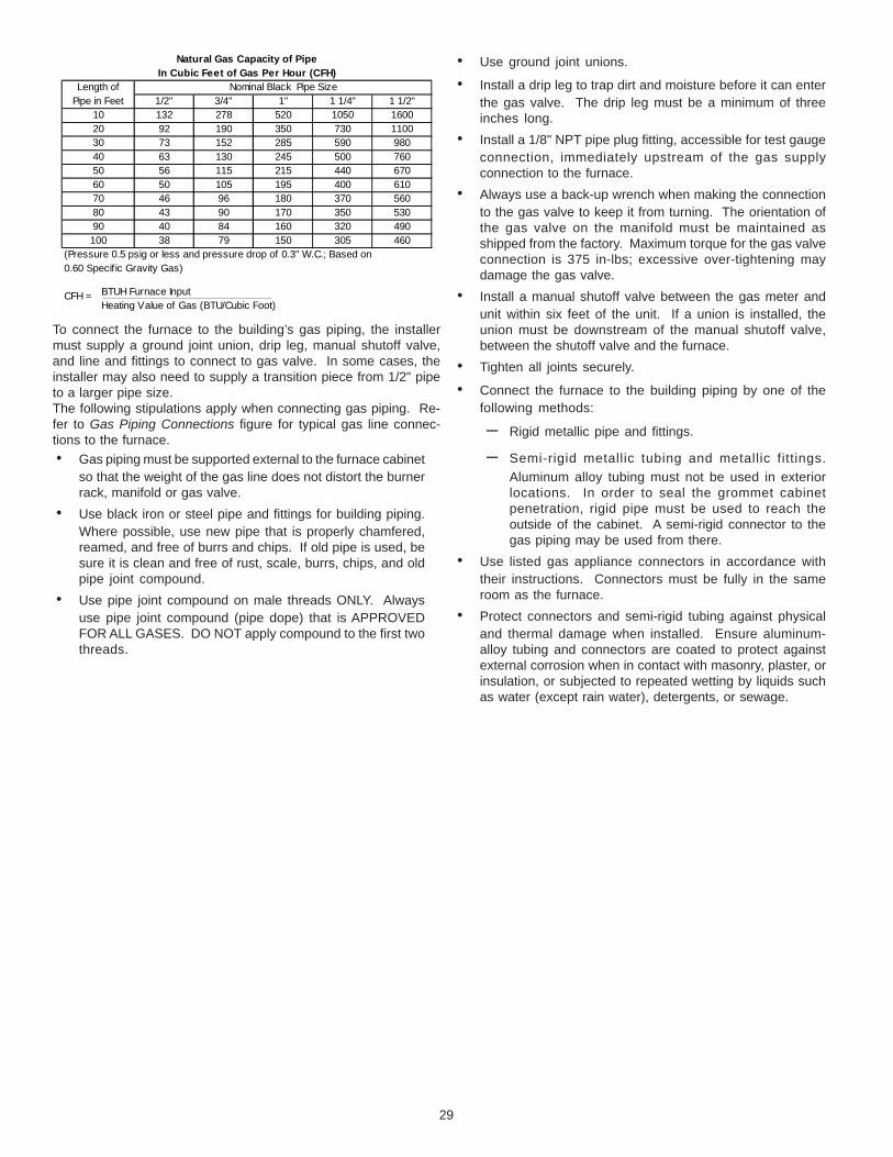
Natural
Propane
Altitude Gas Kit Orifice ManifoldPressure
PressureSwitch
1 LPM-05* supports White-Rodgers 2-stage valve only2 LPM-06* supports both Honeywell and White-Rodgers 2-stage valvesNOTE: In Canada, gas furnaces are certified to 4500 feet.
0-7000None
LPM-06*2
#45
#55
3.5" w.c.
10.0" w.c.None
GME95 GAS ORIFICE CHART
Natural
Propane
Contact the distributor for a tabular listing of appropriatemanufacturer’s kits for propane gas and/or high altitude installa-tions. The indicated kits must be used to insure safe and properfurnace operation. All conversions must be performed by a quali-fied installer, or service agency.
IX. VENT/FLUE PIPE & COMBUSTION AIR PIPE
GENERAL
FAILURE TO FOLLOW THESE INSTRUCTIONS CAN RESULT IN BODILY INJURY OR DEATH. CAREFULLY READ AND FOLLOW ALL INSTRUCTIONS GIVEN IN THIS SECTION.
WARNING
13
As an alternative to PVC pipe, primer, solvent cement, and fittings,ABS materials which are in compliance with the following specifi-cations may be used. Two-or-three-inch ABS Schedule 40 pipemust meet ASTM D1527 and, if used in Canada, must be CSAlisted. Solvent cement for ABS to ABS joints must meet ASTMD2235 and, if used in Canada, must be CSA listed. The solventcement for the PVC to ABS transition joint must meet ASTM D3138.Fittings must be DWV type fittings meeting ASTM D2661 and ASTMD3311 and, if used in Canada, must be CSA listed. Carefullyfollow the pipe manufacturers’ instructions for cutting, cleaning,and solvent cementing PVC and/or ABS.All 90° elbows must be medium radius (1/4 bend DWV) or longradius (Long sweep 1/4 bend DWV) types conforming to ASTMD3311. A medium radius (1/4 bend DWV) elbow measures 3 1/16” minimum from the plane of one opening to the centerline of theother opening for 2” diameter pipe, and 4 9/16” minimum for 3”pipe.
PROPER VENT/FLUE AND COMBUSTION AIR PIPING PRACTICES
Adhere to these instructions to ensure safe and proper furnaceperformance. The length, diameter, and number of elbows of thevent/flue pipe and combustion air pipe (when applicable) affectsthe performance of the furnace and must be carefully sized. Allpiping must be installed in accordance with local codes and theseinstructions.Piping must be adequately secured and supported to prohibit sag-ging, joint separation, and/or detachment from the furnace. Hori-zontal runs of vent/flue piping must be supported every three to fivefeet and must maintain a 1/4 inch per foot downward slope, backtowards the furnace, to properly return condensate to the furnace’sdrain system. Allowances should be made for minor expansionand contraction due to temperature variations. For this reason,particular care must be taken to secure piping when a long run isfollowed by a short offset of less than 40 inches.Precautions should be taken to prevent condensate from freez-ing inside the vent/flue pipe and/or at the vent/flue pipe termina-tion. It is our recommendation that all vent/flue piping exposed totemperatures below 35°F for extended periods of time should beinsulated with 1/2” thick closed cell foam. Also all vent/flue pipingexposed outdoors in excess of the terminations shown in thismanual (or in unheated areas) should be insulated with 1/2” thickclosed cell foam. Inspect piping for leaks prior to installing insu-lation.
TERMINATION LOCATIONS
NOTES: Refer to Section IV, Location Requirements andConsiderations for combustion air contaminant restrictions.
The following bullets and diagram describe the restrictions con-cerning the appropriate location of vent/flue pipe and combustionair intake pipe (when applicable) terminations. Refer to Non-Di-rect Vent (Single Pipe) Piping and Direct Vent (Dual Pipe) Pipinglocated in this section for specific details on termination construc-tion.
• All terminations (flue and/or intake) must be located atleast 12 inches above ground level or the anticipatedsnow level.
• Vent terminations (non-direct and direct vent) mustterminate at least 3 feet above any forced air inlet locatedwithin 10 feet.NOTE: This provision does not apply to the combustionair intake termination of a direct vent application.
UPON COMPLETION OF THE FURNACE INSTALLATION, CAREFULLY INSPECT THE ENTIRE FLUE SYSTEM BOTH INSIDE AND OUTSIDE OF THE FURNACE TO ASSURE IT IS PROPERLY SEALED. LEAKS IN THE FLUE SYSTEM CAN RESULT IN SERIOUS PERSONAL INJURY OR DEATH DUE TO EXPOSURE TO FLUE PRODUCTS, INCLUDING CARBON MONOXIDE.
WARNING
A condensing gas furnace achieves its high level of efficiency byextracting almost all of the heat from the products of combustionand cooling them to the point where condensation takes place.Because of the relatively low flue gas temperature and water con-densation requirements, PVC pipe is used as venting material.This furnace must not be connected to Type B, BW, or L vent or ventconnector, and must not be vented into any portion of a factory builtor masonry chimney except when used as a pathway for PVC asdescribed later in this section. Never common vent this appliancewith another appliance or use a vent which is used by a solid fuelappliance. Do not use commercially available “no hub connec-tors” other than those shipped with this product.It is the responsibility of the installer to follow the manufacturers’recommendations and to verify that all vent/flue piping and con-nectors are compatible with furnace flue products. Additionally, itis the responsibility of the installer to ensure that all piping andconnections possess adequate structural integrity and support toprevent flue pipe separation, shifting, or sagging during furnaceoperation.
DUAL CERTIFICATION: NON-DIRECT/DIRECT VENT
This furnace is dual certified and may be installed as a non-directvent (single pipe) or direct vent (dual pipe) appliance. A non-directvent installation requires only a vent/flue pipe, while a direct ventinstallation requires both a vent/flue pipe and a combustion airintake pipe. Refer to the appropriate section for details concerningpiping size, length, number of elbows, furnace connections, andterminations.
MATERIALS AND JOINING METHODS
TO AVOID BODILY INJURY, FIRE OR EXPLOSION, SOLVENT CEMENTS MUST BE KEPT AWAY FROM ALL IGNITION SOURCES (I.E., SPARKS, OPEN FLAMES, AND EXCESSIVE HEAT) AS THEY ARE COMBUSTIBLE LIQUIDS. AVOID BREATHING CEMENT VAPORS OR CONTACT WITH SKIN AND/OR EYES.
WARNING
Two- or three-inch nominal diameter PVC Schedule 40 pipe meet-ing ASTM D1785, PVC primer meeting ASTM F656, and PVC sol-vent cement meeting ASTM D2564 specifications must be used.Fittings must be DWV type fittings meeting ASTM D2665 and ASTMD3311. Carefully follow the manufacturer’s instructions for cutting,cleaning, and solvent cementing of PVC.The use of Schedule 40 PVC or ABS cellular core (Foam Core)plastic pipe is also acceptable as a flue/vent and intake pipe ma-terial. PVC primer meeting ASTM F656 and PVC solvent cementmeeting ASTM D2564 specifications must be used. Fittings mustbe DWV type fittings meeting ASTM D2665 and ASTM D3311. Care-fully follow the manufactures instructions for cutting, cleaning andsolvent cementing of PVC.For Canadian installations; all PVC pipe, fittings and joining mate-rials must be UL S636 listed.
14
v
V
X
DIRECT VENT TERMINAL CLEARANCES
1 In accordance with the current CSA B149.1, Natural Gas and Propane Installation Code.
2 In accordance with the current ANSI Z223.1/NFPA 54, National Fuel Gas Code.
† A vent shall not terminate directly above a sidewalk or paved driveway that is located between two single fanily dwellings and servesboth dwellings.
‡ Permitted only if veranda, porch, deck or balcony is fully open on a minimum of two sides beneath the floor.
* For clearances not specified in ANSI Z223.1/NFPA 54 or CSA B149.1, the following statement shall be included:
“Clearance in accordance wtih local installation codes and the requirements of the gas supplier and the manufacturer’s installationinstruction.”
Canadian Installations 1 U.S. Installations 2
I= Clearance to serviceregulator vent outlet.
3 ft. (91 cm). *
J= Clearance to nonmechanical air supply inlet to building or the combustion air inlet to any other appliance.
6 in. (15 cm) for appliances 10,000Btuh (3 kW), 12 in. (30 cm) for appliances > 10,000 Btuh (3kW) and 100,000 Btuh (30 kW), 36 in. (91 cm) for appliances > 100,000 Btuh (30 kW).
6 in. (15 cm) for appliances 10,000Btuh (3 kW), 9 in. (23 cm) for appliances > 10,000 Btuh (3kW) and 50,000 Btuh (15 kW), 12 in. (30 cm) for appliances > 50,000 Btuh (15 kW).
K= Clearance to a mechanicalair supply inlet.
6 ft. (1.83 m) 3 ft. (91 cm) above if within10 ft. (3 m) horizontally.
L= Clearance above paved sidewalk orpaved driveway located on public property.
7 ft. (2.13m) † *
M= Clearance under veranda, porch,deck or balcony.
12 in. (30 cm) ‡ *
Canadian Installations1 U.S. Installations 2
A= Clearance above grade,veranda, porch, deck orbalcony. (See 1.24.6-i(9)b.)
12 in. (30 cm) 12 in. (30 cm)
B= Clearance to window ordoor that may be opened.
6 in. (15 cm) for appliances10,000 Btuh (3 kW), 12 in. (30 cm) for appliances > 10,000 Btuh (3 kW) and 100,000 Btuh (30 kW), 36 in. (91 cm) for appliances > 100,000 Btuh (30 kW).
6 in. (15 cm) for appliances10,000 Btuh (3 kW), 9 in. (23 cm) for appliances > 10,000 Btuh (3 kW) and 50,000 Btuh (15 kW), 12 in. (30 cm) for appliances > 500,000 Btuh (15 kW).
C= Clearance to permanentlyclosed window.
* *
D= Vertical clearance to ventilated soffitlocated above the terminal within a horizontal distance of 2 feet (61 cm) from the center line of the terminal.
* *
E= Clearance to unventilated soffit. * *
F= Clearance to outside corner. * *
G= Clearance to inside corner. * *
H= Clearance to each side of centerline extended above meter/regulator assembly.
3 ft. (91 cm) within a height 15 ft.(4.5 m) above the meter/regulator assembly.
*
OTHER THAN DIRECT VENT TERMINAL CLEARANCES
1 In accordance with the current CSA B149.1, Natural Gas and Propane Installation Code.
2 In accordance with the current ANSI Z223.1/NFPA 54, National Fuel Gas Code.
† A vent shall not terminate directly above a sidewalk or paveable driveway that is located between two single family dwellings andserves both dwelling.
‡ Permitted only if veranda, porch, deck or balcony is fully open on a minimum of two sides beneath the floor.
* For clearances not specified in ANSI Z223.1/NFPA 54 or CSA B149.1, the following statement shall be included:
“Clearance in accordance wtih local installation codes and the requirements of the gas supplier and the manufacturer’s installationinstruction.”
Canadian Installations1 U.S. Installations2
I= Clearance to seviceregulator vent outlet.
3 ft. (91 cm). *
J= Clearance to nonmechanical air supply inlet to building or the combustion air inlet to any other appliance.
6 in. (15 cm) for appliances 10,000Btuh (3 kW), 12 in. (30 cm) for appliances > 10,000 Btuh (3kW) and 100,000 Btuh (30 kW), 36 in. (91 cm) for appliances > 100,000 Btuh (30 kW).
4 ft. (1.2 m) below or to side ofopening; 1 ft. (300 m) above opening.
K= Clearance to a mechanicalair supply inlet.
6 ft. (1.83 m) 3 ft. (91 cm) above if within10 ft. (3 m) horizontally.
L= Clearance above paved sidewalk orpaved driveway located on public property.
7 ft. (2.13m) † 7 ft. (2.13m)
M= Clearance under veranda, porch,deck or balcony.
12 in. (30 cm) ‡ *
Canadian Installations 1 U.S. Installations 2
A= Clearance above grade,veranda, porch, deck orbalcony. (See 1.24.6-i(9)b.)
12 in. (30 cm) 12 in. (30 cm)
B= Clearance to window ordoor that may be opened.
6 in. (15 cm) for appliances10,000 Btuh (3 kW), 12 in. (30 cm) for appliances > 10,000 Btuh (3 kW) and 100,000 Btuh (30 kW), 36 in. (91 cm) for appliances > 100,000 Btuh (30 kW).
4 ft. (1.2 m) below or to side ofopening; 1 ft. (300 m) above opening.
C= Clearance to permanentlyclosed window.
* *
D= Vertical clearance to ventilated soffitlocated above the terminal within a horizontal distance of 2 feet (61 cm) from the center line of the terminal.
* *
E= Clearance to unventilated soffit. * *
F= Clearance to outside corner. * *
G= Clearance to inside corner. * *
H= Clearance to each side of centerline extended above meter/regulator assembly.
3 ft. (91 cm) within a height 15 ft.(4.5 m) above the meter/regulator assembly.
*
15
• The vent termination of a non-direct vent application mustterminate at least 4 feet below, 4 feet horizontally from, or1 foot above any door, window, or gravity air inlet into anybuilding.
• The vent termination of a direct vent application mustterminate at least 12 inches from any opening throughwhich flue gases may enter a building (door, window, orgravity air inlet).
• The vent termination of vent pipe run vertically through aroof must terminate at least 12 inches above the roof line(or the anticipated snow level) and be at least 12 inchesfrom any vertical wall (including any anticipated snowbuild up).
• A vent termination shall not terminate over public walkwaysor over an area where condensate or vapor could createa nuisance or hazard or could be detrimental to theoperation of regulators, relief valves, or other equipment.
• The combustion air intake termination of a direct ventapplication should not terminate in an area which isfrequently dusty or dirty.
NOTE: In Canada, the Canadian Fuel Gas Code takes precedenceover the preceding termination restrictions.
CANADIAN VENTING REQUIREMENTS
In Canada, venting must conform to the requirements of the cur-rent CAN/CSA-B149.1-05 Installation Code. Use only CSA-listed,ULC-S636 compliant two- or three-inch diameter PVC or ABS pipe,solvent cement, and fittings throughout. The certified piping shouldbe clearly marked with the ULC Std “S636” on the pipe and fittings.Carefully follow the pipe manufacturers’ instructions for cutting,cleaning, and solvent cementing PVC and/or ABS.The vent can be run through an existing unused chimney providedthe space between the vent pipe and the chimney is insulated andclosed with a weather-tight, corrosion-resistant flashing.
STANDARD FURNACE CONNECTIONS
It is the responsibility of the installer to ensure that the pipingconnections to the furnace are secure, airtight, and adequatelysupported.As shipped, attachment “couplings” for vent/flue and combustionair intake pipe connections are provided on the furnace’s top cover(upflow) or basepan (counterflow). To use the standard connec-tions, field supplied vent/flue pipe and combustion air intake pipe(when applicable) should be secured directly to the furnace atthese locations.
VENT/FLUE PIPE
Vent/flue pipe can be secured to the vent/flue coupling using therubber coupling and worm gear hose clamps provided with thisfurnace (see “Standard Connections” figure). The rubber couplingallows separation of the vent/flue pipe from the furnace duringservicing. Combustion Air and Vent piping should be routed in amanner to avoid contact with refrigerant lines, metering devices,condensate drain lines, etc. If necessary, clearances may beincreased by utilizing two 45 deg. Long-Sweep Elbows and creat-ing an “S” joint to provide additional space at connection loca-tions. This joint can be rotated on the fitting to establish maxi-mum clearance between refrigerant lines, metering devices, andcondensate drain lines, etc. This joint is the equivalent of one 90deg. elbow when considering elbow count.
45 DEGREELONG-SWEEP
ELBOWS
VENT
Increased Clearance Configuration
NOTE: Do not use other commercially available “no hub connec-tors” due to possible material conflicts. The vent/flue pipe canalso be secured using a PVC or ABS elbow or coupling using theappropriate glue (see Section IX, Materials and Joining Methods).
NOTE: For non-direct vent installations, a minimum of one 90°elbow should be installed on the combustion air intake couplingto guard against inadvertent blockage.COMBUSTION AIR PIPEDIRECT VENT INSTALLATIONS
On upflow units secure the combustion air intake pipe directly tothe air intake coupling. On counterflow units secure the combus-tion air intake pipe to the air intake coupling using the rubber cou-pling and worm gear hose clamps provided with the unit. Thecounterflow rubber coupling allows service removal of air intakepiping internal to the furnace blower compartment. NOTE: Be-cause of probable material conflicts, do not use other commer-cially available “no hub connectors”. The combustion air intakepipe can also be secured directly to the counterflow unit air intakepipe coupling.NON-DIRECT VENT INSTALLATIONS
A minimum of one 90° elbow should be installed on the combus-tion air intake “coupling” to guard against inadvertent blockage.
RUBBERCOUPLING
WITH WORMGEAR CLAMPS
RUBBERCOUPLINGSWITH WORM
GEAR CLAMPS
COMBUSTIONAIR PIPE
(DIRECT VENT ONLY)
COMBUSTIONAIR PIPE
(DIRECT VENT ONLY)VENT/FLUE
PIPE
VENT/FLUEPIPE
90º PVCELBOW
(NON-DIRECT VENT)
90º PVCELBOW
(NON-DIRECT VENT)
STANDARD CONNECTIONS
OROR
UPFLOW COUNTERFLOW
16
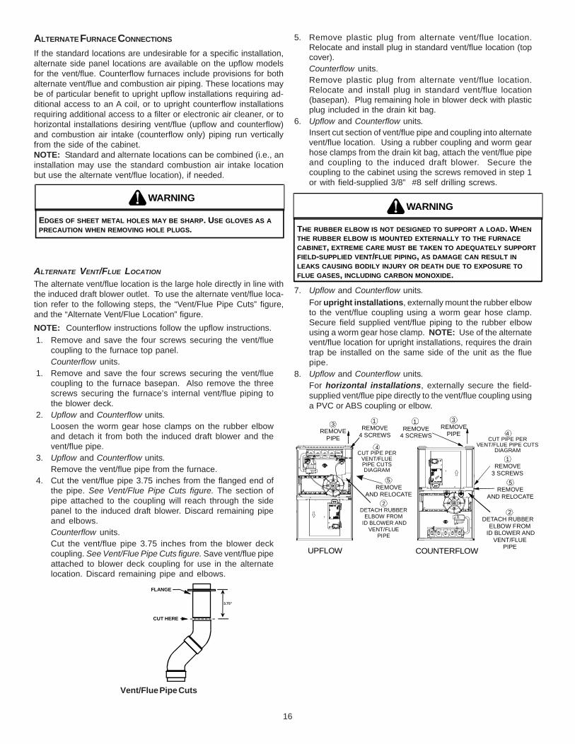
ALTERNATE FURNACE CONNECTIONS
If the standard locations are undesirable for a specific installation,alternate side panel locations are available on the upflow modelsfor the vent/flue. Counterflow furnaces include provisions for bothalternate vent/flue and combustion air piping. These locations maybe of particular benefit to upright upflow installations requiring ad-ditional access to an A coil, or to upright counterflow installationsrequiring additional access to a filter or electronic air cleaner, or tohorizontal installations desiring vent/flue (upflow and counterflow)and combustion air intake (counterflow only) piping run verticallyfrom the side of the cabinet.NOTE: Standard and alternate locations can be combined (i.e., aninstallation may use the standard combustion air intake locationbut use the alternate vent/flue location), if needed.
EDGES OF SHEET METAL HOLES MAY BE SHARP. USE GLOVES AS A PRECAUTION WHEN REMOVING HOLE PLUGS.
WARNING
ALTERNATE VENT/FLUE LOCATION
The alternate vent/flue location is the large hole directly in line withthe induced draft blower outlet. To use the alternate vent/flue loca-tion refer to the following steps, the “Vent/Flue Pipe Cuts” figure,and the “Alternate Vent/Flue Location” figure.NOTE: Counterflow instructions follow the upflow instructions.1. Remove and save the four screws securing the vent/flue
coupling to the furnace top panel.Counterflow units.
1. Remove and save the four screws securing the vent/fluecoupling to the furnace basepan. Also remove the threescrews securing the furnace’s internal vent/flue piping tothe blower deck.
2. Upflow and Counterflow units.Loosen the worm gear hose clamps on the rubber elbowand detach it from both the induced draft blower and thevent/flue pipe.
3. Upflow and Counterflow units.Remove the vent/flue pipe from the furnace.
4. Cut the vent/flue pipe 3.75 inches from the flanged end ofthe pipe. See Vent/Flue Pipe Cuts figure. The section ofpipe attached to the coupling will reach through the sidepanel to the induced draft blower. Discard remaining pipeand elbows.Counterflow units.Cut the vent/flue pipe 3.75 inches from the blower deckcoupling. See Vent/Flue Pipe Cuts figure. Save vent/flue pipeattached to blower deck coupling for use in the alternatelocation. Discard remaining pipe and elbows.
FLANGE
CUT HERE
3.75"
Vent/Flue Pipe Cuts
5. Remove plastic plug from alternate vent/flue location.Relocate and install plug in standard vent/flue location (topcover).Counterflow units.Remove plastic plug from alternate vent/flue location.Relocate and install plug in standard vent/flue location(basepan). Plug remaining hole in blower deck with plasticplug included in the drain kit bag.
6. Upflow and Counterflow units.Insert cut section of vent/flue pipe and coupling into alternatevent/flue location. Using a rubber coupling and worm gearhose clamps from the drain kit bag, attach the vent/flue pipeand coupling to the induced draft blower. Secure thecoupling to the cabinet using the screws removed in step 1or with field-supplied 3/8” #8 self drilling screws.
THE RUBBER ELBOW IS NOT DESIGNED TO SUPPORT A LOAD. WHEN THE RUBBER ELBOW IS MOUNTED EXTERNALLY TO THE FURNACE CABINET, EXTREME CARE MUST BE TAKEN TO ADEQUATELY SUPPORT FIELD-SUPPLIED VENT/FLUE PIPING, AS DAMAGE CAN RESULT IN LEAKS CAUSING BODILY INJURY OR DEATH DUE TO EXPOSURE TO FLUE GASES, INCLUDING CARBON MONOXIDE.
WARNING
7. Upflow and Counterflow units.For upright installations, externally mount the rubber elbowto the vent/flue coupling using a worm gear hose clamp.Secure field supplied vent/flue piping to the rubber elbowusing a worm gear hose clamp. NOTE: Use of the alternatevent/flue location for upright installations, requires the draintrap be installed on the same side of the unit as the fluepipe.
8. Upflow and Counterflow units.For horizontal installations, externally secure the field-supplied vent/flue pipe directly to the vent/flue coupling usinga PVC or ABS coupling or elbow.
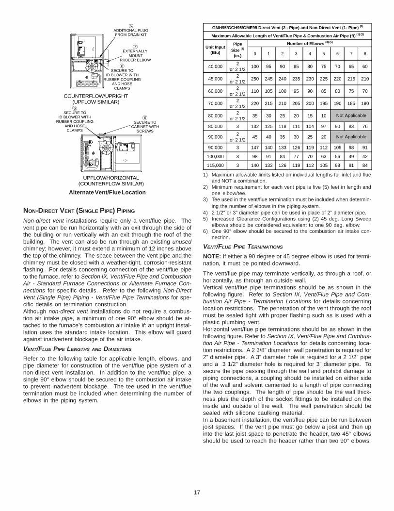
GMH95/GCH95/GME95 Direct Vent (2 - Pipe) and Non-Direct Vent (1- Pipe) (6)
Maximum Allowable Length of Vent/Flue Pipe & Combustion Air Pipe (ft) (1) (2)
Unit Input (Btu)
PipeSize (4)
(in.)
Number of Elbows (3) (5)
1) Maximum allowable limits listed on individual lengths for inlet and flueand NOT a combination.
2) Minimum requirement for each vent pipe is five (5) feet in length andone elbow/tee.
3) Tee used in the vent/flue termination must be included when determin-ing the number of elbows in the piping system.
4) 2 1/2” or 3” diameter pipe can be used in place of 2” diameter pipe.5) Increased Clearance Configurations using (2) 45 deg. Long Sweep
elbows should be considered equivalent to one 90 deg. elbow.6) One 90° elbow should be secured to the combustion air intake con-
nection.
VENT/FLUE PIPE TERMINATIONS
NOTE: If either a 90 degree or 45 degree elbow is used for termi-nation, it must be pointed downward.
The vent/flue pipe may terminate vertically, as through a roof, orhorizontally, as through an outside wall.Vertical vent/flue pipe terminations should be as shown in thefollowing figure. Refer to Section IX, Vent/Flue Pipe and Com-bustion Air Pipe - Termination Locations for details concerninglocation restrictions. The penetration of the vent through the roofmust be sealed tight with proper flashing such as is used with aplastic plumbing vent.Horizontal vent/flue pipe terminations should be as shown in thefollowing figure. Refer to Section IX, Vent/Flue Pipe and Combus-tion Air Pipe - Termination Locations for details concerning loca-tion restrictions. A 2 3/8” diameter wall penetration is required for2” diameter pipe. A 3” diameter hole is required for a 2 1/2” pipeand a 3 1/2” diameter hole is required for 3” diameter pipe. Tosecure the pipe passing through the wall and prohibit damage topiping connections, a coupling should be installed on either sideof the wall and solvent cemented to a length of pipe connectingthe two couplings. The length of pipe should be the wall thick-ness plus the depth of the socket fittings to be installed on theinside and outside of the wall. The wall penetration should besealed with silicone caulking material.In a basement installation, the vent/flue pipe can be run betweenjoist spaces. If the vent pipe must go below a joist and then upinto the last joist space to penetrate the header, two 45° elbowsshould be used to reach the header rather than two 90° elbows.
5ADDITIONAL PLUGFROM DRAIN KIT
7EXTERNALLY
MOUNTRUBBER ELBOW6
SECURE TOID BLOWER WITH
RUBBER COUPLINGAND HOSE
CLAMPS
COUNTERFLOW/UPRIGHT(UPFLOW SIMILAR)
UPFLOW/HORIZONTAL(COUNTERFLOW SIMILAR)
6SECURE TO
ID BLOWER WITHRUBBER COUPLING
AND HOSECLAMPS
6SECURE TO
CABINET WITHSCREWS
Alternate Vent/Flue Location
NON-DIRECT VENT (SINGLE PIPE) PIPING
Non-direct vent installations require only a vent/flue pipe. Thevent pipe can be run horizontally with an exit through the side ofthe building or run vertically with an exit through the roof of thebuilding. The vent can also be run through an existing unusedchimney; however, it must extend a minimum of 12 inches abovethe top of the chimney. The space between the vent pipe and thechimney must be closed with a weather-tight, corrosion-resistantflashing. For details concerning connection of the vent/flue pipeto the furnace, refer to Section IX, Vent/Flue Pipe and CombustionAir - Standard Furnace Connections or Alternate Furnace Con-nections for specific details. Refer to the following Non-DirectVent (Single Pipe) Piping - Vent/Flue Pipe Terminations for spe-cific details on termination construction.Although non-direct vent installations do not require a combus-tion air intake pipe, a minimum of one 90° elbow should be at-tached to the furnace’s combustion air intake if: an upright instal-lation uses the standard intake location. This elbow will guardagainst inadvertent blockage of the air intake.
VENT/FLUE PIPE LENGTHS AND DIAMETERS
Refer to the following table for applicable length, elbows, andpipe diameter for construction of the vent/flue pipe system of anon-direct vent installation. In addition to the vent/flue pipe, asingle 90° elbow should be secured to the combustion air intaketo prevent inadvertent blockage. The tee used in the vent/fluetermination must be included when determining the number ofelbows in the piping system.
The inlet air screens provided in the installation instruction packetare available for the installer to use in the inlet of the combustionair pipe to prevent animals from building nests in the combustionair pipe. Installation of screens, while strongly recommended, isnot required and will not affect performance of the unit.
Direct vent installations require both a combustion air intake and avent/flue pipe. The pipes may be run horizontally and exit throughthe side of the building or run vertically and exit through the roof ofthe building. The pipes may be run through an existing unusedchimney; however, they must extend a minimum of 12 inchesabove the top of the chimney. The space between the pipes andthe chimney must be closed with a weather tight, corrosion resis-tant flashing. Both the combustion air intake and a vent/flue pipeterminations must be in the same atmospheric pressure zone.For details concerning connection of pipes to the furnace, refer tothe Section IX, Vent/Flue Pipe and Combustion Pipe - StandardFurnace Connections or Alternate Furnace Connections.
VENT/FLUE AND COMBUSTION AIR PIPE LENGTHS AND DIAMETERS
Refer to the following table for applicable length, elbows, and pipediameter for construction of the vent/flue and combustion air intakepipe systems of a direct vent (dual pipe) installation. The numberof elbows tabulated represents the number of elbows and/or teesin each (Vent/Flue & Combustion Air Intake) pipe. Elbows and/ortees used in the terminations must be included when determiningthe number of elbows in the piping systems.If the combustion air intake pipe is to be installed above a finishedceiling or other area where dripping of condensate will be objec-tionable, insulation of the combustion air pipe may be required.Use 1/2” thick closed cell foam insulation such as Armaflex orInsultube where required.
VENT/FLUE AND COMBUSTION AIR PIPE TERMINATIONS
The vent/flue and combustion air pipes may terminate vertically, asthrough a roof, or horizontally, as through an outside wall.Vertical pipe terminations should be as shown in the followingfigure. Refer to Section IX, Vent/Flue Pipe and Combustion Pipe -Termination Locations for details concerning location restrictions.The penetrations through the roof must be sealed tight with properflashing such as is used with a plastic plumbing vent.
VENT/FLUE
COMBUSTIONAIR INTAKE
SCREENOPTIONAL
12" MIN. TO ROOFOR HIGHEST ANTICIPATED
SNOW LEVEL
12" MIN.
TEE (OPTIONAL)
Vertical Terminations (Dual Pipe)Horizontal terminations should be as shown in the following fig-ure. Refer to Section IX, Vent/Flue Pipe and Combustion Pipe -Termination Location for location restrictions. A 2 3/8” diameterwall penetration is required for 2” diameter pipe. A 3” diameter holeis required for a 2 1/2” pipe and a 3 1/2” diameter hole is requiredfor 3” diameter pipe. To secure the pipe passing through the walland prohibit damage to piping connections, a coupling should beinstalled on either side of the wall and solvent cemented to a pipeconnecting the two couplings. The pipe length should be the wallthickness plus the depth of the socket fittings to be installed on theinside and outside of the wall. The wall penetration should besealed with silicone caulking material.
19
SCREEN(OPTIONAL)
90º or 45°MEDIUM RADIUS
ELBOWS
12" MIN
3" MIN24" MAX
3" MIN24" MAX
12" MIN. ABOVEHIGHEST ANTICIPATED
SNOW LEVEL
12" MIN. ABOVEHIGHEST ANTICIPATED
SNOW LEVEL
Standard Horizontal Terminations (Dual Pipe)
_______________
24" MAX3" MIN
SCREEN(OPTIONAL)
24" MAX
AIRINTAKE
90°MEDIUM RADIUSELBOW
12" MIN. ABOVEHIGHEST ANTICIPATED
SNOW LEVEL
Alternate Horizontal Vent Termination (Dual Pipe)
SUPPORTSTRAPS
VENT/FLUETEE (OPTIONAL)
12" MIN. ABOVEHIGHEST ANTICIPATED
SNOW LEVEL
12" MIN. ABOVEHIGHEST ANTICIPATED
SNOW LEVEL
90° or 45°MEDIUM RADIUS
ELBOWS
SCREEN(OPTIONAL)
COMBUSTIONAIR INTAKE
12" MIN
3" MIN24" MAX
Standard Horizontal Terminations Above Anticipated SnowLevel (Dual Pipe)
In a basement installation, the pipes may be run between the joistspaces. If the pipes must go below the joist and then up into thelast joist space to penetrate the header, two 45° elbows should beused to reach the header rather than two 90° elbows.
VENT/INTAKE TERMINATIONS FOR INSTALLATION OF MULTIPLEDIRECT VENT FURNACES
If more than one direct vent furnace is to be installed verticallythrough a common roof top, maintain the same minimum clear-ances between the exhaust vent and air intake terminations ofadjacent units as with the exhaust vent and air intake terminationsof a single unit.If more than one direct vent furnace is to be installed horizontallythrough a common side wall, maintain the clearances as in thefollowing figure. Always terminate all exhaust vent outlets at thesame elevation and always terminate all air intakes at the sameelevation.
Vents
24" Max.3" Min.
12" Min.Screen(Optional)
24" Max.
AirIntakes
90° MediumRadiusElbows
24" Max.3" Min.
3" Min.
12" MIN. ABOVEHIGHEST ANTICIPATED
SNOW LEVEL
Horizontal Venting Of Multiple Units
CONCENTRIC VENT TERMINATION
Refer to the directions provided with the Concentric Vent Kit (DCVK)for installation specifications.
20
SIDE WALL VENT KIT
This kit is to be used with 2” or 3” direct vent systems. The vent kitmust terminate outside the structure and may be installed with theintake and exhaust pipes located side-by-side or with one pipeabove the other. This kit is NOT intended for use with single pipe(indirect vent) installations.Refer to the directions furnished with the Side Wall Vent Kit (p/n0170K00000S) for installation specifications.
X. CONDENSATE DRAIN LINES & DRAIN TRAPA condensing gas furnace achieves its high level of efficiency byextracting almost all of the heat from the products of combustionand cooling them to the point where condensation takes place.The condensate which is generated must be piped to an appropri-ate drain location.In upright installations, the furnace’s drain hoses may exit eitherthe right or left side of the furnace. NOTE: If the alternate vent/flueoutlet is utilized in an upright installation, the drain trap and drainconnections must be located on the same side as the alternatevent/flue outlet.In horizontal installations, the drain hoses will exit through thebottom (down side) of the unit with the drain trap suspended be-neath the furnace. The field-supplied drain system must be inaccordance with all local codes and the instructions in the follow-ing sections.
Follow the bullets listed below when installing the drain system.Refer to the following sections for specific details concerning fur-nace drain trap installation and drain hose hook ups.
• The drain trap supplied with the furnace must be used.• The drain line between furnace and drain location must
be constructed of 3/4” PVC.• The drain line between furnace and drain location must
maintain a 1/4 inch per foot downward slope towardthe drain.
• Do not trap the drain line in any other location than atthe drain trap supplied with the furnace.
• Do not route the drain line outside where it may freeze.• If the drain line is routed through an area which may
see temperatures near or below freezing, precautionsmust be taken to prevent condensate from freezingwithin the drain line.
• If an air conditioning coil is installed with the furnace, acommon drain may be used. An open tee must beinstalled in the drain line, near the cooling coil, torelieve positive air pressure from the coil’s plenum.This is necessary to prohibit any interference with thefunction of the furnace’s drain trap.
NOTE: In vertical installations, air conditioning coil condensate maydrain into the furnace trap as long as there is a trap between the coiland the furnace trap and the drain pipe is not terminating below thewater level of the furnace trap.
21
STANDARD RIGHT OR LEFT SIDE DRAIN HOSE CONNECTIONS
All installations positions require the use of the drain trap, hoses,tubes, and clamps. The following quantity of hoses, tubes, andhose clamps are provided with the unit.
DRAIN TRAPQTY: 1
GREENHOSE CLAMPSQTY: 3 SILVER
HOSE CLAMPQTY: 1
TUBE 2QTY: 2
TUBE 1QTY: 1
HOSE BQTY: 1
HOSE AQTY: 1
REDHOSE CLAMPQTY: 1
Hose and Tube IdentificationIn a upright installation drain hoses are connected to drain portson the rubber elbow and the recuperator coil front cover. The drainlines are then routed through the right side panel and into the draintrap secured to the outside of the cabinet.NOTE: Refer to Alternate Vent/Flue Hose Connections for uprightinstallations using an alternate vent/flue outlet.
1. Remove the rubber plug from the right side of the front coverdrain port.
2. Secure Hose A to front cover drain port with a red hoseclamp. Route hose to rear side panel grommet hole.
3. Cut and remove 1/4 inch from the end of the drain port onthe rubber elbow.
4. Insert Tube 1 into rubber elbow drain port and secure withsilver hose clamp. Angle tube outward toward front offurnace.
5. Cut 17 3/4 inches from the long end of Hose B and discard.Secure the remaining hose to Tube 1 with a green hoseclamp. Route the other end of Hose B to front right sidepanel grommet hole.
For details concerning mounting of the drain trap, refer to VerticalDrain Trap Mounting.
6. Insert short end of each of tube 2 through side panelgrommet holes. Secure tubes to hoses A and B with greenhose clamps. Ensure hoses and tubes maintain adownward slope for proper drainage and that they are notkinked or binding.
DRAINTRAP
FRONTCOVER
DRAIN PORT
TUBE(S) 2
GREENHOSE
CLAMPS(3 PLACES)
RIGHT SIDEPANEL
RUBBER ELBOW DRAIN PORT
TUBE 1
SIDE PANELGROMMET
HOLES
HOSEB
HOSE A
RUBBERELBOW
RED HOSECLAMP
SILVER HOSE CLAMP
22
RUBBER ELBOW(EXTERNALLY
MOUNTED)
TUBE 1
GREEN HOSECLAMPS
(3 PLACES)
HOSE B
TUBE(S) 2DRAIN TRAP
HOSE A
FRONTCOVERDRAINPORT
RUBBERELBOW
DRAIN PORT
RED HOSECLAMP
SILVER HOSE CLAMP
ALTERNATE VENT/FLUE DRAIN HOSE CONNECTIONS
Upright installations using the alternate vent/flue outlet will require“right-side only” drain hoses to be connected as follows. Refer toVent/Flue Pipe and Combustion Air Pipe for details on alternatevent/flue pipe connection.1. Remove the rubber plug from the right-side drain port on
the front cover . Save for use in step 3.2. Secure Hose A to front cover drain port with a red hose
clamp. Route hose to rear right side panel grommet hole.3. Remove grommet from front right-side panel drain hole.
Seal hole in grommet with large end of plug. Reinstallgrommet and plug into side panel drain hole.
4. Cut 1/4 inch from the end of the drain port on the externallymounted rubber elbow. Discard cut portion.
5. Insert Tube 1 into rubber elbow drain port and secure with asilver hose clamp. Angle tube toward trap.
6. Cut 17 3/4 inches from the long end of Hose B and discard.7. Secure straight end of Hose B to exposed end of Tube 1
with a green hose clamp. Route hose toward right sidepanel grommet holes.
8. Insert short end of one Tube 2 through rear right side panelgrommet drain hole. Secure tube to Hose A with a greenhose clamp.
9. Insert short end of remaining Tube 2 into Hose B fromrubber elbow and secure with green hose clamp. Ensurehoses and tubes maintain a downward slope for properdrainage and are not kinked or binding.
Upright “Alternate: Connections - Right Side Only(Upflow Shown, Counterflow Similar)
23
UPRIGHT INSTALLATIONS-TRAP ON LEFT SIDE
NOTE: For left side trap installation, grommets must be moved tothe left side of the furnace and the plugs installed on the right sideof the furnace.1. Remove the rubber plug from the left side drain port on the
front cover.2. Secure Hose A to front cover drain port with a red hose
clamp. Route hose to rear side panel grommet hole.3. Cut and remove 1/4 inch from the end of the drain port on
the rubber elbow.4. Insert Tube 1 into rubber elbow drain port and secure with
silver hose clamp. Angle tube outward toward front offurnace.
Upright “Standard” Connections - Left Side(Upflow Shown, Counterflow Similar)
5. Cut “X” inches from the long end of Hose B and discard.Refer to table for appropriate length to cut. Secure remaininghose to Tube 1 with a green hose clamp. Route other endof Hose B to front left side panel grommet hole.
NOTE: Long hose “B” must always be connected to Tube 1 andthe elbow and not on the front cover.6. Insert short end of each Tube 2 through side panel grommet
holes. Secure tubes to Hose A and Hose B with green hoseclamps. Ensure hoses and tubes maintain a downwardslope for proper drainage and that they are not kinked orbinding.
LEFTSIDE PANEL
FRONT COVERDRAIN PORT
HOSE A
SIDE PANELDRAIN HOLES
TUBE(S) 2
DRAINTRAP
GREEN HOSECLAMP
TUBE 1
RUBBERELBOW
HOSE B
RUBBERELBOW
DRAIN PORT
RED HOSECLAMP
SILVER HOSECLAMP
GREENHOSE CLAMP
24
Cabinet Width(inches)
Models(kBTU_Tons)
"X" Length to Cut From Long End of Hose B
(inches)
17 1/2 040_3, 045_30,060_3 7
21 070_40, 080_5 3 1/2
090_50, 100_5115_50
None24 1/2
UPRIGHT DRAIN TRAP MOUNTING (LEFT OR RIGHT SIDE PANEL)1. Insert drain tubes into drain trap and position the drain trap
against the side panel. NOTE: Drain tubes must reach thebottom of the drain trap.
2. Secure drain trap to side panel at the mounting holes(dimples or crosshairs on counterflow models) locatedbelow the grommet drain holes.
3. Attach PVC drain line to drain trap outlet with either a 90°elbow or coupling.
HORIZONTAL INSTALLATIONS
RIGHT SIDE DOWN
Horizontal installations with the right side down require that thedrain hoses be connected to the right side front cover drain portand the rubber elbow drain port.
NOTE: On counterflow models, relocation of the front cover pressureswitch hose is required.Make connections as follows:
1. Remove the rubber plug from right side of the front coverdrain port.Counterflow furnacesRelocate the front cover pressure switch hose connectionfrom the left side pressure tap to the right (down) side tap.The pressure switch hose must be connected to the downside to guard against blocked drain conditions. Cut hoseto appropriate length to minimize sagging. Plug left (unused)pressure tap with plug removed from right side.
2. Secure Hose A to front cover drain tap with a red hose clamp.Route hose to rear right (down) side panel grommet holes.
3. Cut 1/4 inch from the end of the drain port on the rubberelbow and discard.
4. Insert Tube 1 into rubber elbow drain port and secure with asilver hose clamp. Angle tube outward toward front of furnace.
5. Cut 17 3/4 inches from the long end of Hose B and discard.6. Secure remaining end of Hose B to exposed end of Tube 1
with a green hose clamp. Route hose to front right downside panel grommet holes.
7. Cut 5 1/2 inches straight length from the long end of eachTube 2 and discard the radius pieces.
8. Insert approximately one inch of each Tube 2 through theright down side panel grommet holes. Secure tubes toHose A and Hose B using green hose clamps. Ensurehoses and tubes maintain a downward slope for properdrainage and are not kinked or bound.
For details concerning mounting of the drain trap, refer to Conden-sate Drain Lines and Drain Trap - Horizontal Drain Trap Mounting.
HOSE A
HOSE B
GREENHOSE
CLAMP(3 PLACES)
TUBE 1
RUBBERELBOW
RIGHTSIDE
PANEL
DRAIN TRAP
TUBES 2
RUBBER ELBOWDRAIN PORT
FRONT COVERDRAIN PORT
FRONTCOVER
PRESSURE TAP
RED HOSECLAMP
SILVER HOSECLAMP
Horizontal Connections - Right Side Down(Upflow Shown, Counterflow Similar)
25
LEFT SIDE DOWN
Horizontal installations with the left side panel down will requiredrain hoses to be connected to the left side front cover drain portand the side drain port on the rubber elbow.
1. Remove the rubber plug from the front cover left (down)side drain port.
2. Relocate the front cover pressure switch hose connectionfrom the right side (as shipped) pressure tap to the left(down) side tap. The pressure switch hose must beconnected to the down side to guard against blocked drainconditions. Cut hose to appropriate length to minimizesagging. Plug right (unused) pressure tap with plugremoved from left side.
3. Secure Hose A to front cover drain port with a red hoseclamp. Route hose to rear left (down) side panel grommetholes. NOTE: For left side drainage, grommets must berelocated to left side panel.
4. Remove the rubber cap from the side drain port on the rubberelbow.
5. Secure the short end of Hose B to rubber elbow side drainport using a green hose clamp. NOTE: For left side drainage,route hose to far left (down) side panel grommet holes.NOTE: Horizontal left side connections (when using newside port drain elbow) does not require connecting a hoseto the induced draft blower housing.
6. Cut 5 1/2 inches straight length from the long end of eachTube 2 and discard radius ends.
7. Insert approximately one inch of each Tube 2 through leftside panel grommet hole. Secure tubes to Hose A andHose B with a green hose clamps. NOTE: Tube mustreach bottom of trap. Ensure hoses and tubes maintain adownward slope for proper drainage and that they are notkinked or binding.
For details concerning mounting of the drain trap, refer to Conden-sate Drain Lines and Drain Trap - Horizontal Drain Trap Mounting.
LEFT SIDE PANEL FRONT COVER
DRAIN PORT
SIDE PANELGROMMET
HOLES
DRAIN TRAP
TUBE(S) 2
GREEN HOSECLAMP
HOSE A
HOSE B
FRONTCOVER
PRESSURETAP
RED HOSE CLAMP
GREEN HOSECLAMP
Horizontal Connections - Left Side Down(Upflow Shown, Counterflow Similar)
HORIZONTAL DRAIN TRAP MOUNTING (LEFT OR RIGHT SIDE PANEL)1. Position the drain trap against side panel with drain tubes inserted into trap. Note that the trap may be orientated with the outlet
facing either the furnace’s top cover or base pan.2. Secure drain trap to side panel at the dimples or crosshairs located on either side of the grommet drain holes.3. Confirm that tubes reach bottom of drain trap and that all hoses maintain a downward slope and are not kinked or binding.4. Attach PVC drain line to drain trap outlet with either a 90° elbow or coupling.
26
XI. ELECTRICAL CONNECTIONS
HIGH VOLTAGE! TO AVOID THE RISK OF ELECTRICAL SHOCK, WIRING TO THE UNIT MUST BE POLARIZED AND GROUNDED.
WARNING
HIGH VOLTAGE! TO AVOID PERSONAL INJURY OR DEATH DUE TO ELECTRICAL SHOCK, DISCONNECT ELECTRICAL POWER BEFORE SERVICING OR CHANGING ANY ELECTRICAL WIRING.
WARNING
LABEL ALL WIRES PRIOR TO DISCONNECTION WHEN SERVICING CONTROLS. WIRING ERRORS CAN CAUSE IMPROPER AND DANGEROUS OPERATION. VERIFY PROPER OPERATION AFTER SERVICING.
CAUTION
WIRING HARNESSThe wiring harness is an integral part of this furnace. Field alter-ation to comply with electrical codes should not be required. Wiresare color coded for identification purposes. Refer to the wiringdiagram for wire routings. If any of the original wire as suppliedwith the furnace must be replaced, it must be replaced with wiringmaterial having a temperature rating of at least 105°C. Any re-placement wiring must be copper conductor.
115 VOLT LINE CONNECTIONSBefore proceeding with electrical connections, ensure that the sup-ply voltage, frequency, and phase correspond to that specified onthe unit rating plate. Power supply to the furnace must be N.E.C.Class 1, and must comply with all applicable codes. The furnacemust be electrically grounded in accordance with local codes or, intheir absence, with the latest edition of The National Electric Code,ANSI NFPA 70 and/or The Canadian Electric Code CSA C22.1.Use a separate fused branch electrical circuit containing properlysized wire, and fuse or circuit breaker. The fuse or circuit breakermust be sized in accordance with the maximum overcurrent pro-tection specified on the unit rating plate. An electrical disconnectmust be provided at the furnace location.
NOTE: Line polarity must be observed when making fieldconnections.Connect hot, neutral, and ground wires as shown in the wiringdiagram located on the unit’s blower door. For direct vent applica-tions, the cabinet opening to the junction box must be sealed airtight using either a UL approved bushing such as Heyco LiquidTight or by applying a UL approved non-reactive sealant to bush-ing.
Line polarity must be observed when making field connections.Line voltage connections can be made through either the right orleft side panel. The furnace is shipped configured for a left side(right side for counterflows) electrical connection with the junctionbox located inside the burner compartment. To make electricalconnections through the opposite side of the furnace, the junctionbox must be relocated to the other side of the burner compartmentprior to making electrical connections. To relocate the junction box,observe the following steps.
JUNCTION BOX RELOCATION
EDGES OF SHEET METAL HOLES MAY BE SHARP. USE GLOVES AS A PRECAUTION WHEN REMOVING HOLE PLUGS.
WARNING
1. Remove the burner compartment door.2. Remove and save the two screws securing the junction box
to the side panel.3. Relocate junction box and associated plugs and grommets
to opposite side panel. Secure with screws removed instep 2.
*
*
*
**
*
*
*
*STANDARD JUNCTION BOX
LOCATION
ALTERNATE JUNCTION BOX
LOCATION
Junction Box Relocation
HIGH VOLTAGE! TO AVOID THE RISK OF INJURY, ELECTRICAL SHOCK OR DEATH, THE FURNACE MUST BE ELECTRICALLY GROUNDED IN ACCORDANCE WITH LOCAL CODES OR IN THEIR ABSENCE, WITH THE LATEST EDITION OF THE NATIONAL ELECTRIC CODE.
WARNING
To ensure proper unit grounding, the ground wire should run fromthe furnace ground screw located inside the furnace junction boxall the way back to the electrical panel. NOTE: Do not use gaspiping as an electrical ground. To confirm proper unit grounding,turn off the electrical power and perform the following check.1. Measure resistance between the neutral (white) connection
and one of the burners.2. Resistance should measure 10 ohms or less. This furnace
is equipped with a blower door interlock switch whichinterrupts unit voltage when the blower door is opened forservicing. Do not defeat this switch.
27
24 VOLT THERMOSTAT WIRING
NOTE: Wire routing must not interfere with circulator bloweroperation, filter removal, or routine maintenance.Low voltage connections can be made through either the right orleft side panel. Thermostat wiring entrance holes are located in theblower compartment. Wire routing must not to interfere with circu-lator blower operation, filter removal, or routine maintenance. Re-fer to the following figure for thermostat connections to the inte-grated control module terminal strip.
WW
W
Y
Y Y
C
CR
R RG
G
W
Y
C
R
G
HEATING ROOM
THERMOSTAT
HEATING AND COOLING ROOM
THERMOSTATFURNACEFURNACE REMOTE
CONDENSINGUNIT
Thermostat DiagramThis furnace is equipped with a 40 VA transformer to facilitate usewith most cooling equipment. Consult the wiring diagram, locatedon the blower compartment door, for further details of 115 Volt and24 Volt wiring.
GME95 FURNACE WITH 2-STAGE CONDENSER FIELD WIRINGThe GME95 model furnaces may be used with a 2-stage outdoorair conditioner. A two stage cooling/single stage gas heat thermo-stat is required, in addition to a field supplied relay. The relay musthave a 24VAC coil and contacts rated for up to 1 horse power at125VAC.
1. Install the field supplied relay on the control mounting panelnear the furnace ignition control. The relay should beinstalled such that the motor leads will reach the relaycontact terminals.
2. Connect the “Y2” (high stage cool) thermostat terminal toone coil terminal of the field supplied relay. Connect theother field supplied relay coil terminal to the “C” terminal onthe furnace ignition control. Typical 18AWG thermostat wiremay be used.
3. Connect the common terminal of the field supplied relay tothe “LINE-H” terminal on the furnace ignition control. Usewiring having copper conductors only and a temperaturerating of at least 105°C.
4. Using the GME95 airflow tables in this manual, determinethe motor speed tap needed to deliver the required highstage cooling airflow. Connect the selected motor speedtap to the normally open terminal on the field supplied relay.Use wiring having copper conductors only and a temperaturerating of at least 105°C.
5. See the following wiring schematic.
FurnaceControl
Remote Condensing Unit
Heating/CoolingRoom Thermostat
Y
Y1
Y1 Y2
Lo-H
eat
Hi-H
eat
Coo
l
Line
-H
T4 T2
T3 T5
ECO-TECHMOTOR
Field SuppliedRelay
Y2
Field Wiring for GME95 Furnacewith 2-Stage Condenser
115 VOLT LINE CONNECTION OF ACCESSORIES (ELECTRONICAIR CLEANER)
HIGH VOLTAGE! TO AVOID PERSONAL INJURY OR DEATH DUE TO ELECTRICAL SHOCK, DISCONNECT ELECTRICAL POWER BEFORE SERVICING OR CHANGING ANY ELECTRICAL WIRING.
WARNING
The furnace’s integrated control module is equipped with line volt-age accessory terminals for controlling power to an optional field-supplied electronic air cleaner.The accessory load specifications are as follows:
Electronic Air Cleaner 1.0 Amp maximum at 120 VAC
Turn OFF power to the furnace before installing any accessories.Follow the air cleaner manufacturers’ instructions for locating,mounting, grounding, and controlling these accessories. Acces-sory wiring connections are to be made through the 1/4" quickconnect terminals provided on the furnace integrated control mod-ule. The electronic air cleaner hot terminal is identified as EAC-H.The electronic air cleaner neutral terminal is identified as LINENEUTRAL. All field wiring must conform to applicable codes. Con-nections should be made as shown below.
ELECTRONICAIR CLEANER
OPTIONALACCESSORIES
12 PINCONNECTOR
120 VACNEUTRAL
TERMINALS
120 VACHOT AND
PARKTERMINALS
INTEGRATEDCONTROLMODULE
Accessories Wiring
28
If it is necessary for the installer to supply additional line voltagewiring to the inside of the furnace, the wiring must conform to alllocal codes, and have a minimum temperature rating of 105°C. Allline voltage wire splices must be made inside the furnace junctionbox.The integrated control module electronic air cleaner terminals (EAC)are energized with 115 volts whenever the circulator blower is en-ergized.
24 VOLT HUMIDIFIER
The yellow wire connected to the I.D. Blower pressure switch ispowered anytime the pressure switch is closed and provides 24VAC humidifier control. Remove the yellow wire and connect a fieldsupplied jumper wire with a “piggyback” terminal to the pressureswitch terminal. Reconnect the yellow wire to the “piggyback” ter-minal on the jumper wire and then connect the 24 VAC line of thehumidifier to the stripped end of the jumper wire. Using a wire nutor a field-supplied quick connect terminal can make this connec-tion. The wiring must conform to all local and national codes. Con-nect the COM side of the humidifier to the B/C terminal on thefurnace control board (or to the COM side of the 24 VAC trans-former). DO NOT CONNECT 115V HUMIDIFIER TO THESE TERMI-NALS.
XII. GAS SUPPLY AND PIPINGGENERAL
The furnace rating plate includes the approved furnace gas inputrating and gas types. The furnace must be equipped to operate onthe type of gas applied. This includes any conversion kits requiredfor alternate fuels and/or high altitude.
TO PREVENT UNRELIABLE OPERATION OR EQUIPMENT DAMAGE, THE INLET GAS SUPPLY PRESSURE MUST BE AS SPECIFIED ON THE UNIT RATING PLATE WITH ALL OTHER HOUSEHOLD GAS FIRED APPLIANCES OPERATING.
CAUTION
Inlet gas supply pressures must be maintained within the rangesspecified below. The supply pressure must be constant and avail-able with all other household gas fired appliances operating. Theminimum gas supply pressure must be maintained to preventunreliable ignition. The maximum must not be exceeded to pre-vent unit overfiring.
Natural Gas Minimum: 4.5" w.c. Maximum: 10.0" w.c.Propane Gas Minimum: 11.0" w.c. Maximum: 13.0" w.c.
Inlet Gas Supply Pressure
HIGH ALTITUDE DERATE
When this furnace is installed at high altitude, the appropriate HighAltitude orifice kit must be applied. This is required due to thenatural reduction in the density of both the gas fuel and combus-tion air as altitude increases. The kit will provide the proper designcertified input rate within the specified altitude range.High altitude kits are purchased according to the installation alti-tude and usage of either natural or propane gas. Contact yourdistributor for a tabular listing of appropriate altitude ranges andcorresponding manufacturer’s high altitude (Natural, Propane Gas,and/or Pressure Switch) kits.Do not derate the furnace by adjusting the manifold pressure to alower pressure than specified on the furnace rating plate. Thecombination of the lower air density and a lower manifold pressurewill prohibit the burner orifice from drawing the proper amount ofair into the burner. This may cause incomplete combustion, flash-back, and possible yellow tipping.
In some areas the gas supplier may artificially derate the gas in aneffort to compensate for the effects of altitude. If the gas is artifi-cially derated, the appropriate orifice size must be determinedbased upon the BTU/ft3 content of the derated gas and the altitude.Refer to the National Fuel Gas Code, NFPA 54/ANSI Z223.1, andinformation provided by the gas supplier to determine the properorifice size.A different pressure switch may be required at high altitude regard-less of the BTU/ft3 content of the fuel used. Contact your distributorfor a tabular listing of appropriate altitude ranges and correspond-ing manufacturer’s pressure switch kits.
PROPANE GAS CONVERSION
POSSIBLE PROPERTY DAMAGE, PERSONAL INJURY OR DEATH MAY OCCUR IF THE CORRECT CONVERSION KITS ARE NOT INSTALLED. THE APPROPRIATE KITS MUST BE APPLIED TO ENSURE SAFE AND PROPER FURNACE OPERATION. ALL CONVERSIONS MUST BE PERFORMED BY A QUALIFIED INSTALLER OR SERVICE AGENCY.
WARNING
This unit is configured for natural gas. The appropriatemanufacturer’s propane gas conversion kit, must be applied forpropane gas installations. Refer to the Section VIII, Propane Gas/ High Altitude Installations section for details.Consult the furnace Specification Sheet for a listing of appropiratekits. The indicated kits must be used to insure safe and properfurnace operation. All conversions must be performed by a quali-fied installer or service agency.
GAS VALVE
This unit is equipped with a 24 volt gas valve controlled duringfurnace operation by the integrated control module. As shipped,the valve is configured for natural gas. The valve is field convertiblefor use with propane gas by replacing the regulator spring with apropane gas spring from an appropriate manufacturer’s propanegas conversion kit. Taps for measuring the gas supply pressureand manifold pressure are provided on the valve.The gas valve has a manual ON/OFF control located on the valveitself. This control may be set only to the “ON” or “OFF” position.Refer to the lighting instructions label or Section XIV, Startup Pro-cedure & Adjustment for use of this control during start up and shutdown periods.
GAS PIPING CONNECTIONS
GENERAL
CAUTION
TO AVOID POSSIBLE UNSATISFACTORY OPERATION OR EQUIPMENT DAMAGEDUE TO UNDERFIRING OF EQUIPMENT, USE THE PROPER SIZE OFNATURAL/PROPANE GAS PIPING NEEDED WHEN RUNNING PIPE FROM THEMETER/TANK TO THE FURNACE.
When sizing a trunk line, be sure to include all appliances whichwill operate simultaneously.The gas piping supplying the furnace must be properly sized basedon the gas flow required, specific gravity of the gas, and length ofthe run. The gas line installation must comply with local codes, orin their absence, with the latest edition of the National Fuel GasCode, NFPA 54/ANSI Z223.1.
29
Natural Gas Capacity of PipeIn Cubic Feet of Gas Per Hour (CFH)
Length of Nominal Black Pipe SizePipe in Feet 1/2" 3/4" 1" 1 1/4" 1 1/2"
(Pressure 0.5 psig or less and pressure drop of 0.3" W.C.; Based on0.60 Specif ic Gravity Gas)
CFH = BTUH Furnace Input Heating Value of Gas (BTU/Cubic Foot)
To connect the furnace to the building’s gas piping, the installermust supply a ground joint union, drip leg, manual shutoff valve,and line and fittings to connect to gas valve. In some cases, theinstaller may also need to supply a transition piece from 1/2" pipeto a larger pipe size.The following stipulations apply when connecting gas piping. Re-fer to Gas Piping Connections figure for typical gas line connec-tions to the furnace.• Gas piping must be supported external to the furnace cabinet
so that the weight of the gas line does not distort the burnerrack, manifold or gas valve.
• Use black iron or steel pipe and fittings for building piping.Where possible, use new pipe that is properly chamfered,reamed, and free of burrs and chips. If old pipe is used, besure it is clean and free of rust, scale, burrs, chips, and oldpipe joint compound.
• Use pipe joint compound on male threads ONLY. Alwaysuse pipe joint compound (pipe dope) that is APPROVEDFOR ALL GASES. DO NOT apply compound to the first twothreads.
• Use ground joint unions.
• Install a drip leg to trap dirt and moisture before it can enterthe gas valve. The drip leg must be a minimum of threeinches long.
• Install a 1/8" NPT pipe plug fitting, accessible for test gaugeconnection, immediately upstream of the gas supplyconnection to the furnace.
• Always use a back-up wrench when making the connectionto the gas valve to keep it from turning. The orientation ofthe gas valve on the manifold must be maintained asshipped from the factory. Maximum torque for the gas valveconnection is 375 in-lbs; excessive over-tightening maydamage the gas valve.
• Install a manual shutoff valve between the gas meter andunit within six feet of the unit. If a union is installed, theunion must be downstream of the manual shutoff valve,between the shutoff valve and the furnace.
• Tighten all joints securely.
• Connect the furnace to the building piping by one of thefollowing methods:
– Rigid metallic pipe and fittings.
– Semi-rigid metallic tubing and metallic fittings.Aluminum alloy tubing must not be used in exteriorlocations. In order to seal the grommet cabinetpenetration, rigid pipe must be used to reach theoutside of the cabinet. A semi-rigid connector to thegas piping may be used from there.
• Use listed gas appliance connectors in accordance withtheir instructions. Connectors must be fully in the sameroom as the furnace.
• Protect connectors and semi-rigid tubing against physicaland thermal damage when installed. Ensure aluminum-alloy tubing and connectors are coated to protect againstexternal corrosion when in contact with masonry, plaster, orinsulation, or subjected to repeated wetting by liquids suchas water (except rain water), detergents, or sewage.
EDGES OF SHEET METAL HOLES MAY BE SHARP. USE GLOVES AS A PRECAUTION WHEN REMOVING HOLE PLUGS.
WARNING
DIRECT/STANDARD INLET PIPING
When gas piping enters directly to the gas valve through the stan-dard inlet hole, the installer must supply straight pipe with a groundjoint union to reach the exterior of the furnace. The rigid pipe mustbe long enough to reach the outside of the cabinet to seal thegrommet cabinet penetration. A semi-rigid connector to the gaspiping can be used outside the cabinet per local codes.
INDIRECT/ALTERNATE INLET PIPING
When gas piping enters indirectly to the gas valve through thealternate gas inlet hole, the following 1/2 inch pipe fittings (startingfrom the gas valve) to reach the outside of the cabinet must besupplied:
• (1) Close nipple
• (1) 90 degree street elbow
• (1) 2 1/2” pipe nipple
• (1) 90 degree elbow
• Straight Pipe
• The straight pipe must be long enough to reach the outsideof the cabinet so as to seal the grommet cabinet penetrationand to install the ground joint union outside the cabinet. Asemi-rigid connector to the gas piping can be used outsidethe cabinet per local codes.
31
GAS PIPING CHECKS
Before placing unit in operation, leak test the unit and gas connec-tions.
TO AVOID THE POSSIBILITY OF EXPLOSION OR FIRE, NEVER USE A MATCH OR OPEN FLAME TO TEST FOR LEAKS.
WARNING
Check for leaks using an approved chloride-free soap and watersolution, an electronic combustible gas detector, or other approvedtesting methods.
NOTE: Never exceed specified pressures for testing. Higherpressure may damage the gas valve and cause subsequentoverfiring, resulting in heat exchanger failure.Disconnect this unit and shutoff valve from the gas supply pipingsystem before pressure testing the supply piping system with pres-sures in excess of 1/2 psig (3.48 kPa).Isolate this unit from the gas supply piping system by closing itsexternal manual gas shutoff valve before pressure testing supplypiping system with test pressures equal to or less than 1/2 psig(3.48 kPa).PROPANE GAS TANKS AND PIPING
IF THE GAS FURNACE IS INSTALLED IN A BASEMENT, AN EXCAVATED AREA OR A CONFINED SPACE, IT IS STRONGLY RECOMMENDED TO CONTACT A PROPANE SUPPLIER TO INSTALL A GAS DETECTING WARNING DEVICE IN CASE OF A GAS LEAK. • SINCE PROPANE GAS IS HEAVIER THAN AIR, ANY LEAKING AS CAN SETTLE IN ANY LOW AREAS OR CONFINED SPACES. • PROPANE GAS ODORANT MAY FADE, MAKING THE GAS UNDETECTABLE EXCEPT FOR WITH A WARNING DEVICE.
WARNING
A gas detecting warning system is the only reliable way to detect apropane gas leak. Rust can reduce the level of odorant in propanegas. Do not rely on your sense of smell. Contact a local propanegas supplier about installing a gas detecting warning system. Ifthe presence of gas is suspected, follow the instructions on Page4 of this manual.All propane gas equipment must conform to the safety standardsof the National Board of Fire Underwriters, NBFU Manual 58.For satisfactory operation, propane gas pressure must be 11 inchw.c. at the furnace manifold with all gas appliances in operation.Maintaining proper gas pressure depends on three main factors:1. Vaporization rate, depending on temperature of the liquid,
and “wetted surface” area of the container or containers.2. Proper pressure regulation. (Two-stage regulation is
recommended for both cost and efficiency).3. Pressure drop in lines between regulators, and between
second stage regulator and the appliance. Pipe size willdepend on length of pipe run and total load of all appliances.
Complete information regarding tank sizing for vaporization, rec-ommended regulator settings, and pipe sizing is available frommost regulator manufacturers and propane gas suppliers.Since propane gas will quickly dissolve white lead and most stan-dard commercial compounds, special pipe dope must be used.Shellac-based compounds resistant to the actions of liquefiedpetroleum gases such as Gasolac®, Stalactic®, Clyde’s® or JohnCrane® are satisfactory.Refer to the following illustration for typical propane gas installa-tions.
200 PSIGMaximum
5 to 15 PSIG(20 PSIG Max.) Continuous
11" W.C.
Second StageRegulator
First StageRegulator
Propane Gas Installation (Typ.)Sizing Between First and Second Stage Regulator*Maximum Propane Capacities listed are based on 2 psig pressure drop at 10 psig setting. Capacities in 1,000 BTU/hour.
Pipe or Nominal Pipe SizeTubing Tubing Size, O.D. Type L Schedule 40Length, 3/8" 1/2" 5/8" 3/4" 7/8" 1/2" 3/4"
To convert to capacities at 15 psig settings - multiply by 1.130To convert to capacities at 5 psig settings - multiply by 0.879
Propane Gas Piping Chart ISizing Between Single or Second Stage Regulator and Appliance*Maximum Propane Capacities Listed are Based on 1/2" W.C. pressure drop at 11" W.C. setting. Capacities in 1,000 BTU/hour.
Pipe or Nominal Pipe SizeTubing Tubing Size, O.D. Type L Schedule 40Length, 3/8" 1/2" 5/8" 3/4" 7/8" 1-1/8" 1/2" 3/4" 1" 1-1/4" 1-1/2"
NEVER ALLOW THE PRODUCTS OF COMBUSTION, INCLUDING CARBONMONOXIDE, TO ENTER THE RETURN DUCT WORK OR CIRCULATIONAIR SUPPLY.
WARNING
Duct systems and register sizes must be properly designed for theCFM and external static pressure rating of the furnace. Design theductwork in accordance with the recommended methods of “AirConditioning Contractors of America” Manual D.Install the duct system in accordance with Standards of the Na-tional Board of Fire Underwriters for the Installation of Air Condi-tioning, Warm Air Heating and Ventilating Systems. Pamphlets No.90A and 90B.
32
A closed return duct system must be used, with the return ductconnected to the furnace. NOTE: Ductwork must never be attachedto the back of the furnace. Flexible joints may be used for supplyand return connections to reduce noise transmission. To preventthe blower from interfering with combustion air or draft when acentral return is used, a connecting duct must be installed be-tween the unit and the utility room wall. Never us a room, closet, oralcove as a return air chamber.When the furnace is used in connection with a cooling unit, thefurnace should be installed in parallel with or on the upstream sideof the cooling unit to avoid condensation in the heating element.With a parallel flow arrangement, the dampers or other meansused to control the flow of air must be adequate to prevent chilledair from entering the furnace and, if manually operated, must beequipped with means to prevent operation of either unit unless thedamper is in the full heat or cool position.When the furnace is installed without a cooling coil, it is recom-mended that a removable access panel be provided in the outletair duct. This opening shall be accessible when the furnace isinstalled and shall be of such a size that the heat exchanger can beviewed for visual light inspection or such that a sampling probecan be inserted into the airstream. The access panel must bemade to prevent air leaks when the furnace is in operation.When the furnace is heating, the temperature of the return air en-tering the furnace must be between 55°F and 100°F.
CHECKING DUCT STATIC
Refer to your furnace rating plate for the maximum ESP (externalduct static) rating.Total external static refers to everything external to the furnace cabi-net. Cooling coils, filters, ducts, grilles, registers must all be con-sidered when reading your total external static pressure. The sup-ply duct pressure must be read between the furnace and the cool-ing coil. This reading is usually taken by removing the “A” shapedblock off plate from the end on the coil; drilling a test hole in it andreinstalling the block off plate. Take a duct static reading at the testhole. Tape up the test hole after your test is complete. The negativepressure must be read between the filter and the furnace blower.Too much external static pressure will result in insufficient air thatcan cause excessive temperature rise. This can cause limit switchtripping and heat exchanger failure.To determine total external duct static pressure, proceed as fol-lows;
1. With clean filters in the furnace, use a draft gauge (inclinedmanometer) to measure the static pressure of the return ductat the inlet of the furnace. (Negative Pressure)
2. Measure the static pressure of the supply duct. (Positive Pres-sure)
3. The difference between the two numbers is .4” w.c.Example:static reading from return duct = -.1" w.c.static reading from supply duct = .3" w.c.total external static pressure on this system = .4" w.c.NOTE: Both readings may be taken simultaneously and read di-rectly on the manometer if so desired. If an air conditioner coil orElectronic Air Cleaner is used in conjunction with the furnace, thereadings must also include theses components, as shown in thefollowing drawing.4. Consult proper tables for the quantity of air. If the total external
static pressure exceeds the maximum listed on the furnacerating plate, check for closed dampers, registers, undersizedand/or oversized poorly laid out duct work.
BOTTOM RETURN AIR OPENING [UPFLOW MODELS]The bottom return air opening on upflow models utilizes a “lanceand cut” method to remove sheet metal from the duct opening inthe base pan. To remove, simply press out the lanced sections byhand to expose the metal strips retaining the sheet metal over theduct opening. Using tin snips, cut the metal strips and remove thesheet metal to free the duct flanges. Using the scribe line alongthe duct flange as a guide, unfold the duct flanges around theperimeter of the opening using a pair of seamer pliers or seamertongs. NOTE: Airflow area will be reduced by approximately 18% ifduct flanges are not unfolded. This could cause performance is-sues and noise issues.
EDGES OF SHEET METAL HOLES MAY BE SHARP. USE GLOVES AS A PRECAUTION WHEN REMOVING HOLE PLUGS.
WARNING
CUT FOUR CORNERSAFTER REMOVING SHEETMETAL
CUT USING TIN SNIPS
PRESS OUT BY HAND
SCRIBE LINES OUTLININGDUCT FLANGES
Duct Flange Cut OutsWhen the furnace is used in connection with a cooling unit, thefurnace should be installed in parallel with or on the upstream sideof the cooling unit to avoid condensation in the heating element.With a parallel flow arrangement, the dampers or other meansused to control the flow of air must be adequate to prevent chilledair from entering the furnace and, if manually operated, must beequipped with means to prevent operation of either unit unless thedamper is in the full heat or cool position. When the furnace is
33
installed without a cooling coil, it is recommended that a remov-able access panel be provided in the outlet air duct. This openingshall be accessible when the furnace is installed and shall be ofsuch a size that the heat exchanger can be viewed for visual lightinspection or such that a sampling probe can be inserted into theair stream. The access panel must be made to prevent air leakswhen the furnace is in operation. When the furnace is heating, thetemperature of the return air entering the furnace must be between55°F and 100°F.
FILTERS - READ THIS SECTION BEFORE INSTALLING THERETURN AIR DUCTWORK
Filters must be used with this furnace. Discuss filter maintenancewith the building owner. Filters do not ship with this furnace, butmust be provided by the installer. Filters must comply with UL900or CAN/ULCS111 standards. If the furnace is installed without fil-ters, the warranty will be voided.On upflow units, guide dimples locate the side return cutoutlocations. Use a straight edge to scribe lines connecting thedimples. Cut out the opening on these lines.NOTE: An undersized opening will cause reduced airflow.Refer to Minimum Filter Area tables to determine filter area re-quirements.
600 800 1000 1200 1400 1600 2000
040_3BXA0453BXA 194* 194* 240 288 --- --- ---
060_3BXA0703BXA --- 324* 324* 324* 336 --- ---
0704CXA --- --- 291* 291* 336 384 ---
0904CXA --- --- 432* 432* 432* 432* ---
080_5CXA0905DXA --- --- --- 388* 388* 388* 480
100_5DXA1155DXA --- --- --- 486* 486* 486* 486*
Inpu
t__A
irflo
w
COOLING AIRFLOW REQUIREMENT (CFM)
*Minimum filter area dictated by heating airflow requirement.Permanent Minimum Filter Area (sq. in)
[Based on a 600 ft/min filter face velocity]
600 800 1000 1200 1400 1600 2000
040_3BXA0453BXA 388* 388* 480 576 --- --- ---
060_3BXA0703BXA --- 647* 647* 647* 672 --- ---
0704CXA 583* 583* 672 768
0904CXA --- --- 863* 863* 863* 863* ---
080_5CXA0905DXA
--- --- --- 777* 777* 777* 960
100_5DXA1155DXA
--- --- --- 971* 971* 971* 971*
Inpu
t__A
irflo
w
COOLING AIRFLOW REQUIREMENT (CFM)
*Minimum filter area dictated by heating airflow requirement.Disposable Minimum Filter area (sq. in)
[Based on 300 ft/min filter face velocity]
UPRIGHT INSTALLATIONS
Depending on the installation and/or customer preference, differ-ing filter arrangements can be applied. Filters can be installed inthe central return register or a side panel external filter rack kit(upflows). As an alternative a media air filter or electronic air cleanercan be used as the requested filter.The following figure shows possible filter locations.
FILT
ER
AIR FLOW
CENTRALRETURNGRILLE
FILT
ER
SIDE RETURNEXTERNAL FILTER
RACK KIT(EITHER SIDE)
FILTER
FILT
ER
AIR FLOW
FILTERACCESS
DOOR
CENTRALRETURNGRILLE
RETURNDUCT
FILTER
FILTERSUPPORTBRACKET
(PROVIDED)
Possible Upright Upflow Possible Upright Counterflow
Filter Locations
NOTE: Internal filter retention is not provided on this furnace. If aninternal installation is desired, an internal filter retention kit is avail-able as an accessory. Please see your distributor for details.
HORIZONTAL INSTALLATIONS
Filters must be installed in either the central return register or in thereturn air duct work.
XIV. STARTUP PROCEDURE & ADJUSTMENTFurnace must have a 115 VAC power supply properly connectedand grounded. Proper polarity must be maintained for correct op-eration. In addition to the following start-up and adjustment items,refer to further information in Section XVI, Operational Checks.
HEAT ANTICIPATOR SETTING
The heat anticipator in the room thermostat must be correctly ad-justed to obtain the proper number of cycles per hour and to pre-vent “overshooting” of the setting. Set the heat anticipator setting to0.7 amps. Follow the thermostat manufacturer’s instructions onhow to adjust the heat anticipator setting.
DRAIN TRAP PRIMING
The drain trap must be primed prior to furnace startup. To prime, fillthe drain trap with water. This ensures proper furnace drainageupon startup and prohibits the possibility of flue gases escapingthrough the drain system.
FURNACE OPERATION
Purge gas lines of air prior to startup. Be sure not to purge linesinto an enclosed burner compartment.Check for leaks using an approved chloride-free soap and watersolution, an electronic combustible gas detector, or other approvedmethod. Verify that all required kits (propane gas, high altitude,etc.) have been appropriately installed.
FURNACE STARTUP
1. Close the manual gas shutoff valve external to the furnace.2. Turn off the electrical power to the furnace.3. Set the room thermostat to the lowest possible setting.4. Remove the burner compartment door.
NOTE: This furnace is equipped with an ignition device whichautomatically lights the burner. Do not try to light the burner byhand.
34
5. Move the furnace gas valve manual control to the OFFposition.
6. Wait five minutes then smell for gas. Be sure to check nearthe floor as some types of gas are heavier than air.
7. If you smell gas after five minutes, immediately follow theinstructions on page 4 of this manual. If you do not smellgas after five minutes, move the furnace gas valve manualcontrol to the ON position.
8. Replace the burner compartment door.9. Open the manual gas shutoff valve external to the furnace.10. Turn on the electrical power to the furnace.11. Adjust the thermostat to a setting above room temperature.12. After the burners are lit, set the thermostat to desired
temperature.
FURNACE SHUTDOWN
1. Set the thermostat to the lowest setting. The integratedcontrol will close the gas valve and extinguish flame.Following a 15 second delay, the induced draft blower willbe de-energized. After a 100 or 150 second delay period(field selectable), the circulator blower will be de-energized.
2. Remove the burner compartment door and move the furnacegas valve manual control to the OFF position.
3. Close the manual gas shutoff valve external to the furnace.4. Replace the burner compartment door.
GAS SUPPLY PRESSURE MEASUREMENT
TO PREVENT UNRELIABLE OPERATION OR EQUIPMENT DAMAGE, THE INLET GAS SUPPLY PRESSURE MUST BE AS SPECIFIED ON THE UNIT RATING PLATE WITH ALL OTHER HOUSEHOLD GAS FIRED APPLIANCES OPERATING.
CAUTION
The line pressure supplied to the gas valve must be within therange specified below. The supply pressure can be measured atthe gas valve inlet pressure boss or at a hose fitting installed in thegas piping drip leg. The supply pressure must be measured withthe burners operating. To measure the gas supply pressure, usethe following procedure.
INLET OUTLET
Gas Valve On/OffSelector Switch
White-Rodgers Model 36G54 (Two-Stage)
InletPressureBoss
Low FireRegulatorAdjust
Manometer
ManometerHose
High Fire RegulatorAdjust
RegulatorVent
OutletPressure Boss
Open toAtmosphere
On/Off Switch
High Fire CoilTerminal (HI) Coaxial Coil
Terminal (M)CommonTerminal(C)
White-Rodgers Model 36G54 Connected to Manometer
Gas Valve On/OffSelector Switch
RegulatorVent
High FireRegulatorAdjust
Low FireRegulatorAdjust
i
Manometer
ManometerHose
CommonTerminal(C)High Fire CoilTerminal (HI)Low Fire Coil Terminal (LO)
Inlet Pressure Tap1/8 NPT
Open toAtmosphere
Outlet Pressure Tap1/8 NPT
Honeywell Model VR9205 Connected to Manometer
1. Turn OFF gas to furnace at the manual gas shutoff valveexternal to the furnace.
2. Connect a calibrated water manometer (or appropriate gaspressure gauge) at either the gas valve inlet pressure bossor the gas piping drip leg. See Honeywell VR9205 gas valvefigure or White-Rodgers 36G54 gas valve figure for locationof inlet pressure boss.
35
NOTE: If measuring gas pressure at the drip leg or HoneywellVR9205 gas valve, a field-supplied hose barb fitting must be installedprior to making the hose connection. If using the inlet pressureboss on the White-Rodgers 36G54 gas valve, then use the 36GValve Pressure Check Kit, Goodman Part No. 0151K00000S.3. Turn ON the gas supply and operate the furnace and all
other gas consuming appliances on the same gas supplyline.
4. Measure furnace gas supply pressure with burners firing.Supply pressure must be within the range specified in theInlet Gas Supply Pressure table.
Natural Gas Minimum: 4.5" w.c. Maximum: 10.0" w.c.Propane Gas Minimum: 11.0" w.c. Maximum: 13.0" w.c.
Inlet Gas Supply Pressure
If supply pressure differs from table, make the necessary adjust-ments to pressure regulator, gas piping size, etc., and/or consultwith local gas utility.5. Turn OFF gas to furnace at the manual shutoff valve and
disconnect manometer. Reinstall plug before turning ongas to furnace.
6. Turn OFF any unnecessary gas appliances stated in step3.
Gas Line
GasShutoffValve
Gas Line To Furnace
Drip Leg Cap With Fitting
Manometer Hose
Manometer
Open ToAtmosphere
Measuring Inlet Gas Pressure (Alt. Method)
GAS MANIFOLD PRESSURE MEASUREMENT AND ADJUSTMENT
TO PREVENT UNRELIABLE OPERATION OR EQUIPMENT DAMAGE, THE GAS MANIFOLD PRESSURE MUST BE AS SPECIFIED ON THE UNIT RATING PLATE. ONLY MINOR ADJUSTMENTS SHOULD BE MADE BY ADJUSTING THE GAS VALVE PRESSURE REGULATOR.
CAUTION
Only small variations in gas pressure should be made by adjust-ing the gas valve pressure regulator. The manifold pressure mustbe measured with the burners operating. To measure and adjustthe manifold pressure, use the following procedure.1. Turn OFF gas to furnace at the manual gas shutoff valve
external to the furnace.2. Turn off all electrical power to the system.
3. Outlet pressure tap connections:a. Honeywell VR9205 valve: Remove the outlet pressure
boss plug. Install an 1/8" NPT hose barb fitting into theoutlet pressure tap.
b. White-Rodgers 36G54 valve: Back outlet pressure testscrew (inlet/outlet pressure boss) out one turn(counterclockwise, not more than one turn).
4. Attach a hose and manometer to the outlet pressure barbfitting (Honeywell valve) or outlet pressure boss (White-Rodgers valve).
5. Turn ON the gas supply.6. Turn on power and close thermostat “R” and “W1” contacts
to provide a call for low stage heat.7. Measure the gas manifold pressure with burners firing.
Adjust manifold pressure using the Manifold Gas Pressuretable shown below.
8. Remove regulator cover screw from the low (LO) outletpressure regulator adjust tower and turn screw clockwiseto increase pressure or counterclockwise to decreasepressure. Replace regulator cover screw.
9. Close thermostat “R” and “W2” contacts to provide a call forhigh stage heat.
10. Remove regulator cover screw from the high (HI) outletpressure regulator adjust tower and turn screw clockwiseto increase pressure or counterclockwise to decreasepressure. Replace regulator cover screw.
11. Turn off all electrical power and gas supply to the system.12. Remove the manometer hose from the hose barb fitting or
a. Honeywell VR9205 valve: Remove the 1/8" NPT hose barbfitting from the outlet pressure tap. Replace the outletpressure boss plug and seal with a high quality threadsealer.
b. White-Rodgers 36G54 valve: Turn outlet pressure testscrew in to seal pressure port (clockwise, 7 in-lbminimum).
14. Turn on electrical power and gas supply to the system.15. Close thermostat contacts “R” and “W1/W2” to energize the
valve.Using a leak detection solution or soap suds, check for leaks atoutlet pressure boss plug (Honeywell valve) or screw (White-Rodg-ers valve). Bubbles forming indicate a leak. SHUT OFF GAS ANDREPAIR ALL LEAKS IMMEDIATELY!NOTE: For gas to gas conversion, consult your dealer forappropriate conversion.
Gas Rate Range NominalLow Stage 1.7 to 2.3" w.c. 2.0" w.c.High Stage 3.2 to 3.8" w.c. 3.5" w.c.Low Stage 5.7 to 6.3" w.c. 6.0" w.c.High Stage 9.7 to 10.3" w.c. 10.0" w.c.
Manifold Gas Pressure
Natural
Propane
GAS INPUT RATE MEASUREMENT (NATURAL GAS ONLY)The gas input rate to the furnace must never be greater than thatspecified on the unit rating plate. To measure natural gas inputusing the gas meter, use the following procedure.1. Turn OFF the gas supply to all other gas-burning appliances
except the furnace.
36
2. While the furnace is operating, time and record onecomplete revolution of the smallest gas meter dial.
3. Calculate the number of seconds per cubic foot (sec/ ft3) ofgas being delivered to the furnace. If the dial is a one cubicfoot dial, divide the number of seconds recorded in step 2by one. If the dial is a two cubic foot dial, divide the numberof seconds recorded in step 2 by two.
4. Calculate the furnace input in BTUs per hour (BTU/ hr). Inputequals the installation’s gas heating value multiplied by aconversion factor (hours to seconds), divided by the numberof seconds per cubic foot. The measured input must not begreater than the input indicated on the unit rating plate.EXAMPLE:Installation’s gas heating (HTG) value: 1,000 BTU/ft3
(Obtained from gas supplier)Installation’s seconds per cubic foot: 34 sec/ ft3
Conversion Factor (hours to seconds): 3600 sec/hrInput = (Htg. value x 3600) ÷ seconds per cubic footInput = (1,000 BTU/ft3 x 3600 sec/hr) ÷ 34 sec/ ft3
Input = 106,000 BTU/hrThis measured input must not be greater than the inputindicated on the unit rating plate.
5. Turn ON gas and relight appliances turned off in step 1.Ensure all the appliances are functioning properly and thatall pilot burners are operating.
TEMPERATURE RISE
Temperature rise must be within the range specified on the unitrating plate. An incorrect temperature rise may result in condens-ing in or overheating of the heat exchanger. An airflow and tem-perature rise table is provided in the Specification Sheet applicableto your model.Determine and adjust temperature rise as follows:1. Operate furnace with burners firing for approximately ten
minutes. Ensure all registers are open and all ductdampers are in their final (fully or partially open) position.
2. Place thermometers in the return and supply ducts as closeto the furnace as possible. Thermometers must not beinfluenced by radiant heat by being able to “see” the heatexchanger.
RISE =
SUPPLY AIR
RETURN AIR
HEAT EXCHANGERRADIATION "LINE OF SIGHT"
TRETURN
TSUPPLY
TSUPPLY - TRETURN
Temperature Rise Measurement3. Subtract the return air temperature from the supply air
temperature to determine the air temperature rise. Allowadequate time for thermometer readings to stabilize.
4. Adjust temperature rise by adjusting the circulator blowerspeed. Increase blower speed to reduce temperature rise.Decrease blower speed to increase temperature rise. Referto Section XIV, Startup Procedure and Adjustment -CirculatorBlower Speeds for speed changing details.
CIRCULATOR BLOWER SPEEDS
TO PREVENT PREMATURE FAILURE OF HEAT EXCHANGER, PROPERTY DAMAGE, PERSONAL INJURY OR DEATH, DO NOT ADJUST THE LIMIT CONTROL (FACTORY-SET).
WARNING
This furnace is equipped with a multi-speed circulator blower. Thisblower provides ease in adjusting blower speeds. The Specifica-tion Sheet applicable to your model provides an airflow table, show-ing the relationship between airflow (CFM) and external static pres-sure (E.S.P.), for the proper selection of heating and cooling speeds.The cooling blower speed is shipped set on HIGH, and the heatingblower speed is set as indicated in the Specification Sheet appli-cable to your model. These blower speeds should be adjusted bythe installer to match the installation requirements so as to providethe correct heating temperature rise and correct cooling CFM.To adjust the circulator blower speed, proceed as follows:1. Turn OFF power to the furnace.2. Select the heating and cooling blower speeds that match
the installation requirements from the airflow table in theSpecification Sheet.
3. Relocate desired motor leads to the circulator blower heatand cool speed terminals on the integrated control module.(Terminals are identified as LO HEAT-H, HI HEAT-H andCOOL-H (hot)). If a heating speed and the cooling blowerspeed are the same, a jumper wire must be used betweenthe heat and cool terminals.
4. Connect all unused blower motor leads to the “PARK”terminals on the integrated control module. Any leads notconnected to the “PARK” terminals must be taped.
5. Turn ON power to furnace.6. Verify proper temperature rise as outlined in Section XIV,
Startup Procedure and Adjustment - Temperature Rise.
LOW REDMEDIUM LOW ORANGEMEDIUM LOW BLUE
HIGH BLACKCOMMON/NEUTRAL WHITE
T1-LOW YELLOWT2-MED-LOW RED
T3-MED ORANGET4-MED-HI BLUE
T5-HI BLACKCOMMON\NEUTRAL WHITE
GMH95, GCH95, GCH9Circulator Blower Speeds
GME95Circulator Blower Speeds
CIRCULATOR BLOWER FAN TIMING ADJUSTMENT
NOTE: Items in this section refer to the air circulator blower fanNOT to the induced draft blower. The induced draft blower timingsequence is not adjustable. The circulator blower fan timing isadjustable only on models with optional “heating fan OFF delay”adjustment pins or switches. It is NOT adjustable in any othercircumstances.
37
As shipped, the circulator blower fan will remain on for 150 sec-onds after the gas valve closes. When a call for cooling occurs, thecirculator fan comes on and remains on for 45 seconds after thecall for cooling ends. During normal heating operation, the circula-tor fan will come on approximately 34 seconds after the gas valveopens.
SECONDDELAY
SECONDDELAY
Switch viewed in an upflow installation.
Adjustment Switch
SETTING FURNACE OPERATING MODE
This furnace is designed to operate with either a single gas inputrate or with two distinct gas input rates. The Mode DIP switch isused to select the single gas input rate or two distinct input rates.
Setting the Mode switch to “1 STG” forces the furnace to operate atthe furnace’s highest input rate only. Operation is as describedunder Sequence of Operation (Integrated Ignition Control) – ModeDIP Switch is set to “1 STG” position.
Setting the Mode switch to “2 STG” allows the furnace to operate atthe furnace’s highest input AND at an input rate that is 75% of thehighest input rate. For this mode of operation, the furnace oper-ates at the low input rate for a pre-determined time period thensteps to the high input rate. Operation is as described under Se-quence of Operation (Integrated Ignition Control) – Mode DIP Switchis set to “2 STG” position.
The time period is determined by the 2nd Stg Dly DIP switch. Settingthe 2nd Stg Dly DIP switch to 5 minutes fixes the delay period at 5minutes. Setting the 2nd Stg Dly DIP switch to Auto enables analgorithm that calculates a delay period based on the heating cycletime and the total cycle time. The delay period can range from 1minute to 12 minutes.
NOTE: The AMH, GCH, GDH, GMH and GME hybrid furnaces re-quire a single stage thermostat. These furnaces utilize a controlboard with single stage or two stage capability. The second stagefeature is established by setting dip switch #2 on the board, eitherone stage or two stage. All of the second stage timing is thencontrolled by dipswitch 3 on the circuit board.
ON
OFF
2
ON
OFF
3 SECONDSTAGEONLY
5MINUTES
ON
OFF
1 150SECONDDELAY
100SECONDDELAY
1-STAGE2-STAGE
HEAT OFFDELAY
MODE
AUTO
XV. NORMAL SEQUENCE OF OPERATION
POWER UP
The normal power up sequence is as follows:• 115 VAC power applied to furnace.
• Integrated control module performs internal checks.
• Integrated control module LED will light.
• Integrated control module monitors safety circuitscontinuously.
• Furnace awaits call from thermostat.
HEATING MODE
(MODE DIP SWITCH IS SET TO “1 STG” POSITION)The normal operational sequence in heating mode is as follows:• R and W thermostat contacts close, initiating a call for heat.
• Integrated control module performs safety circuit checks.
• Induced draft blower is energized for 15 second pre-purgeperiod causing pressure switch contacts to close.
• Igniter warm up begins after 15 second prepurge expires.
• Low and high stage gas valves open at end of igniter warmup period, delivering gas to burners and establishing flame.
• Integrated control module monitors flame presence. Gasvalve will remain open only if flame is detected.
• Circulator blower is energized on high heat speed followinga fixed thirty second blower on delay. Electronic air cleanerterminals are energized with circulator blower.
• Furnace operates; integrated control module monitorssafety circuits continuously.
• R and W thermostat contacts open, completing the call forheat.
• Gas valve closes, extinguishing flame.
• Induced draft blower is de-energized following a fifteensecond post purge.
• The circulator blower remains at high heat speed for thirtyseconds. The circulator blower then switches to low heatspeed for the remainder of the selected heat off delay period.For example, the selected heat off delay period is 150seconds. The circulator blower operates at high heat for 30seconds and at low speed for 150 - 30 = 120 seconds.
(MODE DIP SWITCH IS SET TO “2 STG” POSITION)The normal operational sequence in sequence is as follows:• R and W thermostat contacts close, initiating a call for heat.
• Integrated control module performs safety circuit checks.
• Induced draft blower is energized for 15 second prepurgeperiod causing pressure switch contacts to close.
• Igniter warm up begins after 15 second prepurge expires.
• Low and high-stage gas valves open at end of igniter warmup period, delivering gas to burners and establishing flame.
• High-stage gas valve closes after five seconds; low-stagegas valve remains open.
• Integrated control module monitors flame presence. Gasvalve will remain open only if flame is detected.
• Circulator blower is energized on low heat speed followinga fixed thirty second blower on delay. Electronic air cleanerterminals are energized with circulator blower.
• Furnace is now operating in low-stage heating mode.
38
• Furnace operates; integrated control module monitorssafety circuits continuously.
• If low-stage delay period expires, control will shift operationfrom low-stage heating mode operation to high-stageheating mode operation. Control will energize circulatorblower high heat speed and high stage gas valve.
• Furnace is now operating in high-stage heating mode.
• R and W thermostat contacts open, completing the call forheat.
• Induced draft blower is de-energized following a fifteensecond post purge.
• Circulator blower is de-energized following a heat off delayperiod (selectable 100 or 150 seconds; factory set at 150seconds).If the furnace is operating in the low-stage heating modewhen thermostat contacts open, circulator remains at lowheat speed for the selected delay off period.If the furnace is operating in high-stage heating mode whenthe thermostat contacts open, the circulator blower remainsat high heat speed for thirty seconds. The circulator blowerthen switches to low heat speed for the remainder of theselected heat off delay period. For example, the selectedheat off delay period is 150 seconds. The circulator bloweroperates at high heat for 30 seconds and at low speed for150 - 30 = 120 seconds.
• Furnace awaits the next call from thermostat.
COOLING MODE
The normal operational sequence in cooling mode is as follows:• R and Y thermostat contacts close, initiating a call for cool.
• Integrated control module performs safety circuit checks.
• Outdoor fan and compressor are energized.
• Circulator blower is energized on cool speed following afixed five second on delay. Electronic air cleaner terminalsare energized with circulator blower.
• Furnace circulator blower and outdoor cooling unit run,integrated control module monitors safety circuitscontinuously.
• R and Y thermostat contact open, completing the call forcool.
• Outdoor fan and compressor are de-energized.
• Circulator blower is de-energized following a fixed forty fivesecond cool off delay period. Electronic air cleaner terminalsare de-energized.
• Furnace awaits the next call from thermostat.
FAN ONLY MODE
The normal operational sequence in fan only mode is as follows:• R and G thermostat contacts close, initiating a call for fan.
• Integrated control module performs safety circuit checks.
• Circulator blower is energized on low heat speed. Electronicair cleaner terminals are energized.
• Circulator blower runs, integrated control module monitorssafety circuits continuously.
• R and G thermostat contacts open, completing the call forfan.
• Circulator blower is de-energized. Electronic air cleanerterminals are de-energized.
• Furnace awaits the next call from thermostat.
XVI. OPERATIONAL CHECKS
BURNER FLAME
The burner flames should be inspected with the burner compart-ment door installed. A sight glass is provided for inspection pur-poses. Flames should be stable, quiet, soft, and blue (dust maycause orange tips but they must not be yellow). Flames shouldextend directly outward from the burners without curling, floating, orlifting off. Flames must not impinge on the sides of the heat ex-changer firing tubes.
Check theBurner Flames for:1. Stable, soft and blue.2. Not curling, floating or lifting off.
Burner Flame
XVII. SAFETY CIRCUIT DESCRIPTION
GENERAL
A number of safety circuits are employed to ensure safe and properfurnace operation. These circuits serve to control any potentialsafety hazards and serve as inputs in the monitoring and diagno-sis of abnormal function. These circuits are continuously moni-tored during furnace operation by the integrated control module.
INTEGRATED CONTROL MODULE
The integrated control module is an electronic device which, if apotential safety concern is detected, the module will take the nec-essary precautions and provide diagnostic information through anLED.
PRIMARY LIMIT
The primary limit control is located on the partition panel and moni-tors heat exchanger compartment temperatures. It is a normally-closed (electrically), automatic reset, temperature-activated sen-sor. The limit guards against the overheating as a result of insuffi-cient conditioned air passing over the heat exchanger.
AUXILIARY LIMIT
The auxiliary limit control(s) are located on or near the circulatorblower and monitors heat exchanger compartment temperatures.They are a normally-closed (electrically), manual-reset, tempera-ture activated sensors. These limits guard against overheating asa result of insufficient conditioned air passing over the heat ex-changer.
ROLLOUT LIMIT
The rollout limit control(s) are mounted on the burner/manifoldassembly and monitor the burner flame. They are normally-closed(electrically), manual-reset, temperature-activated sensors. Theselimits guard against burner flames not being properly drawn intothe heat exchanger.
39
PRESSURE SWITCHES
The pressure switches are normally-open (closed during opera-tion), single-pole single-throw, negative air pressure-activatedswitches. They monitor the airflow (combustion air and flue prod-ucts) through the heat exchanger via pressure taps located on theinduced draft blower and the coil front cover. These switches guardagainst insufficient airflow (combustion air and flue products)through the heat exchanger and/or blocked condensate drain con-ditions.
FLAME SENSOR
The flame sensor is a probe mounted to the burner/manifold as-sembly which uses the principle of flame rectification to determinethe presence or absence of flame.
XVIII. TROUBLESHOOTING
ELECTROSTATIC DISCHARGE (ESD) PRECAUTIONS
NOTE: Discharge body’s static electricity before touching unit. Anelectrostatic discharge can adversely affect electrical components.Use the following precautions during furnace installation and ser-vicing to protect the integrated control module from damage. Byputting the furnace, the control, and the person at the same electro-static potential, these steps will help avoid exposing the integratedcontrol module to electrostatic discharge. This procedure is appli-cable to both installed and uninstalled (ungrounded) furnaces.1. Disconnect all power to the furnace. Do not touch the
integrated control module or any wire connected to the controlprior to discharging your body’s electrostatic charge toground.
2. Firmly touch a clean, unpainted, metal surface of thefurnaces near the control. Any tools held in a person’shand during grounding will be discharged.
3. Service integrated control module or connecting wiringfollowing the discharge process in step 2. Use caution notto recharge your body with static electricity; (i.e., do not moveor shuffle your feet, do not touch ungrounded objects, etc.).If you come in contact with an ungrounded object, repeatstep 2 before touching control or wires.
4. Discharge your body to ground before removing a newcontrol from its container. Follow steps 1 through 3 ifinstalling the control on a furnace. Return any old or newcontrols to their containers before touching any ungroundedobject.
DIAGNOSTIC CHART
HIGH VOLTAGE! TO AVOID PERSONAL INJURY OR DEATH DUE TO ELECTRICAL SHOCK, DISCONNECT ELECTRICAL POWER BEFORE PERFORMAING ANY SERVICE OR MAINTENANCE.
WARNING
Refer to the Troubleshooting Chart at the end of this manual forassistance in determining the source of unit operational problems.The red diagnostic LED blinks to assist in troubleshooting the unit.The number of blinks refers to a specific fault code.
FAULT RECALL
The ignition control is equipped with a momentary pushbuttonswitch that can be used to display on the diagnostic LED the lastfive faults detected by the control. The control must be in StandbyMode (no thermostat inputs) to use the feature. Depress thepushbutton switch for approximately 2 seconds. Release the switchwhen the LED is turned off. The diagnostic LED will then displaythe flash codes associated with the last five detected faults. Theorder of display is the most recent fault to the least recent fault.
RESETTING FROM LOCKOUT
Furnace lockout results when a furnace is unable to achieve igni-tion after three attempts during a single call for heat. It is character-ized by a non-functioning furnace and a one flash diagnostic LEDcode. If the furnace is in “lockout”, it will (or can be) reset in any ofthe following ways.1. Automatic reset. The integrated control module will
automatically reset itself and attempt to resume normaloperations following a one hour lockout period.
2. Manual power interruption. Interrupt 115 volt power to thefurnace for 1 - 20 seconds.
3. Manual thermostat cycle. Lower the thermostat so thatthere is no longer a call for heat then reset to previous setting.Interrupt thermostat signal to the furnace for 1 - 20 seconds.
NOTE: If the condition which originally caused the lockout stillexists, the control will return to lockout. Refer to Section XVIII,Troubleshooting - Diagnostic Chart for aid in determining the cause.
XIX. MAINTENANCE
HIGH VOLTAGE! TO AVOID PERSONAL INJURY OR DEATH DUE TO ELECTRICAL SHOCK, DISCONNECT ELECTRICAL POWER BEFORE PERFORMING ANY MAINTENANCE. IF YOU MUST HANDLE THE IGNITER, HANDLE WITH CARE. TOUCHING THE IGNITER ELEMENT WITH BARE FINGERS, ROUGH HANDLING OR VIBRATION COULD DAMAGE THE IGNITER RESULTING IN PREMATURE FAILURE. ONLY A QUALIFIED SERVICER SHOULD EVER HANDLE THE IGNITER.
WARNING
ANNUAL INSPECTION
The furnace should be inspected by a qualified installer, or serviceagency at least once per year. This check should be performed atthe beginning of the heating season. This will ensure that all fur-nace components are in proper working order and that the heatingsystem functions appropriately. Pay particular attention to the fol-lowing items. Repair or service as necessary.• Flue pipe system. Check for blockage and/or leakage. Check
the outside termination and the connections at and internalto the furnace.
• Burners. Check for proper ignition, burner flame, and flamesense.
40
• Drainage system. Check for blockage and/or leakage.Check hose connections at and internal to furnace.
• Wiring. Check electrical connections for tightness and/orcorrosion. Check wires for damage.
• Filters.
FILTERS
TO ENSURE PROPER UNIT PERFORMANCE, ADHERE TO THE FILTER SIZES GIVEN IN THE RECOMMENDED MINIMUM FILTER SIZE TABLE OR SPECIFICATION SHEET APPLICABLE TO YOUR MODEL*
CAUTION
*NOTE: Please contact your distributor or our website for theapplicable Specification Sheet referred to in this manual.
MAINTENANCE
Improper filter maintenance is the most common cause of inad-equate heating or cooling performance. Filters should be cleaned(permanent) or replaced (disposable) every two months or as re-quired. When replacing a filter, it must be replaced with a filter ofthe same type and size.
FILTER REMOVAL
Depending on the installation, differing filter arrangements can beapplied. Filters can be installed in either the central return registeror a side panel external filter rack (upflow only). A media air filter orelectronic air cleaner can be used as an alternate filter. Follow thefilter sizes given in the Recommended Minimum Filter size table toensure proper unit performance.To remove filters from an external filter rack in an upright upflowinstallation, follow the directions provided with external filter rackkit.HORIZONTAL UNIT FILTER REMOVAL
Filters in horizontal installations are located in the central returnregister or the ductwork near the furnace.To remove:1. Turn OFF electrical power to furnace.2. Remove filter(s) from the central return register or ductwork.3. Replace filter(s) by reversing the procedure for removal.4. Turn ON electrical power to furnace.
MEDIA AIR FILTER OR ELECTRONIC AIR CLEANER REMOVAL
Follow the manufacturer’s directions for service.
BURNERSVisually inspect the burner flames periodically during the heatingseason. Turn on the furnace at the thermostat and allow severalminutes for flames to stabilize, since any dislodged dust will alterthe flames normal appearance. Flames should be stable, quiet,soft, and blue (dust may cause orange tips but they must not beyellow). They should extend directly outward from the burners with-out curling, floating, or lifting off. Flames must not impinge on thesides of the heat exchanger firing tubes.
INDUCED DRAFT AND CIRCULATOR BLOWERS
The bearings in the induced draft blower and circulator blowermotors are permanently lubricated by the manufacturer. No furtherlubrication is required. Check motor windings for accumulation ofdust which may cause overheating. Clean as necessary.
CONDENSATE TRAP AND DRAIN SYSTEM (QUALIFIED SERVICERONLY)Annually inspect the drain tubes, drain trap, and field-supplied drainline for proper condensate drainage. Check drain system for hoseconnection tightness, blockage, and leaks. Clean or repair asnecessary.
FLAME SENSOR (QUALIFIED SERVICER ONLY)Under some conditions, the fuel or air supply can create a nearlyinvisible coating on the flame sensor. This coating acts as aninsulator causing a drop in the flame sense signal. If the flamesense signal drops too low the furnace will not sense flame andwill lock out. The flame sensor should be carefully cleaned by aqualified servicer using emery cloth or steel wool. Following clean-ing, the flame sense signal should be 1 to 6 microamps at 115volts.
IGNITER (QUALIFIED SERVICER ONLY)If the igniter and the surrounding air are at about 70°F and theigniter wires are not connected to any other electrical components,the resistance of the igniter should not exceed 75 ohms. If it does,the igniter should be replaced.
FLUE PASSAGES (QUALIFIED SERVICER ONLY)The heat exchanger flue passageways should be inspected at thebeginning of each heating season. If necessary, clean the pas-sageways as outlined below.
1. Turn OFF the electrical power and gas supply to the furnace.2. Disconnect the gas line and remove the burner/ manifold
assembly by removing the screws securing the assemblyto the partition panel.
3. Disconnect the flue pipe system from the induced draftblower.
4. Remove the induced draft blower and, drain and pressuretap hoses from the recuperator coil front cover.
5. Remove the recuperator coil front cover to expose the coiltubes and turbulators.
41
6. Remove the recuperator coil turbulators individually by slowlypulling each turbulator forward firmly.
7. Clean the recuperator coil tubes using a long handle wirebrush, such as a gun cleaning brush.
8. Clean the primary heat exchanger tubes using a wire brushattached to a length of high grade stainless steel cable,such as drain cleanout cable. Attach a variable speedreversible drill to the other end of the cable. Slowly rotatethe cable with the drill and insert it into one of the heatexchanger tubes. While reversing the drill, work the cablein and out several times to obtain sufficient cleaning. Repeatfor each tube.
9. Clean residue from furnace using a vacuum cleaner.10. Replace the parts removed in the previous steps in reverse
order.11. Turn on electrical power and gas to furnace. Check for
leaks and proper unit operation.12. Severe heat exchanger fouling is an indication of an
operational problem. Perform the checks listed in SectionXIV, Startup Procedure and Adjustments to reduce thechances of repeated fouling.
XX. BEFORE LEAVING AN INSTALLATION
• Cycle the furnace with the thermostat at least three times.Verify cooling and fan only operation.
• Review the Owner’s Manual with the homeowner anddiscuss proper furnace operation and maintenance.
• Leave literature packet near furnace.
XXI. REPAIR & REPLACEMENT PARTS
• When ordering any of the listed functional parts, be sure toprovide the furnace model, manufacturing, and serialnumbers with the order.
• Although only functional parts are shown in the parts list, allsheet metal parts, doors, etc. may be ordered by description.
• Parts are available from your distributor.
Functional Parts List-Gas Valve Blower MotorGas Manifold Blower WheelNatural Gas Orifice Blower Mounting BracketPropane Gas Orifice Blower CutoffIgniter Blower HousingFlame Sensor CapacitorRollout Limit Switch Heat ExchangerPrimary Limit Switch Coil Front CoverAuxiliary Limit Switch Integrated Control ModulePressure Switch TransformerInduced Draft BlowerDoor Switch
42
1Integrated control module will automatically attempt to reset from lockout after one hour.
TROUBLESHOOTING CHART
• Furnace lockout dueto an excessivenumber of ignition“retries” (3 total)1.
• Locate and correct gasinterruption.
• Check front coverpressure switchoperation (hose, wiring,contact operation).Correct if necessary.
• Furnace fails to operate.• Integrated control module
diagnostic LED isflashing ONE (1) flash.
1
1 FLASH
• Failure to establish flame.Cause may be no gas toburners, front coverpressure switch stuck open,bad igniter or igniteralignment, improper orifices,or coated/oxidized orimproperly connected flamesensor.
• Loss of flame after establish-ment. Cause may beinterrupted gas supply, lazyburner flames (improper gaspressure or restriction in flueand/or combustion airpiping), front cover pressureswitch opening, or improperinduced draft blowerperformance.
• Pressure switchcircuit is closed.
• Induced draftblower is notoperating.
• Replace induced draftblower pressure switch.
• Repair short.
• Turn power OFFprior to repair.
• Replace pressureswitch with properreplacement part.
• Furnace fails to operate.• Integrated control module
BLOWER PERFORMANCE(CFM & Temperature Rise vs. External Static Pressure)
Model
Heating SpeedAs Shipped
Motor Speed
EXTERNAL STATIC PRESSURE (Inches Water Column)
0.1 0.2 0.3 0.4 0.5
GMH95BLOWER PERFORMANCE DATA
1. CFM in chart is without filters(s). Filters do not ship with this furnace, but must be provided by the installer. If the furnace requires two return filters, this chart assumesboth filters are installed.
2. All furnaces ship as high speed cooling and medium-speed heating. Installer must adjust blower cooling & heating speed as needed.
3. For most jobs, about 400 CFM per ton when cooling is desirable.
4. INSTALLATION IS TO BE ADJUSTED TO OBTAIN TEMPERATURE RISE WITHIN THE RANGE SPECIFIED ON THE RATING PLATE.
5. The chart is for information only. For satisfactory operation, external static pressure must not exceed value shown on rating plate. The shaded area indicates rangesin excess of maximum external static pressure allowed when heating. The data for 0.6" w.c. to 0.8" w.c. is shown for air conditioning purposes only.
6. The above chart is for U.S. furnaces installed at 0-2000 feet. At higher altitudes, a properly de-rated unit will have approximately the same temperature rise at a particularCFM, while the ESP at that CFM will be lower.
45
1. CFM in chart is without filters(s). Filters do not ship with this furnace, but must be provided by the installer. If the furnace requires two return filters, this chart assumesboth filters are installed.
2. All furnaces ship as high speed cooling and medium-speed heating. Installer must adjust blower cooling & heating speed as needed.
3. For most jobs, about 400 CFM per ton when cooling is desirable.
4. INSTALLATION IS TO BE ADJUSTED TO OBTAIN TEMPERATURE RISE WITHIN THE RANGE SPECIFIED ON THE RATING PLATE.
5. The chart is for information only. For satisfactory operation, external static pressure must not exceed value shown on rating plate. The shaded area indicates rangesin excess of maximum external static pressure allowed when heating. The data for 0.6" w.c. to 0.8" w.c. is shown fo air conditioning purposes only.
6. The above chart is for U.S. furnaces installed at 0-2000 feet. At higher altitudes, a properly de-rated unit will have approximately the same temperature rise at a particularCFM, while the ESP at that CFM will be lower.
BLOWER PERFORMANCE(CFM & Temperature Rise vs. External Static Pressure)
Model
Heating SpeedAs Shipped
Motor Speed
EXTERNAL STATIC PRESSURE (Inches Water Column)
0.1 0.2 0.3 0.4 0.5
46
1. CFM in chart is without filters(s). Filters do not ship with this furnace, but must be provided by the installer. If the furnace requires two return filters, this chart assumesboth filters are installed.
2. All furnaces ship as high speed cooling and medium-speed heating. Installer must adjust blower cooling & heating speed as needed.
3. For most jobs, about 400 CFM per ton when cooling is desirable.
4. INSTALLATION IS TO BE ADJUSTED TO OBTAIN TEMPERATURE RISE WITHIN THE RANGE SPECIFIED ON THE RATING PLATE.
5. The chart is for information only. For satisfactory operation, external static pressure must not exceed value shown on rating plate. The shaded area indicates rangesin excess of maximum external static pressure allowed when heating. The data for 0.6" w.c. to 0.8" w.c. is shown fo air conditioning purposes only.
6. The above chart is for U.S. furnaces installed at 0-2000 feet. At higher altitudes, a properly de-rated unit will have approximately the same temperature rise at a particularCFM, while the ESP at that CFM will be lower.
(CFM & TEMPERATURE RISE VS. EXTERNAL STATIC PRESSURE)
0.4 0.5
GME950403BX* (MED-HI)
GME951005DX* (MED-HI)
EXTERNAL STATIC PRESSURE (Inches Water Column)Model--------------
Heating SpeedAs Shipped
47
GMH95[0453,0704,0905D]GMH95[0703,0904,1155]
Wiring is subject to change. Always refer to the wiring diagram on the unit for the most up-to-date wiring.
WIRING DIAGRAMH
IGH
VO
LTAG
E!D
ISC
ON
NE
CT
ALL
PO
WER
BE
FOR
E S
ERV
ICIN
G O
R IN
STA
LLIN
G T
HIS
UN
IT.
MU
LTIP
LE P
OW
ER S
OU
RC
ES M
AY
BE
PR
ESE
NT.
FA
ILU
RE T
O D
O S
O M
AY
CA
USE
PR
OPE
RTY
DA
MA
GE,
PER
SO
NA
L IN
JUR
Y O
R D
EA
TH.
R
YL YELLOWOR ORANGEPU PURPLEGN GREENBK BLACK
BR BROWNWH WHITEBL BLUEGY GRAYRD RED
COLOR CODES:
LOW VOLTAGE (24V)
LOW VOLTAGE FIELD
HI VOLTAGE (115V)
HI VOLTAGE FIELD
NOTES:1. SET HEAT ANTICIPATOR ON ROOM THERMOSTAT AT 0.7 AMPS.2. MANUFACTURER'S SPECIFIED REPLACEMENT PARTS MUST BE USED WHEN SERVICING.
0140F00663 REV. A
OR (MED LOW) BL (MED)
RD (LOW)
GAS VALVE (HONEY WELL)
C
PM
C G W
INTERNAL TOINTEGRATED CONTROL
JUNCTION
EQUIPMENT GND
FIELD GND
DIAGNOSTICLED
2 CIRCUIT CONNECTOR
HOTSURFACEIGNITER
OVERCURRENTPROT. DEVICE
IGNITER
TH (3)
INTEGRATED CONTROL MODULE
JUNCTION BOX
LINE-H
INTEG
RATE
D C
ON
TRO
L MO
DU
LE
GND
DISCONNECT
L N
DISCONNECT POWERBEFORE SERVICING.WIRING TO UNITMUST BEPROPERLYPOLARIZEDAND GROUNDED.
OVERCURRENT PROTECTION DEVICE
BR
GY
RD
BL
BK
4. IF HEATING AND COOLING BLOWER SPEEDS ARE NOT THE SAME, DISCARD JUMPER BEFORE CONNECTING BLOWER LEADS. UNUSED BLOWER LEADS MUST BE PLACED ON "PARK" TERMINALS OF INTEGRATED CONTROL OR TAPED.
3. IF ANY OF THE ORIGINAL WIRE AS SUPPLIED WITH THE FURNACE MUST BE REPLACED, IT MUST BE REPLACED WITH WIRING MATERIALHAVING A TEMPERATURE RATING OF AT LEAST 105
TERMINALSWITCH (PRESS.)
5. UNIT MUST BE PERMANENTLY GROUNDED AND CONFORM TO N.E.C. AND LOCAL CODES.
PK PINK
115 VAC HOT AND PARK TERMINALS
LINE-H
FLAME SENSOR
FRONT COVERPRESSURE SWITCH
( SINGLE CONTROL ON 45K BTU )
NO
C GY
BK
PLUG CONNECTION
FIELD SPLICE
SWITCH (TEMP.)
OR
24V THERMOSTATCONNECTIONS
GRGND
115 VAC
24 VAC
BLOWER COMPARTMENT DOOR SWITCH(OPEN WHEN DOOR OPEN)
DOORSWITCH
WARNING:DISCONNECT POWER BEFORE SERVICING.WIRING TO UNIT MUST BEPROPERLY POLARIZED AND GROUNDED.
BK
GND
DISCONNECTL
PO
WE
R S
UP
PLY W
ITH
OV
ER
CU
RR
EN
T PR
OTE
CTIO
ND
EV
ICE
WH
JUNCTION BOX
OR
ID BLOWER PRESSURE SWITCH
HEAT-H
GNDWH
RD
WH
GND
BURNER COMPARTMENT
BLOWER COMPARTMENT
NOTE 4SEE
NO
COOL-H
BK (HI)
BR BR
CAPACITOR
YL
WH
YL
CONTROLPRIMARY LIMITAUTO RESET
BL
PU
MANUAL RESET ROLLOUT LIMIT CONTROL(S)
RD
OR
PK
BK
WH WH
BLOWERINDUCED DRAFT
MANUAL RESETAUXILIARY LIMITS(1) IN UPFLOW BLOWER DECK(2) IN C'FLOW BLOWER HOUSING
C
CIRCULATOR BLOWER
FS
LIMIT CONTROLSMANUAL RESET AUXILIARY
HI
HEAT-H
LO HEAT-H
IGNITERHOT SURFACE
IND
IGN
EAC-H AIR CLEANERELECTRONIC
BLWRCIRCULATOR
BLWRID
FLAME SENSOR
115 VAC
TRANSFORMER40 VA
24 VAC
GND
CONTROLLIMITPRIMARYAUTO RESET
(SINGLE CONTROL ON 45K BTU)LIMIT CONTROL(S)MANUAL RESET ROLLOUT
RO1 (5)
RO2 (11)
HLO (1)
HLI (7)
MVC (9)
GND (8)
BL
YLO
RR
DG
RB
R
PK
GY
BK
MICROTO
C
G
Y
W
R
TRANSFORMER40 VA
2
WH
OR
BL
YL
OR
ORGY
PK
RD
OR
GY
XFM
R-H
TER
MIN
ALS
GY
OR
GR
BR
123
12 11 10
9 8 7
6 5
WARNING:
C. USE COPPER CONDUCTORS ONLY.
24 VACHUMIDIFIER
24 VACHUMIDIFIER
HUMIDIFIER
PSO (4)
MVL(2)
PS (10)
CNO
C NO
FRONT COVERPRESSURE SWITCH
ID BLOWERPRESSURESWITCH
0
C
7
6
5
4
3
2
1
OFF = CONTROL FAILURE STEADY ON = NORMAL OPERATION
6. TO RECALL THE LAST 5 FAULTS, MOST RECENT TO LEAST RECENT, DEPRESS SWITCH FOR MORE THAN 2 SECONDS WHILE IN STANDBY (NO THERMOSTAT INPUTS)
8
GY
BK
WH
BK
TR (6)
XFMR-H
4
N
TO 115 VA
C / 1Ø
/ 60HZ
1
PK
WH
WH
WH
OR
8 FLASHES = CHECK IGNITER OR IMPROPER GROUNDING
48
Wiring is subject to change. Always refer to the wiring diagram on the unit for the most up-to-date wiring.
HIG
H V
OLT
AGE!
DIS
CO
NN
EC
T A
LL P
OW
ER B
EFO
RE S
ERV
ICIN
G O
R IN
STA
LLIN
G T
HIS
UN
IT.
MU
LTIP
LE P
OW
ER S
OU
RC
ES M
AY
BE
PR
ESE
NT.
FA
ILU
RE T
O D
O S
O M
AY
CA
USE
PR
OPE
RTY
DA
MA
GE,
PER
SO
NA
L IN
JUR
Y O
R D
EA
TH.
WIRING DIAGRAM GCH95 / GCH9GMH950905CX
49
GME95
Wiring is subject to change. Always refer to the wiring diagram on the unit for the most up-to-date wiring.
HIG
H V
OLT
AGE!
DIS
CO
NN
EC
T A
LL P
OW
ER B
EFO
RE S
ERV
ICIN
G O
R IN
STA
LLIN
G T
HIS
UN
IT.
MU
LTIP
LE P
OW
ER S
OU
RC
ES M
AY
BE
PR
ESE
NT.
FA
ILU
RE T
O D
O S
O M
AY
CA
USE
PR
OPE
RTY
DA
MA
GE,
PER
SO
NA
L IN
JUR
Y O
R D
EA
TH.
WIRING DIAGRAM
50
VENT/FLUETEE
COMBUSTIONAIR INTAKE.
DISTANCE BETWEENCOMBUSTION AIR
INTAKE AND GRADE
DISTANCE BETWEENVENT AND GRADE
For all side wall horizontally vented gas fueled equipment installedin every dwelling, building or structure used in whole or in part forresidential purposes, including those owned or operated by theCommonwealth and where the side wall exhaust vent terminationis less than seven (7) feet above finished grade in the area of theventing, including but not limited to decks and porches, the follow-ing requirements shall be satisfied:
1. INSTALLATION OF CARBON MONOXIDE DETECTORS. Atthe time of installation of the side wall horizontal vented gasfueled equipment, the installing plumber or gasfitter shallobserve that a hard wired carbon monoxide detector withan alarm and battery back-up is installed on the floor levelwhere the gas equipment is to be installed. In addition, theinstalling plumber or gasfitter shall observe that a batteryoperated or hard wired carbon monoxide detector with analarm is installed on each additional level of the dwelling,building or structure served by the side wall horizontal ventedgas fueled equipment. It shall be the responsibility of theproperty owner to secure the services of qualified licensedprofessionals for the installation of hard wired carbonmonoxide detectors
a. In the event that the side wall horizontally vented gas fueledequipment is installed in a crawl space or an attic, thehard wired carbon monoxide detector with alarm andbattery back-up may be installed on the next adjacentfloor level.
b. In the event that the requirements of this subdivision cannot be met at the time of completion of installation, theowner shall have a period of thirty (30) days to complywith the above requirements; provided, however, thatduring said thirty (30) day period, a battery operated carbonmonoxide detector with an alarm shall be installed.
2. APPROVED CARBON MONOXIDE DETECTORS. Eachcarbon monoxide detector as required in accordance withthe above provisions shall comply with NFPA 720 and beANSI/UL 2034 listed and IAS certified.
3. SIGNAGE. A metal or plastic identification plate shall bepermanently mounted to the exterior of the building at aminimum height of eight (8) feet above grade directly in linewith the exhaust vent terminal for the horizontally ventedgas fueled heating appliance or equipment. The sign shallread, in print size no less than one-half (1/2) inch in size,“GAS VENT DIRECTLY BELOW. KEEP CLEAR OF ALLOBSTRUCTIONS”.
4. INSPECTION. The state or local gas inspector of the sidewall horizontally vented gas fueled equipment shall notapprove the installation unless, upon inspection, theinspector observes carbon monoxide detectors and signageinstalled in accordance with the provisions of 248 CMR5.08(2)(a)1 through 4.
EXEMPTIONSThe following equipment is exempt from 248 CMR 5.08(2)(a)1through 4:1. The equipment listed in Chapter 10 entitled “Equipment
Not Required To Be Vented” in the most current edition ofNFPA 54 as adopted by the Board; and
2. Product Approved side wall horizontally vented gas fueledequipment installed in a room or structure separate fromthe dwelling, building or structure used in whole or in partfor residential purposes.
(c) MANUFACTURER REQUIREMENTS - GAS EQUIPMENTVENTING SYSTEM PROVIDED. When the manufacturerof Product Approved side wall horizontally vented gasequipment provides a venting system design or ventingsystem components with the equipment, the instructionsprovided by the manufacturer for installation of theequipment and the venting system shall include:
1. Detailed instructions for the installation of the venting systemdesign or the venting system components; and
2. A complete parts list for the venting system design or ventingsystem.
(d) MANUFACTURER REQUIREMENTS - GAS EQUIPMENTVENTING SYSTEM NOT PROVIDED. When themanufacturer of a Product Approved side wall horizontallyvented gas fueled equipment does not provide the partsfor venting the flue gases, but identifies “special ventingsystems”, the following requirements shall be satisfiedby the manufacturer:
1. The referenced “special venting system” instructions shallbe included with the appliance or equipment installationinstructions; and
2. The “special venting systems” shall be Product Approvedby the Board, and the instructions for that system shallinclude a parts list and detailed installation instructions.
(e) A copy of all installation instructions for all ProductApproved side wall horizontally vented gas fueledequipment, all venting instructions, all parts lists forventing instructions, and/or all venting design instructionsshall remain with the appliance or equipment at thecompletion of the installation.
SPECIAL INSTRUCTIONS FOR PRODUCTS INSTALLEDIN THE STATE OF MASSACHUSETTS
51
THIS PAGE LEFT INTENTIONALLY BLANK
52
Quality Makes the Difference!
“All of our systems are designed and manufactured with the same high quality standards regard-less of size or efficiency. We have designed these units to significantly reduce the most frequentcauses of product failure. They are simple to service and forgiving to operate. We use qualitymaterials and components. Finally, every unit is run tested before it leaves the factory. That’s whywe know. . . There’s No Better Quality.”
Visit our web sites at www.goodmanmfg.com or www.amana-hac.com for information on: