150
GNC 300XL Pilot’s Guide and Reference
| Date post: | 27-Jul-2018 |
| Category: |
Documents |
| Upload: | phunghuong |
| View: | 214 times |
| Download: | 0 times |
G N C 3 0 0 X L
P i l o t ’ s G u i d e a n d R e f e r e n c e
300xl manual 1/25/99 2:34 PM Page i

300xl manual 1/25/99 2:34 PM Page ii

i
INTRODUCTIONForeword
This manual is written for software version 2.04 or above, and is not suitable for earlier software versions.
© 1999 GARMIN Corporation, 1200 East 151st Street, Olathe, Kansas 66062 USATel: 913-397-8200 Fax: 913-397-8282
GARMIN (Europe) LTD, Unit 5, The Quadrangle, Abbey Park, Romsey, Hampshire S051 9AQ,UK Tel: 011-44-1794-519944 Fax: 011-44-1794-519222
GARMIN (Asia) Corp., 4th Fl., No. 1, Lane 45, Pao-Hsing Road, Hsin Tien, Taiwan R.O. C.Tel: 011-886-02-2917-3773 Fax: 011-886-02-2917-1758
Web Site Address: www.garmin.com
All rights reserved. No part of this manual may be reproduced or transmitted in anyform or by any means, electronic or mechanical, including photocopying and record-ing, for any purpose without the express written permission of GARMIN.
Information in this document is subject to change without notice. GARMIN reserves the right to change or improve their products and to make changes in the content ofthis material without obligation to notify any person or organization of such changesor improvements.
January 1999 190-00067-30 Rev. B Printed in USA
GARMIN, GNC 300XL, Spell’N’Find, AutoLocate,PhaseTrac12, GPSCOM and AutoStore are trademarks of GARMIN and may only be usedwith permission.
NavData® is a registered trademark of Jeppesen, Inc.
All rights reserved.
300xl manual 1/25/99 2:34 PM Page i

CAUTIONThe Global Positioning System is operated by the United States government,
which is solely responsible for its accuracy and maintenance. The system is subject tochanges which could affect the accuracy and performance of all GPS equipment.Although the GARMIN GNC 300XL is a precision electronic NAVigation AID(NAVAID), any NAVAID can be misused or misinterpreted and therefore becomeunsafe.
Use the GNC 300XL at your own risk. To reduce the risk of unsafe operation, carefully review and understand all aspects of this Owner’s Manual and the FlightManual Supplement, and thoroughly practice using the simulator mode prior to actu-al use. When in actual use, carefully compare indications from the GNC 300XL to allavailable navigation sources, including the information from other NAVAIDS, visualsightings, charts, etc. For safety, always resolve any discrepancies before continuingnavigation.
The altitude calculated by the GNC 300XL is geometric height above mean sealevel and could vary significantly from altitude displayed by pressure altimeters in air-craft. Never use GPS altitude for vertical navigation.
The Jeppesen database incorporated in the GNC 300XL must be updated regular-ly in order to ensure that its information is current. Updates are released every 28days. A database information packet is included in your GNC 300XL package.
Pilots using an out-of-date database do so entirely at their own risk.ii
NOTE: This device complies with Part 15 of the FCClimits for Class B digital devices. This equipment gener-ates, uses, and can radiate radio frequency energy and, ifnot installed and used in accordance with the instruc-tions, may cause harmful interference to radio communi-cations. Furthermore, there is no guarantee that interfer-ence will not occur in a particular installation.
If this equipment does cause harmful interference, theuser is encouraged to try to correct the interference by relo-cating the equipment or connecting the equipment to a dif-ferent circuit than the affected equipment. Consult anauthorized dealer or other qualified avionics technician foradditional help if these remedies do not correct the problem.
Operation of this device is subject to the followingconditions: (1) This device may not cause harmful inter-ference, and (2) this device must accept any interferencereceived, including interference that may cause undesiredoperation.
The GARMIN GNC 300XL does not contain anyuser-serviceable parts. Repairs should only be made by anauthorized GARMIN service center. Unauthorized repairsor modifications could void your warranty and authorityto operate this device under Part 15 regulations.
INTRODUCTIONCautions
300xl manual 1/25/99 2:35 PM Page ii

Accessories & Packing ListCongratulations on choosing the finest, most advanced panel mount IFR
GPSCOM available. The GNC 300XL represents GARMIN’s commitment to provide an accurate, easy-to-use GPS for all of your aviation needs.
Before installing and getting started with your unit, please check to see that yourpackage includes the following items. If any parts are missing or damaged, please seeyour GARMIN dealer immediately.
Standard Package:
• GNC 300XL Unit & NavData® Card• GPS Antenna• Installation Rack & Connectors• Pilot’s Guide & Quick Reference Guide• Database Subscription Packet• Warranty Registration Card
Optional Accessories:
• Remote Battery Pack• AC Adapter• PC Software/Interface Kit• User Data Card• 28 to 14 volt DC converter• MD-41 External Switch/Annunciator iii
INTRODUCTIONAccessories and
Packing List
To obtain accessories for your GNC 300XL,please contact your nearest GARMIN dealer.
300xl manual 1/25/99 2:35 PM Page iii

INTRODUCTIONWarranty
To obtain warranty service, see your local dealeror call the GARMIN Customer Service departmentfor a returned merchandise tracking number. Theunit should be securely packaged with the trackingnumber clearly marked on the outside of the package, and sent freight prepaid and insured to aGARMIN authorized warranty service facility.
GARMIN is fully committed to your satisfaction asa customer. If you have any questions regardingthe GNC 300XL, please contact our customer service department at:
GARMIN International, Inc.1200 East 151st StreetOlathe, KS 66062-3426(913) 397-8200FAX (913) 397-8282
Every GARMIN GPS is built to exacting standards to provide years oftrouble-free service. GARMIN warrants this product to be free from defectsin materials and workmanship for one year from the date of purchase.
GARMIN International, Inc. will at its sole option, repair or replace anycomponents which fail in normal use. Such repairs or replacement will bemade at no charge to the customer for parts or labor. The customer is, how-ever, responsible for any transportation costs. This warranty does not coverfailures due to abuse, misuse, accident or unauthorized alteration or repairs.GARMIN International, Inc. assumes no responsibility for special, incidental,punitive or consequential damages, or loss of use.
THE WARRANTIES AND REMEDIES CONTAINED HEREIN ARE EXCLUSIVE, AND IN LIEU OF ALL OTHER WARRANTIES EXPRESSED ORIMPLIED, INCLUDING ANY LIABILITY ARISING UNDER WARRANTY OFMERCHANTABILITY OR FITNESS FOR A PARTICULAR PURPOSE, STATUTORY OR OTHERWISE. THIS WARRANTY GIVES YOU SPECIFICLEGAL RIGHTS, WHICH MAY VARY FROM STATE TO STATE.
iv
300xl manual 1/25/99 2:35 PM Page iv
PART ONE: INTRODUCTION
Foreword . . . . . . . . . . . . . . . . . . . . . . . . . . . . . . . . . . . . . . . . . . . . . . . . . .iCautions . . . . . . . . . . . . . . . . . . . . . . . . . . . . . . . . . . . . . . . . . . . . . . . . . .iiAccessories/Packing List . . . . . . . . . . . . . . . . . . . . . . . . . . . . . . . . . . . . . . .iiiWarranty . . . . . . . . . . . . . . . . . . . . . . . . . . . . . . . . . . . . . . . . . . . . . . . . . .ivTable of Contents . . . . . . . . . . . . . . . . . . . . . . . . . . . . . . . . . . . . . . . . . .v-viKey and Knob Functions . . . . . . . . . . . . . . . . . . . . . . . . . . . . . . . . . . .vii-viiiGNC 300XL Takeoff Tour . . . . . . . . . . . . . . . . . . . . . . . . . . . . . . . . . . .1-10
PART TWO: REFERENCE
Section 1: Navigation with the GNC 300XL ( N key) . . . . . . . . . . . . . . .11Navigating and planning functions
Section 2: Communicating with the GNC 300XL . . . . . . . . . . . . . . . . . . .33Using standby/active frequencies and auto-tune
Section 3: Waypoint and Database Information ( W key) . . . . . . . . . . . .36Finding and using database and waypoint information
Section 4: Nearest Waypoints ( T key) . . . . . . . . . . . . . . . . . . . . . . . . .57Finding nearest waypoints, SUAs and FSS/ARTCC frequencies
Section 5: Direct-to ( D key) & Route Navigation ( R key) . . . . . . . .62Creating and using routes
Section 6: Approaches, SIDs and STARs ( R key) . . . . . . . . . . . . . . . . .78Selecting and flying non-precision approaches v
INTRODUCTIONTable of Contents
To quickly and easily locate information on specific tasks, please refer to the Index on page 135.
300xl manual 1/25/99 2:35 PM Page v

INTRODUCTIONTable of Contents
Section 7: Messages and Unit Settings ( M key) . . . . . . . . . . . . . . . . . . . . .100
Appendix A: NavData® and User Data Card Use . . . . . . . . . . . . . . . . . . . . . .112
Appendix B: Installation and Maintenance of the GNC 300XL . . . . . . . . . . . .114
Appendix C: Simulator . . . . . . . . . . . . . . . . . . . . . . . . . . . . . . . . . . . . . . . . .115
Appendix D: GNC 300XL Messages and Abbreviations . . . . . . . . . . . . . . . . . .117
Appendix E: Specifications . . . . . . . . . . . . . . . . . . . . . . . . . . . . . . . . . . . . . .126
Appendix F: Map Datums . . . . . . . . . . . . . . . . . . . . . . . . . . . . . . . . . . . . . . .127
Appendix G: Troubleshooting Q & A . . . . . . . . . . . . . . . . . . . . . . . . . . . . . . .129
Appendix H: Index . . . . . . . . . . . . . . . . . . . . . . . . . . . . . . . . . . . . . . . . . . . .135
vi
300xl manual 1/25/99 2:35 PM Page vi

Key and Knob Functions
B The power/volume knob controls unit power and radio volume.
Q The squelch button activates automatic squelch control.
D The direct-to key performs an instant direct-to, allows you to enter a waypoint, and sets a direct course to the destination. See Section 5.
TThe nearest key is used to obtain information on the 9 nearest airports,VORs, NDBs, intersections, user waypoints and 2 nearest FSS/ARTCCpoints of communication. The nearest key also accesses any active SUAinformation. See Section 4 for more information on the nearest waypoints.
RThe route key enables you to create, edit, activate and invert routes, andaccess approaches, SIDs and STARs. Search-and-rescue, parallel offset andclosest point of approach functions are also performed using the route key.See Section 5 for more route information on routes and Section 6 for moreinformation on approaches, SIDs and STARs.
WThe waypoint key is used to view information such as runways, frequen-cies, position and comments on airports, VORs, NDBs, intersections anduser waypoints. See Section 3 for more waypoint information.
NThe navigation key is used to view navigation and position information. Planning operations are also performed using this key. See Section 1 for more information on navigation and planning operations. vii
INTRODUCTIONKey and Knob
Functions
The GNC 300XL is designed to minimize keystrokes when performing operations. There aretypically several ways to perform the same opera-tion. In general, using the knobs will decrease key-strokes and time spent using the GNC 300XL.Experiment to find the most effective way to usethe GNC 300XL to your advantage.
300xl manual 1/25/99 2:35 PM Page vii

MThe message key is used to view system messages and to alert you toimportant warnings and requirements. This key is also used to access theGNC 300XL’s unit settings. See Section 7 for more information on messagesand unit settings.
@ The transfer key flip-flops the active and standby frequencies.
\ The clear key is used to erase information or cancel an entry.
E The enter key is used to approve an operation or complete data entry. It is also used to confirm information, such as during power on.
C
The cursor key is used to activate or deactivate the cursor in the separateareas of the GNC 300XL. Pressing once will activate the cursor in thecomm ‘window’ and enable the pilot to change frequencies. Pressing twicewill activate the cursor in the GPS window (indicated by highlighted characters in a GPS window field). It is used to highlight fields for dataentry, changing information or cycling through available options. Pressing athird time will deactivate the cursor.
O The outer knob is used to advance through pages, advance the cursor or move through data fields.
K The inner knob is used to change data or scroll through information thatcannot fit on the screen all at once.
viii
This manual will describe entering data usingthe K and O knobs. Experiment with them andbecome efficient in entering data with the concen-tric knobs. This will greatly reduce the amount oftime required to navigate with the GNC 300XL.
Whenever the GNC 300XL is displaying a listof information that is too long for the displayscreen, the scrolling arrow prompt will indicatewhich direction to scroll to view additional infor-mation. To scroll through a list (with the cursoractive), simply rotate the inner knob. When thecursor in not active, use the outer knob to viewadditional information.
INTRODUCTIONKey and Knob
Functions
300xl manual 1/25/99 2:35 PM Page viii
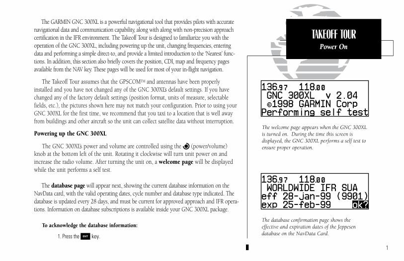
The GARMIN GNC 300XL is a powerful navigational tool that provides pilots with accuratenavigational data and communication capability, along with along with non-precision approachcertification in the IFR environment. The Takeoff Tour is designed to familiarize you with theoperation of the GNC 300XL, including powering up the unit, changing frequencies, enteringdata and performing a simple direct-to, and provide a limited introduction to the ‘Nearest’ func-tions. In addition, this section also briefly covers the position, CDI, map and frequency pagesavailable from the NAV key. These pages will be used for most of your in-flight navigation.
The Takeoff Tour assumes that the GPSCOMTM and antennas have been properlyinstalled and you have not changed any of the GNC 300XL’s default settings. If you havechanged any of the factory default settings (position format, units of measure, selectablefields, etc.), the pictures shown here may not match your configuration. Prior to using yourGNC 300XL for the first time, we recommend that you taxi to a location that is well awayfrom buildings and other aircraft so the unit can collect satellite data without interruption.
Powering up the GNC 300XL
The GNC 300XL’s power and volume are controlled using the B (power/volume)knob at the bottom left of the unit. Rotating it clockwise will turn unit power on andincrease the radio volume. After turning the unit on, a welcome page will be displayedwhile the unit performs a self test.
The database page will appear next, showing the current database information on theNavData card, with the valid operating dates, cycle number and database type indicated. Thedatabase is updated every 28 days, and must be current for approved approach and IFR opera-tions. Information on database subscriptions is available inside your GNC 300XL package.
To acknowledge the database information:
1. Press the E key.
1
The database confirmation page shows the effective and expiration dates of the Jeppesendatabase on the NavData Card.
The welcome page appears when the GNC 300XLis turned on. During the time this screen is displayed, the GNC 300XL performs a self test toensure proper operation.
TAKEOFF TOURPower On
300xl manual 1/25/99 2:35 PM Page 1
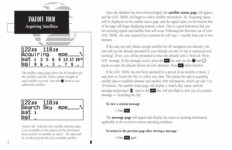
The satellite status page shows the ID numbers forthe satellites and the relative signal strength ofeach satellite received. Turn the K knob to viewadditional satellites.
TAKEOFF TOURAcquiring Satellites
‘Search Sky’ indicates that satellite almanac datais not available or has expired (if the unit hasn’tbeen used for six months or more). The data willbe recollected from the first available satellite.
Once the database has been acknowledged, the satellite status page will appear,and the GNC 300XL will begin to collect satellite information. An ‘Acquiring’ statuswill be displayed on the satellite status page, and the signal values on the bottom lineof the page will begin displaying numeric values. This is a good indication that youare receiving signals and satellite lock will occur. Following the first-time use of yourGNC 300XL, the time required for a position fix will vary — usually from one to twominutes.
If the unit can only obtain enough satellites for 2D navigation (no altitude), theunit will use the altitude provided by your altitude encoder (if one is connected andworking). If not, you will be prompted to enter the altitude with a ‘Need alt- PressNAV’ message. If this message occurs, press the N key and use the K and Oknobs to enter the altitude shown on your altimeter. Press E when finished.
If the GNC 300XL has not been operated for a period of six months or more, itmay have to ‘Search the Sky’ to collect new data. This means the unit is acquiringsatellite data to establish almanac and satellite orbit information, which can take 5 to10 minutes. The satellite status page will display a ‘Search Sky’ status, and themessage annunciator (U), next to the M key, will also flash to alert you of a systemmessage — ‘Searching the Sky’.
To view a system message:
1. Press M.
The message page will appear and display the status or warning informationapplicable to the receiver’s current operating condition.
To return to the previous page after viewing a message:
1. Press M again.2
300xl manual 1/25/99 2:35 PM Page 2
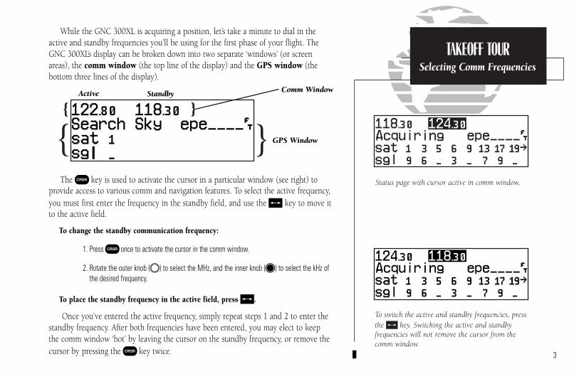
While the GNC 300XL is acquiring a position, let’s take a minute to dial in theactive and standby frequencies you’ll be using for the first phase of your flight. TheGNC 300XL’s display can be broken down into two separate ‘windows’ (or screenareas), the comm window (the top line of the display) and the GPS window (thebottom three lines of the display).
The C key is used to activate the cursor in a particular window (see right) toprovide access to various comm and navigation features. To select the active frequency,you must first enter the frequency in the standby field, and use the @ key to move itto the active field.
To change the standby communication frequency:
1. Press C once to activate the cursor in the comm window.
2. Rotate the outer knob (O) to select the MHz, and the inner knob (K) to select the kHz ofthe desired frequency.
To place the standby frequency in the active field, press @.
Once you’ve entered the active frequency, simply repeat steps 1 and 2 to enter thestandby frequency. After both frequencies have been entered, you may elect to keepthe comm window ‘hot’ by leaving the cursor on the standby frequency, or remove thecursor by pressing the C key twice. 3
Status page with cursor active in comm window.
TAKEOFF TOURSelecting Comm Frequencies
Comm Window
GPS Window
StandbyActive
}{
{ }
To switch the active and standby frequencies, pressthe @ key. Switching the active and standby frequencies will not remove the cursor from thecomm window.
300xl manual 1/25/99 2:35 PM Page 3

The map page combines a moving map displayand navigation data for complete situationalawareness.
TAKEOFF TOURPosition Page
The navigation communications (NAVCOM) pageprovides a complete list of airport frequencies atyour departure and arrival airports.
After the GNC 300XL acquires satellites and computes a position, the position page willappear automatically, and you’ll be informed with ‘Ready for navigation’ on the message page.
The position page displays your present latitude and longitude, altitude and a reference way-point field. The altitude and reference waypoint fields are also selectable (see Section 1 for moreinformation) to allow you to configure the unit to your own preferences. The default settings are:
• Altitude— Your present GPS altitude• Present Position— Latitude and longitude displayed in degrees/minutes• Reference Waypoint— The bearing and distance to the nearest airport
The position page is one of seven pages available under the GNC 300XL’s N key:
• CDI page • Map page• NAVCOM page • Position page• Satellite status page • NAV menu 1• NAV menu 2
During most flights, the position, CDI (course deviation indicator), map and NAVCOM pageswill be the primary pages used for navigation. These pages are accessible by pressing the Nkey and rotating the outer knob, or by pressing the N key repeatedly.
4
Altitude, MSA or ESA
Position (lat/lon)
Reference Waypoint Field
{
300xl manual 1/25/99 2:35 PM Page 4

The GNC 300XL uses direct point-to-point navigation to guide you from takeoffto touchdown in the IFR environment. Once a destination is selected, the unit willprovide speed, course and distance data based upon a direct course from your presentposition to your destination. A destination can be selected from any page with theD (direct-to) key.
To select a direct-to destination:
1. Press the D key. The CDI page will appear with the destination field highlighted.
2. Rotate the K knob to enter the first letter of the destination waypoint identifier. The des-tination waypoint may be an airport, VOR, NDB, intersection or user waypoint, as long asit is in the database or stored in memory as a user waypoint.
3. Rotate the O knob to the right to move the cursor to the next character position.
4. Repeat steps 2 and 3 to spell out the rest of the waypoint identifier.
5. Press E to confirm the identifier. The direct-to confirmation page will appear.
6. Press E to confirm the destination.
Once the direct-to destination is confirmed, the CDI page will appear with thedestination indicated in the lower left hand corner of the screen. Your present speedand track over the ground, and the distance and estimated time en route to your des-tination are also displayed. The graphical CDI (course deviation indicator), located atthe top left of the screen, displays your position relative to the desired course andprovides turn anticipation and waypoint messages during route navigation. 5
When a destination is selected the direct-to confirmation page appears to verify the destina-tion you selected. The lat/long, facility name orcity may be displayed by highlighting the positionfield (third display line) and rotating the K knob.
The CDI page without a direct-to destination oractive route appears blank, except for groundspeed (GS) and track (TRK) figures, if displayed.
TAKEOFF TOURDirect-To
Navigation
300xl manual 1/25/99 2:35 PM Page 5
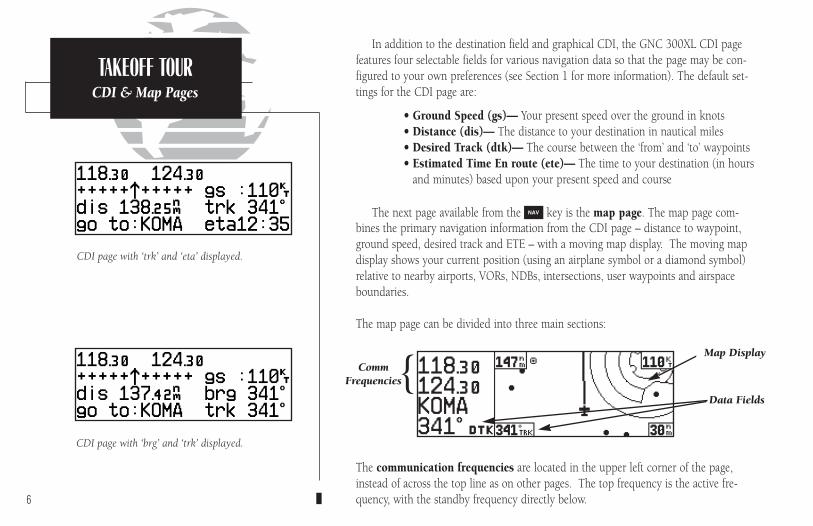
CDI page with ‘trk’ and ‘eta’ displayed.
TAKEOFF TOURCDI & Map Pages
CDI page with ‘brg’ and ‘trk’ displayed.
In addition to the destination field and graphical CDI, the GNC 300XL CDI pagefeatures four selectable fields for various navigation data so that the page may be con-figured to your own preferences (see Section 1 for more information). The default set-tings for the CDI page are:
• Ground Speed (gs)— Your present speed over the ground in knots• Distance (dis)— The distance to your destination in nautical miles• Desired Track (dtk)— The course between the ‘from’ and ‘to’ waypoints• Estimated Time En route (ete)— The time to your destination (in hours
and minutes) based upon your present speed and course
The next page available from the N key is the map page. The map page com-bines the primary navigation information from the CDI page – distance to waypoint,ground speed, desired track and ETE – with a moving map display. The moving mapdisplay shows your current position (using an airplane symbol or a diamond symbol)relative to nearby airports, VORs, NDBs, intersections, user waypoints and airspaceboundaries.
The map page can be divided into three main sections:
The communication frequencies are located in the upper left corner of the page,instead of across the top line as on other pages. The top frequency is the active fre-quency, with the standby frequency directly below.6
CommFrequencies
Data Fields{
Map Display
300xl manual 1/25/99 2:35 PM Page 6
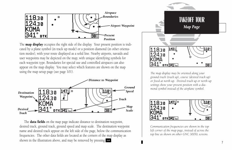
The map display occupies the right side of the display. Your present position is indi-cated by a plane symbol (in track up mode) or a position diamond (in other orienta-tion modes), with your route displayed as a solid line. Nearby airports, navaids anduser waypoints may be depicted on the map; with unique identifying symbols foreach waypoint type. Boundaries for special use and controlled airspaces can alsoappear on the map display. You may select which features are shown on the mapusing the map setup page (see page 101).
The data fields on the map page indicate distance to destination waypoint,desired track, ground track, ground speed and map scale. The destination waypointname and desired track appear on the left side of the page, below the communicationfrequencies. The other data fields are located at the corners of the map display asshown in the illustration above, and may be removed by pressing \.
7
Communication frequencies are shown in the topleft corner of the map page, instead of across thetop line as shown on other GNC 300XL screens.
The map display may be oriented along yourground track (track up), course (desired track up)or fixed at north up. Desired track up or north upsettings show your present position with a dia-mond symbol instead of the airplane symbol.
TAKEOFF TOURMap Page
PresentPosition
AirspaceBoundaries
Airport Waypoint
DestinationWaypoint
MapScale
GroundSpeed
Track
DesiredTrack
Distance to Waypoint
300xl manual 1/25/99 2:35 PM Page 7
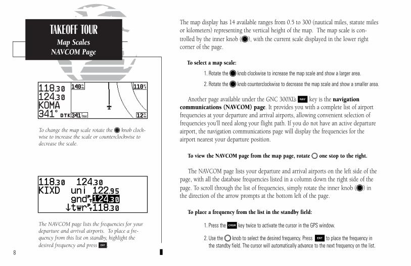
The map display has 14 available ranges from 0.5 to 300 (nautical miles, statute milesor kilometers) representing the vertical height of the map. The map scale is con-trolled by the inner knob (K), with the current scale displayed in the lower rightcorner of the page.
To select a map scale:
1. Rotate the K knob clockwise to increase the map scale and show a larger area.
2. Rotate the K knob counterclockwise to decrease the map scale and show a smaller area.
Another page available under the GNC 300XL’s N key is the navigation communications (NAVCOM) page. It provides you with a complete list of airportfrequencies at your departure and arrival airports, allowing convenient selection offrequencies you’ll need along your flight path. If you do not have an active departureairport, the navigation communications page will display the frequencies for the airport nearest your departure position.
To view the NAVCOM page from the map page, rotate O one stop to the right.
The NAVCOM page lists your departure and arrival airports on the left side of thepage, with all the database frequencies listed in a column down the right side of thepage. To scroll through the list of frequencies, simply rotate the inner knob (K) inthe direction of the arrow prompts at the bottom left of the page.
To place a frequency from the list in the standby field:
1. Press the C key twice to activate the cursor in the GPS window.
2. Use the O knob to select the desired frequency. Press E to place the frequency inthe standby field. The cursor will automatically advance to the next frequency on the list.
8
The NAVCOM page lists the frequencies for yourdeparture and arrival airports. To place a fre-quency from this list on standby, highlight thedesired frequency and press E.
To change the map scale rotate the K knob clock-wise to increase the scale or counterclockwise todecrease the scale.
TAKEOFF TOURMap Scales
NAVCOM Page
300xl manual 1/25/99 2:35 PM Page 8

Once a direct-to is activated, the CDI page will provide navigation to the destina-tion until the direct-to is cancelled or another direct-to destination is activated.
To cancel a direct-to from the CDI page:
1. Press the C key twice to activate the cursor in the destination field.
2. Press \.
3. Press E.
The GNC 300XL’s T key provides the nine nearest airports, VORs, NDBs, inter-sections, user waypoints and any SUA (special use airspace) alerts, as well as the twoclosest FSS (Flight Service Station) and center (ARTCC) frequencies for your presentposition. The nearest waypoint feature is a handy safety feature that may be used toexecute a quick direct-to in case of an in-flight emergency or to review the closest facil-ities to your present position. The nearest feature can also be used to quickly find thecontact frequency of the nearest airport and enter it in the standby field.
To view the nine nearest airports:
1. Press the T key. The nearest airport will be displayed, with the range and bearing fromyour present position, along with elevation, frequency and runway data.
2. To review the rest of the nearest airport list, rotate the K knob to the right.
To place a nearest airport frequency in the standby field:
1. Press E. Press the @ key to place the frequency in the active field.
To view the nearest list for other waypoint categories (VOR, NDB, etc.):
1. Rotate the O knob to the right, or press the T key repeatedly.
2. Rotate K to scroll through the list. 9
Additional frequencies may be displayed by press-ing C twice and rotating the K knob (or press\ repeatedly with the cursor inactive). To placea nearest airport frequency in the standby field,press E.
The nearest airport page shows up to nine nearest airports from your present position. Toview additional nearest airports, rotate the Kknob.
TAKEOFF TOURCancelling a Direct-To
Nearest Waypoints
300xl manual 1/25/99 2:35 PM Page 9

To review a nearest waypoint, highlight the identi-fier and press E.
To select a nearest waypoint as a direct to destina-tion, press D and E.
Once the nearest airport (or any other nearest waypoint) page is displayed, theselected waypoint can be quickly reviewed or selected as a direct-to destination.
To review the selected waypoint from the nearest waypoint list:
1. Press C twice to activate the waypoint field.
2. Press E to display the waypoint identification page.
3. Rotate O to view any additional waypoint information available.
4. Press T to return to the nearest waypoint page.
To select a nearest waypoint as a direct-to destination:
1. Press the D key. The direct-to confirmation page for the selected waypoint will appear.
2. Press E to confirm.
Congratulations! You’ve covered the basic operation of the GNC 300XL. Weencourage you to experiment with your new GPSCOM to get to know all theadvanced navigation features it has to offer. If you’d like a little more practice, tryusing the built-in simulator described in Appendix C. An optional AC adapter willeven let you plan and simulate flights in the comfort of your home or office.
To turn the GNC 300XL off:
1. Turn the B knob to the left until the unit shuts off.
NOTE: The GNC 300XL is normally connected to power through the avionics masterswitch. With the optional remote battery installed, the unit will display a power downwarning when the master switch is turned off. This warning page features a timer whichwill count down from 30 seconds when the unit senses that power is off. After 30 sec-onds, the GNC 300XL will shut off. If you wish to continue operating the unit, pressany key during the countdown period, and the unit will operate from the battery.10
TAKEOFF TOURNearest AirportsShutting Down
300xl manual 1/25/99 2:35 PM Page 10

Section 1 Navigation Key
The GNC 300XL features seven navigation pages to provide various position,course, speed, status and planning information. The pages may be viewed by pressingthe N key and rotating the outer knob, or by pressing the N key repeatedly.
The CDI, map, NAVCOM and position pages are the primary pages used duringin-flight navigation, while the nav menu and status pages offer access to planning, calculation and status functions. Note that rotating the outer knob clockwise will continuously cycle through all the navigation pages, whereas turning the knob coun-terclockwise will stop the page selection sequence at the CDI page.
Whenever the N key pages are in use, the indicator light (U) next to the Nkey will illuminate. If the GNC 300XL requires you to enter data on a navigationpage, a message prompt with specific instructions will appear and the indicator willflash. If you leave the NAV page sequence for another set of pages, the last NAV pagedisplayed will reappear when you return to the nav sequence. 11
SECTION
1NAV KEYOverview
Remember! The NAV pages will only displayinformation AFTER the position and navigationalinformation has been calculated from the satel-lites. If you are on the position page before the unithas calculated a position, you will be able to enteran approximate position and altitude. This is help-ful in speeding satellite acquisition if the unit hasmoved a great distance with the power off.
If you are not sure the GPS is actively calculatingposition, check the receiver status field for ‘2DNAV’ or ‘3D NAV’ by pressing the N key androtating the outer knob until the satellite statuspage appears. The current receiver status is dis-played at the top left of the page.
CDI page
NAV Menu 2 Position page
NAV Menu 1
Map page
Satellite status page
NAVCOM page
300xl manual 1/25/99 2:35 PM Page 11
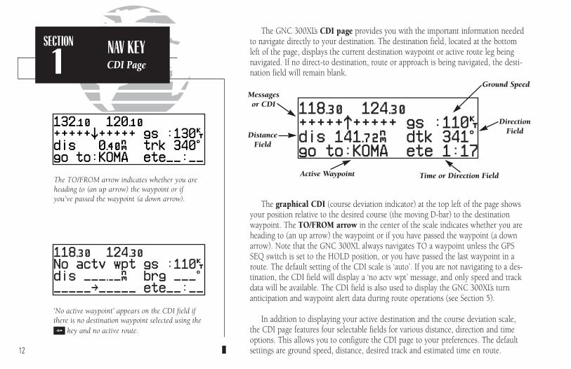
The TO/FROM arrow indicates whether you areheading to (an up arrow) the waypoint or ifyou’ve passed the waypoint (a down arrow).
‘No active waypoint’ appears on the CDI field ifthere is no destination waypoint selected using theD key and no active route.
The GNC 300XL’s CDI page provides you with the important information neededto navigate directly to your destination. The destination field, located at the bottomleft of the page, displays the current destination waypoint or active route leg beingnavigated. If no direct-to destination, route or approach is being navigated, the desti-nation field will remain blank.
The graphical CDI (course deviation indicator) at the top left of the page showsyour position relative to the desired course (the moving D-bar) to the destinationwaypoint. The TO/FROM arrow in the center of the scale indicates whether you areheading to (an up arrow) the waypoint or if you have passed the waypoint (a downarrow). Note that the GNC 300XL always navigates TO a waypoint unless the GPSSEQ switch is set to the HOLD position, or you have passed the last waypoint in aroute. The default setting of the CDI scale is ‘auto’. If you are not navigating to a des-tination, the CDI field will display a ‘no actv wpt’ message, and only speed and trackdata will be available. The CDI field is also used to display the GNC 300XL’s turnanticipation and waypoint alert data during route operations (see Section 5).
In addition to displaying your active destination and the course deviation scale,the CDI page features four selectable fields for various distance, direction and timeoptions. This allows you to configure the CDI page to your preferences. The defaultsettings are ground speed, distance, desired track and estimated time en route.12
Active Waypoint
Ground Speed
DirectionFieldDistance
Field
Messages or CDI
Time or Direction Field
SECTION
1NAV KEYCDI Page
300xl manual 1/25/99 2:35 PM Page 12

The following functions may be displayed in the ground speed field:
• gs— Your present speed over the ground.• str— Steer direction and distance, or digital crosstrack error. An ‘L’ or ‘R’
indicates which direction to steer, while the distance value indi-cates how far you are off course.
The following functions may be displayed in the distance field:
• dis— Distance from present position to the ‘active to’ waypoint.• str— Steer direction and distance, or digital crosstrack error. An ‘L’ or ‘R’
indicates which direction to steer, while the distance value indi-cates how far you are off course.
The following steering functions may be displayed in the direction field:
• brg— Bearing, the direction from your present position to the waypoint.• cts— Course to steer to reduce cross track error and re-intercept course.• dtk— Desired track, the course between the active from and to waypoints.• trk— Track, the direction of movement relative to the ground.• trn— Turn, the direction and degrees to turn to get back on course.
The following information can be displayed in the time field:
• eta— Estimated Time of Arrival (at the active to waypoint).• ete— Estimated Time En route (to the active to waypoint).• trk— Track, or the direction of movement relative to the ground.• vn— Vertical Navigation, or VNAV. If VNAV has been activated, this field
indicates either the elapsed time before the VNAV maneuver is tobegin or the VNAV altitude (the suggested altitude you should be fly-ing in order to complete the maneuver).
13
SECTION
1NAV KEY
Configuring the CDI Page
WPT 1
STR L
NORTH
NORTH
WPT 2
BRG
TRKGS
DIS
AIRPLA
NE
DTK
300xl manual 1/25/99 2:35 PM Page 13
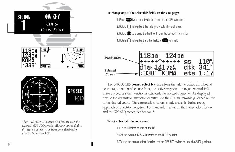
To change any of the selectable fields on the CDI page:
1. Press C twice to activate the cursor in the GPS window.
2. Rotate O to highlight the field you would like to change.
3. Rotate K to change the field to display the desired information.
4. Rotate O to highlight another field, or C to finish.
The GNC 300XL’s course select feature allows the pilot to define the inboundcourse to, or outbound course from, the ‘active’ waypoint, using an external HSI.Once the course select function is activated, the selected course will be displayednext to the destination waypoint identifier and the CDI will provide guidance relativeto the desired course. The course select feature is only available during route,approach or direct-to navigation. For more information on the course select featureand the GPS SEQ switch, see Section 6.
To set a desired inbound course:
1. Dial the desired course on the HSI.
2. Set the external GPS SEQ switch to the HOLD position.
3. To stop the course select function, set the GPS SEQ switch back to the AUTO position.14
SECTION
1NAV KEYCDI &
Course Select
The GNC 300XL’s course select feature uses theexternal GPS SEQ switch, allowing you to dial inthe desired course to or from your destinationdirectly from your HSI.
GPS SEQAUTO HOLD
OBS
TO
FR
N33
30W
24
21 S15
12E
6
3
SelectedCourse
Destination
300xl manual 1/25/99 2:35 PM Page 14
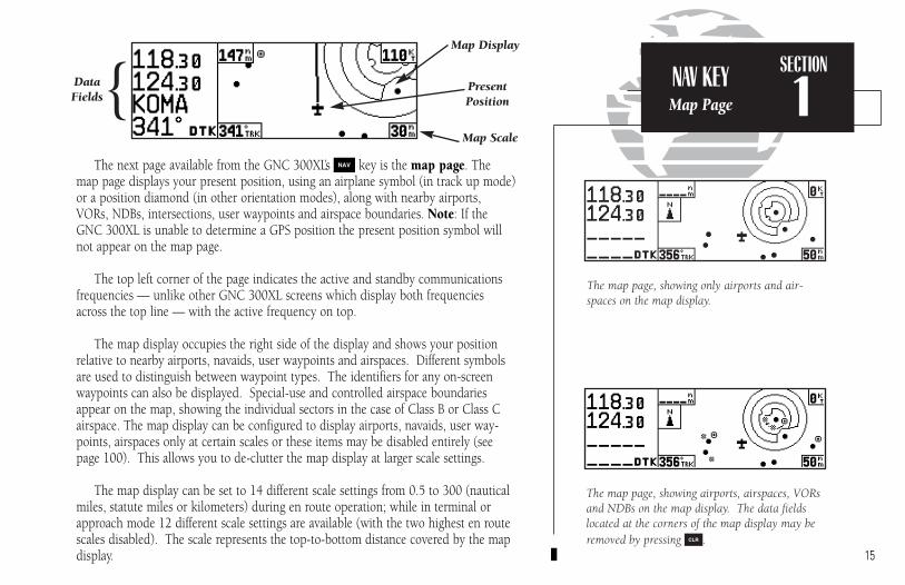
The next page available from the GNC 300XL’s N key is the map page. Themap page displays your present position, using an airplane symbol (in track up mode)or a position diamond (in other orientation modes), along with nearby airports,VORs, NDBs, intersections, user waypoints and airspace boundaries. Note: If theGNC 300XL is unable to determine a GPS position the present position symbol willnot appear on the map page.
The top left corner of the page indicates the active and standby communicationsfrequencies — unlike other GNC 300XL screens which display both frequenciesacross the top line — with the active frequency on top.
The map display occupies the right side of the display and shows your positionrelative to nearby airports, navaids, user waypoints and airspaces. Different symbolsare used to distinguish between waypoint types. The identifiers for any on-screenwaypoints can also be displayed. Special-use and controlled airspace boundariesappear on the map, showing the individual sectors in the case of Class B or Class Cairspace. The map display can be configured to display airports, navaids, user way-points, airspaces only at certain scales or these items may be disabled entirely (seepage 100). This allows you to de-clutter the map display at larger scale settings.
The map display can be set to 14 different scale settings from 0.5 to 300 (nauticalmiles, statute miles or kilometers) during en route operation; while in terminal orapproach mode 12 different scale settings are available (with the two highest en routescales disabled). The scale represents the top-to-bottom distance covered by the mapdisplay. 15
The map page, showing airports, airspaces, VORsand NDBs on the map display. The data fieldslocated at the corners of the map display may beremoved by pressing \.
The map page, showing only airports and air-spaces on the map display.
SECTION
1NAV KEYMap Page
DataFields
Present Position{
Map Display
Map Scale
300xl manual 1/25/99 2:35 PM Page 15
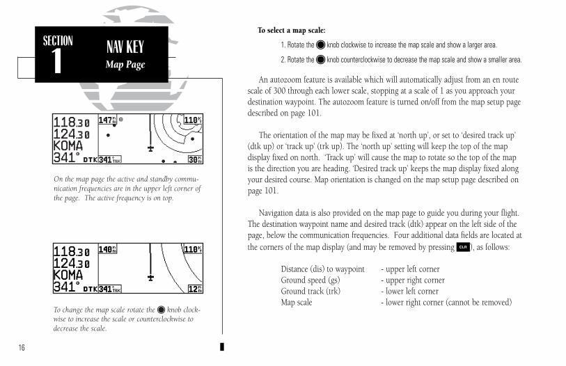
To select a map scale:
1. Rotate the K knob clockwise to increase the map scale and show a larger area.
2. Rotate the K knob counterclockwise to decrease the map scale and show a smaller area.
An autozoom feature is available which will automatically adjust from an en routescale of 300 through each lower scale, stopping at a scale of 1 as you approach yourdestination waypoint. The autozoom feature is turned on/off from the map setup pagedescribed on page 101.
The orientation of the map may be fixed at ‘north up’, or set to ‘desired track up’(dtk up) or ‘track up’ (trk up). The ‘north up’ setting will keep the top of the map display fixed on north. ‘Track up’ will cause the map to rotate so the top of the map is the direction you are heading. ‘Desired track up’ keeps the map display fixed alongyour desired course. Map orientation is changed on the map setup page described onpage 101.
Navigation data is also provided on the map page to guide you during your flight.The destination waypoint name and desired track (dtk) appear on the left side of thepage, below the communication frequencies. Four additional data fields are located atthe corners of the map display (and may be removed by pressing \), as follows:
Distance (dis) to waypoint - upper left cornerGround speed (gs) - upper right cornerGround track (trk) - lower left cornerMap scale - lower right corner (cannot be removed)
16
SECTION
1NAV KEYMap Page
To change the map scale rotate the K knob clock-wise to increase the scale or counterclockwise todecrease the scale.
On the map page the active and standby commu-nication frequencies are in the upper left corner ofthe page. The active frequency is on top.
300xl manual 1/25/99 2:35 PM Page 16
17
SECTION
1NAV KEYNAVCOM Page
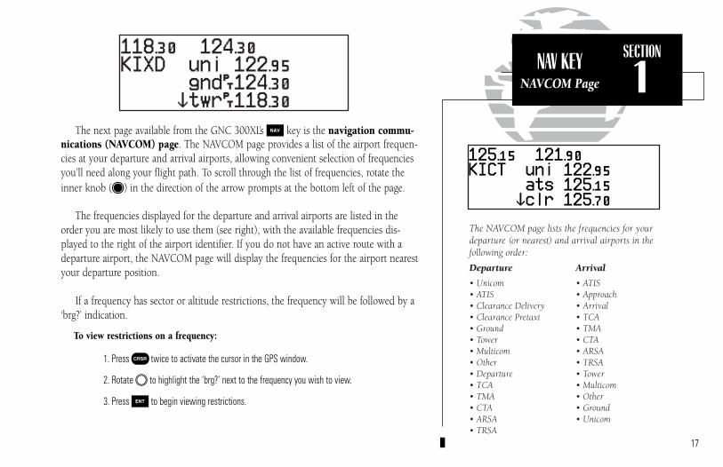
The next page available from the GNC 300XL’s N key is the navigation commu-nications (NAVCOM) page. The NAVCOM page provides a list of the airport frequen-cies at your departure and arrival airports, allowing convenient selection of frequenciesyou’ll need along your flight path. To scroll through the list of frequencies, rotate theinner knob (K) in the direction of the arrow prompts at the bottom left of the page.
The frequencies displayed for the departure and arrival airports are listed in theorder you are most likely to use them (see right), with the available frequencies dis-played to the right of the airport identifier. If you do not have an active route with adeparture airport, the NAVCOM page will display the frequencies for the airport nearestyour departure position.
If a frequency has sector or altitude restrictions, the frequency will be followed by a‘brg?’ indication.
To view restrictions on a frequency:
1. Press C twice to activate the cursor in the GPS window.
2. Rotate O to highlight the ‘brg?’ next to the frequency you wish to view.
3. Press E to begin viewing restrictions.
The NAVCOM page lists the frequencies for yourdeparture (or nearest) and arrival airports in thefollowing order:
Departure Arrival
• Unicom • ATIS• ATIS • Approach• Clearance Delivery • Arrival• Clearance Pretaxi • TCA• Ground • TMA• Tower • CTA• Multicom • ARSA• Other • TRSA• Departure • Tower• TCA • Multicom• TMA • Other• CTA • Ground• ARSA • Unicom• TRSA
300xl manual 1/25/99 2:35 PM Page 17

18
SECTION
1Once you begin viewing restrictions, you can view any additional frequencies for
the selected airport by rotating K. (Note: An arrow prompt displayed next to the air-port identifier indicates additional frequencies are available.) You can also view theother airport information pages by rotating O. Information contained on these pagesis covered in Section 3. To return to the NAVCOM page, press N.
Some frequencies in the NAVCOM page have tags which designate their usage:
‘tx’ – transmit only ‘rx’ – receive only‘pt’ – part time frequency
To make any of the frequencies on the NAVCOM page the standby frequency:
1. Press C twice to activate the cursor in the GPS window.
2. Rotate O until the desired frequency is highlighted.
3. Press E to make the highlighted frequency the standby frequency. The cursor will auto-matically advance to the next frequency on the list.
The GNC 300XL position page displays your present latitude and longitude, alti-tude and a reference waypoint field. The altitude and reference waypoint fields areselectable to configure the page to your own preferences and current navigation needs.
An altimeter setting field appears on the position page when you are within 30 nmof a destination airport. The altimeter setting field allows you to define the currentbarometric pressure, which is used by the integrity monitoring to cross check altitude.
Frequency restrictions on 124.60, showing rangeof applicable radials from 130º through 309º.
NAVCOM page with receive only (rx) frequenciesand frequencies with restrictions (brg).
NAV KEYNAVCOM &Position Pages
Altitude, MSAor ESA
Position (lat/lon)
Reference Waypoint Field
{ Altimeter SettingField
(user-selectable)
300xl manual 1/25/99 2:35 PM Page 18

19
SECTION
1
Position page displaying MSA. MSA and ESA arebased on data stored in the NavData card. Thisinformation cannot be solely relied upon as anabsolute measure of safe altitude in your area.Consult current charts and NOTAMs.
NAV KEYPosition Page &
Reference Waypoints
The same position page displaying ESA.
The altitude field can display either the present altitude, minimum safe altitude(MSA) or en route safe altitude (ESA). MSA is the recommended minimum altitudewithin a ten mile radius of your present position. ESA is the recommended minimumaltitude within a ten mile radius of your course on an active route or direct-to. MSAand ESA altitudes are calculated from information contained in the database and gen-erally include mountains, buildings and other permanent features (see right).
To change the altitude field:
1. Press C twice to obtain a cursor in the GPS window.
2. Rotate O until the ‘alt/ESA/MSA’ field is highlighted.
3. Rotate K to display the desired data. Press C to return to normal navigation.
The position page also features a reference waypoint field, located at the bottomof the page, to indicate your bearing and distance from a selected waypoint. The ref-erence waypoint field can display the following:
• Range, bearing and identifier from the nearest airport (default), VOR,NDB, intersection, or user waypoint
• Range, bearing, and identifier from a user specified waypoint
The default setting is to display the nearest airport. During DME arc approach opera-tions, the reference field will automatically display the DME reference as long as the ‘activeto’ waypoint is part of the DME arc.
To change the reference waypoint field to display the nearest airport, VOR, NDB, intersection, user waypoint or the range and bearing from a user selected waypoint:
1. Press C twice to activate the cursor in the GPS window.
2. Rotate O to highlight the category field after the fr.
300xl manual 1/25/99 2:35 PM Page 19
20
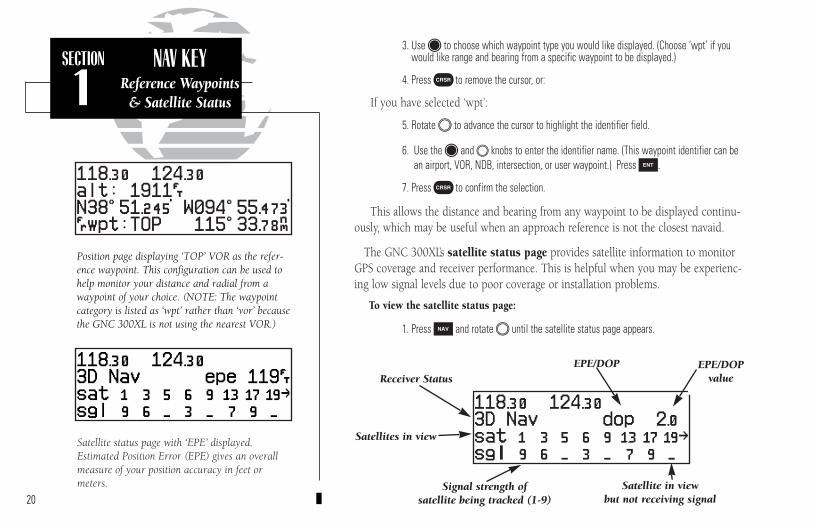
Position page displaying ‘TOP’ VOR as the refer-ence waypoint. This configuration can be used tohelp monitor your distance and radial from awaypoint of your choice. (NOTE: The waypointcategory is listed as ‘wpt’ rather than ‘vor’ becausethe GNC 300XL is not using the nearest VOR.)
SECTION
1NAV KEY
Reference Waypoints& Satellite Status
Satellite status page with ‘EPE’ displayed.Estimated Position Error (EPE) gives an overallmeasure of your position accuracy in feet ormeters.
3. Use K to choose which waypoint type you would like displayed. (Choose ‘wpt’ if youwould like range and bearing from a specific waypoint to be displayed.)
4. Press C to remove the cursor, or:
If you have selected ‘wpt’:
5. Rotate O to advance the cursor to highlight the identifier field.
6. Use the K and O knobs to enter the identifier name. (This waypoint identifier can bean airport, VOR, NDB, intersection, or user waypoint.) Press E.
7. Press C to confirm the selection.
This allows the distance and bearing from any waypoint to be displayed continu-ously, which may be useful when an approach reference is not the closest navaid.
The GNC 300XL’s satellite status page provides satellite information to monitorGPS coverage and receiver performance. This is helpful when you may be experienc-ing low signal levels due to poor coverage or installation problems.
To view the satellite status page:
1. Press N and rotate O until the satellite status page appears.
Receiver Status
Signal strength of satellite being tracked (1-9)
EPE/DOP
Satellites in view
EPE/DOPvalue
Satellite in view but not receiving signal
300xl manual 1/25/99 2:35 PM Page 20
21
SECTION
1NAV KEYSatellite
Status Page
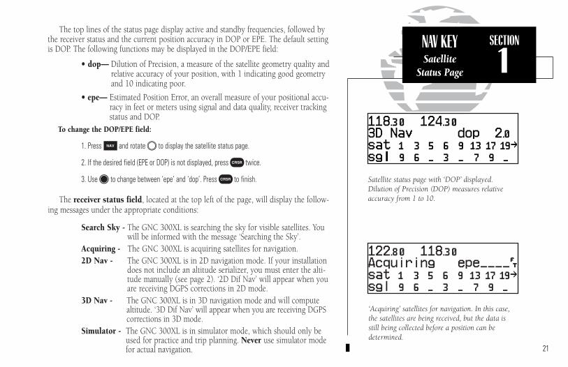
Satellite status page with ‘DOP’ displayed.Dilution of Precision (DOP) measures relativeaccuracy from 1 to 10.
The top lines of the status page display active and standby frequencies, followed bythe receiver status and the current position accuracy in DOP or EPE. The default settingis DOP. The following functions may be displayed in the DOP/EPE field:
• dop— Dilution of Precision, a measure of the satellite geometry quality andrelative accuracy of your position, with 1 indicating good geometryand 10 indicating poor.
• epe— Estimated Position Error, an overall measure of your positional accu-racy in feet or meters using signal and data quality, receiver trackingstatus and DOP.
To change the DOP/EPE field:
1. PressN and rotate O to display the satellite status page.
2. If the desired field (EPE or DOP) is not displayed, press C twice.
3. Use K to change between ‘epe’ and ‘dop’. Press C to finish.
The receiver status field, located at the top left of the page, will display the follow-ing messages under the appropriate conditions:
Search Sky - The GNC 300XL is searching the sky for visible satellites. Youwill be informed with the message ‘Searching the Sky’.
Acquiring - The GNC 300XL is acquiring satellites for navigation.2D Nav - The GNC 300XL is in 2D navigation mode. If your installation
does not include an altitude serializer, you must enter the alti-tude manually (see page 2). ‘2D Dif Nav’ will appear when youare receiving DGPS corrections in 2D mode.
3D Nav - The GNC 300XL is in 3D navigation mode and will compute altitude. ‘3D Dif Nav’ will appear when you are receiving DGPScorrections in 3D mode.
Simulator - The GNC 300XL is in simulator mode, which should only beused for practice and trip planning. Never use simulator modefor actual navigation.
‘Acquiring’ satellites for navigation. In this case,the satellites are being received, but the data isstill being collected before a position can be determined.
300xl manual 1/25/99 2:35 PM Page 21

22
SECTION
1NAV KEY
Receiver Status &Satellite Data
Viewing individual satellite information.
Poor Cvrge- The GNC 300XL cannot acquire sufficient satellites for navi-gation.
Need Alt - The GNC 300XL needs altitude in order to start/continuenavigation. Press N to display the position page and enterthe altitude.
Not Usable - The GNC 300XL is unusable due to incorrect initialization orabnormal satellite conditions. Turn the unit off and on again.
Autolocate - The GNC 300XL is looking for any satellite whose almanachas been collected. This process can take up to five minutes.
The third and fourth lines of the satellite status page provide the satellite numberand signal strength of each satellite in view. The satellite status page shows signalstrength for up to eight satellites at a time. If additional satellites are being receivedan arrow on the ‘sat’ line will indicate additional data is available.
To view additional satellites:
1. RotateK to view more satellites.
Additional information regarding each satellite’s azimuth, elevation and other datais also available.
To view individual satellite information:
1. Press N and use O to display the satellite status page.
2. Press C twice to activate the cursor in the GPS window.
3. Use O to highlight the satellite number you wish to view and press E. This will dis-play the satellite data page, showing the selected satellite’s number, elevation angle, riseor fall indication, User Range Accuracy (URA, or the range measurement accuracy asdetermined by the satellite), azimuth and signal strength.
4. Rotate K to view information for the next satellite.
5. Rotate O and press C on the satellite status page when you are finished.
‘Searching the Sky’ for satellites. No satellitealmanac data exists in the GNC 300XL. It mustbe recollected from the first available satellite.
300xl manual 1/25/99 2:35 PM Page 22

23
SECTION
1NAV KEY
NAV Menu 1Trip Planning
In addition to the other five pages, the GNC 300XL features two menu pages toperform a host of planning and navigation functions. NAV Menu 1 provides access tothe following functions:
• Trip Planning • Density altitude/true airspeed calc.• Fuel Planning • Winds aloft calculations• VNAV Planning • Checklists
To display NAV Menu 1:
1. Press N.
2. Rotate O until NAV Menu 1 is displayed.
Trip Plan is the first function listed on NAV Menu 1 and allows the pilot to viewdistance, ESA, bearing and estimated time en route (ETE) between any two waypoints,and for programmed route legs. The ground speed can be varied manually to calculateseveral possible ETEs.
To use the trip planning function:
1. Press N and rotate O until NAV Menu 1 is displayed.
2. Press C twice, then E to access trip planning.
3. Rotate K to select waypoint mode or desired route number and press E.
4. For direct-to navigation, use K and O to enter the ‘to’ and ‘from’ waypoints. Press Eto accept the waypoints. To use your present position as a waypoint, leave the waypointfield blank.
5. For route calculations, choose either ‘cum’ for cumulative data (from beginning to end) orthe leg desired by rotating K.
6. Use K and O to enter the ground speed. Press E to calculate the values and C tofinish.
Trip planning with values calculated between twowaypoints.
NAV Menu 1
300xl manual 1/25/99 2:35 PM Page 23
24
SECTION
1NAV KEY
Density Altitude &True Airspeed
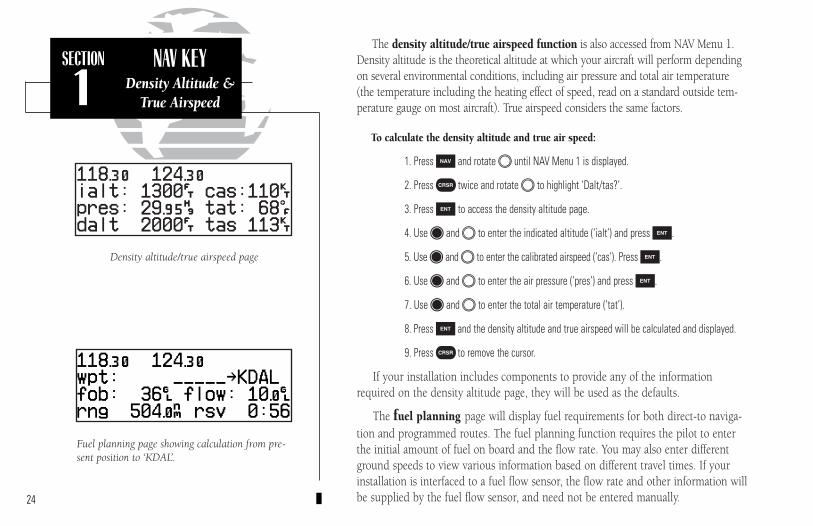
Fuel planning page showing calculation from pre-sent position to ‘KDAL’.
Density altitude/true airspeed page
The density altitude/true airspeed function is also accessed from NAV Menu 1.Density altitude is the theoretical altitude at which your aircraft will perform dependingon several environmental conditions, including air pressure and total air temperature(the temperature including the heating effect of speed, read on a standard outside tem-perature gauge on most aircraft). True airspeed considers the same factors.
To calculate the density altitude and true air speed:
1. Press N and rotate O until NAV Menu 1 is displayed.
2. Press C twice and rotate O to highlight ‘Dalt/tas?’.
3. Press E to access the density altitude page.
4. Use K and O to enter the indicated altitude (‘ialt’) and press E.
5. Use K and O to enter the calibrated airspeed (‘cas’). Press E.
6. Use K and O to enter the air pressure (‘pres’) and press E.
7. Use K and O to enter the total air temperature (‘tat’).
8. Press E and the density altitude and true airspeed will be calculated and displayed.
9. Press C to remove the cursor.
If your installation includes components to provide any of the informationrequired on the density altitude page, they will be used as the defaults.
The fuel planning page will display fuel requirements for both direct-to naviga-tion and programmed routes. The fuel planning function requires the pilot to enterthe initial amount of fuel on board and the flow rate. You may also enter differentground speeds to view various information based on different travel times. If yourinstallation is interfaced to a fuel flow sensor, the flow rate and other information willbe supplied by the fuel flow sensor, and need not be entered manually.
300xl manual 1/25/99 2:35 PM Page 24

25
SECTION
1NAV KEY
NAV Menu 1Fuel Planning
To perform fuel planning operations:
1. Press N and rotate O until NAV Menu 1 is displayed.
2. Press C twice and rotate O until ‘Fuel Plan?’ is highlighted. Press E.
3. Rotate K to select either ‘wpt’ for direct navigation or the desired route number. Press E.
4. For waypoint-waypoint navigation, use K and O to enter the ‘to’ and ‘from’ waypoints. Press E to accept the waypoints. To use the present position as a waypoint, leave thecorresponding waypoint field blank.
5. For route calculations, choose either ‘cum’ for cumulative route fuel requirements (from beginning to end) or the leg desired by rotating KK.
If leg is selected, it displays the amount of fuel required to fly until that leg is complete.
For example: The fuel required to complete leg 2 is leg 1 + leg 2. Fuel required to complete leg 4 is leg 1 + leg 2 + leg 3 + leg 4.
6. Rotate O to advance the cursor to ‘fob:’ or ‘gs:’ (depending on which is displayed).
7. Use K and O to enter the fuel on board or the ground speed. Press E.
8. Rotate O back two positions to highlight the ‘fob:’ or ‘gs:’ field again.
9. Rotate K to display the other information. Press E.
10. Use K and O to enter the remaining data. Press E.
11. Use K and O to enter the flow rate, in units per hour, if needed. Press E.
The GNC 300XL will calculate the range and endurance (i.e., how long the fuel willlast) of your aircraft. These are found in the first field on the bottom row of the page.The amount of fuel left on board (lfob) and reserve time after the selected direct-to, legor route is flown are displayed in the second field on the bottom row.
Fuel planning page with other information indicating ‘endurance’ and ‘reserve’ times.
Fuel planning page showing calculations betweentwo waypoints.
300xl manual 1/25/99 2:35 PM Page 25
26
SECTION
1NAV KEY
Winds Aloft &VNAV Functions
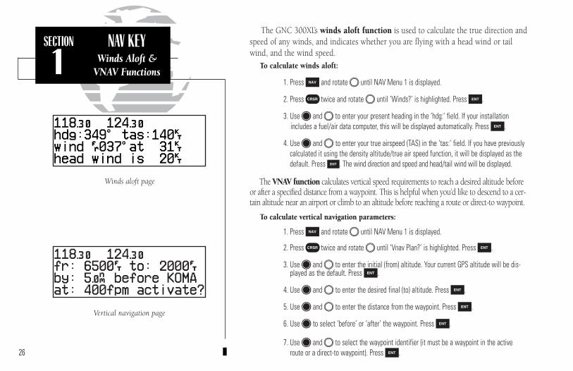
Winds aloft page
Vertical navigation page
The GNC 300XL’s winds aloft function is used to calculate the true direction andspeed of any winds, and indicates whether you are flying with a head wind or tailwind, and the wind speed.
To calculate winds aloft:
1. Press N and rotate O until NAV Menu 1 is displayed.
2. Press C twice and rotate O until ‘Winds?’ is highlighted. Press E.
3. Use K and O to enter your present heading in the ‘hdg:’ field. If your installationincludes a fuel/air data computer, this will be displayed automatically. Press E.
4. Use K and O to enter your true airspeed (TAS) in the ‘tas:’ field. If you have previouslycalculated it using the density altitude/true air speed function, it will be displayed as thedefault. Press E. The wind direction and speed and head/tail wind will be displayed.
The VNAV function calculates vertical speed requirements to reach a desired altitude beforeor after a specified distance from a waypoint. This is helpful when you’d like to descend to a cer-tain altitude near an airport or climb to an altitude before reaching a route or direct-to waypoint.
To calculate vertical navigation parameters:
1. Press N and rotate O until NAV Menu 1 is displayed.
2. Press C twice and rotate O until ‘Vnav Plan?’ is highlighted. Press E.
3. Use K and O to enter the initial (from) altitude. Your current GPS altitude will be dis-played as the default. Press E.
4. Use K and O to enter the desired final (to) altitude. Press E.
5. Use K and O to enter the distance from the waypoint. Press E.
6. Use K to select ‘before’ or ‘after’ the waypoint. Press E.
7. Use K and O to select the waypoint identifier (it must be a waypoint in the activeroute or a direct-to waypoint). Press E.
300xl manual 1/25/99 2:35 PM Page 26
27
SECTION
1NAV KEY
NAV Menu 1VNAV & Checklists
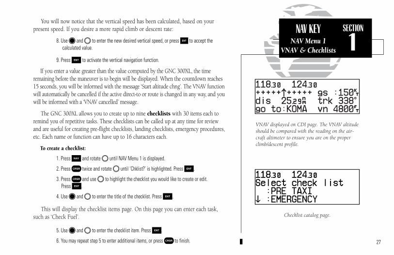
You will now notice that the vertical speed has been calculated, based on your present speed. If you desire a more rapid climb or descent rate:
8. Use K and O to enter the new desired vertical speed, or press E to accept thecalculated value.
9. Press E to activate the vertical navigation function.
If you enter a value greater than the value computed by the GNC 300XL, the timeremaining before the maneuver is to begin will be displayed. When the countdown reaches15 seconds, you will be informed with the message ‘Start altitude chng’. The VNAV functionwill automatically be cancelled if the active direct-to or route is changed in any way, and youwill be informed with a ‘VNAV cancelled’ message.
The GNC 300XL allows you to create up to nine checklists with 30 items each toremind you of repetitive tasks. These checklists can be called up at any time for reviewand are useful for creating pre-flight checklists, landing checklists, emergency procedures,etc. Each name or function can have up to 16 characters each.
To create a checklist:
1. Press N and rotate O until NAV Menu 1 is displayed.
2. Press C twice and rotate O until ‘Chklist?’ is highlighted. Press E.
3. Press C and use O to highlight the checklist you would like to create or edit.Press E.
4. Use K and O to enter the title of the checklist. Press E.
This will display the checklist items page. On this page you can enter each task,such as ‘Check Fuel’.
5. Use K and O to enter the checklist item. Press E.
6. You may repeat step 5 to enter additional items, or press C to finish.
Checklist catalog page.
VNAV displayed on CDI page. The VNAV altitudeshould be compared with the reading on the air-craft altimeter to ensure you are on the properclimb/descent profile.
300xl manual 1/25/99 2:35 PM Page 27
28
SECTION
1NAV KEYChecklists
Approach Timer
NAV Menu 2
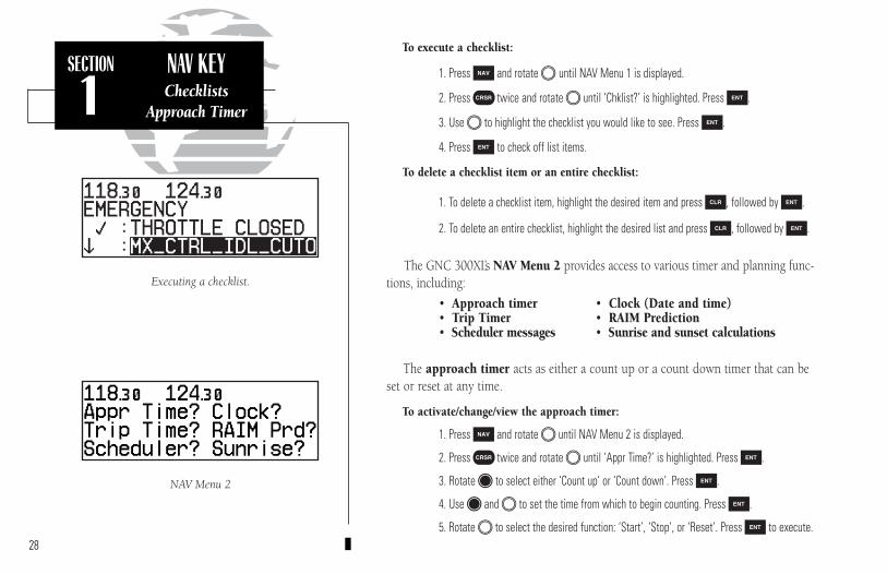
Executing a checklist.
To execute a checklist:
1. Press N and rotate O until NAV Menu 1 is displayed.
2. Press C twice and rotate O until ‘Chklist?’ is highlighted. Press E.
3. Use O to highlight the checklist you would like to see. Press E.
4. Press E to check off list items.
To delete a checklist item or an entire checklist:
1. To delete a checklist item, highlight the desired item and press \, followed by E.
2. To delete an entire checklist, highlight the desired list and press \, followed by E.
The GNC 300XL’s NAV Menu 2 provides access to various timer and planning func-tions, including:
• Approach timer • Clock (Date and time)• Trip Timer • RAIM Prediction• Scheduler messages • Sunrise and sunset calculations
The approach timer acts as either a count up or a count down timer that can beset or reset at any time.
To activate/change/view the approach timer:
1. Press N and rotate O until NAV Menu 2 is displayed.
2. Press C twice and rotate O until ‘Appr Time?’ is highlighted. Press E.
3. Rotate K to select either ‘Count up’ or ‘Count down’. Press E.
4. Use K and O to set the time from which to begin counting. Press E.
5. Rotate O to select the desired function: ‘Start’, ‘Stop’, or ‘Reset’. Press E to execute.
300xl manual 1/25/99 2:35 PM Page 28

29
SECTION
1NAV KEY
Clock FunctionTrip Timer
When the count down timer reaches zero, you will be informed with a ‘Timerexpired’ message. The timer will then begin to count up, displaying the time since itexpired. The timer runs, if not altered, whenever the GNC 300XL is turned on.
The GNC 300XL clock function keeps track of both UTC time (Greenwich MeanTime or Zulu Time calculated from the satellites) and local time, allowing you to designate which format to use for all time displays. The local time and date can be setwithout displaying local time on other GNC 300XL pages.
To set the local date/time:
1. Press N and rotate O until NAV Menu 2 is displayed.
2. Press C twice and rotate O until ‘Clock?’ is highlighted. Press E.
3. Use K to select either ‘utc’ or ’local’ time to be displayed in the time fields. Press E.
4. Use K and O to set the local date. Press E.
5. Use K and O to set the local time. Press E.
6. Press C to complete.
The GNC 300XL’s trip timer will automatically keep track of the duration of yourcurrent trip and can be configured to run either when the GNC 300XL is on, or whenyour ground speed exceeds a specified value (see Section 7).
To view or reset the trip timer:
1. Press N and rotate O until NAV Menu 2 is displayed.
2. Press C twice and rotate O until ‘Trip time?’ is highlighted. Press E. The currenttime of day, departure time and time en route will be displayed.
3. To reset the timer, press E. To skip resetting the timer, press C.
To reset the trip timer, highlight ‘Reset?’ and press E.
Clock function set to display local time in the timefields of all other GNC 300XL pages.
300xl manual 1/25/99 2:35 PM Page 29
30
SECTION
1NAV KEY
RAIM Prediction
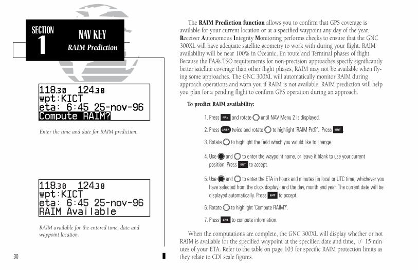
Enter the time and date for RAIM prediction.
RAIM available for the entered time, date andwaypoint location.
The RAIM Prediction function allows you to confirm that GPS coverage is available for your current location or at a specified waypoint any day of the year.Receiver Autonomous Integrity Monitoring performs checks to ensure that the GNC300XL will have adequate satellite geometry to work with during your flight. RAIMavailability will be near 100% in Oceanic, En route and Terminal phases of flight.Because the FAA’s TSO requirements for non-precision approaches specify significantlybetter satellite coverage than other flight phases, RAIM may not be available when fly-ing some approaches. The GNC 300XL will automatically monitor RAIM duringapproach operations and warn you if RAIM is not available. RAIM prediction will helpyou plan for a pending flight to confirm GPS operation during an approach.
To predict RAIM availability:
1. Press N and rotate O until NAV Menu 2 is displayed.
2. Press C twice and rotate O to highlight ‘RAIM Prd?’. Press E.
3. Rotate O to highlight the field which you would like to change.
4. Use K and O to enter the waypoint name, or leave it blank to use your current position. Press E to accept.
5. Use K and O to enter the ETA in hours and minutes (in local or UTC time, whichever youhave selected from the clock display), and the day, month and year. The current date will bedisplayed automatically. Press E to accept.
6. Rotate O to highlight ‘Compute RAIM?’.
7. Press E to compute information.
When the computations are complete, the GNC 300XL will display whether or notRAIM is available for the specified waypoint at the specified date and time, +/- 15 min-utes of your ETA. Refer to the table on page 103 for specific RAIM protection limits asthey relate to CDI scale figures.
300xl manual 1/25/99 2:35 PM Page 30

31
SECTION
1NAV KEY
NAV Menu 2Scheduler
The scheduler function will display reminder messages (such as ‘Change oil’, ‘Switchfuel tanks’, ‘Overhaul’, etc) after a specified time has elapsed. For example, if you enter‘Change oil’ to be displayed in 30 hours, the message ‘Change oil’ will be displayed after theGNC 300XL has been running in Normal mode for 30 hours. After appearing, the messagewill be displayed each time the GNC 300XL is turned on until it is changed or deleted.
To enter a scheduled message:
1. Press N and rotate O to display NAV Menu 2.
2. Press C twice and rotate O until ‘Scheduler?’ is highlighted.
3. Press E.
4. Rotate O to highlight the message you would like to edit. To delete, press \, then E.
5. Use K and O to enter the message. Press E.
6. Use K and O to set the time to elapse before the message is displayed, in hours andminutes, up to 99 hours and 59 minutes (this time is cumulative and counts wheneverthe GNC 300XL is on in normal operating mode).
7. Press E.
You may edit another scheduled message by repeating steps 4, 5, 6 and 7, or if you arefinished, press C.
The scheduled message will appear after the timerexpires and reappear every time the GNC 300XLis powered on until the message is changed.
The scrolling arrow prompt indicates which direc-tion to scroll to view additional listings.
300xl manual 1/25/99 2:35 PM Page 31
32
SECTION
1NAV KEY
Sunrise/SunsetCalculations
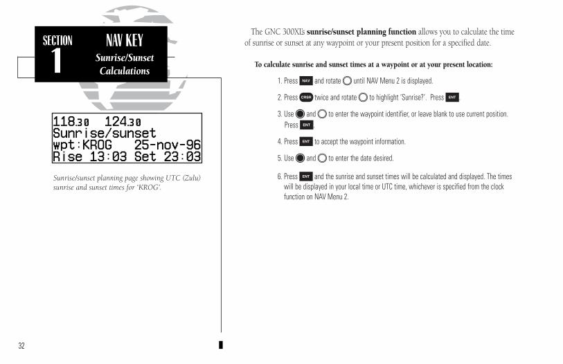
Sunrise/sunset planning page showing UTC (Zulu)sunrise and sunset times for ‘KROG’.
The GNC 300XL’s sunrise/sunset planning function allows you to calculate the timeof sunrise or sunset at any waypoint or your present position for a specified date.
To calculate sunrise and sunset times at a waypoint or at your present location:
1. Press N and rotate O until NAV Menu 2 is displayed.
2. Press C twice and rotate O to highlight ‘Sunrise?’. Press E.
3. Use K and O to enter the waypoint identifier, or leave blank to use current position. Press E.
4. Press E to accept the waypoint information.
5. Use K and O to enter the date desired.
6. Press E and the sunrise and sunset times will be calculated and displayed. The timeswill be displayed in your local time or UTC time, whichever is specified from the clockfunction on NAV Menu 2.
300xl manual 1/25/99 2:35 PM Page 32

33
SECTION
2COMM FEATURESOverview
Section 2Communicating with the GNC 300XL
The GNC 300XL features a digital VHF radio that provides a seamless transitionfrom communication to navigation, bringing the two most important functions in fly-ing together in one panel-mount unit. The GNC 300XL operates in the aviation voiceband, from 118.000 to 136.975 MHz, in 25 kHz steps.
Communication frequencies are selected by activating the cursor in the standbyfrequency field and using the inner and outer knobs to dial in the desired frequency.A frequency may also be quickly selected from the navigation database by simplyhighlighting the frequency and pressing the E key. Once a desired frequency is dis-played in the standby field, it may be made the active frequency by pressing the @key. Note that the active frequency may not by accessed directly. Whenever the cursor isactive in the comm window, the standby frequency will be highlighted.
To access the standby frequency, press C.
This allows you to change the megahertz (number to the left of the decimal) byrotating O and the kilohertz (number to the right of the decimal) by rotating K. Ifyou would like to keep the standby field ‘hot’ (ready for an immediate frequencychange), leave the cursor active in the comm window. To remove the cursor, pressC twice after you have selected the desired frequency.
To make the standby frequency the active frequency, press @.
The frequencies will be flip-flopped and you’ll be able to transmit and receive onthe frequency previously entered as standby. This can be done at any time, regardlessof cursor or GPS status.
CDI page with standby field active. To flip-flop thefrequencies, press @.
CDI page with cursor inactive.
300xl manual 1/25/99 2:35 PM Page 33

34
SECTION
2COMM FEATURES
OverviewAuto-Tuning
To auto-tune from the nearest airport page, press E.
To select a frequency from a list, highlight thedesired frequency and press E.
During the course of navigating with the GNC 300XL, there may be times whenyou need to quickly select a comm frequency while you are entering data in the GPSwindow. Whenever data entry in the GPS window is interrupted by activating thestandby frequency field, the GPS field in use will become ‘splatted’, or blocked out.
Once the standby frequency has been entered, you may return to data entry bypressing the C key. The cursor will return to the active GPS field at the point wheredata entry was interrupted.
The GNC 300XL’s auto-tune feature allows you to quickly select any databasefrequency in the GPS window as your standby frequency.
To auto-tune a single frequency displayed in the GPS window:
1. Press E with the cursor inactive.
2. To make the standby frequency the active frequency, press @.
To auto-tune a frequency from a list displayed in the GPS window:
1. Press C twice to activate the cursor in the GPS window.
2. Rotate O to highlight the desired frequency.
3. Press E to make the selected frequency the standby frequency.
Another useful feature integrating the GNC 300XL’s navigation and communica-tion capabilities is the Navigation Communications (NAVCOM) page, which isaccessed using the N key. See pages 17-18 for more on the NAVCOM page.
300xl manual 1/25/99 2:35 PM Page 34
35
SECTION
2COMM FEATURESSquelch & VolumeEmergency Channel
The GNC 300XL’s automatic squelch and volume controls are located at thebottom left of the unit, near the NavData card slot.
To adjust the radio volume:
1. Rotate the B knob.
Whenever the GNC 300XL is powered up, the automatic squelch will be in the‘on’ position, allowing only transmissions which are powerful enough for clear broad-cast to be received. Manual squelch control is not available.
To override the automatic squelch control:
1. Press the Q key. Press Q again to return to automatic squelch.
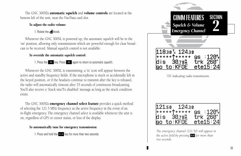
Whenever the GNC 300XL is transmitting, a ‘tx’ icon will appear between theactive and standby frequency fields. If the microphone is stuck or accidentally left inthe keyed position, or if the headsets continue to transmit after the key is released,the radio will automatically timeout after 35 seconds of continuous broadcasting.You’ll also receive a ‘Stuck mic/Tx disabled’ message as long as the stuck conditionexists.
The GNC 300XL’s emergency channel select feature provides a quick methodof selecting the 121.5 MHz frequency as the active frequency in the event of an in-flight emergency. The emergency channel select is available whenever the unit ison, regardless of GPS or cursor status, or loss of the display.
To automatically tune for emergency transmission:
1. Press and hold the @ key for more than two seconds.
‘TX’ indicating radio transmission.
The emergency channel (121.50) will appear inthe active field by pressing @ for more than two seconds.
300xl manual 1/25/99 2:35 PM Page 35
36
SECTION
3WPT KEYOverview
Section 3 Waypoint and Database Information
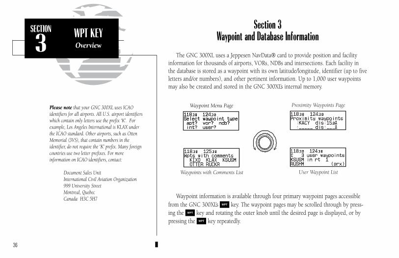
The GNC 300XL uses a Jeppesen NavData® card to provide position and facilityinformation for thousands of airports, VORs, NDBs and intersections. Each facility inthe database is stored as a waypoint with its own latitude/longitude, identifier (up to fiveletters and/or numbers), and other pertinent information. Up to 1,000 user waypointsmay also be created and stored in the GNC 300XL’s internal memory.
Waypoint information is available through four primary waypoint pages accessiblefrom the GNC 300XL’s W key. The waypoint pages may be scrolled through by press-ing the W key and rotating the outer knob until the desired page is displayed, or bypressing the W key repeatedly.
Please note that your GNC 300XL uses ICAO identifiers for all airports. All U.S. airport identifierswhich contain only letters use the prefix ‘K’. Forexample, Los Angeles International is KLAX underthe ICAO standard. Other airports, such as OttenMemorial (3VS), that contain numbers in the identifier, do not require the ‘K’ prefix. Many foreigncountries use two letter prefixes. For more information on ICAO identifiers, contact:
Document Sales UnitInternational Civil Aviation Organization999 University StreetMontreal, QuebecCanada H3C 5H7
Waypoint Menu Page Proximity Waypoints Page
Waypoints with Comments List User Waypoint List
300xl manual 1/25/99 2:35 PM Page 36
37
SECTION
3WPT KEY
Waypoint Categories& Menu Page
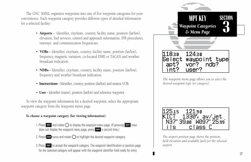
The waypoint menu page allows you to select thedesired waypoint type (or category).
The airport position page shows the position, field elevation and available fuels for the selectedairport.
The GNC 300XL organizes waypoints into one of five waypoint categories for yourconvenience. Each waypoint category provides different types of detailed informationfor a selected facility:
• Airports - Identifier, city/state, country, facility name, position (lat/lon),elevation, fuel services, control and approach information, IFR procedures,runways and communication frequencies.
• VORs - Identifier, city/state, country, facility name, position (lat/lon), frequency, magnetic variation, co-located DME or TACAN and weatherbroadcast indication.
• NDBs - Identifier, city/state, country, facility name, position (lat/lon), frequency and weather broadcast indication.
• Intersections - Identifier, country, position (lat/lon) and nearest VOR.
• User - Identifier (name), position (lat/lon) and reference waypoint.
To view the waypoint information for a desired waypoint, select the appropriatewaypoint category from the waypoint menu page.
To choose a waypoint category (for viewing information):
1. Press W and rotate O to display the waypoint menu page. (If pressing W oncedoes not display the waypoint menu page, press W a second time.)
2. Press C twice and rotate O to highlight the desired waypoint category.
3. Press E to accept the waypoint category. The waypoint identification or position pagefor the selected category will appear with the waypoint identifier field ready for entry.
300xl manual 1/25/99 2:35 PM Page 37

38
SECTION
3WPT KEY
Entering Waypoints
After a waypoint category is selected, information for a waypoint may be viewedby entering the identifier or name of the desired waypoint. Airports, VORs and NDBsmay be entered by either the identifier, name or the location (city) of the facility.Intersections and user waypoints must be entered by the identifier.
To enter a waypoint identifier:
1. With the cursor over the waypoint field, use K and O to enter the waypoint identifier.
As the identifier is entered, the GNC 300XL’s Spell’N’FindTM feature will scrollthrough the available database, displaying those waypoints matching the identifier let-ters you have entered to that point. When the desired waypoint is displayed, pressC to remove the cursor.
To obtain waypoint information by entering the facility name of the airport ornavaid, or its location:
1. Press W and rotate O to display the waypoint menu page.
2. Press C twice and rotate O to highlight the desired waypoint category.
3. Press E to accept the waypoint category.
4. Rotate O to highlight the middle field to enter location (city) OR:
Rotate O to highlight the bottom field to enter facility name or VOR/NDB name.
5. Use K and O to enter the location or the name, and press C to finish.
As the information is entered, the GNC 300XL will display any entries in its data-base that match the letters you have entered. If duplicate entries exist for the enteredidentifier, name or location, additional entries may be viewed by rotating K. Oncethe desired waypoint is displayed, press C to continue.
Entering a waypoint by city. Note that punctua-tion marks are not used when entering locationsor names. Use spaces, where appropriate, to iden-tify these marks. For example, St. Louis would beentered as “ST LOUIS” without a period.
Entering a waypoint by identifier.
300xl manual 1/25/99 2:35 PM Page 38
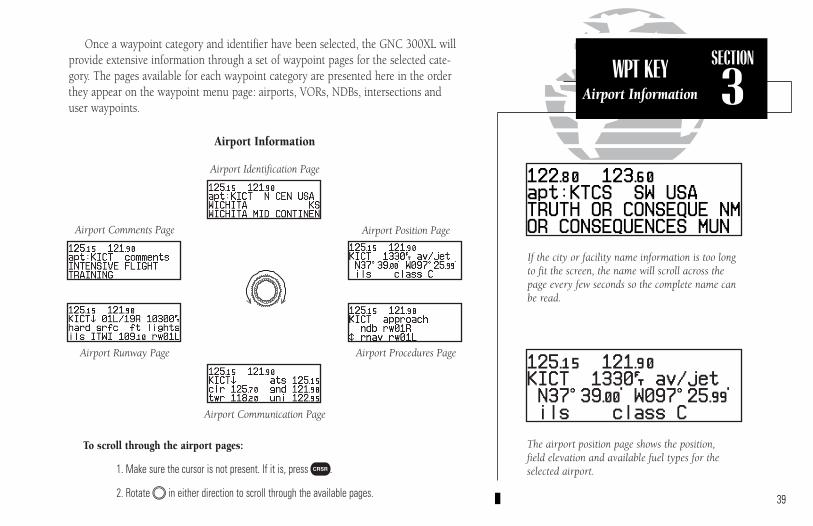
39
SECTION
3WPT KEYAirport Information
If the city or facility name information is too longto fit the screen, the name will scroll across thepage every few seconds so the complete name canbe read.
The airport position page shows the position, field elevation and available fuel types for theselected airport.
Once a waypoint category and identifier have been selected, the GNC 300XL willprovide extensive information through a set of waypoint pages for the selected cate-gory. The pages available for each waypoint category are presented here in the orderthey appear on the waypoint menu page: airports, VORs, NDBs, intersections anduser waypoints.
Airport Information
To scroll through the airport pages:
1. Make sure the cursor is not present. If it is, press C.
2. Rotate O in either direction to scroll through the available pages.
Airport Position Page
Airport Identification Page
Airport Comments Page
Airport Runway Page Airport Procedures Page
Airport Communication Page
300xl manual 1/25/99 2:35 PM Page 39
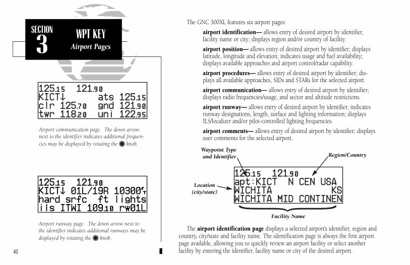
40
SECTION
3WPT KEY
Airport Pages
The GNC 300XL features six airport pages:
airport identification— allows entry of desired airport by identifier, facility name or city; displays region and/or country of facility.
airport position— allows entry of desired airport by identifier; displayslatitude, longitude and elevation; indicates usage and fuel availability; displays available approaches and airport control/radar capability.
airport procedures— allows entry of desired airport by identifier; dis-plays all available approaches, SIDs and STARs for the selected airport.
airport communication— allows entry of desired airport by identifier;displays radio frequencies/usage, and sector and altitude restrictions.
airport runway— allows entry of desired airport by identifier; indicatesrunway designations, length, surface and lighting information; displaysILS/localizer and/or pilot-controlled lighting frequencies.
airport comments— allows entry of desired airport by identifier; displaysuser comments for the selected airport.
The airport identification page displays a selected airport’s identifier, region andcountry, city/state and facility name. The identification page is always the first airportpage available, allowing you to quickly review an airport facility or select anotherfacility by entering the identifier, facility name or city of the desired airport.
Airport runway page. The down arrow next tothe identifier indicates additional runways may bedisplayed by rotating the K knob.
Airport communication page. The down arrownext to the identifier indicates additional frequen-cies may be displayed by rotating the K knob.
Waypoint Typeand Identifier Region/Country
Location(city/state)
Facility Name
{
300xl manual 1/25/99 2:35 PM Page 40

41
SECTION
3WPT KEYAirport
Position Page
1 2 3
654
The airport position page displays the latitude, longitude and elevation of theselected airport, as well as usage or fuel availability, available approaches and airportcontrol/radar capability. The following descriptions and abbreviations are used on theairport position page:
Elevation— In feet or metersUsage/Fuel— If the airport is for military use, it will display ‘military’.
If it is private, the GNC 300XL will display ‘private’. If it is apublic airport, it will display the fuel type(s) available:
• av gas— 80-87 octane, 100 LL, 100-130 octane, or mogas isavailable
• jet— Jet A, Jet A-1 or Jet A+ fuel is available• av/jet— Both av gas and jet fuel are available
Position— In degrees/minutes or degrees/minutes/seconds of latitude and longitude.
Approach Information— displays the airport approaches available• no apr— No approach is available• np-apr— Non-precision approach is available• loc— Localizer approach is available• ils— ILS approach is available
Controlled Airspace Information— displays controlled airspace type• class B • cta• class C • tma
Radar— displays approach/departure radar capability• radar— indicates radar is present
Airport Position Page
1. Identifier (selectable)2. Elevation3. Fuel Availability4. Airport Position5. Approach Information6. Controlled Airspace/Radar Capability
300xl manual 1/25/99 2:35 PM Page 41

42
SECTION
3WPT KEY
Airport ProceduresPage
The airport procedures page displays all the available approaches, SIDs andSTARs at any selected airport in the database, without placing a specific approach,SID or STAR in the active route. This allows the pilot to quickly scan the proceduresof any nearby airport in case of an emergency or help plan future flights. You mayview the available non-precision approaches, SIDs or STARs by selecting the desiredlist from the procedure type field.
To view the available procedures for a selected airport:
1. Press W and rotate O to display the airport procedures page.
2. Press C twice and rotate O to highlight the procedure field.
3. Rotate K to select the approach, SID or STAR list.
4. Press C to remove the cursor.
Whenever there are more than two available procedures for a selected category,the GNC 300XL will display a scrolling arrow prompt on the left side of the list. Toview additional procedures, simply rotate K with the cursor removed. As you scrollthrough the list, the arrow prompt will point “down” to indicate additional listingsbelow the displayed procedures, “up” to indicate additional listings above, or a “dou-ble arrow” to indicate the list may be scrolled up or down.
STAR Procedures Page
SID Procedures Page
Airport Identifier(selectable)
Procedure Type(selectable)
Scrolling ArrowPrompt Available Procedures
300xl manual 1/25/99 2:35 PM Page 42
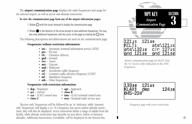
The airport communication page displays the radio frequencies and usage forthe selected airport, as well as sector and altitude restrictions.
To view the communication page from any of the airport information pages:
1. Rotate O with the cursor removed to display the communication page.
2. Rotate K in the direction of the arrow prompt to view additional frequencies. You mayalso view additional frequencies with the cursor on the page by rotating the O knob.
The following descriptions and abbreviations are used on the communication page:
Frequencies without restriction information:
• ats - Automatic terminal information service (ATIS)• ptx - Pre-taxi• clr - Clearance delivery• gnd - Ground• twr - Tower• uni - Unicom• mul - Multicom• atf - Aerodrome traffic frequency• ctf - Common traffic advisory frequency (CTAF)• mf - Mandatory frequency• oth - Other frequencies
Frequencies with restriction information:
• dep - Departure • apr - Approach• arv - Arrival • class B• cta - ICAO control area • tma - ICAO terminal control area• class C • trsa - Terminal radar service area
‘Receive only’ frequencies will be followed by an ‘rx’ indicator, while ‘transmitonly’ frequencies will display a ‘tx’. If a frequency has sector and/or altitude restric-tions, they will also be displayed. Sector restrictions define a range of radials from the facility, while altitude restrictions may describe an area above, below or between altitudes. Additional instructions, if available, will be displayed on the bottom line. 43
SECTION
3WPT KEYAirport
Communication Page
Frequency page with sector restrictions.
Airport communications page for KCLT. Note the ‘rx’ (receive only) indication on the ATIS frequencies.
300xl manual 1/25/99 2:35 PM Page 43
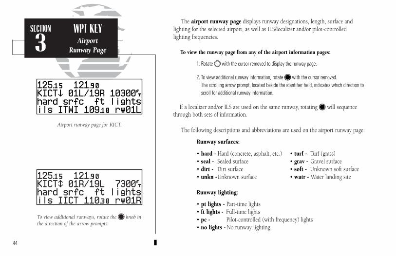
Airport runway page for KICT.
To view additional runways, rotate the K knob inthe direction of the arrow prompts.
SECTION
3WPT KEY
AirportRunway Page
44
The airport runway page displays runway designations, length, surface andlighting for the selected airport, as well as ILS/localizer and/or pilot-controlled lighting frequencies.
To view the runway page from any of the airport information pages:
1. Rotate O with the cursor removed to display the runway page.
2. To view additional runway information, rotate K with the cursor removed. The scrolling arrow prompt, located beside the identifier field, indicates which direction toscroll for additional runway information.
If a localizer and/or ILS are used on the same runway, rotating K will sequencethrough both sets of information.
The following descriptions and abbreviations are used on the airport runway page:
Runway surfaces:
• hard - Hard (concrete, asphalt, etc.) • turf - Turf (grass)• seal - Sealed surface • grav - Gravel surface• dirt - Dirt surface • soft - Unknown soft surface• unkn -Unknown surface • watr - Water landing site
Runway lighting:
• pt lights - Part-time lights• ft lights - Full-time lights• pc - Pilot-controlled (with frequency) lights• no lights - No runway lighting
300xl manual 1/25/99 2:35 PM Page 44
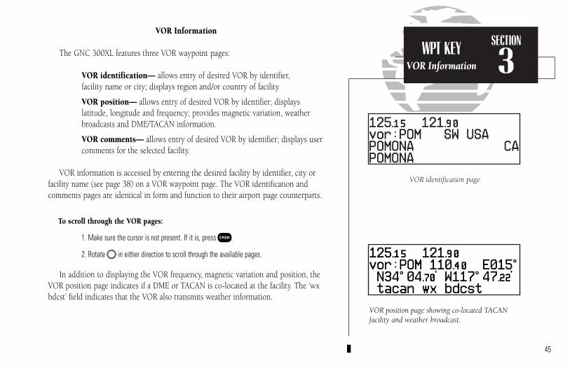
VOR position page showing co-located TACANfacility and weather broadcast.
VOR identification page
SECTION
3WPT KEYVOR Information
VOR Information
The GNC 300XL features three VOR waypoint pages:
VOR identification— allows entry of desired VOR by identifier, facility name or city; displays region and/or country of facility.
VOR position— allows entry of desired VOR by identifier; displays latitude, longitude and frequency; provides magnetic variation, weatherbroadcasts and DME/TACAN information.
VOR comments— allows entry of desired VOR by identifier; displays usercomments for the selected facility.
VOR information is accessed by entering the desired facility by identifier, city orfacility name (see page 38) on a VOR waypoint page. The VOR identification andcomments pages are identical in form and function to their airport page counterparts.
To scroll through the VOR pages:
1. Make sure the cursor is not present. If it is, press C.
2. Rotate O in either direction to scroll through the available pages.
In addition to displaying the VOR frequency, magnetic variation and position, theVOR position page indicates if a DME or TACAN is co-located at the facility. The ‘wxbdcst’ field indicates that the VOR also transmits weather information.
45
300xl manual 1/25/99 2:35 PM Page 45

NDB comments page
NDB identification page
SECTION
3WPT KEY
NDB Information
NDB Information
The GNC 300XL also uses identification, position and comments pages for NDBinformation. The NDB waypoint pages are used in the same manner as VOR pages:NDB information is accessed by entering the desired facility’s identifier, city or name(see page 38) on the NDB identification page.
To scroll through the NDB pages:
1. Make sure the cursor is not present. If it is, press C.
2. Rotate O in either direction to scroll through the available pages.
The NDB position page (see above) displays the selected facility’s identifier, fre-quency and position, as well as any weather broadcasts available. The NDB commentpage will display any user comments for the selected NDB (see page 54 for instruc-tions on entering user comments).
46
NDB Position Page
300xl manual 1/25/99 2:35 PM Page 46
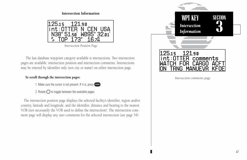
WPT KEYIntersectionInformation
SECTION
3
Intersection comments page
Intersection Information
The last database waypoint category available is intersections. Two intersectionpages are available: intersection position and intersection comments. Intersectionsmay be entered by identifier only (not city or name) on either intersection page.
To scroll through the intersection pages:
1. Make sure the cursor is not present. If it is, press C.
2. Rotate O to toggle between the available pages.
The intersection position page displays the selected facility’s identifier, region and/orcountry, latitude and longitude, and the identifier, distance and bearing to the nearestVOR (not necessarily the VOR used to define the intersection). The intersection com-ment page will display any user comments for the selected intersection (see page 54).
47
Intersection Position Page
300xl manual 1/25/99 2:35 PM Page 47
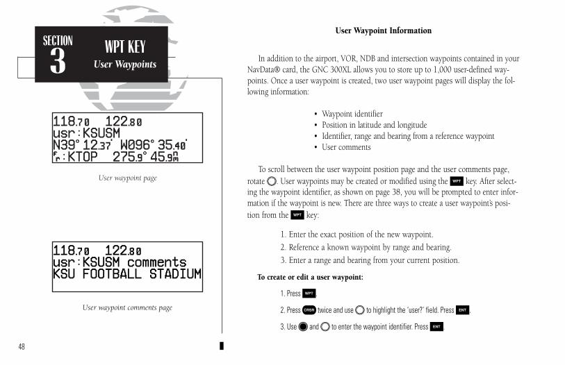
User waypoint comments page
User waypoint page
SECTION
3WPT KEY
User Waypoints
User Waypoint Information
In addition to the airport, VOR, NDB and intersection waypoints contained in yourNavData® card, the GNC 300XL allows you to store up to 1,000 user-defined way-points. Once a user waypoint is created, two user waypoint pages will display the fol-lowing information:
• Waypoint identifier• Position in latitude and longitude• Identifier, range and bearing from a reference waypoint• User comments
To scroll between the user waypoint position page and the user comments page,rotate O. User waypoints may be created or modified using the W key. After select-ing the waypoint identifier, as shown on page 38, you will be prompted to enter infor-mation if the waypoint is new. There are three ways to create a user waypoint’s posi-tion from the W key:
1. Enter the exact position of the new waypoint.
2. Reference a known waypoint by range and bearing.
3. Enter a range and bearing from your current position.
To create or edit a user waypoint:
1. Press W.
2. Press C twice and use O to highlight the ‘user?’ field. Press E.
3. Use K and O to enter the waypoint identifier. Press E.
48
300xl manual 1/25/99 2:35 PM Page 48
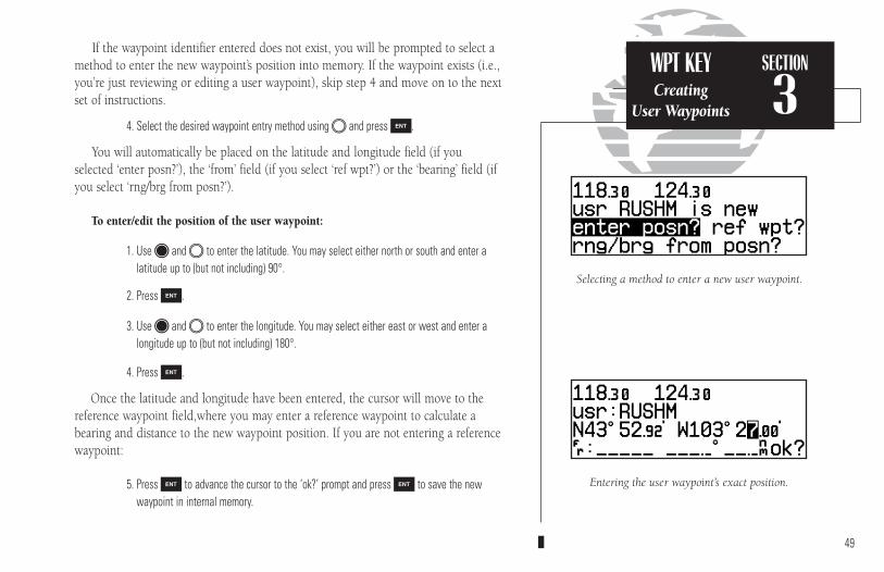
WPT KEYCreating
User Waypoints
SECTION
3
Selecting a method to enter a new user waypoint.
Entering the user waypoint’s exact position.
If the waypoint identifier entered does not exist, you will be prompted to select amethod to enter the new waypoint’s position into memory. If the waypoint exists (i.e.,you’re just reviewing or editing a user waypoint), skip step 4 and move on to the nextset of instructions.
4. Select the desired waypoint entry method using O and press E.
You will automatically be placed on the latitude and longitude field (if you selected ‘enter posn?’), the ‘from’ field (if you select ‘ref wpt?’) or the ‘bearing’ field (ifyou select ‘rng/brg from posn?’).
To enter/edit the position of the user waypoint:
1. Use K and O to enter the latitude. You may select either north or south and enter a latitude up to (but not including) 90°.
2. Press E.
3. Use K and O to enter the longitude. You may select either east or west and enter alongitude up to (but not including) 180°.
4. Press E.
Once the latitude and longitude have been entered, the cursor will move to thereference waypoint field,where you may enter a reference waypoint to calculate abearing and distance to the new waypoint position. If you are not entering a referencewaypoint:
5. Press E to advance the cursor to the ‘ok?’ prompt and press E to save the newwaypoint in internal memory.
49
300xl manual 1/25/99 2:35 PM Page 49
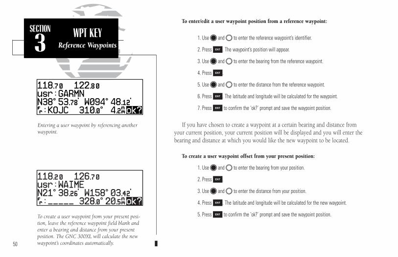
SECTION
3WPT KEY
Reference Waypoints
Entering a user waypoint by referencing anotherwaypoint.
To create a user waypoint from your present posi-tion, leave the reference waypoint field blank andenter a bearing and distance from your presentposition. The GNC 300XL will calculate the newwaypoint’s coordinates automatically.
To enter/edit a user waypoint position from a reference waypoint:
1. Use K and O to enter the reference waypoint’s identifier.
2. Press E. The waypoint’s position will appear.
3. Use K and O to enter the bearing from the reference waypoint.
4. Press E.
5. Use K and O to enter the distance from the reference waypoint.
6. Press E. The latitude and longitude will be calculated for the waypoint.
7. Press E to confirm the ‘ok?’ prompt and save the waypoint position.
If you have chosen to create a waypoint at a certain bearing and distance fromyour current position, your current position will be displayed and you will enter thebearing and distance at which you would like the new waypoint to be located.
To create a user waypoint offset from your present position:
1. Use K and O to enter the bearing from your position.
2. Press E.
3. Use K and O to enter the distance from your position.
4. Press E. The latitude and longitude will be calculated for the new waypoint.
5. Press E to confirm the ‘ok?’ prompt and save the waypoint position.
50
300xl manual 1/25/99 2:35 PM Page 50

SECTION
3WPT KEY
Creating Waypointswith AutoStore
AutoStore waypoint with default name.
The default waypoint name may be changedbefore saving the waypoint.
The GNC 300XL’s AutoStoreTM function provides another method of creatinguser waypoints. AutoStore is used to instantly capture your present position as a userwaypoint with a touch of a button and add the new waypoint to the end of a specifiedroute, if desired.
To perform an AutoStore:
1. Press N and rotate O to display the position page or map page.
2. Press E.
This will display the ‘Save waypoint’ screen, which will allow you to rename thewaypoint and choose the route to which it should be added. The GNC 300XL willassign the next available three-digit number as the default waypoint name, precededby a ‘+’ sign. This will help you differentiate AutoStore waypoints from other userwaypoints.
To change the default name or route of an AutoStore waypoint:
1. Rotate O to select the name or route number field.
2. Use K and O to enter the name or route number. If you do not want to add the way-point to a route, be sure to keep the route field blank.
3. Press E to accept.
4. Press E to confirm the ‘ok?’ prompt.
If the waypoint name you entered is already assigned to another waypoint, youwill be informed with the message ‘WPT exists ______’. The default waypoint namewill be redisplayed, and you may enter a different name. The new waypoint will onlybe added to a route if the desired route number is manually entered in the route field.
51
300xl manual 1/25/99 2:35 PM Page 51

Proximity alarm message. Pressing N will display the position page with the bearing and distance from the proximity waypoint indicated on the bottom line.
Proximity waypoints page
SECTION
3WPT KEY
Proximity Waypoints
The second page available from the GNC 300XL’s W key is the proximity waypoints page. This page allows you to define an alarm circle around a selectedwaypoint and is useful in defining alarm circles around towers or obstructions. Up tonine proximity waypoints can be entered, each with an alarm radius of up to 99.9 nm.
To create or edit a proximity waypoint:
1. Press W and use O to display the ‘Proximity waypoints’ page.
2. Press C twice and use O to highlight the first available field.
3. Use K and O to enter the identifier. It may be an airport, VOR, NDB, intersection or user waypoint. Press E.
4. Use K and O to enter the radius of the alarm circle. Press E.
If two proximity waypoints are entered and their regions overlap, you will beinformed with the message ‘Proximity overlap’. This message will be displayed eachtime you turn on the GNC 300XL for as long as the overlap remains. Warning: If youenter the overlap area you will only be informed of the nearest proximity waypoint.
To remove a waypoint from the proximity waypoints page:
1. Press C twice, if necessary, to obtain a cursor in the GPS window.
2. Press \ to erase the name, and then E to delete.
To scroll through the proximity waypoints list:
1. Rotate K with the cursor inactive (or use O with the cursor active) to scroll through theavailable proximity waypoints. The scrolling arrow prompt will indicate the direction toscroll to view additional waypoints, if available.
52
300xl manual 1/25/99 2:35 PM Page 52
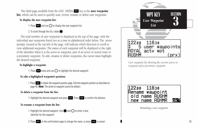
Renaming a user waypoint.
User waypoint list showing the current active-towaypoint and a proximity waypoint.
SECTION
3WPT KEY
User WaypointList
The third page available from the GNC 300XL’s W key is the user waypointlist, which can be used to quickly scan, review, rename or delete user waypoints.
To display the user waypoint list:
1. Press W and use O to display the user waypoint list.
2. To scroll through the list, rotate K.
The total number of user waypoints is displayed at the top of the page, with theindividual user waypoints listed two at a time in alphabetical order below. The arrowprompt, located at the top left of the page, will indicate which direction to scroll toview additional waypoints. The status of each waypoint will be displayed to the rightof the identifier when it is the active-to waypoint, part of an active or stored route ora proximity waypoint. To edit, rename or delete waypoints, the cursor must highlightthe desired waypoint.
To highlight a waypoint:
1. Press C twice and use O to highlight the desired waypoint.
To edit a highlighted waypoint’s position:
1. Press E to obtain the waypoint position page. Edit the waypoint position as described onpage 49. (Note: The active-to waypoint cannot be edited.)
To delete a waypoint from the list:
1. Highlight the desired waypoint and press \. Press E to confirm the deletion.
To rename a waypoint from the list:
1. Highlight the desired waypoint. Use K and O to enter a new identifier for the waypoint.
2. Press E on the confirmation page to change the name, or press \ to cancel. 53
300xl manual 1/25/99 2:35 PM Page 53

WPT KEYWaypointComments
SECTION
3
Entering waypoint comments.
Waypoints with comments page
The last page available through the GNC 300XL’s W key is the waypoints withcomments page, which lists all waypoints that have a user comment. User com-ments may be added to 250 waypoints stored in the user or NavData® database, andallow you to note two lines of special information concerning a particular waypoint.
To enter user comments:
1. Enter the waypoint identifier from any waypoint page (see page 38), and press C toremove the cursor.
2. Rotate O to display the ‘comments’ page.
3. Press C twice and use O to highlight either the second or third line.
4. Use K and O to enter the comment.
5. Press E to accept, and repeat steps 4 and 5, if necessary, to enter information on theother line.
6. Press C to remove the cursor.
To view the ‘waypoints with comments’ list:
1. Press W and use O to display the ‘Wpts with comments’ page.
2. Use K to scroll through the list.
The GNC 300XL will display the waypoints with comments in alphabetical order,up to six waypoints at a time. The scrolling arrow prompt will indicate which direc-tion to scroll to view additional waypoints.
To view comments for a selected waypoint:
1. Highlight the desired waypoint and press E (or press \ and E to delete).
2. Rotate O to display any other available pages for the selected waypoint.54
300xl manual 1/25/99 2:35 PM Page 54
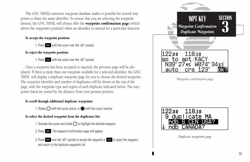
Duplicate waypoints page
Waypoint confirmation page
SECTION
3WPT KEY
Waypoint ConfirmationDuplicate Waypoints
The GNC 300XL’s extensive waypoint database makes it possible for several way-points to share the same identifier. To ensure that you are selecting the waypointdesired, the GNC 300XL will always offer the waypoint confirmation page (whichshows the waypoint’s position) when an identifier is entered for a particular function.
To accept the waypoint position:
1. Press E with the cursor over the ‘ok?’ prompt.
To reject the waypoint position:
1. Press \ with the cursor over the ‘ok?’ prompt.
Once a waypoint has been accepted or rejected, the previous page will be dis-played. If there is more than one waypoint available for a selected identifier, the GNC300XL will display a duplicate waypoint page for you to choose the desired waypoint.The waypoint identifier and number of duplicates will be shown at the top of thepage, with the waypoint type and region of each duplicate indicated below. The way-points listed are sorted by the distance from your present position.
To scroll through additional duplicate waypoints:
1. Rotate O with the cursor active, or K with the cursor inactive.
To select the desired waypoint from the duplicates list:
1. Activate the cursor and rotate O to highlight the desired waypoint.
2. Press E. The waypoint confirmation page will appear.
3. Press E over the ‘ok?’ prompt to accept the waypoint or \ to reject the waypointand return to the duplicate waypoints list.
55
300xl manual 1/25/99 2:35 PM Page 55

SECTION
3WPT KEY
Locked WaypointsWaypoint Scanning
Possible messages for locked waypoints.
To blank a waypoint field, highlight the field andpress the \ key.
Because the GNC 300XL relies on a NavData card for most waypoint information,there may be instances when waypoint information is not available for use. Lockedwaypoints exist when a waypoint contained in a route, used as a proximity waypointor with a comment is not contained on the NavData card, or no card is inserted inthe unit. If this condition exists, you’ll be alerted with a ‘Proximity wpt locked’,‘Route wpt locked’ or ‘Wpt comment locked’ message when the unit is powered up.The identifier of a locked waypoint will be replaced with a ‘lockd’ message, whichindicates you cannot obtain waypoint information or navigate to the waypoint. Theidentifier of a locked waypoint may be displayed by highlighting ‘lockd’ and pressingE. Locked waypoints may be deleted from routes, the proximity waypoints list orwaypoints with comments page by following the instructions in the appropriate section of this manual.
The waypoint scanning feature provides a fast way to scan through airports,VORs, NDBs and intersections in the database by identifier, facility name or city.Waypoint scanning may be used from any blank identifier field in the GPS window.
To enter a waypoint by scanning the identifier, facility name or city:
1. With the cursor over a blank identifier field, press W. If the identifier field is not blank,highlight the field with the cursor and press \ before pressing W.
2. Use O to highlight the waypoint category you wish to scan.
3. Press E to activate the scanning mode.
4. Rotate O to place the cursor over the field you want to scan (identifier, facility or cityname).
5. Use K and O to enter the letters of the identifier, city or facility name. The GNC 300XLwill scan the database and display the first waypoint that matches your entry.
6. Press E to accept the waypoint, and E again to confirm the waypoint for the function being used.56
300xl manual 1/25/99 2:35 PM Page 56

Nearest FSS page. To view additional frequencies(if available), highlight the frequency and rotatethe O knob.
Nearest airport with other frequency information.If an airport has multiple frequencies available,they may be quickly viewed without activating the cursor by pressing the \ key repeatedly.
SECTION
4NRST KEYOverview
Section 4 Nearest Waypoints
The GNC 300XL’s T key provides detailed information on the nine nearest airports,VORs, NDBs, intersections and user waypoints within 200 nm of your current position. Inaddition, it will display the two nearest Flight Service Station (FSS) and center (ARTCC/FIR) points of communication, plus alert you to any Special Use Airspace (SUA) you maybe in or near. The T key can be used in conjunction with the GNC 300XL’s direct-tofunction to quickly set a course to a nearby facility in case of an in-flight emergency.
To view the nearest waypoint information:
1. Press T.
This will display the nearest airport to your present position, subject to the runwaysurface type and minimum runway length selected (see page 105).
To scroll through the next eight nearest airports, rotate K.
You may examine both the communication frequencies and the runway informationdirectly from the nearest airport page. You may also place the displayed frequency intothe standby field by pressing E from the nearest airport page.
To view more comm/runway information:
1. Press C twice and rotate O to highlight the comm field or the runway field.
2. Rotate K to scroll through more information, if available.
To perform a direct-to on any of the nearest waypoint pages:
1. Press D. The waypoint confirmation page will appear.
2. Press E to accept the waypoint or \ to cancel.
57
300xl manual 1/25/99 2:35 PM Page 57

NOTE: The GNC 300XL will flash the U next to the M keyto inform you of SUA alerts. You do not have to repeatedlycheck the Nearest Waypoint page for SUA information. It isprovided to supply more information on the SUA and itsboundaries. The GNC 300XL will not flash alerts, however, ifit has been turned off or if your altitude is such that you willnot enter the buffered airspace. Turning off SUA alerts andsetting the altitude buffer is described on page 109.
SECTION
4NRST KEY
SpecialUse Airspace
The nearest waypoints for other categories (VORs, NDBs, etc.) may be viewed by rotating O. Rotating O continuously to the left will stop page selection on the nearest airport category.
The next page available under the GNC 300XL’s T key is the SUA (special-useairspace) alert page. The SUA alert page will alert you to as many as nine controlled orrestricted airspaces near or in your flight path, according to the following conditions:
• If your projected course will take you inside an SUA within the next 10 minutes, the message ‘SUA ahead < 10 min’ will be displayed.
• If you are within two nautical miles of an SUA and your current course will takeyou inside, the message ‘SUA Near & Ahead’ will be displayed.
• If you are within two nautical miles of an SUA and your current course will nottake you inside, the message ‘Near SUA < 2nm’ will be displayed.
• If you have entered an SUA, the message ‘Inside SUA’ will be displayed.
Note that the GNC 300XL’s SUA alerts are based on three-dimensional data (latitude,longitude and altitude) to avoid nuisance alerts. The alert boundaries for controlled air-space are also sectorized to provide complete information on any nearby airspace. Onceyou have met one of the described conditions, the message annunciator will flash, alert-ing you of an SUA message.
To view an SUA message:
1. Press the M key.
2. Press M again to return to the previous page.
Once you are notified of a SUA alert, detailed information concerning the specificSUA is provided by the T key.
58
Nearest SUA
Nearest SUA with controlling agency displayed.
300xl manual 1/25/99 2:35 PM Page 58

SECTION
4NRST KEY
SpecialUse Airspace
To view the SUA alert page:
1. Press the T key.
2. Rotate O one stop to the right to view the SUA alert page.
The SUA alert page contains the following information:
The ‘SUA number’ field displays which SUA you are viewing (you may be alerted to upto nine SUAs). SUAs are ranked with ‘sua1’ being the highest priority, and ‘sua9’ being thelowest priority from your current position. The ‘SUA alert’ field displays the correspondingalert message for this SUA, such as ‘near’, ‘near & ahead’, etc. (see page 58). The ETE (esti-mated time en route), located at the top right of the page, will only be displayed if you areprojected to enter the airspace.
The second line of the SUA alert page displays the name or controlling agency of theSUA, along with the type of SUA to which you are being alerted.
To toggle between the SUA name and controlling agency display:
1. Rotate K one stop in either direction.
If the SUA name or controlling agency is too long to fit on the display, the GNC 300XLwill automatically scroll to display the rest of the information. 59
SUA number
SUA Floor altitude
Alert type
Controlling airport identifier
SUA type
ETE(if applicable)
SUA Name orcontrolling
agency
SUA Ceiling altitude
300xl manual 1/25/99 2:35 PM Page 59

Frequency information for SUA. If the informa-tion is too long to fit on the display, the GNC300XL will automatically scroll to display the restof the information.
SUA alert page
SECTION
4NRST KEY
SUA Messages
The following SUA types can appear in the SUA type field:
Message Airspace Typealrt - Alertcaut - Cautioncl B - Class Bcl C - Class Ccta - ICAO Control Areadngr - Dangermoa - Military Operations Areaproh - Prohibitedrstc - Restrictedtma - ICAO Terminal Control Areatrng - Trainingtrsa - Terminal Radar Service Areaunsp - Unspecifiedwarn - Warning
The last line on the SUA alert page displays the SUA’s controlling airport identifierand the ceiling and floor altitudes for the SUA alert. Controlling agency frequenciesmay be viewed by highlighting the controlling airport identifier with the cursor andpressing E. The following are examples of what can appear in the altitude fields:
Message Meaning8000ftM - 8000 feet mean sea level (MSL)3000ftA - 3000 feet above ground level (AGL)ground - Ground levelmsl - Mean sea levelnotam - See Notice to Airmen (NOTAM)
for altitude restrictionsnot sp - Altitude is not specifiedunlmtd - Altitude is unlimited60
300xl manual 1/25/99 2:35 PM Page 60
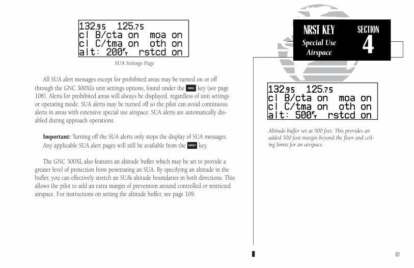
NRST KEYSpecial Use
Airspace
SECTION
4
Altitude buffer set at 500 feet. This provides anadded 500 foot margin beyond the floor and ceil-ing limits for an airspace.
All SUA alert messages except for prohibited areas may be turned on or offthrough the GNC 300XL’s unit settings options, found under the M key (see page108). Alerts for prohibited areas will always be displayed, regardless of unit settingsor operating mode. SUA alerts may be turned off so the pilot can avoid continuousalerts in areas with extensive special use airspace. SUA alerts are automatically dis-abled during approach operations.
Important: Turning off the SUA alerts only stops the display of SUA messages.Any applicable SUA alert pages will still be available from the T key.
The GNC 300XL also features an altitude buffer which may be set to provide agreater level of protection from penetrating an SUA. By specifying an altitude in thebuffer, you can effectively stretch an SUA’s altitude boundaries in both directions. Thisallows the pilot to add an extra margin of prevention around controlled or restrictedairspace. For instructions on setting the altitude buffer, see page 109.
61
SUA Settings Page
300xl manual 1/25/99 2:35 PM Page 61
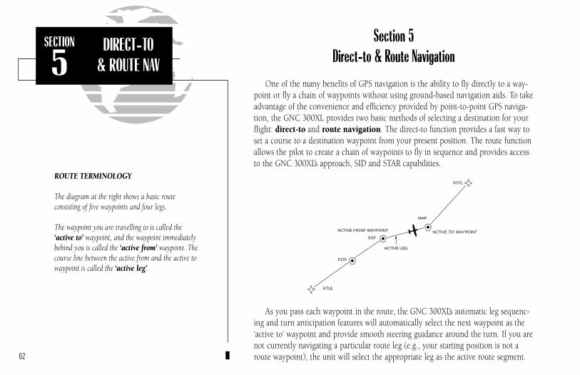
SECTION
5DIRECT-TO
& ROUTE NAV
Section 5 Direct-to & Route Navigation
One of the many benefits of GPS navigation is the ability to fly directly to a way-point or fly a chain of waypoints without using ground-based navigation aids. To takeadvantage of the convenience and efficiency provided by point-to-point GPS naviga-tion, the GNC 300XL provides two basic methods of selecting a destination for yourflight: direct-to and route navigation. The direct-to function provides a fast way toset a course to a destination waypoint from your present position. The route functionallows the pilot to create a chain of waypoints to fly in sequence and provides accessto the GNC 300XL’s approach, SID and STAR capabilities.
As you pass each waypoint in the route, the GNC 300XL’s automatic leg sequenc-ing and turn anticipation features will automatically select the next waypoint as the‘active to’ waypoint and provide smooth steering guidance around the turn. If you arenot currently navigating a particular route leg (e.g., your starting position is not aroute waypoint), the unit will select the appropriate leg as the active route segment.62
ROUTE TERMINOLOGY
The diagram at the right shows a basic route consisting of five waypoints and four legs.
The waypoint you are travelling to is called the ‘active to’ waypoint, and the waypoint immediatelybehind you is called the ‘active from’ waypoint. Thecourse line between the active from and the active towaypoint is called the ‘active leg’.
ACTIVE LEG
EOS
KTUL
SGF
KSTL
'ACTIVE FROM' WAYPOINT 'ACTIVE TO' WAYPOINT
MAP
300xl manual 1/25/99 2:35 PM Page 62
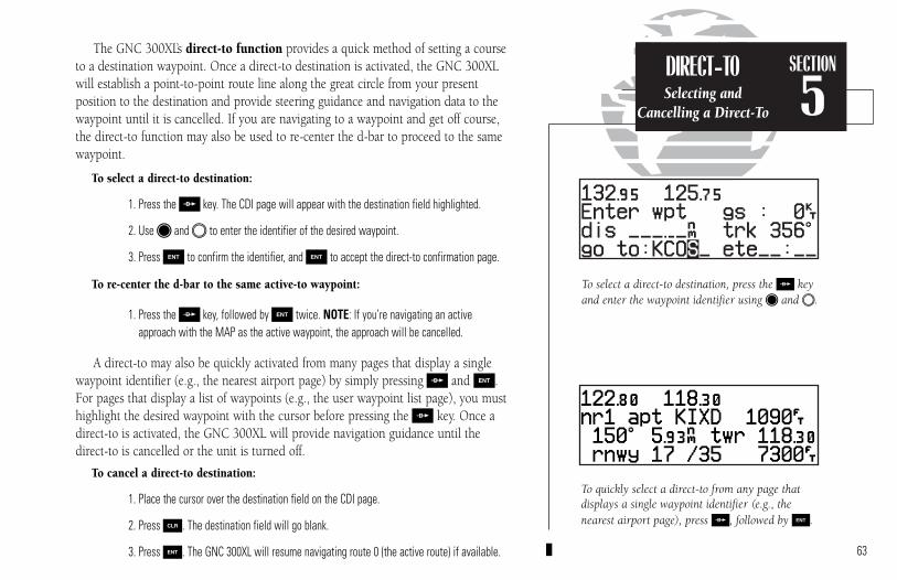
To quickly select a direct-to from any page thatdisplays a single waypoint identifier (e.g., thenearest airport page), press D, followed by E.
To select a direct-to destination, press the D keyand enter the waypoint identifier using K and O.
The GNC 300XL’s direct-to function provides a quick method of setting a courseto a destination waypoint. Once a direct-to destination is activated, the GNC 300XLwill establish a point-to-point route line along the great circle from your present position to the destination and provide steering guidance and navigation data to the waypoint until it is cancelled. If you are navigating to a waypoint and get off course,the direct-to function may also be used to re-center the d-bar to proceed to the samewaypoint.
To select a direct-to destination:
1. Press the D key. The CDI page will appear with the destination field highlighted.
2. Use K and O to enter the identifier of the desired waypoint.
3. Press E to confirm the identifier, and E to accept the direct-to confirmation page.
To re-center the d-bar to the same active-to waypoint:
1. Press the D key, followed by E twice. NOTE: If you’re navigating an activeapproach with the MAP as the active waypoint, the approach will be cancelled.
A direct-to may also be quickly activated from many pages that display a singlewaypoint identifier (e.g., the nearest airport page) by simply pressing D and E.For pages that display a list of waypoints (e.g., the user waypoint list page), you musthighlight the desired waypoint with the cursor before pressing the D key. Once adirect-to is activated, the GNC 300XL will provide navigation guidance until thedirect-to is cancelled or the unit is turned off.
To cancel a direct-to destination:
1. Place the cursor over the destination field on the CDI page.
2. Press \. The destination field will go blank.
3. Press E. The GNC 300XL will resume navigating route 0 (the active route) if available.
DIRECT-TOSelecting and
Cancelling a Direct-To
SECTION
5
63
300xl manual 1/25/99 2:35 PM Page 63
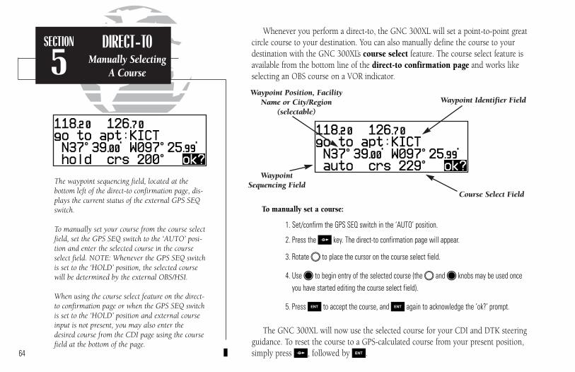
SECTION
5DIRECT-TO
Manually SelectingA Course
The waypoint sequencing field, located at the bottom left of the direct-to confirmation page, dis-plays the current status of the external GPS SEQswitch.
To manually set your course from the course selectfield, set the GPS SEQ switch to the ‘AUTO’ posi-tion and enter the selected course in the courseselect field. NOTE: Whenever the GPS SEQ switchis set to the ‘HOLD’ position, the selected coursewill be determined by the external OBS/HSI.
When using the course select feature on the direct-to confirmation page or when the GPS SEQ switchis set to the ‘HOLD’ position and external courseinput is not present, you may also enter thedesired course from the CDI page using the coursefield at the bottom of the page.
Whenever you perform a direct-to, the GNC 300XL will set a point-to-point greatcircle course to your destination. You can also manually define the course to yourdestination with the GNC 300XL’s course select feature. The course select feature isavailable from the bottom line of the direct-to confirmation page and works likeselecting an OBS course on a VOR indicator.
To manually set a course:
1. Set/confirm the GPS SEQ switch in the ‘AUTO’ position.
2. Press the D key. The direct-to confirmation page will appear.
3. Rotate O to place the cursor on the course select field.
4. Use K to begin entry of the selected course (the O and K knobs may be used onceyou have started editing the course select field).
5. Press E to accept the course, and E again to acknowledge the ‘ok?’ prompt.
The GNC 300XL will now use the selected course for your CDI and DTK steeringguidance. To reset the course to a GPS-calculated course from your present position,simply press D, followed by E.64
Waypoint Sequencing Field
Waypoint Identifier FieldWaypoint Position, Facility
Name or City/Region (selectable)
Course Select Field
300xl manual 1/25/99 2:35 PM Page 64

SECTION
5ROUTE NAVRoute Pages
The GNC 300XL lets you create up to 20 routes (numbered 0 through 19), withup to 31 waypoints each. Routes are created, copied and edited through the R key,which features five route pages selectable from the GNC 300XL’s outer knob.
The five route pages can be divided into two types: active route pages and aroute catalog page. Active route pages provide information and editing functions forroute 0, which always serves as the route you are currently navigating. The route cata-log page serves as the main page for creating, editing, activating, deleting and copyingall routes.
Routes 1-19 are used as storage routes, which are stored in the GNC 300XL’s inter-nal memory. Once a storage route is ‘activated’, a copy is placed into route 0 for navi-gation until it is cancelled, overwritten by activating another route or erased when theunit is turned off. If you want to save a route currently in route 0, be sure to copy itto an open storage route (routes 1-19) before it is cancelled, overwritten or erased.
65
Approach Select Page
Active Route Page
Route Catalog Page
SID Select Page STAR Select Page
REMEMBER!If you want to save the active route, be sure tocopy it to an empty storage route (1-19) beforeturning the GNC 300XL off or activating a newroute (or direct-to destination). See page 69 forinstructions on copying routes.
300xl manual 1/25/99 2:35 PM Page 65
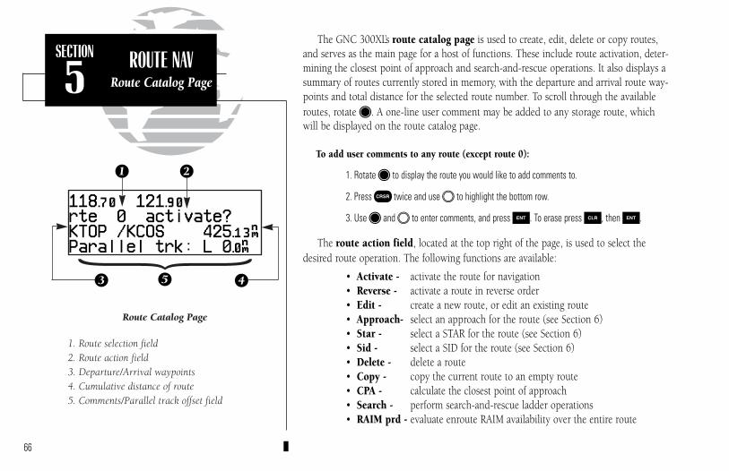
SECTION
5ROUTE NAV
Route Catalog Page
The GNC 300XL’s route catalog page is used to create, edit, delete or copy routes,and serves as the main page for a host of functions. These include route activation, deter-mining the closest point of approach and search-and-rescue operations. It also displays asummary of routes currently stored in memory, with the departure and arrival route way-points and total distance for the selected route number. To scroll through the availableroutes, rotate K. A one-line user comment may be added to any storage route, whichwill be displayed on the route catalog page.
To add user comments to any route (except route 0):
1. Rotate K to display the route you would like to add comments to.
2. Press C twice and use O to highlight the bottom row.
3. Use K and O to enter comments, and press E. To erase press \, then E.
The route action field, located at the top right of the page, is used to select thedesired route operation. The following functions are available:
• Activate - activate the route for navigation• Reverse - activate a route in reverse order• Edit - create a new route, or edit an existing route• Approach- select an approach for the route (see Section 6)• Star - select a STAR for the route (see Section 6)• Sid - select a SID for the route (see Section 6)• Delete - delete a route• Copy - copy the current route to an empty route• CPA - calculate the closest point of approach• Search - perform search-and-rescue ladder operations• RAIM prd - evaluate enroute RAIM availability over the entire route
66
21
453
Route Catalog Page
1. Route selection field2. Route action field3. Departure/Arrival waypoints4. Cumulative distance of route5. Comments/Parallel track offset field
{300xl manual 1/25/99 2:35 PM Page 66

SECTION
5ROUTE NAVCreating &
Editing Routes
The route editing function allows you to create new routes and edit existing routes.Creating routes before takeoff can help make route operations faster and easier duringyour flight.
To create or edit a route from the route catalog page:
1. Use K to display the route number you would like to edit.
2. Press C twice.
3. Use K to select ‘edit?’. Press E. The route review page will appear.
To add a waypoint:
4. Rotate O to highlight the first blank waypoint field or the point where you want to enterthe new waypoint. The first waypoint field will already be highlighted if you’re creating anew route.
5. Use K and O to enter the waypoint’s identifier. Press E.
6. Press E to confirm the ‘ok?’ prompt on the waypoint confirmation page.
7. Repeat steps 4 through 6 to add the next waypoint, or press C to finish.
To delete a waypoint:
1. Rotate O to highlight the waypoint you wish to delete.
2. Press \ to remove the name, then press E to delete.
3. Repeat steps 1 and 2 to delete additional waypoints, or press C to finish.
To delete an entire route:
1. Use K to display the route number you would like to delete (route 0 for the active route).
2. Press C twice and use O to highlight the action field.
3. Use K to select ‘delete?’. Press E to delete.
Selecting the route edit function.
Adding a waypoint to route 2.
67
300xl manual 1/25/99 2:35 PM Page 67
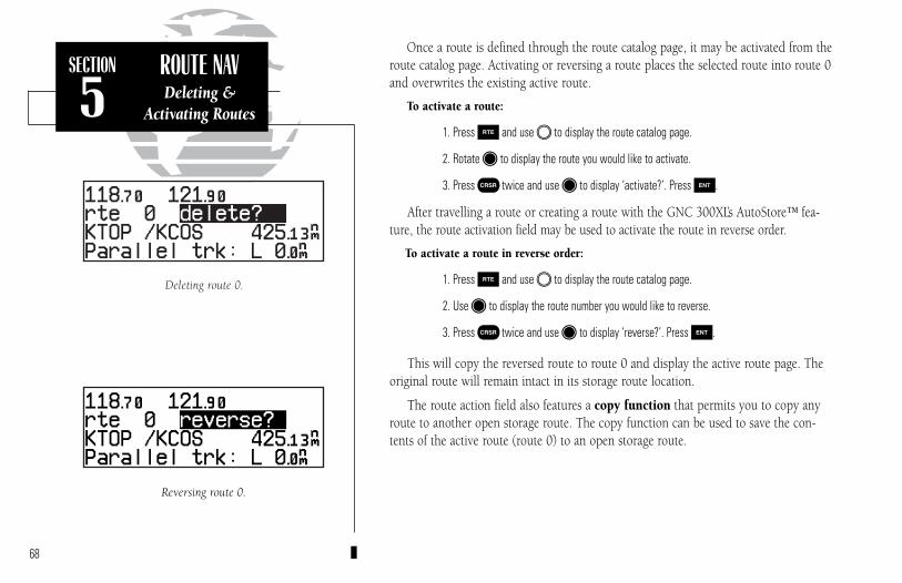
SECTION
5ROUTE NAVDeleting &
Activating Routes
Once a route is defined through the route catalog page, it may be activated from theroute catalog page. Activating or reversing a route places the selected route into route 0and overwrites the existing active route.
To activate a route:
1. Press R and use O to display the route catalog page.
2. Rotate K to display the route you would like to activate.
3. Press C twice and use K to display ‘activate?’. Press E.
After travelling a route or creating a route with the GNC 300XL’s AutoStore™ fea-ture, the route activation field may be used to activate the route in reverse order.
To activate a route in reverse order:
1. Press R and use O to display the route catalog page.
2. Use K to display the route number you would like to reverse.
3. Press C twice and use K to display ‘reverse?’. Press E.
This will copy the reversed route to route 0 and display the active route page. Theoriginal route will remain intact in its storage route location.
The route action field also features a copy function that permits you to copy anyroute to another open storage route. The copy function can be used to save the con-tents of the active route (route 0) to an open storage route.
68
Reversing route 0.
Deleting route 0.
300xl manual 1/25/99 2:35 PM Page 68

SECTION
5ROUTE NAV
Copying RoutesCPA Function
To copy a route:
1. Press R and use O to display the route catalog page.
2. Use K to display the route to which you would like to copy to. The route must be empty.
3. Press C twice and rotate K to select ‘copy?’. Press E.
4. Use K to enter the route you would like to copy. The departure/arrival identifiers will bedisplayed for your reference. Press E to copy the route.
The CPA function calculates the closest distance that a route will pass to a refer-ence waypoint, and helps when creating new route waypoints referenced to a NAVAID.
To calculate the closest point of approach (CPA) from the route catalog page:
1. Use K to display the route you would like to use for the CPA function. The route must consist of at least two waypoints, and the reference facility must fall between the waypoints of a route leg.
2. Press C twice and rotate K to select ‘cpa?’. Press E.
3. Use K and O to enter the identifier of the reference waypoint.
4. Press E. The bearing and distance of the closest point on the route will be displayed.
5. Press E to add the cpa waypoint to the route, or \ to finish. If you do add the cpawaypoint to the route, it will be named based on the reference waypoint plus a number (0-9) added to the end (e.g., KMCI3 for KMCI). If the waypoint does not fall between way-points on the route, the reference waypoint does not exist or a unique name cannot beassigned to the CPA waypoint, you’ll be informed with the ‘Invald CPA wpt ____’ message.
69
Calculating closest point of approach.
Closest point of approach to ‘TXK’.
300xl manual 1/25/99 2:35 PM Page 69
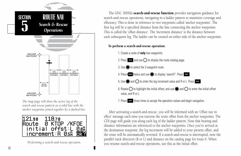
The GNC 300XL’s search-and-rescue function provides navigation guidance forsearch-and-rescue operations, navigating in a ladder pattern to maximize coverage andefficiency. This is done in reference to two waypoints called ‘anchor waypoints’. Thefirst leg will be a specified distance from the line connecting the anchor waypoints.This is called the ‘offset distance’. The ‘increment distance’ is the distance betweeneach subsequent leg. The ladder can be created on either side of the anchor waypoints.
To perform a search-and-rescue operation:
1. Create a route of only two waypoints.
2. Press R and use O to display the route catalog page.
3. Use K to select the 2-waypoint route.
4. Press C twice and use K to display ‘search?’. Press E.
5. Use K and O to enter the leg increment value and R or L. Press E.
6. Rotate O to highlight the initial offset, and use K and O to enter the initial offsetvalue, and R or L.
7. Press E three times to accept the operation values and begin navigation.
After activating a search-and-rescue, you will be informed with an ‘Offset nav ineffect’ message each time you traverse the route offset from the anchor waypoints. TheCDI page will guide you along each leg of the ladder pattern. Note that bearing anddistance information are referenced to the anchor waypoints. Once you’ve arrived atthe destination waypoint, the leg increment will be added to your present offset, andthe route will be automatically reversed. If a search-and-rescue is interrupted, note theparallel track direction (R or L) and distance on the catalog page for route 0. Whenyou resume search-and-rescue operations, use this as the initial offset.
SECTION
5ROUTE NAV
Search & RescueOperations
70
Performing a search-and-rescue operation.
The map page will show the active leg of thesearch and rescue pattern as a solid line with theanchor waypoints joined together by a dashed line.
300xl manual 1/25/99 2:35 PM Page 70

The GNC 300XL’s Route RAIM Prediction Function evaluates enroute RAIM availabil-ity over the entire route that the pilot intends to fly. Route RAIM Prediction ensuresthat satellite coverage will be sufficient to meet the protection limits defined byBRNAV/RNP-5 (FAA Advisory Circular 90-96).
To use the Route RAIM Prediction Function:
1. From the Route Catalog Page (Figure 1), select the desired route for RAIM prediction (if theroute is empty, enter the route first).
2. Highlight the route action field by pressing C twice, rotate K to select ‘RAIM prd?’and press E. The Route RAIM Prediction Page will be displayed (Figure 2).
3. Highlight and enter departure time, departure date, enroute altitude, and enroute groundspeed (valid enroute ground speed is “65 nm or greater”). Press E to accept.
4. When all parameters are properly entered, move the cursor to the ‘Compute?’ field, andpress E. The unit will start to predict the RAIM availability over the entire route, andwill switch to ‘WAIT ->’, with the arrow sign continually rotating, indicating that the pre-diction computation is in progress.
5. If RAIM is available for the entire route ‘RAIM OK’ will appear on the Route RAIMPrediction Page, as shown in Figure 3 (pg. 72).
71
SECTION
5ROUTE NAV Route RAIM Prediction
Figure 2
Figure 1
300xl manual 1/25/99 2:35 PM Page 71
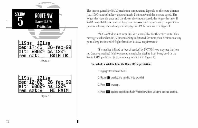
The time required for RAIM prediction computation depends on the route distance(i.e., 1000 nautical miles = approximately 2 minutes) and the enroute speed. Thelonger the route distance and the slower the enroute speed, the longer the time. IfRAIM unavailability is detected based on the associated requirement, the predictionprocess will stop immediately and display ‘NO RAIM’ as shown in Figure 4.
‘NO RAIM’ does not mean RAIM is unavailable for the entire route. Thismessage results when RAIM unavailability is detected for more than 5 minutes at anypoint along the intended flight (based on BRNAV requirements).
If a satellite is listed as ‘out of service’ by NOTAM, you may use the ‘remsat’ (remove satellite) field to prevent a particular satellite from being used in theRoute RAIM prediction (e.g., removing satellite 9 in Figure 4).
To exclude a satellite from the Route RAIM prediction:
1. Highlight the ‘rem sat’ field.
2. Rotate K to select the satellite to be excluded.
3. Press E to accept.
4. Press E again to begin Route RAIM Prediction without using the selected satellite.
72
SECTION
5ROUTE NAVRoute RAIMPrediction
Figure 4
Figure 3
300xl manual 1/25/99 2:35 PM Page 72

During route navigation, it is sometimes desirable to navigate a specified distanceaway from the ‘active leg’ to help avoid certain airspaces or regions. The GNC 300XL’sparallel track feature will automatically guide you along a selected offset from theactive leg. Bearing and distance information will be to the waypoints along the originalcourse, with the CDI (on the CDI page) centered on the offset course.
To use offset navigation, or ‘parallel track’:
1. Press R and use O to display the route catalog page.
2. Use K to display route 0 (parallel track can only be used on the active route).
3. Press C twice and use O to highlight the parallel track value field.
4. Use K and O to enter the desired distance and direction (R or L) from the leg.
5. Press E to accept. The map page will display the offset route as a solid line and the original route as a dashed line.
It is important to note that offset navigation is only available on route navigation,not direct-to navigation. If an approach is present in the active route, parallel offsetnavigation is cancelled when entering the 30 nm terminal area. Offset navigation isNOT valid for IFR approach procedures. “Approach not active” message will display ifparallel navigation is re-instated after approach navigation has been armed. When off-set navigation is activated, an ‘Offset nav in effect’ message will be displayed with thedistance and direction noted on the route catalog page for route 0. If you enter an off-set which causes a leg to be reversed, you’ll be informed with the message ‘Ofst toobig for rte’. If you change the active route in any way or perform a direct-to, you’ll beinformed with an ‘Offset nav cancelled’ message.
SECTION
5ROUTE NAV
Parallel TrackOffset Navigation
73
Parallel Track
Enter parallel track value after route activation.
300xl manual 1/25/99 2:35 PM Page 73
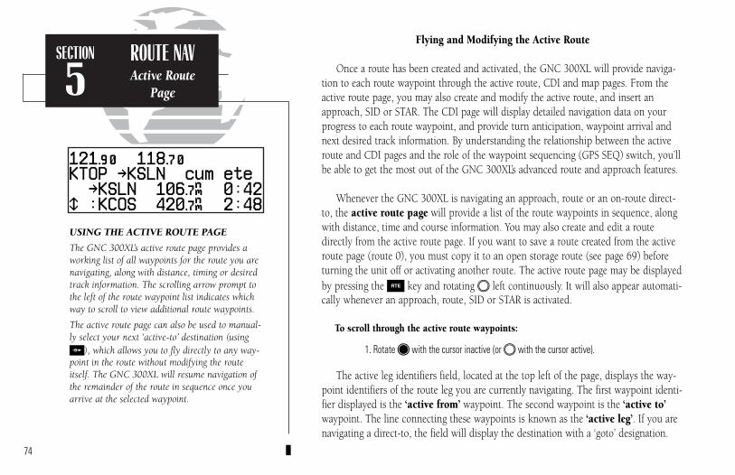
SECTION
5ROUTE NAVActive Route
Page
Flying and Modifying the Active Route
Once a route has been created and activated, the GNC 300XL will provide naviga-tion to each route waypoint through the active route, CDI and map pages. From theactive route page, you may also create and modify the active route, and insert anapproach, SID or STAR. The CDI page will display detailed navigation data on yourprogress to each route waypoint, and provide turn anticipation, waypoint arrival andnext desired track information. By understanding the relationship between the activeroute and CDI pages and the role of the waypoint sequencing (GPS SEQ) switch, you’llbe able to get the most out of the GNC 300XL’s advanced route and approach features.
Whenever the GNC 300XL is navigating an approach, route or an on-route direct-to, the active route page will provide a list of the route waypoints in sequence, alongwith distance, time and course information. You may also create and edit a routedirectly from the active route page. If you want to save a route created from the activeroute page (route 0), you must copy it to an open storage route (see page 69) beforeturning the unit off or activating another route. The active route page may be displayedby pressing the R key and rotating O left continuously. It will also appear automati-cally whenever an approach, route, SID or STAR is activated.
To scroll through the active route waypoints:
1. Rotate K with the cursor inactive (or O with the cursor active).
The active leg identifiers field, located at the top left of the page, displays the way-point identifiers of the route leg you are currently navigating. The first waypoint identi-fier displayed is the ‘active from’ waypoint. The second waypoint is the ‘active to’waypoint. The line connecting these waypoints is known as the ‘active leg’. If you arenavigating a direct-to, the field will display the destination with a ‘goto’ designation.
74
USING THE ACTIVE ROUTE PAGE
The GNC 300XL’s active route page provides aworking list of all waypoints for the route you arenavigating, along with distance, timing or desiredtrack information. The scrolling arrow prompt tothe left of the route waypoint list indicates whichway to scroll to view additional route waypoints.
The active route page can also be used to manual-ly select your next ‘active-to’ destination (usingD), which allows you to fly directly to any way-point in the route without modifying the routeitself. The GNC 300XL will resume navigation ofthe remainder of the route in sequence once youarrive at the selected waypoint.
300xl manual 1/25/99 2:35 PM Page 74
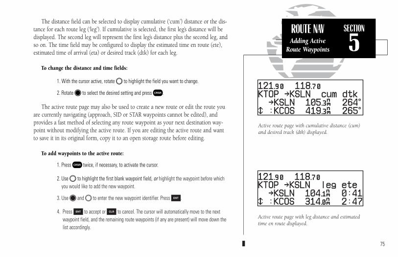
ROUTE NAVAdding Active
Route Waypoints
SECTION
5The distance field can be selected to display cumulative (‘cum’) distance or the dis-
tance for each route leg (‘leg’). If cumulative is selected, the first leg’s distance will bedisplayed. The second leg will represent the first leg’s distance plus the second leg, andso on. The time field may be configured to display the estimated time en route (ete),estimated time of arrival (eta) or desired track (dtk) for each leg.
To change the distance and time fields:
1. With the cursor active, rotate O to highlight the field you want to change.
2. Rotate K to select the desired setting and press C.
The active route page may also be used to create a new route or edit the route youare currently navigating (approach, SID or STAR waypoints cannot be edited), andprovides a fast method of selecting any route waypoint as your next destination way-point without modifying the active route. If you are editing the active route and wantto save it in its original form, copy it to an open storage route before editing.
To add waypoints to the active route:
1. Press C twice, if necessary, to activate the cursor.
2. Use O to highlight the first blank waypoint field, or highlight the waypoint before whichyou would like to add the new waypoint.
3. Use K and O to enter the new waypoint identifier. Press E.
4. Press E to accept or \ to cancel. The cursor will automatically move to the nextwaypoint field, and the remaining route waypoints (if any are present) will move down thelist accordingly.
75
Active route page with cumulative distance (cum)and desired track (dtk) displayed.
Active route page with leg distance and estimatedtime en route displayed.
300xl manual 1/25/99 2:35 PM Page 75

SECTION
5ROUTE NAV
On-RouteDirect-To
To delete a waypoint from the active route:
1. Press C twice, if necessary, to activate the cursor.
2. Use O to highlight the waypoint you would like to delete from the active route.
3. Press \, followed by E. The next route waypoint (if available) will move up to takethe position of the deleted waypoint.
The active route page also allows you to select your next destination waypointmanually from the active route waypoint list and resume the remainder of the routein sequence. This procedure, referred to as an ‘on-route’ direct-to, allows the pilotto fly directly to any waypoint in the active route without editing the active route,approach, SID or STAR itself. For example, if you are flying a route with an armedapproach, the GNC 300XL will automatically provide the initial approach fix (IAF)for the selected approach as your ‘active to’ waypoint. If you have been vectoreddirectly to the final approach fix (bypassing the IAF), you can manually “skip ahead”to the final approach fix as your next active to waypoint.
To perform an on-route direct-to from the active route page:
1. Press C twice and rotate O to highlight the desired waypoint.
2. Press D, followed by E to confirm the ‘ok?’ prompt on the waypoint confirmation page.
The GNC 300XL will now provide guidance to the selected waypoint and resumenavigating the remainder of the route in sequence once you arrive at the next destina-tion waypoint. The waypoint sequencing field, located at the bottom left of thedirect-to confirmation page, indicates the current status of the waypoint sequencing(GPS SEQ) switch. For more information on the waypoint sequencing switch andwaypoint ‘hold’ operations, see Section 6.76
You can hold on a destination waypoint by settingthe GPS SEQ switch to the ‘HOLD’ position. TheGNC 300XL will hold on the current ‘active to’waypoint as your navigation reference and pre-vents the unit from sequencing to the next way-point in the route. A user-defined course may alsobe selected on the external HSI (OBS).
Whenever waypoint sequencing is set to ‘hold’, thedesired course is displayed at the bottom left of theCDI page. See page 64 for more details.
300xl manual 1/25/99 2:35 PM Page 76

SECTION
5ROUTE NAVTurn Anticipation
During route operations, the CDI page is used to provide turn anticipation, nextdesired track and waypoint arrival information to the pilot. The GNC 300XL’s turnanticipation feature will smooth out the transition between adjacent route legs by pro-viding CDI guidance along a curved path segment. This leg transition is based on the air-craft’s actual ground speed and the difference between the course angle of the two legs.The GNC 300XL will automatically sequence to the next leg when you are abeam the‘active to’ waypoint on the curved transition segment, and the to/from indicator on theCDI will flip momentarily. During the transition, the CDI display will be referenced tothe dotted line illustrated at the right. Turn anticipation will not be provided in the following scenarios:
• Waypoint/fix crossing is a requirement of the approach, SID or STAR you’re navigating.
• The GPS SEQ switch is in the HOLD position.
• Your current ground speed and the course angle between the two legsrequire a bank angle greater than 25º (see right).
As you approach a route waypoint, the GNC 300XL’s external waypoint annunciatorwill flash 15 seconds before the turn anticipation point, and the graphical CDI on theCDI page will be replaced by a flashing ‘Next dtk xxxº’ prompt (and the desired trackreadout on the map page will flash), indicating the desired track of the next route leg.
To use the turn anticipation feature, note the ‘Nxt dtk’ heading when the externalwaypoint annunciator begins to flash, and start the turn when the annunciator glowssteadily (approximately 2 seconds before the turn anticipation point). Once you’vereached the turn anticipation point, the desired track (dtk) field on the CDI page willchange to display the course for the next leg. If you have not adjusted your HSI courseselector before the turn, the ‘Next dtk’ will continue to flash until you have reached themidpoint of the turn. Please refer to your aircraft flight manual supplement for specificturn anticipation instructions.
Since the approach select, STAR select and SID select pages relate to the GNC300XL’s approach features, these pages and their functions are described in Section 6.
If the turn angle and your present speed willrequire a bank angle that exceeds 25º, you’ll benotified with a ‘Steep turn ahead’ messageapproximately 90 seconds before arrival at theactive to waypoint.
As you approach a route waypoint, the graphicalCDI will be replaced by a flashing ‘Next dtk xxxº’prompt indicating the desired track of the next leg.When using the map page, the desired track read-out will flash and indicate the dtk for the next leg.
77
300xl manual 1/25/99 2:35 PM Page 77
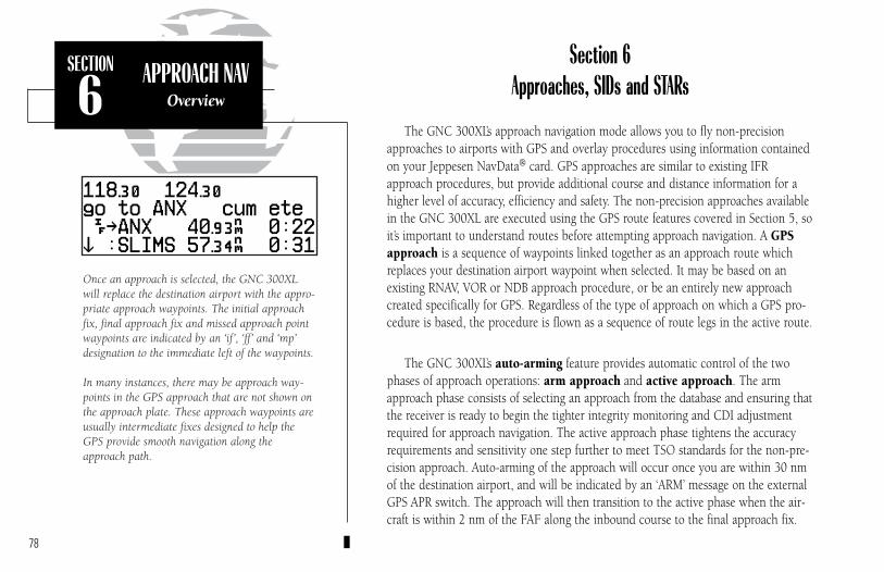
SECTION
6APPROACH NAV
Overview
Section 6Approaches, SIDs and STARs
The GNC 300XL’s approach navigation mode allows you to fly non-precisionapproaches to airports with GPS and overlay procedures using information containedon your Jeppesen NavData® card. GPS approaches are similar to existing IFRapproach procedures, but provide additional course and distance information for ahigher level of accuracy, efficiency and safety. The non-precision approaches availablein the GNC 300XL are executed using the GPS route features covered in Section 5, soit’s important to understand routes before attempting approach navigation. A GPSapproach is a sequence of waypoints linked together as an approach route whichreplaces your destination airport waypoint when selected. It may be based on anexisting RNAV, VOR or NDB approach procedure, or be an entirely new approachcreated specifically for GPS. Regardless of the type of approach on which a GPS pro-cedure is based, the procedure is flown as a sequence of route legs in the active route.
The GNC 300XL’s auto-arming feature provides automatic control of the twophases of approach operations: arm approach and active approach. The armapproach phase consists of selecting an approach from the database and ensuring thatthe receiver is ready to begin the tighter integrity monitoring and CDI adjustmentrequired for approach navigation. The active approach phase tightens the accuracyrequirements and sensitivity one step further to meet TSO standards for the non-pre-cision approach. Auto-arming of the approach will occur once you are within 30 nmof the destination airport, and will be indicated by an ‘ARM’ message on the externalGPS APR switch. The approach will then transition to the active phase when the air-craft is within 2 nm of the FAF along the inbound course to the final approach fix.
78
Once an approach is selected, the GNC 300XLwill replace the destination airport with the appro-priate approach waypoints. The initial approachfix, final approach fix and missed approach pointwaypoints are indicated by an ‘if’, ‘ff’ and ‘mp’designation to the immediate left of the waypoints.
In many instances, there may be approach way-points in the GPS approach that are not shown onthe approach plate. These approach waypoints areusually intermediate fixes designed to help theGPS provide smooth navigation along theapproach path.
300xl manual 1/25/99 2:35 PM Page 78

The GNC 300XL works in conjunction with a set of external switches and your HSI (OBS) to fly GPS approaches. The external switches are used to control GPS func-tions, and contain illuminated annunciators to indicate when functions are active. Yourinstallation must also have annunciators for waypoint arrival and GPS messages.
The NAV/GPS switch determines which data (GPS or NAV1) will be displayed onthe HSI and used by the autopilot/flight director. The current selection will be indi-cated by an annunciator light. If power to the GNC 300XL is lost, the system willautomatically revert to NAV1.
The GPS APR switch is used to arm or deactivate an approach, and indicates thecurrent approach phase status (‘ARM’ or ‘ACTV’). The GNC 300XL will automati-cally arm a selected approach 30 nm from the airport. If the pilot wishes to termi-nate the approach or fly the missed approach, the GPS APR switch may be pressedto disarm/deactivate the approach at any time and return the CDI scale sensitivityto the 1.0 nm setting. The GPS APR switch may also be used to re-arm theapproach at any time before reaching the FAF. If the selected approach is disarmedbefore the FAF, the unit will prompt you to re-arm the approach 3 nm before thefinal approach fix. 79
SECTION
6APPROACH NAVGPS APR Switch
Auto Arming
Arm Approach Mode
The external GPS APR switch will automaticallybe set to the ARM position 30 nm from the destina-tion airport. Once the approach is armed, the unitwill provide a smooth transition from the 5.0 to 1.0nautical mile CDI scale, and down to 0.3 nm with-in 2 nm inbound to the FAF. If the approach ismanually disarmed, it may be re-armed at anytime (before reaching the FAF) by pressing the GPSAPR switch.
GPS APRARM ACTV
GPS APRARM ACTV
NAV GPSNAV ACTV
NAV GPSARM GPS
GPS APRCTV
300xl manual 1/25/99 2:35 PM Page 79

The GPS SEQ switch is used to select manual or automatic waypoint sequencingof waypoints. Setting the GPS SEQ switch to the HOLD position holds your current‘active to’ waypoint as your navigation reference and prevents the GPS from sequenc-ing to the next waypoint. When the GPS SEQ switch is set to the AUTO position,automatic waypoint sequencing is selected. Whenever the GPS SEQ switch is engaged,the HOLD annunciator will illuminate and the GPS will continue navigating to theactive-to waypoint regardless of your position relative to other waypoints.
The GPS SEQ switch must be set to the HOLD position any time you are deviatingfrom the flight sequence of an approach (e.g., when you are flying radar vectors) orwhen you must cross the same waypoint twice in succession (e.g., procedure turn,IAF and FAF at the same waypoint). Whenever the GPS SEQ switch is set to theHOLD position, the GNC 300XL allows you to select the desired course to/from awaypoint using the HSI, much like a VOR.
Whenever the GPS SEQ switch is released from the HOLD position, the GNC300XL will ‘capture’ the present HSI setting as your desired course. Always dial inyour next desired course before returning the GPS SEQ switch to the AUTO position.The GPS SEQ switch may be released from the HOLD position 2 seconds after theinbound course has been set. The GNC 300XL will continue navigation on the lastselected course through the active-to waypoint and sequence to the next approach waypoint.
80
SECTION
6APPROACH NAVGPS SEQ Switch
GPS SEQAUTO ACTV
GPS SEQAUTO HOLD
Always set the desired course on the HSI (OBS)BEFORE returning the GPS SEQ switch to the‘AUTO’ position.
OBS
TO
FR
N33
30W
24
21 S15
12E
6
3
GPS SEQAUTO ACTV
300xl manual 1/25/99 2:35 PM Page 80
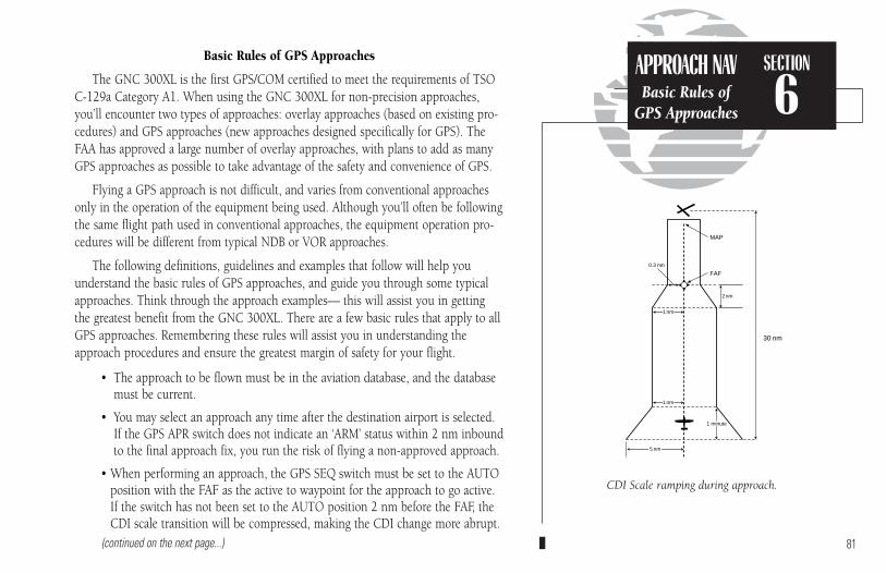
Basic Rules of GPS Approaches
The GNC 300XL is the first GPS/COM certified to meet the requirements of TSO C-129a Category A1. When using the GNC 300XL for non-precision approaches,you’ll encounter two types of approaches: overlay approaches (based on existing pro-cedures) and GPS approaches (new approaches designed specifically for GPS). TheFAA has approved a large number of overlay approaches, with plans to add as manyGPS approaches as possible to take advantage of the safety and convenience of GPS.
Flying a GPS approach is not difficult, and varies from conventional approachesonly in the operation of the equipment being used. Although you’ll often be followingthe same flight path used in conventional approaches, the equipment operation pro-cedures will be different from typical NDB or VOR approaches.
The following definitions, guidelines and examples that follow will help youunderstand the basic rules of GPS approaches, and guide you through some typicalapproaches. Think through the approach examples— this will assist you in gettingthe greatest benefit from the GNC 300XL. There are a few basic rules that apply to allGPS approaches. Remembering these rules will assist you in understanding theapproach procedures and ensure the greatest margin of safety for your flight.
• The approach to be flown must be in the aviation database, and the databasemust be current.
• You may select an approach any time after the destination airport is selected.If the GPS APR switch does not indicate an ‘ARM’ status within 2 nm inboundto the final approach fix, you run the risk of flying a non-approved approach.
• When performing an approach, the GPS SEQ switch must be set to the AUTOposition with the FAF as the active to waypoint for the approach to go active.If the switch has not been set to the AUTO position 2 nm before the FAF, theCDI scale transition will be compressed, making the CDI change more abrupt.
(continued on the next page...) 81
SECTION
6APPROACH NAVBasic Rules of
GPS Approaches
CDI Scale ramping during approach.
0.3 nm
30 nm
2nm
FAF
MAP
1 nm
1 nm
5 nm
1 minute
300xl manual 1/25/99 2:35 PM Page 81
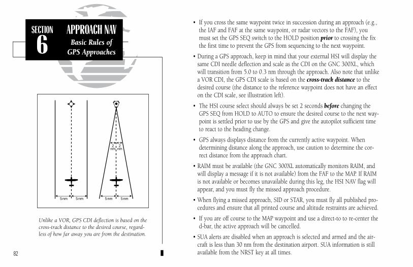
• If you cross the same waypoint twice in succession during an approach (e.g.,the IAF and FAF at the same waypoint, or radar vectors to the FAF), youmust set the GPS SEQ switch to the HOLD position prior to crossing the fixthe first time to prevent the GPS from sequencing to the next waypoint.
• During a GPS approach, keep in mind that your external HSI will display thesame CDI needle deflection and scale as the CDI on the GNC 300XL, whichwill transition from 5.0 to 0.3 nm through the approach. Also note that unlikea VOR CDI, the GPS CDI scale is based on the cross-track distance to thedesired course (the distance to the reference waypoint does not have an effecton the CDI scale, see illustration left).
• The HSI course select should always be set 2 seconds before changing theGPS SEQ from HOLD to AUTO to ensure the desired course to the next way-point is settled prior to use by the GPS and give the autopilot sufficient timeto react to the heading change.
• GPS always displays distance from the currently active waypoint. Whendetermining distance along the approach, use caution to determine the cor-rect distance from the approach chart.
• RAIM must be available (the GNC 300XL automatically monitors RAIM, andwill display a message if it is not available) from the FAF to the MAP. If RAIMis not available or becomes unavailable during this leg, the HSI NAV flag willappear, and you must fly the missed approach procedure.
• When flying a missed approach, SID or STAR, you must fly all published pro-cedures and ensure that all printed course and altitude restraints are achieved.
• If you are off course to the MAP waypoint and use a direct-to to re-center thed-bar, the active approach will be cancelled.
• SUA alerts are disabled when an approach is selected and armed and the air-craft is less than 30 nm from the destination airport. SUA information is stillavailable from the NRST key at all times.82
SECTION
6APPROACH NAV
Basic Rules ofGPS Approaches
Unlike a VOR, GPS CDI deflection is based on thecross-track distance to the desired course, regard-less of how far away you are from the destination.
5 nm5 nm 5 nm5 nm
2nm
2nm
300xl manual 1/25/99 2:35 PM Page 82

Flying A Typical Approach
The non-precision approaches available from the GNC 300XL will all follow thesame general flow of events described below. Specific details and instructions relatingto each step, along with several approach examples are provided later in this chapter.
1. Create a direct-to or route with an airport as the final destination
To save time during your flight, you may wish to create a route and selectan approach before takeoff using the route catalog page.
2. Select an approach for the destination airport
An approach may be selected at any time, but must be loaded before reach-ing the final approach fix. Once an approach is selected, the approach way-points will replace the destination airport and the GNC 300XL will providenavigation to the Initial Approach Fix.
3. Transition to the Arm Approach Phase
The GNC 300XL will automatically arm the approach 30 nm from the destination airport. The CDI scale will begin to ramp down from the 5.0nm to the 1.0 nm scale, and the GPS APR annunciator will indicate an‘ARM’ status.
4. Establish yourself on the final approach course
a. No procedure turn approach– no special requirementsb. Radar vectors– requires use of GPS SEQ switch to hold on
designated approach waypointc. Procedure turn– requires use of GPS SEQ switch to hold on
active waypointd. DME arc– requires use of position page to monitor distance from
reference waypoint(continued on the next page...) 83
SECTION
6APPROACH NAVTypical Approach
Procedures
GPS APRARM ACTV
GPS APRCTV
Select the approach.
The GNC 300XL will automatically arm theapproach 30 nm from the destination airport.
300xl manual 1/25/99 2:35 PM Page 83

5. Transition to Active Approach PhaseThe approach will automatically transition to the active approach stage andthe GPS APR annunciator will indicate an ‘ACTV’ status if the followingconditions are met:
a. The approach is armedb. The aircraft is 2 nm from the FAF on an inbound coursec. The GPS SEQ switch is set to the ‘AUTO’ positiond. The FAF is the active-to waypointe. The GNC 300XL confirms that integrity monitoring will be available to
complete the approach
Once the active approach phase begins, the CDI scale will begin to gradual-ly transition from the 1.0 nm scale to the 0.3 nm scale, and remain at the0.3 nm scale from the FAF to the MAP unless the approach is cancelled bypressing the external GPS APR switch, setting the GPS SEQ switch to‘HOLD’ or by initiating a direct-to operation.
WARNING: You are not authorized to fly the final portion of the approachunless the external GPS APR annunciator indicates an ‘ACTV’ status.
6. Missed Approach ProcedureThe GNC 300XL’s automatic waypoint sequencing stops at the missedapproach point. Once you have crossed the MAP, the GNC 300XL will giveyou the option of flying direct to the missed approach holding point:
a. Press the GPS APR switch to return the CDI to the 1.0 nm scale.b. AFTER crossing the MAP, press D, followed by E to fly directly to
the missed approach holding point.
WARNING! A direct course to the missed approach holding point may notcorrespond to the published missed approach procedure. Always fly allpublished procedures before selecting the holding fix on the GPS. 84
SECTION
6APPROACH NAVTypical Approach
Procedures
TSO C-129a requires that satellite coverage and navigational accuracy provided by the GPS systemmeet minimum standards. A ‘No RAIM from FAFto MAP’ message will appear if RAIM is predictedto be unavailable for an approach. If you receive aRAIM message, continue the approach ONLY if theACTV annunciator remains illuminated to theMAP. If the ACTV annunciator does not stay illu-minated, your HSI NAV flag will appear, and youmust fly the missed approach procedure.
GPS approaches must be in the current aviationdatabase to be approved.
300xl manual 1/25/99 2:35 PM Page 84

Selecting and Loading an Approach
When an arrival airport is selected with the direct-to key (or created and activated ina route to the arrival airport), the approaches for your arrival airport become availablethrough the approach select page, which can be viewed by pressing R and rotatingthe outer knob. Remember that an airport must be the last waypoint in a route to selectan approach.
To select an approach:
1. Select the destination airport using the D key, or create and activate a route to the destination airport (see Section 5).
2. Press R and rotate O to display the approach select page.
3. Rotate K (or O with the cursor active) to display the desired approach procedure.
4. Press C twice (if necessary) and rotate O until the desired approach is highlighted.
5. Press E to select the approach.
If an approach procedure has more than one Initial Approach Fix (IAF), you’ll needto select the desired IAF identifier for your approach.
To select an IAF:
1. Rotate O until the desired IAF is highlighted.
2. Press E.
Once the IAF is selected, the approach waypoints will be inserted into Route 0,replacing the destination airport, and the active route page will be displayed. To reviewthe active route, rotate the K knob. The scrolling arrow prompt will indicate whichdirection to scroll to view additional waypoints, while the ‘if’, ‘ff’ and ‘mp’ designatorswill indicate the IAF, FAF and MAP respectively. 85
SECTION
6APPROACH NAV
SelectingApproaches
Once the approach is loaded, the active route pagewill appear.
Select the Initial Approach Fix.
300xl manual 1/25/99 2:35 PM Page 85

When the aircraft is within 30 nautical miles of the destination airport, the GNC300XL will automatically arm the approach, and the GPS APR switch will indicate an‘ARM’ status.
To fly the GPS approach (without radar vectors):
1. Confirm that the GPS APR switch indicates an ‘ARM’ status. The CDI scale will begin asteady transition from the 5.0 nm to the 1.0 nm scale as you make your way to the FAF. Ifthe approach has been disarmed and the aircraft is within 3 nm of the FAF, the GNC 300XLwill prompt you to re-arm the approach.
2. The GNC 300XL will automatically sequence to each waypoint in the approach, with CDI, course and timing guidance to each waypoint. For each waypoint in the approach, the GNC300XL’s turn anticipation and waypoint alerting features will provide three pilot cues:
a. The waypoint annunciator will flash approximately 15 seconds before reaching theturning point for each approach waypoint, and glow steadily approximately 2 secondsprior to the turn anticipation point.
b. The ‘Next dtk’ prompt will flash in the CDI field when the ‘WPT’ annunciator beginsflashing. Set the HSI course select to the next dtk value when the waypoint annuncia-tor starts flashing. Start the turn when the annunciator glows steadily.
c. The To/From indicator flag on the GPS CDI will flip momentarily to indicate you havetransitioned to the next approach leg.
For more information on turn anticipation and waypoint alerting, please refer to Section 5.
3. If a procedure turn is required:a. 2 miles prior to crossing the waypoint outbound, set the GPS SEQ switch to HOLD.b. At the waypoint, set the outbound course on the HSI.
c. Fly the procedure turn. After the procedure turn outbound, set the inbound course onthe HSI.
d. On the inbound intercept to the final course, fly to center the CDI.(continued on next page)
86
SECTION
6APPROACH NAV
Flying theApproach
The ‘Next dtk’ prompt will flash to indicate thedesired course for the leg of the approach route.Set the HSI course select to the next dtk valuewhen the waypoint annunciator starts flashing.
The GPS APR switch will indicate ‘ARM’ when theapproach is armed. This will begin automatic CDIscale transitioning from 5.0 nm to 1.0 nm as youmake your way to the FAF.
300xl manual 1/25/99 2:35 PM Page 86
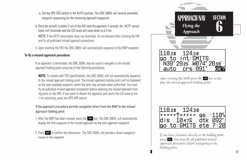
e. Set the GPS SEQ switch to the AUTO position. The GNC 300XL will resume automaticwaypoint sequencing for the remaining approach waypoints.
4. Once the aircraft is within 2 nm of the FAF (and the approach is armed), the ‘ACTV’ annun-ciator will illuminate and the CDI scale will ramp down to 0.3 nm.
NOTE: If the ACTV annunciator does not illuminate, do not descend after crossing the FAFand fly all published missed approach procedures.
5. Upon reaching the FAF, the GNC 300XL will automatically sequence to the MAP waypoint.
To fly a missed approach procedure:
If an approach is terminated, the GNC 300XL may be used to navigate to the missedapproach holding point using one of the following procedures.
NOTE: To comply with TSO specifications, the GNC 300XL will not automatically sequence to the missed approach holding point. The missed approach holding point will be displayedas the next available waypoint, which the pilot may activate when authorized. You mustfly all published missed approach procedures before selecting the missed approach hold-ing point on the GPS. If you want to disarm the approach and return the CDI scale to the 1 nm sensitivity, press the GPS APR switch.
If the approach procedure permits navigation direct from the MAP to the missedapproach holding point:
1. After the MAP has been crossed, press the D key. The GNC 300XL will automatically display the first waypoint of the missed approach as the next approach waypoint.
2. Press E to confirm the destination. The GNC 300XL will provide a direct navigationcourse to the waypoint.
87
If you have clearance directly to the holding point,press E. You must fly all published missedapproach procedures before navigating to the holding point.
After crossing the MAP, press the D key to dis-play the missed approach holding point.
SECTION
6APPROACH NAV
Flying the Approach
300xl manual 1/25/99 2:35 PM Page 87
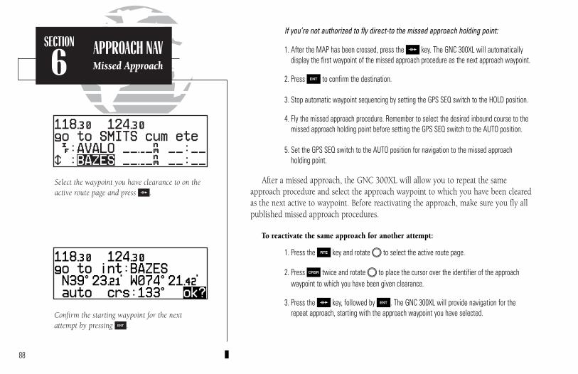
If you’re not authorized to fly direct-to the missed approach holding point:
1. After the MAP has been crossed, press the D key. The GNC 300XL will automaticallydisplay the first waypoint of the missed approach procedure as the next approach waypoint.
2. Press E to confirm the destination.
3. Stop automatic waypoint sequencing by setting the GPS SEQ switch to the HOLD position.
4. Fly the missed approach procedure. Remember to select the desired inbound course to themissed approach holding point before setting the GPS SEQ switch to the AUTO position.
5. Set the GPS SEQ switch to the AUTO position for navigation to the missed approach holding point.
After a missed approach, the GNC 300XL will allow you to repeat the sameapproach procedure and select the approach waypoint to which you have been clearedas the next active to waypoint. Before reactivating the approach, make sure you fly allpublished missed approach procedures.
To reactivate the same approach for another attempt:
1. Press the R key and rotate O to select the active route page.
2. Press C twice and rotate O to place the cursor over the identifier of the approachwaypoint to which you have been given clearance.
3. Press the D key, followed by E. The GNC 300XL will provide navigation for therepeat approach, starting with the approach waypoint you have selected.
88
Confirm the starting waypoint for the nextattempt by pressing E.
Select the waypoint you have clearance to on theactive route page and press D.
SECTION
6APPROACH NAVMissed Approach
300xl manual 1/25/99 2:35 PM Page 88

The GNC 300XL’s approach select page allows you to review the available approachprocedures at the destination airport. From the procedures list, you may select and activate anew procedure on the fly. The active approach is indicated by an on-screen asterisk, and thescrolling arrow prompt indicates which direction to scroll to view additional procedures.
To select or replace a procedure from the approach select page:
1. Press the R key and rotate O until the approach select page appears.
2. To review all available procedures, rotate K. “UNKN” (unknown) is displayed on theapproach select page when the unit software does not how to display a new approachtype in the database. DO NOT USE THIS APPROACH TYPE.
3. To select a procedure, press C twice and rotate O to highlight the desired procedure.
4. Press E. If there are multiple IAFs for the selected approach, rotate O to select thedesired IAF and press E.
You may also replace or delete the active approach from the route catalog page.
To replace or delete an approach from the route catalog page:
1. Press the R key and rotate O until the route catalog page appears.
2. Press C twice and rotate K until the ‘approach?’ prompt appears. Press E.
3. To replace the active approach procedure, rotate O to highlight the desired procedureand press E. If there are multiple IAFs for the selected approach, rotate O to selectthe desired IAF and press E.
4. To delete the active approach (denoted by an asterisk), highlight the approach and press\, followed by E.
89
The Approach Select Page after deleting the active approach. If direct-to navigation to aSID/STAR/Approach waypoint is active when the procedure is deleted, the direct-to waypoint will be retained as an “off route” destination.
Approach Select Page
SECTION
6APPROACH NAVApproach Select
Page
300xl manual 1/25/99 2:35 PM Page 89

GPS APPROACH EXAMPLES
In the examples that follow, the GPS waypoints are shown along the approachpath. In some cases, intermediate database waypoints have been added to approaches.These waypoints are named using lower case letters using the following convention(the most common database waypoints are defined below). Note that these waypointsare not charted on NOS approach plates. They do appear on current Jeppesenapproach charts.
• dyyyj— DME arc waypoint where yyy is the radial from thereference facility (VOR) and j represents the arcradius (e.g., “a”= 1 nm, “b”= 2 nm, etc.)
• cfxx or cfxxx— course fix for runway xx or radial xxx• ffxx or ffxxx— final approach fix for runway xx or radial xxx
• rwxx— runway xx threshold
• nxxhp— NDB approach runway xx intermediate holding pattern waypoint
• maxx or maxxx— missed approach point for runway xx or radial xxx
• vxxhp— VOR approach runway xx intermediate holding pattern waypoint
90
SECTION
6APPROACH NAV
GPS ApproachExamples
BAY CITYIAF
344 BYY
307°
10 NM
082°262°
MAGUS
307°
1800116° (7.9)
n13hp
ff13
387
Ref: NDB RWY 13 approachat Bay City TX (3R1)
300xl manual 1/25/99 2:35 PM Page 90
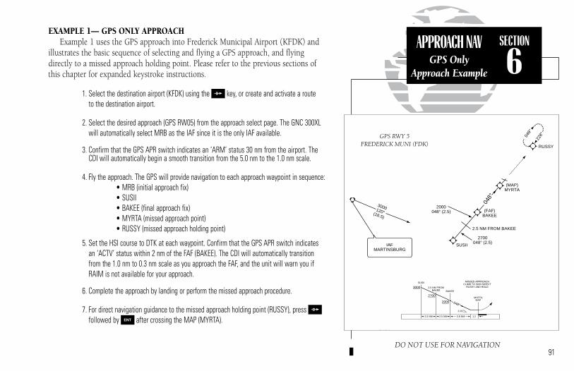
EXAMPLE 1— GPS ONLY APPROACHExample 1 uses the GPS approach into Frederick Municipal Airport (KFDK) and
illustrates the basic sequence of selecting and flying a GPS approach, and flyingdirectly to a missed approach holding point. Please refer to the previous sections ofthis chapter for expanded keystroke instructions.
1. Select the destination airport (KFDK) using the D key, or create and activate a route to the destination airport.
2. Select the desired approach (GPS RW05) from the approach select page. The GNC 300XL will automatically select MRB as the IAF since it is the only IAF available.
3. Confirm that the GPS APR switch indicates an ‘ARM’ status 30 nm from the airport. TheCDI will automatically begin a smooth transition from the 5.0 nm to the 1.0 nm scale.
4. Fly the approach. The GPS will provide navigation to each approach waypoint in sequence:• MRB (initial approach fix)• SUSII• BAKEE (final approach fix)• MYRTA (missed approach point)• RUSSY (missed approach holding point)
5. Set the HSI course to DTK at each waypoint. Confirm that the GPS APR switch indicatesan ‘ACTV’ status within 2 nm of the FAF (BAKEE). The CDI will automatically transitionfrom the 1.0 nm to 0.3 nm scale as you approach the FAF, and the unit will warn you ifRAIM is not available for your approach.
6. Complete the approach by landing or perform the missed approach procedure.
7. For direct navigation guidance to the missed approach holding point (RUSSY), press Dfollowed by E after crossing the MAP (MYRTA).
91
SECTION
6APPROACH NAV
GPS OnlyApproach Example
DO NOT USE FOR NAVIGATION
SUSII MISSED APPROACH
IAFMARTINSBURG
3000120°(16.5)
SUSII
2700048° (2.5)
2000048° (2.5)
2.5 NM FROM BAKEE
(FAF)BAKEE
(MAP)MYRTA
048°
048°
228°
RUSSY
2.5 NM 2.5 NM 3.8 NM 1.2
SUSII
BAKEE
2.5 NM FROMBAKEE
MYRTAMAP
MISSED APPROACHCLIMB TO 3000 DIRECT
RUSSY AND HOLD3000
2700
2000
3.10°
048°
GPS RWY 5FREDERICK MUNI (FDK)
300xl manual 1/25/99 2:36 PM Page 91

EXAMPLE 2 – VOR/GPS OVERLAY APPROACH
Example 2 uses the VOR/GPS RWY 19 approach into Kansas City DowntownAirport (KMKC) from the south and illustrates an approach with a procedure turn,which requires the pilot to set the GPS SEQ switch to the HOLD position prior tocrossing the IAF the first time. This example also illustrates the procedures requiredwhen direct navigation to the missed approach holding point is not available.
1. Select the VOR/GPS RW19 approach and confirm that the GPS APR switch indicates an‘ARM’ approach status.
2. Fly towards the IAF (JAMES) of the approach.
3. Two nautical miles before crossing the IAF, set the GPS SEQ switch to the HOLD position.This prevents the GNC 300XL from automatically sequencing to the MAP (Riverside)before the required procedure turn is completed.
4. After crossing the IAF, set the 013º outbound course on the HSI.
5. Initiate the procedure turn and set the 193° inbound course on the HSI. As you turn to theinbound intercept heading, set the GPS SEQ switch to the AUTO position. The GPS SEQswitch must be set to the AUTO position for the approach to go active.
6. Confirm that the GPS APR switch indicates an ‘ACTV’ approach status within 2 nm of theFAF. Complete the approach by landing, or follow the missed approach procedure.
7. To fly the missed approach procedure, cross the MAP (Riverside), climb to 3000 feet viaheading 240° and press D followed by E. This will select the missed approachholding point (ANX) as your ‘active to’ waypoint.
8. Since direct navigation to the holding waypoint is not authorized, set the GPS SEQ switchto the HOLD position to prevent automatic waypoint sequencing.
9. Set the HSI to the 080° heading and turn left to intercept the inbound course to the holding point. 92
SECTION
6APPROACH NAV
VOR/GPSOverlay Example
DO NOT USE FOR NAVIGATION
ENROUTE FACILITIES
048°228°
5.3
10 NM
KANSAS CITY
2600154° (4.7)
193°
193°
R-0
13
(IAF)JAMES INT
RIS
238°
058°
R-281
R-260
2600281°(21.2)
NAPOLEON
R-149
RIVERSIDE
4.5 NM
MISSED APPROACHCLIMB RIGHT TURN TO 3000 ON HEADING 240° THEN VIA
R-260 TO ANX VORTACAND HOLD.
2500
2600
193°
013°
7JAMES INT
REMAIN WITHIN 10 NM
VOR/DME
RIS
VOR RWY 19KANSAS CITY
DOWNTOWN (MKC)
300xl manual 1/25/99 2:36 PM Page 92

EXAMPLE 3 – VOR/DME ARC OVERLAY APPROACH
Example 3 uses the VOR/DME RWY 21 approach into Topeka/Forbes Field Airport(KFOE) and illustrates an approach based on a DME arc. Although DME arc approach-es are not based on a direct course, the GNC 300XL will still provide approach navigation guidance through the arc by constantly displaying your distance and bearing from the DME reference navaid on the position page. To fly the arc, monitorthe distance displayed on the position page and manually adjust your heading tomaintain the course along the arc. When flying a DME arc, the GPS SEQ switch mustbe set to the HOLD position to ensure proper CDI operation.
1. Select the VOR RW21 approach and select the D094G initial approach fix to fly the lefthand arc from the 094° radial. Thirty nautical miles from the airport, confirm that the GPSAPR switch indicates an ‘ARM’ status.
2. Fly towards the IAF (D094G). The GPS WPT annunciator will flash 15 seconds before youreach the waypoint.
3. After crossing the IAF, set the GPS SEQ switch to the HOLD position.
4. Set the desired inbound course (205º) on the CDI/HSI.
5. Press N and rotate O to display the position page. The position page will display theDME navaid as the reference waypoint (on the bottom line) as long as your ‘active to’ waypoint is part of the DME arc you are flying.
(continued on next page)93
SECTION
6APPROACH NAVVOR/DME Arc
Example
DO NOT USE FOR NAVIGATION
MISSED APPROACHCLIMB TO 3000 VIA HEADING
240° AND TOP R-213 TOERASE 25 DME AND HOLD.
25TOP
7TOP
7
7
TOP
TOP
VORTAC
ONE MINUTEHOLDING PATTERN
048°
228°
205°
205°
1 M
IN
200°
205°
IAFTOPEKA
R-258(IAF)
2600(7)
(IAF)R-094
3000205° (7)
Arc
Arc
3000
3000
NoPT
NoP
T
ERASE
VOR/DME RWY 21TOPEKA/
FORBES FIELD (FOE)
5 NM 7 NM
MISSED APPROACHCLIMB TO 3000 VIA HEADING
240° AND TOP R-213 TOERASE 25 DME AND HOLD.
3000
2600
200°12 7
TOP TOP
VORTAC
ONE MINUTEHOLDING PATTERN
025°205°
300xl manual 1/25/99 2:36 PM Page 93

6. Monitor your distance and bearing from the DME navaid along the arc.
7. The external CDI course deviation needle will begin to center as you approach the inboundcourse. The GPS WPT annunciator will flash 15 seconds before reaching the course fix,and the desired track for the final approach will appear in place of the graphic CDI.
8. Dial in the final course (200º) on the HSI and set the GPS SEQ switch to the AUTO posi-tion. Automatic waypoint sequencing will resume for the rest of the approach. Locate thestep down fix by monitoring the distance to the MAP as shown on the profile view of theapproach plate. Confirm that the GPS APR switch indicates an ‘ACTV’ status 2 nm fromthe FAF.
9. To fly the missed approach procedure, cross the MAP and climb to 3000 feet via heading 240°.
10. Press D, followed by E. This will select the missed approach holding point(ERASE) as your ‘active to’ waypoint.
11. Place the procedure on HOLD by pressing the GPS SEQ switch.
12. Set the HSI to the 213° course, fly until the CDI is centered and enter the holding pattern.
94
SECTION
6APPROACH NAVVOR/DME Arc
Example
OBS
TO
FR
N33
30W
24
21 S15
12E
6
3
GPS SEQAUTO ACTV
DO NOT USE FOR NAVIGATION
MISSED APPROACHCLIMB TO 3000 VIA HEADING
240° AND TOP R-213 TOERASE 25 DME AND HOLD.
25TOP
7TOP
7
7
TOP
TOP
VORTAC
ONE MINUTEHOLDING PATTERN
048°
228°
205°
205°
1 M
IN
200°
205°
IAFTOPEKA
R-258(IAF)
2600(7)
(IAF)R-094
3000205° (7)
Arc
Arc
3000
3000
NoPT
NoP
T
ERASE
VOR/DME RWY 21TOPEKA/
FORBES FIELD (FOE)
5 NM 7 NM
MISSED APPROACHCLIMB TO 3000 VIA HEADING
240° AND TOP R-213 TOERASE 25 DME AND HOLD.
3000
2600
200°12 7
TOP TOP
VORTAC
ONE MINUTEHOLDING PATTERN
025°205°
300xl manual 1/25/99 2:36 PM Page 94
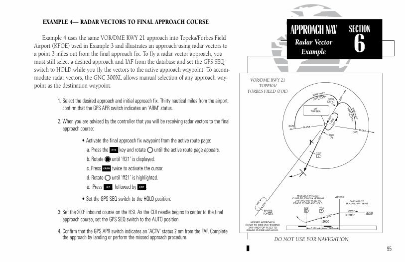
EXAMPLE 4— RADAR VECTORS TO FINAL APPROACH COURSE
Example 4 uses the same VOR/DME RWY 21 approach into Topeka/Forbes FieldAirport (KFOE) used in Example 3 and illustrates an approach using radar vectors toa point 3 miles out from the final approach fix. To fly a radar vector approach, youmust still select a desired approach and IAF from the database and set the GPS SEQswitch to HOLD while you fly the vectors to the active approach waypoint. To accom-modate radar vectors, the GNC 300XL allows manual selection of any approach way-point as the destination waypoint.
1. Select the desired approach and initial approach fix. Thirty nautical miles from the airport,confirm that the GPS APR switch indicates an ‘ARM’ status.
2. When you are advised by the controller that you will be receiving radar vectors to the finalapproach course:
• Activate the final approach fix waypoint from the active route page:
a. Press the R key and rotate O until the active route page appears.
b. Rotate K until ‘ff21’ is displayed.
c. Press C twice to activate the cursor.
d. Rotate O until ‘ff21’ is highlighted.
e. Press D, followed by E.
• Set the GPS SEQ switch to the HOLD position.
3. Set the 200º inbound course on the HSI. As the CDI needle begins to center to the finalapproach course, set the GPS SEQ switch to the AUTO position.
4. Confirm that the GPS APR switch indicates an ‘ACTV’ status 2 nm from the FAF. Completethe approach by landing or perform the missed approach procedure.
95
SECTION
6APPROACH NAV
Radar VectorExample
DO NOT USE FOR NAVIGATION
MISSED APPROACHCLIMB TO 3000 VIA HEADING
240° AND TOP R-213 TOERASE 25 DME AND HOLD.
25TOP
7TOP
7
7
TOP
TOP
VORTAC
ONE MINUTEHOLDING PATTERN
048°
228°
205°
205°
1 M
IN
200°
205°
IAFTOPEKA
R-258(IAF)
2600(7)
(IAF)R-094
3000205° (7)
Arc
Arc
3000
3000
NoPT
NoP
T
ERASE
VOR/DME RWY 21TOPEKA/
FORBES FIELD (FOE)
5 NM 7 NM
MISSED APPROACHCLIMB TO 3000 VIA HEADING
240° AND TOP R-213 TOERASE 25 DME AND HOLD.
3000
2600
200°12 7
TOP TOP
VORTAC
ONE MINUTEHOLDING PATTERN
025°205°
300xl manual 1/25/99 2:36 PM Page 95
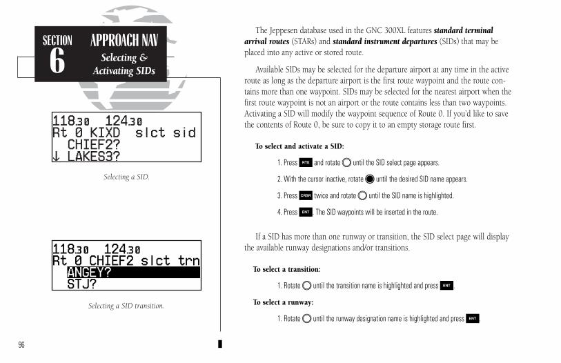
The Jeppesen database used in the GNC 300XL features standard terminalarrival routes (STARs) and standard instrument departures (SIDs) that may beplaced into any active or stored route.
Available SIDs may be selected for the departure airport at any time in the activeroute as long as the departure airport is the first route waypoint and the route con-tains more than one waypoint. SIDs may be selected for the nearest airport when thefirst route waypoint is not an airport or the route contains less than two waypoints.Activating a SID will modify the waypoint sequence of Route 0. If you’d like to savethe contents of Route 0, be sure to copy it to an empty storage route first.
To select and activate a SID:
1. Press R and rotate O until the SID select page appears.
2. With the cursor inactive, rotate K until the desired SID name appears.
3. Press C twice and rotate O until the SID name is highlighted.
4. Press E. The SID waypoints will be inserted in the route.
If a SID has more than one runway or transition, the SID select page will displaythe available runway designations and/or transitions.
To select a transition:
1. Rotate O until the transition name is highlighted and press E.
To select a runway:
1. Rotate O until the runway designation name is highlighted and press E.
96
Selecting a SID transition.
Selecting a SID.
SECTION
6APPROACH NAV
Selecting &Activating SIDs
300xl manual 1/25/99 2:36 PM Page 96

The SID select page also allows you to review all the available SIDs for the depar-ture airport and select, delete or change the active SID.
To replace/delete the active SID:
1. Press R and rotate O until the SID select page appears.
2. Press C twice. The active SID (denoted by an asterisk) is highlighted.
3. To replace the active SID with another available SID, rotate O to highlight the desiredSID. Complete the selection by pressing E.
4. To delete the active SID, press \, followed by E. The SID waypoints will beremoved from the active route.
SIDs can also be selected and deleted from storage routes through the RouteCatalog page.
To select a SID from the route catalog page:
1. Display the desired route on the route catalog page.
2. Select ‘sid?’ in the route operations field and press E.
3. Select the desired SID and transitions.
4. The SID waypoints will be inserted into the route and the route review page will be displayed.
To delete a SID from the route catalog page:
1. Display the desired route on the route catalog page.
2. Select ‘sid?’ in the route operations field and press E.
3. Rotate O to highlight the selected SID (denoted by an asterisk). Press \, then E. 97
SIDs may be saved with any stored route.
The SID select page allows you to select a newSID on the fly.
SECTION
6APPROACH NAV
Selecting &Deleting SIDs
300xl manual 1/25/99 2:36 PM Page 97
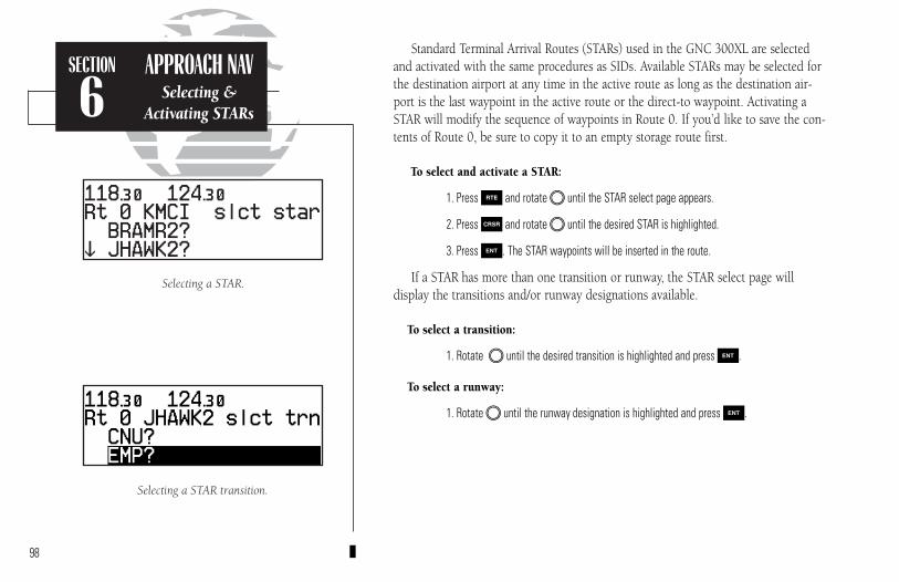
Standard Terminal Arrival Routes (STARs) used in the GNC 300XL are selectedand activated with the same procedures as SIDs. Available STARs may be selected forthe destination airport at any time in the active route as long as the destination air-port is the last waypoint in the active route or the direct-to waypoint. Activating aSTAR will modify the sequence of waypoints in Route 0. If you’d like to save the con-tents of Route 0, be sure to copy it to an empty storage route first.
To select and activate a STAR:
1. Press R and rotate O until the STAR select page appears.
2. Press C and rotate O until the desired STAR is highlighted.
3. Press E. The STAR waypoints will be inserted in the route.
If a STAR has more than one transition or runway, the STAR select page will display the transitions and/or runway designations available.
To select a transition:
1. Rotate O until the desired transition is highlighted and press E.
To select a runway:
1. Rotate O until the runway designation is highlighted and press E.
98
Selecting a STAR transition.
Selecting a STAR.
SECTION
6APPROACH NAV
Selecting &Activating STARs
300xl manual 1/25/99 2:36 PM Page 98

The STAR select page also allows you to review all available STARs for the destina-tion airport and select, delete or change the active STAR.
To replace/delete a STAR:
1. Press R and rotate O until the STAR select page appears.
2. Press C twice. The active STAR (denoted by an asterisk) is highlighted.
3. To replace the active STAR with another available STAR, rotate O to highlight thedesired STAR. Complete the selection by pressing E.
4. To delete the active STAR, press \, followed by E. The STAR waypoints will beremoved from the active route.
STARs can also be selected and deleted from storage routes through the route catalog page.
To select a STAR from the route catalog page:
1. Display the desired route on the route catalog page.
2. Select ‘star?’ in the route operations field and press E.
3. Select the desired STAR and transitions.
4. The STAR waypoints will be inserted into the route and the route review page will be displayed.
To delete a STAR from the route catalog page:
1. Display the desired route on the route catalog page.
2. Select ‘star?’ in the route operations field and press E.
3. Rotate O to highlight the selected STAR (denoted by an asterisk). Press \ followedby E. The STAR waypoints will be deleted from the route. 99
STARs may be saved in any storage route.
Deleting the active STAR.
SECTION
6APPROACH NAV
Selecting &Deleting STARs
300xl manual 1/25/99 2:36 PM Page 99
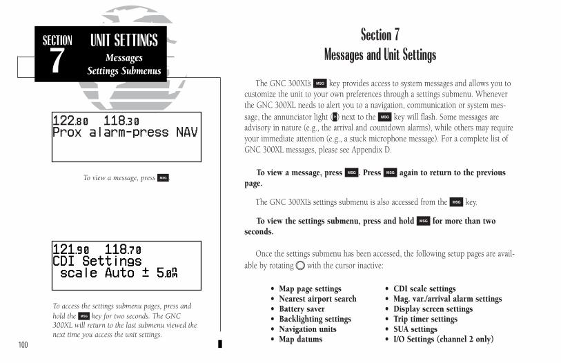
100
SECTION
7UNIT SETTINGS
MessagesSettings Submenus
To access the settings submenu pages, press andhold the M key for two seconds. The GNC300XL will return to the last submenu viewed thenext time you access the unit settings.
To view a message, press M.
Section 7Messages and Unit Settings
The GNC 300XL’s M key provides access to system messages and allows you to customize the unit to your own preferences through a settings submenu. Wheneverthe GNC 300XL needs to alert you to a navigation, communication or system mes-sage, the annunciator light (U) next to the M key will flash. Some messages areadvisory in nature (e.g., the arrival and countdown alarms), while others may requireyour immediate attention (e.g., a stuck microphone message). For a complete list ofGNC 300XL messages, please see Appendix D.
To view a message, press M. Press M again to return to the previouspage.
The GNC 300XL’s settings submenu is also accessed from the M key.
To view the settings submenu, press and hold M for more than two seconds.
Once the settings submenu has been accessed, the following setup pages are avail-able by rotating O with the cursor inactive:
• Map page settings • CDI scale settings• Nearest airport search • Mag. var./arrival alarm settings• Battery saver • Display screen settings• Backlighting settings • Trip timer settings• Navigation units • SUA settings• Map datums • I/O Settings (channel 2 only)
300xl manual 1/25/99 2:36 PM Page 100

101
SECTION
7UNIT SETTINGS
Map PageSetup
The GNC 300XL’s map page is designed to be a flexible tool that can be custom-tailored to your navigation needs. The map setup page provides access to many ofthe features and functions that will help you configure the map page to your ownpreferences. From the map setup page you can set the map orientation, automaticzoom, and specify which waypoints and airspace boundaries you wish to display.
The map orientation setting allows you to orient the top of the map display toyour current ground track (‘trk up’), fix the top of the map to north like a paper chart(‘nrth up’) or set the top of the map along your desired track (‘dtk up’).
To change the map orientation:
1. Press and hold M, then rotate O to select the ‘MAP Setup’ page.
2. Press C twice to highlight the orientation field.
3. Rotate K to select ‘trk up’, ‘dtk up’ or ‘nrth up’.
The automatic zoom feature will automatically adjust the map display scale dur-ing your flight. Starting at an en route scale of 300 (nautical miles, statute miles orkilometers) the scale will adjust through each lower scale, stopping at a scale of 1 asyou approach your destination waypoint.
To turn the automatic zoom feature on or off:
1. Press and hold M, then rotate O to select the ‘MAP Setup’ page.
2. Press C twice and rotate O to highlight the ‘auto zoom’ field.
3. Rotate K to select ‘on’ or ‘off’.The map orientation may be set to north up, trackup or desired track up. This determines whatdirection the top of the map display is oriented to.
Map setup page
300xl manual 1/25/99 2:36 PM Page 101

102
SECTION
7UNIT SETTINGS
Map PageSetup
The map setup page also allows you to control whether or not the various way-point types and the identifiers for these waypoints are displayed. Settings for eachwaypoint type allow you to select the maximum scale at which that feature should bedisplayed, or you may turn that waypoint type off for all scales. For example, by set-ting ‘VOR’ at 80, VOR waypoints will appear on the map display at all scales from 80on down, but not at 120, 200 or 300.
To display airports, navaids and/or user waypoints:
1. Press and hold M, then rotate O to display the ‘MAP Setup’ page.
2. Press C twice and rotate O to highlight ‘apt’, ‘vor’, ‘ndb’, ‘int’ or ‘user’.
3. Rotate K to select the maximum map scale for that waypoint type, or select ‘off’ to dis-able the waypoint type entirely.
To display waypoint identifiers:
1. Press and hold M, then rotate O to display the ‘MAP Setup’ page.
2. Press C twice and rotate O to highlight ‘apt ident’, ‘vor ident’, ‘ndb ident’, ‘int ident’,or ‘user ident’.
3. Rotate K to select the maximum map scale for that waypoint category, or select ‘off’ todisable the waypoint identifiers.
The boundaries for airspaces that appear on the map display may be enabled ordisabled by airspace type. As described above for waypoints, you select the maximumscale at which the airspace should appear or turn the airspace type off entirely.Airspace categories for Class B/CTA, Class C/TMA, MOA, restricted and other SUAs areprovided. ‘Other sua’ includes alert, caution, danger, training and warning areas.
A scale setting of ‘200’ for airports will displayairport locations on the map display for all scalesfrom ‘200’ on down. Airports will not appear onthe map display at a scale setting of ‘300’.
The automatic zoom feature will automaticallyadjust the map display through progressivelylower scale settings as you approach your destination waypoint.
300xl manual 1/25/99 2:36 PM Page 102
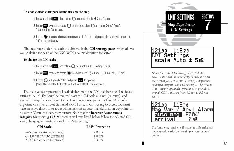
103
SECTION
7UNIT SETTINGSMap Page Setup
CDI Settings
To enable/disable airspace boundaries on the map:
1. Press and hold M, then rotate O to select the ‘MAP Setup’ page.
2. Press C twice and rotate O to highlight ‘class B/cta’, ‘class C/tma’, ‘moa’, ‘restricted’ or ‘other sua’.
3. Rotate K to select the maximum map scale for the designated airspace type, or select‘off’ to never display.
The next page under the settings submenu is the CDI settings page, which allowsyou to define the scale of the GNC 300XL’s course deviation indicator.
To change the CDI scale:
1. Press and hold M, and rotate O to select the ‘CDI Settings’ page.
2. Press C twice and rotate K to select ‘Auto’, ‘+- 5.0 nm’, ‘+- 1.0 nm’ or ‘+- 0.3 nm’.
3. Rotate O to highlight ‘ok?’ and press E to approve. (Note: the selected CDI scale will not take effect until approved.)
The scale values represent full scale deflection of the CDI to either side. The defaultsetting is ‘Auto’. The ‘Auto’ setting will start the CDI scale at 5 nm (en route), andgradually ramp the scale down to the 1 nm range once you are within 30 nm of adeparture or arrival airport (terminal area). For auto CDI scaling to occur, you musthave an active direct-to or route with an airport as your final destination waypoint, orbe within 30 nm of a departure airport. Note that the Receiver AutonomousIntegrity Monitoring (RAIM) protection limits listed below follow the selected CDIscale, changing automatically with the ‘Auto’ setting:
CDI Scale RAIM Protection
+/-5.0 nm or Auto (en route) 2.0 nm+/- 1.0 nm or Auto (terminal) 1.0 nm+/- 0.3 nm or Auto (approach) 0.3 nm
When the ‘auto’ CDI setting is selected, the GNC 300XL will automatically change the CDI scale when you are within 30 nm of a departureor arrival airport. The CDI setting will be reset to‘Auto’ during approach operations, to provide asmooth CDI transition from 5.0 nm to 0.3 nmscales.
The ‘auto mag’ setting will automatically calculatethe magnetic variation based upon your currentposition.
300xl manual 1/25/99 2:36 PM Page 103

104
SECTION
7UNIT SETTINGS
Magnetic VariationArrival Alarm
The GNC 300XL has three magnetic variation options: true, auto, or user-defined.
To set the magnetic variation:
1. Press and hold M, and use O to display the ‘Mag Var/Arvl Alarm’ page.
2. Press C twice and use K to select ‘auto mag’, ‘true hdg’ or ‘user mag’.
3. If user is selected, use O to highlight the magnetic variation value, and use K and Oto enter the value and ‘E’ or ‘W’. Press C to finish.
If ‘auto’ mag var is selected, all track, course and heading information will be cor-rected to the magnetic variation computed by the GPS receiver. The ‘true’ setting willreference all information to true north, and the ‘user’ setting will correct information toan entered value.
The GNC 300XL’s arrival alarm can be set to notify the pilot with a message whenyou have reached a user defined distance to a final destination waypoint (the direct-towaypoint or the last waypoint in a route). Once you have reached the set distance (upto 99.9 units), an ‘Arrival at _____’ message will be displayed.
To set the arrival alarm distance:
1. Press and hold M, and use O to display the ‘Mag Var/Arvl Alarm’ page.
2. Press C twice and use O to select the arrival distance field.
3. Use K and O to enter the desired distance. Press C to finish.
The nearest airport search settings allow you to define the runway length and surface type used in determining the nine nearest airports displayed. A minimum run-way length and surface type may be entered to prevent airports with small runways, orrunways that are not of appropriate surface, from being displayed. The default settingsare ‘0 ft/mt’ for runway length and ‘any’ for runway surface type.
The runway length and surface type settings allowpilots of large, high-performance aircraft to directthe T key function to ignore those airports atwhich if would be difficult, if not impossible, toland their aircraft.
Setting the arrival alarm to 10 nautical miles.
300xl manual 1/25/99 2:36 PM Page 104

105
SECTION
7UNIT SETTINGSNearest Airports
Battery Saver
To set the minimum runway length and runway surface:
1. Press and hold M and use O to display the ‘Nearest apt search’ page.
2. Press C twice and use K and O to enter the minimum runway length upon whichyour aircraft can land (up to 9999 units). Press E to accept the distance.
3. Rotate K to display the surface selection you desire. Choices include:
• any surface • hard only surface• soft/hard surface • water only surface
4. Use O to select ‘ok?’ and press E to confirm.
The GNC 300XL’s battery saver feature can be programmed to automaticallyturn off the backlighting when using the optional remote battery pack. This willincrease the remote battery life in the event of power failure. During this time, theGNC 300XL will continue to navigate and track satellites, but will not backlight thedisplay until a key is pressed or a knob is turned.
To set the display timeout:
1. Press and hold M and rotate O to display the ‘Battery saver’ page.
2. Press C twice to activate the cursor.
3. Rotate K until the desired value is displayed (0, 30, 60 or 90 seconds). Entering 0 willleave the display on at all times. Press C to finish.
The GNC 300XL features automatic contrast and backlighting control to adjust thedisplay for optimum viewing in any condition. This is done using a photocell at thetop left corner of the display bezel. It is important that this photocell not be coveredto ensure proper display adjustment. You may also select manual control of the dis-play contrast and backlighting to tailor the GNC 300XL to your needs.
Display timeout settings. As shown, the displaybacklight will turn off after 30 seconds to conservepower in the optional battery pack.
300xl manual 1/25/99 2:36 PM Page 105

106
SECTION
7UNIT SETTINGSDisplay Settings
To change the display contrast settings:
1. Press and hold M and rotate O to show the ‘Display’ settings page.
2. Press C twice and use K to select ‘auto’ or ‘manual’ control.
3. Press E.
4. If ‘manual’ is selected, use K to set the display contrast level. (If ‘auto’ is selected you may also change the offset level to your preference.)
5. Press C to complete.
The ‘mode’ selection allows you to display on-screen characters as black on a lightgreen background (positive) or light green on a black background (negative). With the‘auto’ setting the photocell selects the best mode for day or night viewing.
To change the display mode settings:
1. Press and hold M, and rotate O to show the ‘Display’ settings page.
2. Press C twice and use O to highlight the ‘mode’ field.
3. Rotate K to select ‘pstv’, ‘ngtv’ or ‘auto’.
4. If ‘auto’ is selected, rotate O to highlight the threshold level, and use K to select the level at which the display will switch from positive to negative for night time use. (Note: Some experimentation may be necessary to obtain the desired response level.)
Setting the display mode to ‘negative’ will displayon-screen characters as light green on a blackbackground. This setting is suitable for nightoperation.
The display contrast may be set to automaticallyadjust to varying lighting conditions, using thebuilt-in photocell.
300xl manual 1/25/99 2:36 PM Page 106
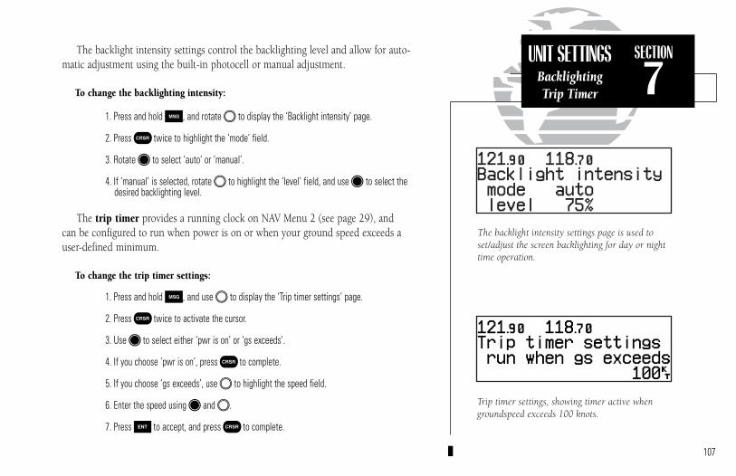
107
SECTION
7UNIT SETTINGS
BacklightingTrip Timer
The backlight intensity settings control the backlighting level and allow for auto-matic adjustment using the built-in photocell or manual adjustment.
To change the backlighting intensity:
1. Press and hold M, and rotate O to display the ‘Backlight intensity’ page.
2. Press C twice to highlight the ‘mode’ field.
3. Rotate K to select ‘auto’ or ‘manual’.
4. If ‘manual’ is selected, rotate O to highlight the ‘level’ field, and use K to select the desired backlighting level.
The trip timer provides a running clock on NAV Menu 2 (see page 29), and can be configured to run when power is on or when your ground speed exceeds auser-defined minimum.
To change the trip timer settings:
1. Press and hold M, and use O to display the ‘Trip timer settings’ page.
2. Press C twice to activate the cursor.
3. Use K to select either ‘pwr is on’ or ‘gs exceeds’.
4. If you choose ‘pwr is on’, press C to complete.
5. If you choose ‘gs exceeds’, use O to highlight the speed field.
6. Enter the speed using K and O.
7. Press E to accept, and press C to complete.
Trip timer settings, showing timer active whengroundspeed exceeds 100 knots.
The backlight intensity settings page is used toset/adjust the screen backlighting for day or nighttime operation.
300xl manual 1/25/99 2:36 PM Page 107
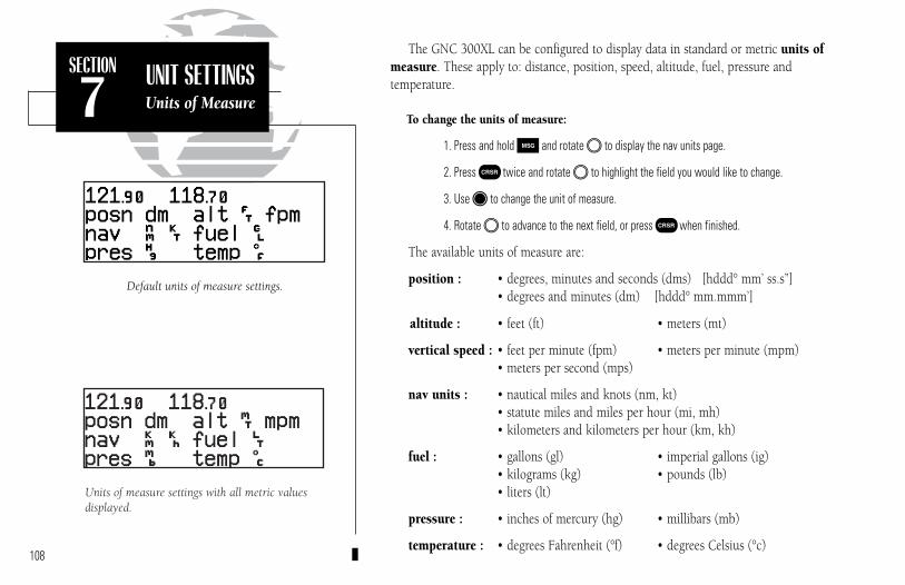
108
SECTION
7UNIT SETTINGSUnits of Measure
The GNC 300XL can be configured to display data in standard or metric units ofmeasure. These apply to: distance, position, speed, altitude, fuel, pressure and temperature.
To change the units of measure:
1. Press and hold M and rotate O to display the nav units page.
2. Press C twice and rotate O to highlight the field you would like to change.
3. Use K to change the unit of measure.
4. Rotate O to advance to the next field, or press C when finished.
The available units of measure are:
position : • degrees, minutes and seconds (dms) [hddd° mm’ ss.s”] • degrees and minutes (dm) [hddd° mm.mmm’]
altitude : • feet (ft) • meters (mt)
vertical speed : • feet per minute (fpm) • meters per minute (mpm)• meters per second (mps)
nav units : • nautical miles and knots (nm, kt)• statute miles and miles per hour (mi, mh)• kilometers and kilometers per hour (km, kh)
fuel : • gallons (gl) • imperial gallons (ig)• kilograms (kg) • pounds (lb)• liters (lt)
pressure : • inches of mercury (hg) • millibars (mb)
temperature : • degrees Fahrenheit (°f) • degrees Celsius (°c)
Default units of measure settings.
Units of measure settings with all metric valuesdisplayed.
300xl manual 1/25/99 2:36 PM Page 108
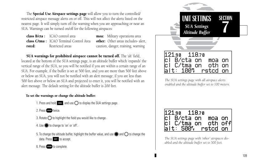
109
SECTION
7UNIT SETTINGS
SUA SettingsAltitude Buffer
The Special Use Airspace settings page will allow you to turn the controlled/restricted airspace message alerts on or off. This will not affect the alerts listed on thenearest page. It will simply turn off the warning when you are approaching or near anSUA. Warnings can be turned on/off for the following airspaces:
class B/cta : ICAO control area moa: Military operations areaclass C/tma : ICAO Terminal Control Area other: Other areas includes- alert,rstcd: Restricted areas caution, danger, training, warning
SUA warnings for prohibited airspace cannot be turned off. The ‘alt’ field,located at the bottom of the SUA settings page, is an altitude buffer which ‘expands’ thevertical range of the SUA, so you will be notified if you are within a certain range of anSUA. For example, if the buffer is set at 500 feet, and you are more than 500 feet aboveor below an SUA, you will not be notified with an alert message; if you are less than500 feet above or below an SUA and projected to enter it, you will be notified with analert message. The default setting for the altitude buffer is 200 feet.
To set the warnings or change the altitude buffer:
1. Press and hold M, and use O to display the SUA settings page.
2. Press C twice.
3. Rotate O to highlight the field you would like to change.
4. Use K to change to ‘on’ or ‘off’.
5. To change the altitude buffer, highlight the buffer value, and use K and O to change thedata. Press E to accept.
6. Press C to complete.
The SUA settings page with ‘other’ airspaces dis-abled and the altitude buffer set to 500 feet.
The SUA settings page with all airspace alertsenabled and the altitude buffer set to 100 meters.
300xl manual 1/25/99 2:36 PM Page 109
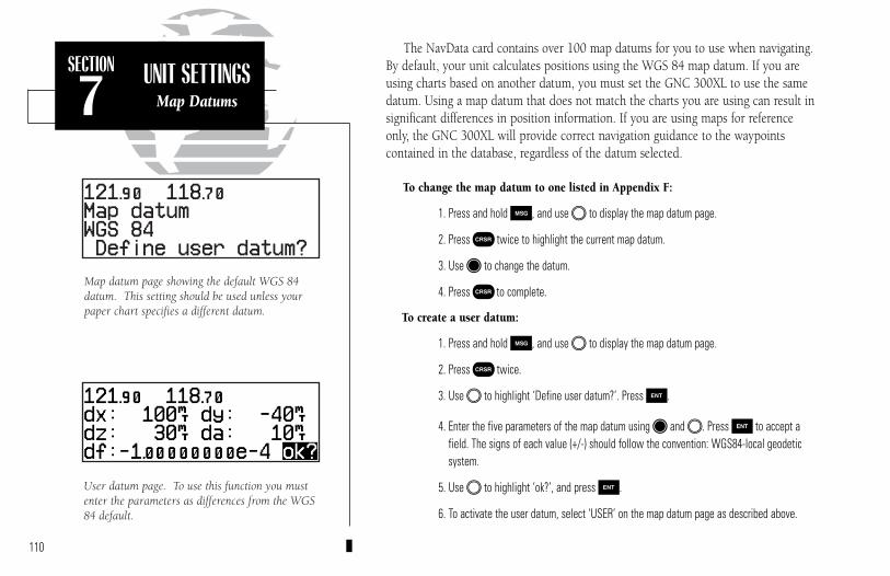
110
SECTION
7UNIT SETTINGS
Map Datums
The NavData card contains over 100 map datums for you to use when navigating.By default, your unit calculates positions using the WGS 84 map datum. If you areusing charts based on another datum, you must set the GNC 300XL to use the samedatum. Using a map datum that does not match the charts you are using can result insignificant differences in position information. If you are using maps for referenceonly, the GNC 300XL will provide correct navigation guidance to the waypoints contained in the database, regardless of the datum selected.
To change the map datum to one listed in Appendix F:
1. Press and hold M, and use O to display the map datum page.
2. Press C twice to highlight the current map datum.
3. Use K to change the datum.
4. Press C to complete.
To create a user datum:
1. Press and hold M, and use O to display the map datum page.
2. Press C twice.
3. Use O to highlight ‘Define user datum?’. Press E.
4. Enter the five parameters of the map datum using K and O. Press E to accept afield. The signs of each value (+/-) should follow the convention: WGS84-local geodeticsystem.
5. Use O to highlight ‘ok?’, and press E.
6. To activate the user datum, select ‘USER’ on the map datum page as described above.
User datum page. To use this function you mustenter the parameters as differences from the WGS84 default.
Map datum page showing the default WGS 84datum. This setting should be used unless yourpaper chart specifies a different datum.
300xl manual 1/25/99 2:36 PM Page 110

111
SECTION
7UNIT SETTINGSI/O Settings
The last page available under the GNC 300XL’s setup menu is the I/O setup page.The I/O setup page lets you configure the GNC 300XL to input RTCM SC-104 correc-tion data, output to a RS-232 mapping device or a PC (with the optional GARMIN PCKit or other mapping software) and select the appropriate baud rate. The I/O setuppage only provides access to I/O channel 2 input/output. For information on using I/Ochannel 1, please see your GNC 300XL installation manual.
To change the output settings for I/O channel 2:
1. Press and hold M, and rotate O until the I/O setup page is displayed.
2. Press C twice, and rotate K to select ‘off’ or ‘plotting’ for output to an RS-232 device.
3. Rotate O to advance the cursor to the baud rate field.
4. Use K to select the desired baud rate (300,1200, 2400, 4800 or 9600).
5. Press C to finish.I/O setup page
300xl manual 1/25/99 2:36 PM Page 111
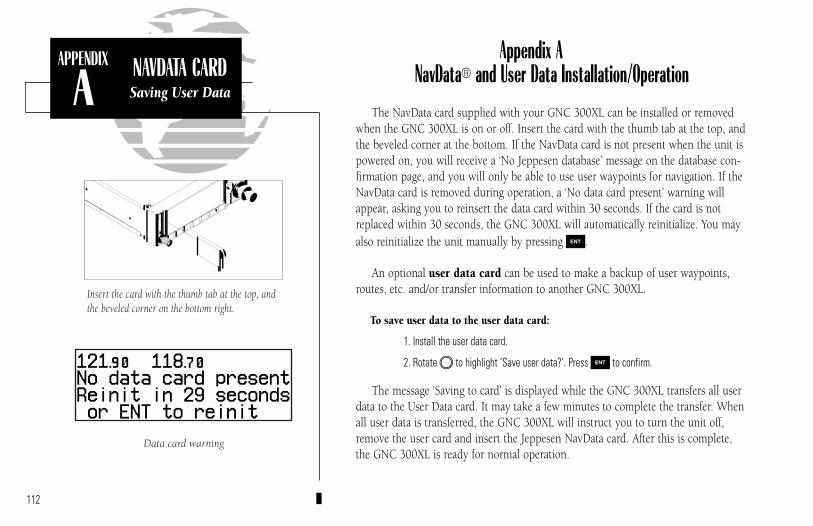
Appendix ANavData® and User Data Installation/Operation
The NavData card supplied with your GNC 300XL can be installed or removedwhen the GNC 300XL is on or off. Insert the card with the thumb tab at the top, andthe beveled corner at the bottom. If the NavData card is not present when the unit ispowered on, you will receive a ‘No Jeppesen database’ message on the database con-firmation page, and you will only be able to use user waypoints for navigation. If theNavData card is removed during operation, a ‘No data card present’ warning willappear, asking you to reinsert the data card within 30 seconds. If the card is notreplaced within 30 seconds, the GNC 300XL will automatically reinitialize. You mayalso reinitialize the unit manually by pressing E.
An optional user data card can be used to make a backup of user waypoints,routes, etc. and/or transfer information to another GNC 300XL.
To save user data to the user data card:
1. Install the user data card.
2. Rotate O to highlight ‘Save user data?’. Press E to confirm.
The message ‘Saving to card’ is displayed while the GNC 300XL transfers all userdata to the User Data card. It may take a few minutes to complete the transfer. Whenall user data is transferred, the GNC 300XL will instruct you to turn the unit off,remove the user card and insert the Jeppesen NavData card. After this is complete,the GNC 300XL is ready for normal operation.
112
APPENDIX
ANAVDATA CARDSaving User Data
Data card warning
Insert the card with the thumb tab at the top, andthe beveled corner on the bottom right.
300xl manual 1/25/99 2:36 PM Page 112

To restore user data from a user data card to the GNC 300XL:
1. Install the user data card.
2. Rotate O to highlight ‘Restore user data?’.
3. Press E.
The GNC 300XL will ask you which type of data to replace. You may choosechecklists, scheduler messages, user waypoints, proximity waypoints, routes, way-point comments, or all data.
4. Rotate K to select the type of data to replace.
You may either replace or update the information in the database. Replacing thedata will replace ALL user data with the data from the card. Updating the data willnot delete unrelated material, but will only change what is necessary to use the datareceived from the user data card.
5. Rotate O to select either ‘Replace?’ or ‘Update?’.
6. Press E to begin transferring data to the GNC 300XL. The GNC 300XL will now transferall of the data requested. This may take a few minutes.
7. To continue with more data transfer types, repeat steps 4, 5 and 6. Otherwise, press Ewhen ‘ok?’ is highlighted.
8. Turn the GNC 300XL off and replace the user data card with a NavData card. The GNC300XL is now ready for normal operation.
113
APPENDIX
ANAVDATA CARDSaving User Data
Data transfer page
Restore data page
300xl manual 1/25/99 2:36 PM Page 113

114
APPENDIX
BINSTALLATION &MAINTENANCE
Appendix BInstallation, Removal and Maintenance of the GNC 300XL
The aviation rack is designed to allow easy removal of the GNC 300XL. This enablesyou to use the unit at home to create routes, interface to a PC, etc. using an optional ACadapter.
To install the GNC 300XL into the aviation rack:
1. Insert a 3/32” allen wrench in the small hole adjacent to the dual knob.
2. Rotate the wrench counterclockwise until it stops to ensure the pawl latch is in the proper position.
3. Insert the GNC 300XL into the aviation rack and rotate the wrench clockwise to secure the unit.To ensure proper connector seating, gently press on the left side of the unit until tightened.
To remove the GNC 300XL from the aviation rack:
1. Insert a 3/32” allen wrench in the small hole adjacent to the dual knob.
2. Rotate the wrench counterclockwise until the GNC 300XL can be removed from the rack.
The GNC 300XL is built to exacting standards anddoes not require user maintenance. If the faceplate andlens require cleaning, use a soft cloth and non-abrasivecleaner.
The user data is maintained by an internal battery witha projected life of 3 to 5 years. If the GNC 300XLdetects a low memory battery, you will be informedwith the message ‘Memory battery low’. Failure tohave the battery replaced may result in loss of dataeach time you turn your unit off. This will greatlyincrease satellite acquisition time and no user data willbe saved. This condition will be accompanied by themessage ‘Stored data lost’.
The GNC 300XL contains a crystal oscillator whichmay drift after many years of operation. If the unitdetects excessive oscillator drift, you will be informedwith the message ‘Osc needs adjustment’. When thisoccurs, contact an authorized GARMIN service centerfor service. Failure to do so may result in severelydegraded acquisition performance.
3/32” ALLENWRENCH
300xl manual 1/25/99 2:36 PM Page 114

115
APPENDIX
CSIMULATOR
Operating mode page
Selecting the simulator mode.
Appendix CThe GNC 300XL’s simulator mode allows you to plan and practice flights in your
home and office using an optional remote battery pack or AC adapter. The simula-tor is not accessible when the GNC 300XL is running off the master avionicsswitch. All waypoint and route planning done in simulator mode will be saved in theunit’s internal memory.
To operate the GNC 300XL in simulator mode:
1. Turn the unit on by rotating the B knob clockwise. The welcome page will appear whilethe unit conducts a self test. Once the self test is complete, the welcome page will bereplaced by the operating mode page.
2. Rotate O to move the cursor over the operating mode field (‘Normal’) .
3. Rotate K to select ‘Simulator’ and press the E key. The cursor will advance to the‘ok?’ prompt. Press E to confirm.
Once the GNC 300XL has been placed in simulator mode, the database confirma-tion page will appear, showing the operating dates, cycle number and database type available.
To acknowledge the database information:
1. Press E.
After the database has been acknowledged, the initial position reference page willappear, where you may specify the starting position for your simulated trip. You candefine the initial position by entering a waypoint identifier in the reference field, orby manually entering coordinates in the lat/lon field.
300xl manual 1/25/99 2:36 PM Page 115
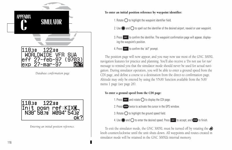
116
APPENDIX
C SIMULATOR
Entering an initial position reference.
Database confirmation page
To enter an initial position reference by waypoint identifier:
1. Rotate O to highlight the waypoint identifier field.
2. Use K and O to spell out the identifier of the desired airport, navaid or user waypoint.
3. Press E to confirm the identifier. The waypoint confirmation page will appear, display-ing the waypoint’s position.
4. Press E to confirm the ‘ok?’ prompt.
The position page will now appear, and you may now use most of the GNC 300XLnavigation features for practice and planning. You’ll also receive a ‘Do not use for nav’message to remind you that the simulator mode should never be used for actual navi-gation. During simulator operation, you will be able to enter a ground speed from theCDI page, and define a course to a destination from the direct-to confirmation page.Altitude may only be entered by using the VNAV function available from the NAVmenu 1 page (see page 26).
To enter a ground speed from the CDI page:
1. Press N and rotate O to display the CDI page.
2. Press C twice to activate the cursor in the GPS window.
3. Rotate O to highlight the ground speed field.
4. Use K and O to enter the desired speed. Press E to accept, and C to finish.
To exit the simulator mode, the GNC 300XL must be turned off by rotating the Bknob counterclockwise until the unit shuts down. All waypoints and routes created insimulator mode will be retained in the GNC 300XL’s internal memory.
300xl manual 1/25/99 2:36 PM Page 116

Altitude input fail - The altitude serializer input is not available forthe GNC 300XL. Check the I/O settings and/orthe serializer installation. If enough satellites areavailable for a 3D position fix, no pilot action isrequired, providing no RAIM warnings are pre-sent. If only a 2D fix is possible, the pilot shouldenter an altitude within 1,000 feet of the currentindicated altitude.
Appr switch stuck - The GPS APR switch is stuck in the ‘pressed’ position.Check the switch/installation.
Approach deleted - The selected approach was deleted from the routebecause not enough room existed to insert a SID orSTAR.
Approach not active - The approach could not transition to the active phasebecause the GPS SEQ switch is set to the HOLD posi-tion, the approach has been manually disarmed usingthe GPS APR switch, the automatic CDI scale is notselected or offset navigation is in effect. Do not descendat the FAF.
Arm approach mode - Approach navigation is available. Press the GPS APRswitch to re-arm the approach.
Arrival at _____ - Your craft has entered the arrival alarm circle for the
indicated waypoint.Arrvl at offst _____ - Your craft has entered the arrival alarm circle for
the indicated waypoint offset by the paralleltrack distance.
Auto CDI slctd - The GNC 300XL has reset the CDI scale preference tothe ‘auto’ setting to permit approach navigation.
Battery low - The optional remote battery pack is low on powerand limited operating time remains. The batteryshould be recharged for continued operation.
Battery rqrs service - A problem has been detected in the optionalremote battery pack. The battery should be ser-viced at an authorized GARMIN service center.
Cannot chng actv wpt - An attempt has been made to modify the position ofthe ‘active to’ or ‘active from’ waypoint. The GNC300XL will not allow the modifications.
Cannot chng wpt sqnc- An attempt has been made to modify an approach, SIDor STAR. The waypoint sequence of approaches, SIDsand STARs may not be modified.
Cannot nav lockd rte - An attempt has been made to activate a routecontaining a locked waypoint. The GNC 300XLcannot perform navigation in this situation.
117
APPENDIX
DMESSAGES &
ABBREVIATIONS
Appendix DGNC 300XL Messages and Abbreviations
The GNC 300XL uses the message page to communicate important information to you. Somemessages are advisory in nature, others are warnings that may require your intervention. This appen-dix provides a complete list of GNC 300XL messages and their meanings.
300xl manual 1/25/99 2:36 PM Page 117
Cannot ofst goto rte - An attempt has been made to engage offset navi-gation feature while the GNC 300XL is navigatingusing a single waypoint route. The GNC 300XLwill not allow offset navigation in this situation.
Checklist is full - The selected checklist is full. No new items canbe added until existing items are deleted.
COM failed - The communications transceiver in the GNC300XL has failed. Take the unit to an authorizedGARMIN service center.
Comment memory full -The waypoint comment memory is full. Youmust delete existing waypoint comments beforeadding new ones.
Configuration reset - The GNC 300XL has detected a failure in itsinstallation configuration memory. Data from theuser memory has been used to reset the configu-ration. Check the installation settings for cor-rectness. If the message persists, the unit is notusable and should be taken to an authorized ser-vice center for repair.
Course input fail - The course input from RS-422 or ARINC 429 isnot available to the GNC 300XL. Check the I/Osettings and/or have the installation checked by
a certified technician. Data card failed - The GNC 300XL has detected a problem with
the data card. The data is not usable and thecard should be returned to Jeppesen or anauthorized GARMIN service center.
Data card write fail - The user data card failed to program. Thecard should be returned to an authorizedGARMIN service center.
Degraded accuracy - The GNC 300XL has detected poor satellitegeometry while RAIM is not available.Additional cross-checking with a secondarynavigation source should be performed to ver-ify the integrity of the GPS position.
Do not use for nav - The GNC 300XL is in the simulator modeand must not be used for actual navigation.
EEPROM write fail - The GNC 300XL has detected a failure whileprogramming its installation configurationmemory. The unit is not usable and should betaken to an authorized service center.
Final altitude alert - The suggested altitude is within 1000 feet ofthe final altitude entered on the VNAV plan-ning page.
Fuel/Air input fail - The fuel and/or air data input is not availableto the GNC 300XL. Check the I/O settingsand the fuel/air system installation.
Heading input fail - The heading input from ARINC 429 is notavailable to the GNC 300XL. Check the I/Osettings and/or have the installation checkedby a certified technician.
Inside SUA - You have entered a Special Use Airspace.
118
APPENDIX
DMESSAGES &
ABBREVIATIONS
300xl manual 1/25/99 2:36 PM Page 118
Invald CPA wpt _____ - The closest point of approach cannot be createdfrom the waypoint entered on the CPA Page.This occurs when the computed point does notfall on one of the route legs, or when a uniquewaypoint name for the closest point of approachcannot be found.
Invalid copy route - A non-empty route was selected for a copyoperation. A route must be empty beforeanother route can be copied to it.
Invalid CPA route - The selected route contains less than two way-points and cannot be used for CPA operations.
Invalid SAR route - The selected route does not contain exactlytwo waypoints and cannot be used for SARoperations.
Leg not smoothed - The upcoming leg is too short for smoothwaypoint transitions. Expect a rapid changein the CDI.
Memory battery low - The battery that sustains user memory is lowand should be replaced by an authorizedGARMIN service center as soon as possible.Failure to do so may result in loss of storeddata, including all user waypoints and routes.
Near SUA < 2 nm - Your position is within 2 nm of an SUA, andyour current course will not take you inside.
Need alt - press NAV - The GNC 300XL needs altitude input inorder to start and/or continue 2D navigation.Press the NAV key and enter your antennaaltitude on the position page. The altitude you enter should be as accurate as possible.An inaccurate altitude will directly translateinto inaccurate position information.
No altitude input - The GNC 300XL has failed to receive altitudedata from the parallel input. Check the I/Osettings and/or the installation. If enoughsatellites are available for a 3D position fix,no pilot action is required, providing noRAIM warnings are present. If only a 2D fixis possible, the pilot should maintain theGPS altitude within 1,000 feet of pressurealtitude, using the position page.
No course input - The GPS SEQ switch is set to the HOLDposition and has no selected course inputfrom the CDI/HSI. Check the state of config-uration switches if installed, or check theCDI/HSI unit.
No DGPS position - Not enough data is available to compute adifferential GPS (DGPS) position.
No RAIM FAF to MAP - RAIM is predicted to NOT be available fromthe final approach fix to the missed approachpoint. The approach is no longer active.
No RTCM input - DGPS data, in an RTCM SC-104 format, isnot available.
119
APPENDIX
DMESSAGES &
ABBREVIATIONS
300xl manual 1/25/99 2:36 PM Page 119

Offset nav cancelled - Offset navigation has been cancelled due to adirect-to operation or modification of theactive route.
Offset nav in effect - Offset navigation mode is in effect.Ofst too big for rte - The parallel track distance is too large for the
active route.Osc needs adjustment - The GNC 300XL has detected excessive drift in its
internal crystal oscillator which may result in longeracquisition time. The unit should be taken to anauthorized GARMIN service center immediately.
Poor GPS coverage - The GNC 300XL cannot acquire sufficientsatellites necessary to provide navigation.
Prox alarm-press NAV - Your craft has penetrated the alarm circle of aproximity waypoint. Press NAV to see the bearingand distance to the proximity waypoint.
Proximity overlap - The circles defined by two proximity way-points overlap. When entering the area of theoverlap, the GNC 300XL will warn you of theclosest proximity waypoint, but not both. Youshould be certain this condition is desirable.
Proximity wpt locked - At least one proximity waypoint is lockedbecause the waypoint has been removed from
the Jeppesen NavData®, the data card is miss-ing, or the data card has failed.
Proximity wpt moved - One or more proximity waypoints weremoved at least 0.33 arc minutes due to a data-base change.
Proximty wpt deleted - One or more proximity waypoints were deletedwhile receiving data from the PC Interface Kit.
Pwr down and re-init - The GNC 300XL is unusable until power hasbeen cycled and the unit re-initialized.Abnormal satellite conditions may exist.
RAIM not available - RAIM is unavailable for the phase of flightyou are currently in (the HSI NAV flag shouldalso appear). Revert to alternate navigation.
RAIM position warn - RAIM has detected position errors exceedingthose allowed for a given phase of flight.Revert to an alternate source of navigation. Ifthe warning occurs during the final approachsegment (FAF to MAP), execute the publishedmissed approach.
RAM failed - The GNC 300XL has detected a failure in itsinternal memory. If the message persists, theGNC 300XL is unusable and should be takento an authorized GARMIN service center.
Rcvr needs service - The GNC 300XL has detected a conditionrequiring service in the receiver hardware.The GNC 300XL should be taken to anauthorized GARMIN service center.
Ready for navigation - The GNC 300XL is ready for navigation.Receiver failed - The GNC 300XL has detected a failure in the
receiver hardware. If the message persists, theGNC 300XL is unusable and should be takento an authorized GARMIN service center.120
APPENDIX
DMESSAGES &
ABBREVIATIONS
300xl manual 1/25/99 2:36 PM Page 120

Remote ENT key stuck - The remote ENT key is stuck in the ‘pressed’state. Check the installation.
Remote XFR key stuck - The remote XFR key is stuck in the ‘pressed’state. Check the installation.
ROM failed - The GNC 300XL has detected a failure in itspermanent memory. If this message occurs, theunit is unusable and should be taken to anauthorized GARMIN service center.
Route is empty - An attempt has been made to activate an emptyroute.
Route is full - An attempt has been made to add more than 31waypoints to a route. The GNC 300XL will notallow more than 31 waypoints per route.
Route truncated - The route was truncated because not enoughroom existed to insert a SID, STAR or approach.
Route wpt deleted - One or more route waypoints were deletedwhile receiving data from the optional PCInterface Kit.
Route wpt locked - At least one route waypoint is locked becausethe waypoint has been removed from theJeppesen NavData®, the data card is missing,or the data card has failed.
Route wpt moved - One or more route waypoints were moved atleast 0.33 arc minutes due to a databasechange.
RTCM input fail - The DGPS data signal was being received buthas now been lost. Check wiring.
Searching the sky - The GNC 300XL is in the search-the-sky mode.Allow the unit to complete data collectionbefore turning it off.
Select auto seq mode - The GPS SEQ switch should be set to the ‘Auto’position to continue navigation.
Set course to ____º - The CDI/HSI should be set to the specifiedcourse.
SID deleted - The SID was deleted from the route because ofinsufficient space in the route.
STAR deleted - The STAR was deleted from the route becauseof insufficient space in the route.
Start altitude chng - The altitude change entered on the VNAVPlanning page is about to begin.
Steep turn ahead - This message appears approximately 90 secondsprior to a turn that requires a bank angle inexcess of 25 degrees in order to stay on course.Turn anticipation will not be provided for theturn.
Stored data lost - Stored user data, including waypoints, routesand satellite orbital data have been lost due to alow memory battery or inadvertent master reset.
Stuck mic/tx disabled - The microphone/headsets have been transmittingcontinuously for 35 seconds, and the transmitterhas been disabled. Releasing the transmit keywill allow you to transmit again. If this messagepersists, check the installation.
121
APPENDIX
DMESSAGES &
ABBREVIATIONS
300xl manual 1/25/99 2:36 PM Page 121

SUA ahead < 10 min - The projected course and current speed willtake you inside an SUA within the next 10minutes.
SUA near & ahead - Your position is within two nautical miles ofan SUA and your current course will take youinside.
Timer expired - The approach timer has expired.User data RX started - Data receive operations have started.Usr data TX complete - Data transmit operations are complete.VNAV cancelled - The VNAV function has been cancelled due to a
change in the active route.WGS 84 datum selectd - The system map datum was changed to WGS
84 because the selected map datum has beenremoved from the NavData card, the datacard is missing, or the data card has failed.
Wpt comment locked - At least one waypoint comment is lockedbecause the waypoint has been removed fromthe Jeppesen NavData®, the data card ismissing, or the data card has failed.
Wpt exists _____ - You have entered a waypoint name on theAutoStore™ Page or user waypoint catalogpage that already exists in memory. Enter a
waypoint name that does not exist.Wpt memory full - The waypoint memory is full. You should
delete unused waypoints to make room fornew waypoints.
122
APPENDIX
DMESSAGES &
ABBREVIATIONS
300xl manual 1/25/99 2:36 PM Page 122

APPENDIX
DMESSAGES &
ABBREVIATIONS
123
This section of Appendix D provides a complete list of GNC 300XL abbreviations andtheir meanings.
ALT- AltitudeAPP- ApproachAPR- ApproachAPT- Airport WaypointARTCC- Air Route Traffic Control CenterARV- ArrivalATF- Aerodrome Traffic FrequencyATS- Automatic Terminal Information
Service (ATIS)AVGS- Aviation GasAZM- Azimuth (bearing)BRG- BearingCAS- Calibrated AirspeedCDI- Course Deviation IndicatorCL B- Class BCL C- Class CCLR- Clearance DeliveryCPA- Closest Point of ApproachCTA- ICAO Control AreaCTAF- Common Traffic Advisory
FrequencyCTF- Common Traffic Advisory
FrequencyCTR- Center (ARTCC)CTS- Course To SteerCUM- CumulativeDALT- Density Altitude
DEG- DegreesDEP- DepartureDIS- Distance To WaypointDME - Distance Measuring EquipmentDOP- Dilution of PrecisionDTK- Desired TrackELEV- ElevationENDUR- EnduranceEPE- Estimated Position ErrorESA- En route Safe AltitudeETA- Estimated Time of ArrivalETE- Estimated Time En routeFIR- Flight Information RegionFLOW- Fuel Flow RateFOB- Fuel On BoardFPM- Feet Per MinuteFR- FromFSS- Flight Service StationFT- FeetFT- Full TimeGL- GallonsGND- GroundGPS- Global Positioning SystemGS- Ground SpeedHDG- HeadingHG- Inches of MercuryIALT- Indicated Altitude
300xl manual 1/25/99 2:36 PM Page 123
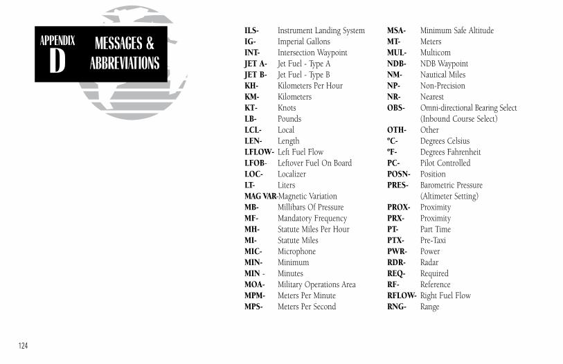
APPENDIX
DMESSAGES &
ABBREVIATIONS
124
ILS- Instrument Landing SystemIG- Imperial GallonsINT- Intersection WaypointJET A- Jet Fuel - Type AJET B- Jet Fuel - Type BKH- Kilometers Per HourKM- KilometersKT- KnotsLB- PoundsLCL- LocalLEN- LengthLFLOW- Left Fuel FlowLFOB- Leftover Fuel On BoardLOC- LocalizerLT- LitersMAG VAR-Magnetic VariationMB- Millibars Of PressureMF- Mandatory FrequencyMH- Statute Miles Per HourMI- Statute MilesMIC- MicrophoneMIN- MinimumMIN - MinutesMOA- Military Operations AreaMPM- Meters Per MinuteMPS- Meters Per Second
MSA- Minimum Safe AltitudeMT- MetersMUL- MulticomNDB- NDB WaypointNM- Nautical MilesNP- Non-PrecisionNR- NearestOBS- Omni-directional Bearing Select
(Inbound Course Select)OTH- OtherºC- Degrees CelsiusºF- Degrees FahrenheitPC- Pilot ControlledPOSN- PositionPRES- Barometric Pressure
(Altimeter Setting)PROX- ProximityPRX- ProximityPT- Part TimePTX- Pre-TaxiPWR- PowerRDR- RadarREQ- RequiredRF- ReferenceRFLOW- Right Fuel FlowRNG- Range
300xl manual 1/25/99 2:36 PM Page 124

APPENDIX
DMESSAGES &
ABBREVIATIONS
125
RNWY- RunwayRSTCD- RestrictedRSV- ReservesRTE- RouteRX- Receive OnlySAR- Search And RescueSEC- SecondsSEQ- SequenceSGL- SignalSID- Standard Instrument
DepartureSLCT- SelectSRFC- SurfaceSTAR- Standard Terminal Arrival
RouteSTR- Steer ToTACAN- TACtical Air Navigational AidTAS- True AirspeedTAT - Total Air TemperatureTEMP- TemperatureTMA- ICAO Terminal Control AreaTRK- Track AngleTRN- Turn AngleTRSA- Terminal Radar Service AreaTWR- TowerTX- Transmit OnlyU- UTC Time
UNI- UnicomURA- User Range AccuracyUSER- User Waypoint
USR- User WaypointUTC- Universal Time Coordinated
(GMT/ Zulu)VN- VNAV or Vertical NavigationVNAV- Vertical NavigationVOR- VOR WaypointWPT- WaypointWX- WeatherXFR- Transfer
300xl manual 1/25/99 2:36 PM Page 125

APPENDIX
E SPECIFICATIONS
126
Whenever the GNC 300XL is connected to theoptional remote battery pack and power from themaster switch is lost, the unit will revert to batterypower. To continue navigation, press any key whenthe power down page appears.
Appendix ESpecifications
PHYSICAL
Size: 6.25”W x 5.8”D x 2”H (159mm x 147mm x 51mm)Weight: 39 ounces (1.11kg)Rack Size: 6.32”W x 5.64”D x 2”H (161mm x 143mm x 51mm)Rack Weight: 11 ounces (0.31kg)
POWER
Input: 10-15V DC with power cable (aircraft power)Optional remote battery pack115V or 230V AC w/ optional adapter
ENVIRONMENTAL
Temperature: -4° F to 158° F (-20°C to 70°C) Operating-67°F to 185°F (-55°C to 85°C) Storage
PERFORMANCE
Comm: 760 channel, aviation band 118-136.975 MHz5-watt minimum transmit power
Receiver: 12 channel PhaseTrac12™Acquisition Time: 45 seconds (typical)
15 seconds (warm start, with ephemeris)Update Rate: 1 per second, continuouslyAccuracy: 15 meters (49ft.) RMS**Dynamics: 999 knots velocity, 3g acceleration
INTERFACES
ARINC 429, Plotting (NMEA 0183 V2.0), Aviation, PC Interface, AltitudeSerializer, Fuel Sensor, Fuel/Air Data Computer
** Subject to accuracy degradation to 100m 2DRMS underthe US DOD-imposed Selective Availability Program.
300xl manual 1/25/99 2:36 PM Page 126

MAP DATUMSAPPENDIX
FAppendix F
Map Datums
127
ADINDAN Ethiopia, Mali, Senegal,Sudan
AFGOOYE SomaliaAIN EL ABD 1970 Bahrain Island, Saudi ArabiaANNA 1 ASTRO 1965 Cocos IslandsARC 1950 Botswana, Lesotho,
Malawi, Swaziland, Zaire,Zambia, Zimbabwe
ARC 1960 Kenya, TanzaniaASCENSION IS 1958 Ascension IslandASTRO B4 SOROL ATOLL Tern IslandASTRO BEACON “E” Iwo Jima IslandASTRO DOS 71/4 St. Helena IslandASTRONOMIC STN 1952 Marcus IslandAUSTRALIAN GEOD 1966 Australia, Tasmania IslandAUSTRALIAN GEOD 1984 Australia, Tasmania IslandAUSTRIA NS AustriaBELGIUM 1950 BelgiumBELLEVUE (IGN) Efate and Erromango
IslandsBERMUDA 1957 Bermuda IslandsBOGOTA OBSERVATORY ColombiaBUKIT RIMPAH IndonesiaCAMP AREA ASTRO AntarcticaCAMPO INCHAUSPE ArgentinaCANTON ASTRO 1966 Phoenix IslandsCAPE South AfricaCAPE CANAVERAL Florida, Bahama IslandsCARTHAGE TunisiaCH-1903 SwitzerlandCHATHAM 1971 Chatham Island (New
Zealand)CHUA ASTRO ParaguayCORREGO ALEGRE BrazilDANISH GI 1934 DenmarkDJAKARTA (BATAVIA) Sumatra Island (Indonesia)
DOS 1968 Gizo Island (New Georgia Islands)
EASTER ISLAND 1967 Easter IslandEUROPEAN 1950 Austria, Belgium, Denmark,
Finland, France, Germany,Gibraltar, Greece, Italy,Luxembourg, Netherlands,Norway, Portugal, Spain,Sweden, Switzerland
EUROPEAN 1979 Austria, Finland,Netherlands, Norway,Spain, Sweden, Switzerland
FINLAND HAYFORD 1910 FinlandG. SEGARA BorneoGANDAJIKA BASE Republic of MaldivesGEODETIC DATUM 1949 New ZealandGGRS 87 GreeceGUAM 1963 Guam IslandGUX 1 ASTRO Guadalcanal IslandHERAT NORTH AfghanistanHJORSEY 1955 IcelandHONG KONG 1963 Hong KongHU-TZU-SHAN TaiwanINDIAN BNGLDSH NEPAL Bangladesh, India, NepalINDIAN MEAN VALUE IndiaINDIAN THAILAND VIETN Thailand, VietnamINDONESIA 74 IndonesiaIRELAND 1965 IrelandISTS 073 ASTRO 1969 Diego GarciaJOHNSTON ISLAND 1961 Johnston IslandKANDAWALA Sri LankaKERGUELEN ISLAND Kerguelen IslandKERTAU 1948 West Malaysia, SingaporeL.C. 5 ASTRO Cayman Brac IslandLIBERIA 1964 LiberiaLUZON MEAN VALUE PhilippinesLUZON MINDANAO IS Mindanao Island
300xl manual 1/25/99 2:36 PM Page 127

APPENDIX
F MAP DATUMS
128
LUZON PHILIPPINES Philippines (excluding Mindanao Isl.)
MAHE 1971 Mahe IslandMARCO ASTRO Salvage IslandsMASSAWA Eritrea (Ethiopia)MERCHICH MoroccoMIDWAY ASTRO 1961 Midway IslandMINNA NigeriaNAD27 ALASKA North American 1927- AlaskaNAD27 BAHAMAS Bahamas (excluding San
Salvador Island)NAD27 CANADA Canada (including
Newfoundland Island)NAD27 CANAL ZONE Canal ZoneNAD27 CARIBBEAN Caribbean (Barbados,
Caicos Islands, Cuba,Dom. Rep., Grd. Cayman,Jamaica, Leeward andTurks Islands)
NAD27 CENTRL AMERICA Central America (Belize,Costa Rica, El Salvador,Guatemala, Honduras,Nicaragua)
NAD27 CONUS Mean Value (CONUS)NAD27 CUBA CubaNAD27 GREENLAND Greenland (Hayes Peninsula)NAD27 MEXICO MexicoNAD27 SAN SALVADR IS San Salvador IslandNAD83 North American 1983-
Alaska, Canada, CentralAmerica, CONUS, Mexico
NAHRWAN MASIRAH IS Masirah Island (Oman)NAHRWAN SAUDI ARABIA Saudi ArabiaNAHRWAN UNITD ARAB E United Arab EmiratesNAPARIMA BWI Trinidad and TobagoNETHERLAND TRIAG ‘21 NetherlandsNOU TRIAG FRANCE FranceNOU TRIAG LUXEMBOURG LuxembourgOBSERVATORIO 1966 Corvo and Flores Islands
(Azores)OLD EGYPTIAN EgyptOLD HAWAIIAN KAUAI KauaiOLD HAWAIIAN MAUI MauiOLD HAWAIIAN MEAN Mean ValueOLD HAWAIIAN OAHU Oahu
OMAN OmanORD SRV GRT BRITAIN England, Isle of Man,
Scotland, Shetland Islands,Wales
PICO DE LAS NIEVES Canary IslandsPITCAIRN ASTRO 1967 Pitcairn IslandPORTUGUESE 1973 PortugalPOTSDAM GermanyPROV SO AMERICAN ‘56 Bolivia, Chile,Colombia,
Ecuador, Guyana, Peru,Venezuela
PROV SO CHILEAN 1963 South ChilePUERTO RICO Puerto Rico & Virgin Isl.QATAR NATIONAL QatarQORNOQ South GreenlandREUNION Mascarene IslandROME 1940 Sardinia IslandRT 90 SwedenSANTO (DOS) Espirito Santo IslandSAO BRAZ Sao Miguel, Santa Maria
Islands (Azores)SAPPER HILL 1943 East Falkland IslandSCHWARZECK NamibiaSOUTH AMERICAN 1969 Argentina, Bolivia, Brazil,
Chile, Colombia, Ecuador,Guyana, Paraguay, Peru, Venezuela, Trinidad/Tobago
SOUTH ASIA SingaporeSOUTHEAST BASE Porto Santo and Madeira
IslandsSOUTHWEST BASE Faial, Graciosa, Pico, Sao
Jorge and Terceira Islands(Azores)
TANANARIVE OBSV 1925 MadagascarTIMBALAI 1948 Brunei and East Malaysia
(Sarawak and Sabah)TOKYO Japan, Korea, OkinawaTRISTAN ASTRO 1968 Tristan da CunhaUSER User datumVITI LEVU 1916 Viti LevuIsland/Fiji IslandsWAKE-ENIWETOK 1960 Marshall IslandsWGS 72 World Geodetic System 1972WGS 84 World Geodetic System 1984YACARE UruguayZANDERIJ Surinam
300xl manual 1/25/99 2:36 PM Page 128

Appendix GTroubleshooting Q & A
The GNC 300XL is a precision navigation instrument that offers a wide array ofperformance navigation features. The ‘Q & A’ section is designed to answer some ofthe common questions regarding the GNC 300XL’s capabilities and operation. If youhave a problem operating your unit, go through the troubleshooting section and referto the reference section noted. If your problem is not listed in the Q & A section, usethe index to find the appropriate reference in the manual. If you still encounter aproblem, please see your authorized dealer or call or fax our customer support staff at913-397-8200 or 913-397-8282 FAX. GARMIN is dedicated to supporting its prod-ucts and customers.
What is RAIM, and how does it affect approach operations?RAIM is an acronym for Receiver Autonomous Integrity Monitoring, a receiver
function that performs a consistency check on all tracked satellites. RAIM ensures thatthe available satellite geometry will allow the receiver to calculate a position within aspecified protection limit (2 nm for oceanic and en route, 1 nm for terminal and 0.3nm for non-precision approaches).
During oceanic, en route and terminal phases of flight, RAIM will be nearly 100%.Because of the tighter protection limit on approaches, there may be times when RAIMis not available. The GNC 300XL automatically monitors RAIM and will warn youwith an alert message (see Appendix D) when it is not available. If RAIM is not avail-able when crossing the FAF, the ACTV annunciator will not illuminate and the pilotmust fly the missed approach procedure. The GNC 300XL’s RAIM prediction function(see page 30) will also allow you to see whether RAIM will be available for a specifieddate and time. NOTE: If RAIM is not predicted to be available for the final approachcourse, the approach will not become active, as indicated by the ACTV annunciator.
129
APPENDIX
GTROUBLE-SHOOTING
Q & A
300xl manual 1/25/99 2:36 PM Page 129

Why aren’t there any approaches available for my route?Approaches are only available when the final route waypoint or direct-to destina-
tion is an airport (some VOR/VORTAC identifiers are similar to airport identifiers). Ifa destination airport does not have a GPS approach, the GNC 300XL will display a‘no procedures in database’ message. For more on selecting an approach, see page 89.
What happens when I select an approach? Can I store a route with anapproach, SID or STAR?
Whenever you load an approach or STAR into the active route, the arrival airportis moved, and a set of approach or arrival waypoints is inserted. If a SID is loadedinto the active route, the SID waypoints will be inserted following the departure air-port in the active route. Note: these modifications only apply to the active route, andwill not affect the corresponding stored route (if you have activated one). Routes canbe stored with an approach, SID or STAR. Keep in mind that the active route iserased when the unit is turned off and overwritten when another route is activated.
When storing routes with an approach, SID or STAR, the GPS will use the way-point information from the current database to define the waypoints. If the databaseis changed or updated, the GNC 300XL will automatically update the information ifthe procedure name has not changed. If an approach, SID or STAR procedure is nolonger available, the route will become locked until the procedure is deleted from theroute or the correct database is installed. For information on loading an approach,SID or STAR, see pages 78-99. See page 69 for instructions on saving and copyingroutes.
Can I file slant Romeo ‘/R’ using my GPS?Yes, you may file your flight plan as /R if your GNC 300XL is a certified A1 or A2
installation. If you are flying en route, you may fly /R with an expired database onlyafter you have verified all route waypoints. Non-precision approaches may not beflown with an expired database. See your approved Airplane Flight ManualSupplement for more information.130
APPENDIX
GTROUBLE-SHOOTING
Q & A
300xl manual 1/25/99 2:36 PM Page 130

What does the GPS APR switch do? What is ‘arming’ an approach?The GPS APR switch must be set to the ARM position for an approach to enter the
active phase. It may be left in the ARM position to simplify approach operation. Itsmain function is to provide the pilot with a quick method of deactivating the approachand returning the CDI scale to the 1 nm scale in the event of a missed approach. Formore on the GPS APR switch and arming approaches, see pages 78-79.
What does the GPS SEQ switch do and when do I use it?The GPS SEQ switch is used to select manual or automatic waypoint sequencing of
waypoints. Setting the GPS SEQ switch to the HOLD position holds your current‘active to’ waypoint as your navigation reference and prevents the GPS from sequenc-ing to the next waypoint. When the GPS SEQ switch is set to the AUTO position,automatic waypoint sequencing is selected, and the GPS will automatically select thenext waypoint in the route once the aircraft has crossed the present active-to waypoint.
AUTO HOLDAutomatic sequencing of waypoints Manual sequencing- ‘HOLDs’ on selected waypoint
Change in HSI does not affect CDI deflection Manually select course to next waypoint from HSIAlways navigates ‘TO’ the active waypoint Will indicate ‘TO’ or ‘FROM’ waypoint
Must be set to AUTO for approach to go active Approach will not go active
The GPS SEQ switch must be set to the HOLD position any time you are deviatingfrom the flight sequence of an approach (e.g., when you are flying radar vectors) orwhen you must cross the same waypoint twice in succession (e.g., a procedure turn orholding pattern). Whenever the GPS SEQ switch is set to the HOLD position, the GNC300XL allows you to select the desired course to/from a waypoint using the HSI, muchlike a VOR, and display a to/from flag for the active-to waypoint. In the AUTO posi-tion, the CDI will always display a ‘TO’ indication for the next waypoint once you’vecrossed the active waypoint. Refer to page 92 for an approach example using a HOLD.
131
APPENDIX
GTROUBLE-SHOOTING
Q & A
300xl manual 1/25/99 2:36 PM Page 131
When should I switch from HOLD to AUTO, and what happens when I do?Once you are ready to resume automatic waypoint sequencing, you must set the
desired course on your HSI two seconds before changing the GPS SEQ switch to theAUTO position. This allows the the desired course to ‘settle’ prior to the GNC 300XLusing it. Once the GPS SEQ switch is set back to the AUTO position, the GNC 300XLwill use the HSI course until you have crossed the active-to waypoint and sequencedto the next route waypoint. See page 80 for more information on the GPS SEQ switch.
Why won’t my unit automatically sequence to the next waypoint?The GNC 300XL will only sequence approach, SID or STAR waypoints when the
GPS SEQ switch is in the AUTO position. For automatic sequencing to occur, youmust also cross the bisector of the turn you are navigating.
How do I skip a waypoint in an approach, SID or STAR?The GNC 300XL allows you to manually select any approach, STAR or SID way-
point as your next ‘active to’ destination. This procedure, called an on-route direct-to,is performed from the active route page by highlighting the desired waypoint andpressing D, then E to approve the selection. The GPS will then provide naviga-tion directly to the selected waypoint, so be sure you have clearance directly to thatposition. See pages 63 & 76 for more information.
How do I fly the GPS with an autopilot and DG heading bug?If you do not have an HSI, you should make your course selections on the OBS
and the DG heading bug.
132
APPENDIX
GTROUBLE-SHOOTING
Q & A
300xl manual 1/25/99 2:36 PM Page 132

When does turn anticipation begin, and what bank angle is expected?The GNC 300XL will smooth adjacent leg transitions based upon a nominal 15º
bank angle (with the ability to roll up to 25º) and provide three pilot cues for turnanticipation: 1) The waypoint annunciator will flash 15 seconds before the turn pointand glow steadily 2 seconds prior to the turn anticipation point. Begin the turn whenthe annunciator goes steady. 2) A flashing ‘next dtk’ prompt will appear on the GNC300XL’s CDI field. Set the HSI to the next dtk value when the waypoint annunciatorstarts flashing. 3) The To/From indicator on the GPS CDI will flip momentarily toindicate that you have crossed the midpoint of the turn. For more information onturn anticipation, see page 77.
When does the CDI scale change, and what does it change to?Whenever an approach is selected and armed, the GNC 300XL will begin a
smooth CDI scale transition from the 5.0 nm to the 0.3 nm scale 30 nm from the des-tination airport (see left). The CDI scale will remain at the 0.3 nm scale from the FAFto the MAP during the active approach. If you are in a missed approach situation, and
would like to return the CDI to the 1 nm scale, youmay deactivate the approach by releasing the GPSAPR switch from the ARM position.
Why does my CDI not respond like a VORwhen the GPS SEQ switch is set to HOLD?
Unlike a VOR, the CDI scale used on GPS equip-ment is based on the cross-track distance to thedesired course, not an angular relationship to thedestination. Therefore, the CDI deflection on theGPS will be consistent regardless of the distance tothe destination, and will not become less sensitivewhen you are further away from the destination. Formore information on the CDI scale, see page 103. 133
APPENDIX
GTROUBLE-SHOOTING
Q & A
5 nm5 nm 5 nm5 nm
2nm
2nm
CDI Scale Transition
0.3 nm
30 nm
2nm
FAF
MAP
1 nm
1 nm
5 nm
1 minute
GPS VOR
300xl manual 1/25/99 2:36 PM Page 133
What is the correct missed approach procedure? How do I select the missedapproach holding point?
To comply with TSO specifications, the GNC 300XL will not automaticallysequence to the missed approach holding point. The first waypoint in the missedapproach procedure will be displayed as the next approach waypoint when the pilotperforms a direct-to AFTER crossing the MAP, which the pilot may activate whenauthorized. All published missed approach procedures must be flown before activat-ing navigation to the holding point. To begin the missed approach procedure prior tothe MAP, the GPS APR switch must be released from the ‘ARM’ position to disarm theapproach and begin transition of the CDI to the 1.0 nm scale.
To activate navigation to the first missed approach waypoint after crossing theMAP, press D, then E. The GNC 300XL will provide direct navigation to theholding point. If you do not have direct clearance to the holding point, set the GPSSEQ switch to the HOLD position until you have intercepted the inbound course tothe holding point. See page 87 for more information on missed approaches.
How do I re-select the same approach or activate a new approach after amissed approach?
After flying all missed approach procedures, you may reactivate the sameapproach for another attempt from the active route page. Once you have been givenclearance for another attempt, select the starting waypoint from the active route listby highlighting the waypoint identifier and pressing D, followed by E. The GNC300XL will provide direct navigation to the selected waypoint and rejoin theapproach in sequence from that point on. If you have disarmed the previousapproach, remember to set the GPS APR switch to the ‘ARM’ position.
To activate a new approach, you must select the new procedure from theapproach select page. To view the approach select page, press R and rotate Ountil the approach select page appears. Press C and rotate O to highlight the newapproach you want to fly. To activate the new approach, press E and select the IAF,if necessary. See page 88 for more information on reactivating an approach.134
APPENDIX
GTROUBLE-SHOOTING
Q & A
300xl manual 1/25/99 2:36 PM Page 134
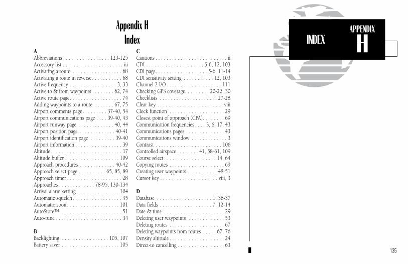
135
APPENDIX
HAppendix H
IndexAAbbreviations . . . . . . . . . . . . . . . . . 123-125Accessory list . . . . . . . . . . . . . . . . . . . . . . iiiActivating a route . . . . . . . . . . . . . . . . . . 68Activating a route in reverse . . . . . . . . . . . 68Active frequency . . . . . . . . . . . . . . . . . 3, 33Active to & from waypoints . . . . . . . . 62, 74Active route page. . . . . . . . . . . . . . . . . . . 74Adding waypoints to a route . . . . . . . 67, 75Airport comments page. . . . . . . . . 37-40, 54Airport communications page . . . . 39-40, 43Airport runway page . . . . . . . . . . . . . 40, 44Airport position page . . . . . . . . . . . . . 40-41Airport identification page . . . . . . . . . 39-40Airport information . . . . . . . . . . . . . . . . . 39Altitude. . . . . . . . . . . . . . . . . . . . . . . . . . 17Altitude buffer . . . . . . . . . . . . . . . . . . . . 109Approach procedures . . . . . . . . . . . . . 40-42Approach select page . . . . . . . . . . 65, 85, 89Approach timer . . . . . . . . . . . . . . . . . . . . 28Approaches . . . . . . . . . . . . . 78-95, 130-134Arrival alarm setting . . . . . . . . . . . . . . . 104Automatic squelch . . . . . . . . . . . . . . . . . . 35Automatic zoom . . . . . . . . . . . . . . . . . . 101AutoStore™ . . . . . . . . . . . . . . . . . . . . . . 51Auto-tune . . . . . . . . . . . . . . . . . . . . . . . . 34
BBacklighting. . . . . . . . . . . . . . . . . . 105, 107Battery saver . . . . . . . . . . . . . . . . . . . . . 105
CCautions . . . . . . . . . . . . . . . . . . . . . . . . . . iiCDI . . . . . . . . . . . . . . . . . . . . . 5-6, 12, 103CDI page. . . . . . . . . . . . . . . . . . . 5-6, 11-14CDI sensitivity setting . . . . . . . . . . . 12, 103Channel 2 I/O . . . . . . . . . . . . . . . . . . . . 111Checking GPS coverage. . . . . . . . . 20-22, 30Checklists . . . . . . . . . . . . . . . . . . . . . 27-28Clear key . . . . . . . . . . . . . . . . . . . . . . . . viiiClock function . . . . . . . . . . . . . . . . . . . . 29Closest point of approach (CPA). . . . . . . . 69Communication frequencies . . . . 3, 6, 17, 43Communications pages . . . . . . . . . . . . . . 43Communications window . . . . . . . . . . . . . 3Contrast . . . . . . . . . . . . . . . . . . . . . . . . 106Controlled airspace . . . . . . . . 41, 58-61, 109Course select . . . . . . . . . . . . . . . . . . . 14, 64Copying routes . . . . . . . . . . . . . . . . . . . . 69Creating user waypoints . . . . . . . . . . . 48-51Cursor key . . . . . . . . . . . . . . . . . . . . . viii, 3
DDatabase . . . . . . . . . . . . . . . . . . . . 1, 36-37Data fields . . . . . . . . . . . . . . . . . . . 7, 12-14Date & time . . . . . . . . . . . . . . . . . . . . . . 29Deleting user waypoints . . . . . . . . . . . . . . 53Deleting routes . . . . . . . . . . . . . . . . . . . . 67Deleting waypoints from routes . . . . . 67, 76Density altitude . . . . . . . . . . . . . . . . . . . . 24Direct-to cancelling . . . . . . . . . . . . . . . . . 63
INDEX
300xl manual 1/25/99 2:36 PM Page 135

136
APPENDIX
H INDEX
Direct-to key . . . . . . . . . . . . . . . . . vii, 5, 63Direct-to navigation . . . . . . . . . . . . 5, 62-64Display contrast. . . . . . . . . . . . . . . . . . . 106Display mode . . . . . . . . . . . . . . . . . . . . 106Displaying airports. . . . . . . . . . . . . . . . . 102Displaying identifiers . . . . . . . . . . . . . . . 102Displaying airspace boundaries. . . . . . . . 103DOP . . . . . . . . . . . . . . . . . . . . . . . . . 20-21Downloading data to another 300XL . . . 112Duplicate waypoints . . . . . . . . . . . . . . . . 55
EEditing routes . . . . . . . . . . . . . . . . . . 67, 75Editing user waypoints. . . . . . . . . . 48-50,53Emergency channel select. . . . . . . . . . . . . 35ENT key. . . . . . . . . . . . . . . . . . . . . . . . . viiiEntering waypoints . . . . . . . . . . . . 38, 48-50EPE . . . . . . . . . . . . . . . . . . . . . . . . . . 20-21Emergency channel select. . . . . . . . . . . . . 36ETE (estimated time en route) . . . . . . . . . 16
FForeword . . . . . . . . . . . . . . . . . . . . . . . . . . iFrequency field . . . . . . . . . . . . . . . . . . . . 33Frequency restrictions . . . . . . . . . . . . 17, 43Fuel planning . . . . . . . . . . . . . . . . . . . 24-25
GGoing to a nearest airport . . . . . . . . . . . . 57GPS APR switch. . . . . . . . . . . . . . . . . . . . 79GPS planning . . . . . . . . . . . . . . . . . . . . . 31GPS SEQ switch . . . . . . . . . . . . . . . . . . . 80Ground speed . . . . . . . . . . . . . . . . . . . 6, 16Ground track (TRK). . . . . . . . . . . . . . . . . 16
H‘Hold’ on a waypoint . . . . . . . . . . . . . 76, 80
IInner knob . . . . . . . . . . . . . . . . . . . . . . . viiiInstallation of the GNC 300XL . . . . . . . . 114Intersections . . . . . . . . . . . . . . . . . . . 37, 47I/O Outputs. . . . . . . . . . . . . . . . . . 111, 126
KKey functions . . . . . . . . . . . . . . . . . . vii, viiiKnob functions . . . . . . . . . . . . . . . . . vii, viii
LLocked waypoints . . . . . . . . . . . . . . . . . . 56
MMagnetic variation . . . . . . . . . . . . . . . . . 104Map datums . . . . . . . . . . . . . . 110, 127-128Map display . . . . . . . . . . . . . . . . . . . 6-7, 15Map orientation . . . . . . . . . . . . . . . . 16, 101Map page . . . . . . . . . . . . . . . 6-8, 11, 15-16Map scales. . . . . . . . . . . . . . . . . . . . . . 8, 16Map setup . . . . . . . . . . . . . . . . . . . 101,103Measurement units . . . . . . . . . . . . . . . . 108Messages . . . . . . . 2, 28, 31, 56, 58, 117-122Missed approaches . . . . . 82, 84, 87-88, 134MSG key. . . . . . . . . . . . . . . . . . . . . viii, 100
NNAV/GPS switch . . . . . . . . . . . . . . . . . . . 79NAV Key . . . . . . . . . . . . . . . . . . . . vii, 4, 11NAV menu 1 . . . . . . . . . . . . . . 4, 11, 23-28
300xl manual 1/25/99 2:36 PM Page 136

137
APPENDIX
HINDEX
NAV menu 2 . . . . . . . . . . . . . . 4, 11, 28-32NAVCOM page . . . . . . . . . . . 4, 8, 11, 17-18NavData cards . . . . . . . . . . . . . 36, 112-113Navigation terms . . . . . . . . . . . . . . . . . . . 13NDBs . . . . . . . . . . . . . . . . . . . . . . . . 37, 46NRST key . . . . . . . . . . . . . . . . . . . vii, 9, 57Nearest airport. . . . . . . . . . . . . . . 9, 57, 104Nearest SUA. . . . . . . . . . . . . . . . . . . . 58-61Nearest waypoints . . . . . . . . . . . . . . . . 9, 57
OOffset navigation . . . . . . . . . . . . . . . . . . . 70Orientation . . . . . . . . . . . . . . . . . . . . . . . 16Outer knob . . . . . . . . . . . . . . . . . . . . . . viii
PPacking list. . . . . . . . . . . . . . . . . . . . . . . . iiiParallel track . . . . . . . . . . . . . . . . . . . 66, 70Position page . . . . . . . . . . . . . . 4, 11, 18-19Power/volume knob. . . . . . . . . . . . . . . . . viiPower on (normal) . . . . . . . . . . . . . . . . . . 1Power off. . . . . . . . . . . . . . . . . . . . . . . . . 10Procedure turns . . . . . . . . . . 80, 83, 86, 131Procedures page . . . . . . . . . . . . . . . . . 40-42Proximity Waypoints . . . . . . . . . . . . . 35, 52
RRAIM prediction . . . . . . . . . . . . . . . . . . . 30RAIM protection . . . . . . . . . . . . . . . . . . 129Radar information . . . . . . . . . . . . . . . . . . 41Receiver status . . . . . . . . . . . . . . . . . . 20-22Reference waypoint . . . . . . . . . . . . . . . . . 19Removal of the GNC 300XL. . . . . . . . . . 114Renaming user waypoints . . . . . . . . . . . . 53
Restoring user data . . . . . . . . . . . . . . . . 113Reversing a route . . . . . . . . . . . . . . . . . . . 68Route catalog page. . . . . . . . . . . . . . . . . . 66Route comments . . . . . . . . . . . . . . . . . . . 66Route key . . . . . . . . . . . . . . . . . . . . . . . . viiRoute navigation . . . . . . . . . . . . . . . . 62, 74Route RAIM Prediction . . . . . . . . . . . . 71-72Routes . . . . . . . . . . . . . . . . . . . . . . . . 62-77Runway page. . . . . . . . . . . . . . . . . . . . . . 44Runway surface . . . . . . . . . . . . . . . . 44, 104
SSatellite acquisition . . . . . . . . . . . . . . . . . . 2Satellite data page . . . . . . . . . . . . . . . . . . 22Satellite information . . . . . . . . . . . . . . 21-22Satellite status page . . . . . . . . . . 2, 11, 20-22Scheduler . . . . . . . . . . . . . . . . . . . . . . . . 31Search-and-rescue operations . . . . . . . . . . 70Settings submenus . . . . . . . . . . . . . . . . . 100SIDs . . . . . . . . . . . . . . . 40-42, 65-66, 96-97Simulator mode . . . . . . . . . . . . . . . . . . . 115 Special Use Airspace (SUA) . . . . . . . . . 58-61Specifications . . . . . . . . . . . . . . . . . . . . 126Standby frequency . . . . . . . . . . . . . 3, 17, 33STARs . . . . . . . . . . . . . 40-42, 65-66, 98-99Storing user data . . . . . . . . . . . . . . . . . . 112SUA alert messages . . . . . . . . . . . . . . . . . 58SUA alert page. . . . . . . . . . . . . . . . . . . . . 59SUA altitude fields . . . . . . . . . . . . . . . . . . 60SUA settings page . . . . . . . . . . . . . . 61, 102Sunrise/sunset planning . . . . . . . . . . . . . 32Squelch . . . . . . . . . . . . . . . . . . . . . . . vii, 35
300xl manual 1/25/99 2:36 PM Page 137
138
APPENDIX
H INDEX
TTable of contents . . . . . . . . . . . . . . . . . . v-viTime . . . . . . . . . . . . . . . . . . . . . . . . . . . 29Transfer key . . . . . . . . . . . . . . . . . viii, 3, 33Trip planning . . . . . . . . . . . . . . . . . . . . . 23Trip timer . . . . . . . . . . . . . . . . . . . . 29, 107Trip timer settings . . . . . . . . . . . . . . . . . 107True air speed . . . . . . . . . . . . . . . . . . . . . 24Turn anticipation . . . . . . . . . . . . . . . . . . . 77
UUnit settings . . . . . . . . . . . . . . . . . . 100-111Units of measure . . . . . . . . . . . . . . . . . . 108User data cards . . . . . . . . . . . . . . . . . . . 112User waypoints . . . . . . . . . . . . 37, 48-51, 53
VVertical navigation (VNAV) . . . . . . . . . 23-26Volume . . . . . . . . . . . . . . . . . . . . . . . vii, 35VORs . . . . . . . . . . . . . . . . . . . . . . . . 37, 45
WWarranty . . . . . . . . . . . . . . . . . . . . . . . . . ivWaypoint categories. . . . . . . . . . . . . . . . . 37Waypoint comment list . . . . . . . . . . . 36, 54Waypoint comments page . . . . . . . . . . . . 54Waypoint confirmation page . . . . . . . . . . 55Waypoint entry . . . . . . . . . . . . . . . . . . . . 38Waypoint holding . . . . . . . . . . . . . . . . . . 76Waypoint identification page . . . . . . . . . . 38Waypoint information. . . . . . . . . . . . . 36-56Waypoint key . . . . . . . . . . . . . . . . . . vii, 36Waypoint list . . . . . . . . . . . . . . . . . . . . . . 53
Waypoint menu . . . . . . . . . . . . . . . . . 36-37Waypoint scanning . . . . . . . . . . . . . . . . . 56Waypoint sequencing . . . . . . . . . . . . . 76-77Waypoints with comments . . . . . . . . . . . . 54Winds aloft . . . . . . . . . . . . . . . . . . . . . . . 26
ZZoom in/out . . . . . . . . . . . . . . . . . . . . 8, 16
300xl manual 1/25/99 2:36 PM Page 138

139
300xl manual 1/25/99 2:36 PM Page 139

© 1999 GARMIN CorporationGARMIN International, Inc., 1200 East 151st Street Olathe, KS 66062
GARMIN (Europe) LTD, Unit 5, The Quadrangle, Abbey Park Industrial Estate, Romsey, SO51 9AQ, UK
GARMIN (Asia) Corp., 4th Fl., No. 1, Lane 45, Pao-Hsing Road, Hsin Tien, Taiwan R.O.C.
Web Site Address: www.garmin.com
Part No. 190-00067-30 Rev. B
300xl manual 1/25/99 2:36 PM Page 140


