68
http://www.mf.unze.ba/Masinstvo Godina (Volume) 14 Broj (Number) 1, Januar- Mart (January - March) 2017.

http://www.mf.unze.ba/Masinstvo
Godina (Volume) 14 Broj (Number) 1, Januar- Mart (January - March) 2017.

1
ISSN 1512-5173 http://www.mf.unze.ba/masinstvo
MAŠINSTVO ČASOPIS ZA MAŠINSKO INŽENJERSTVO
JOURNAL OF MECHANICAL ENGINEERING Godina (Volume) 14, Broj (Number) 1, Zenica, Januar – Mart (January – March) 2017.
Uredništvo (Editorial): Fakultetska 1, 72000 Zenica Bosnia and Herzegovina Tel: +387 32 449 143; 449 145 Fax: +387 32 246 612 e-mail: [email protected] [email protected] [email protected]
Osnivač i izvršni izdavač (Founders and Executive Publisher): University of Zenica Faculty of Mechanical Engineering Fakultetska 1, 72000 Zenica Bosnia and Herzegovina Recenzioni odbor (Review committe): Dr. Safet Isić, Dr. Fuad Hadžikadunić, Dr. Safet Brdarević, Dr. Muhamed Sarvan, Dr. Šefket Goletić, Dr. Nedeljko Vukojević,
Glavni i odgovorni urednik (Editor and Chief): Prof. Dr. Sc. Safet Brdarević
Časopis izlazi tromjesečno (The journal is published quarterly)
Urednički odbor (Editorial Board): Dr. Safet Brdarević (B&H), Dr. Jože Duhovnik (Slovenia), Dr. Vidosav Majstorović (Serbia), Dr. Milan Jurković (Croatia), Dr. Sabahudin Ekinović (B&H), Dr. Gheorge I. Gheorge (Romania), Dr. Alojz Ivanković (Ireland), Dr. Joan Vivancos (Spain), Dr. Ivo Čala (Croatia), Dr. Slavko Arsovski (Serbia), Dr. Albert Weckenman (Germany), Dr. Ibrahim Pašić (France), Dr. Zdravko Krivokapić (Montenegro), Dr. Rainer Lotzien (Germany)
Tehnički urednik (Technical Editor): Prof. Dr. Sabahudin Jašarević Štampa (Print): Štamparija Fojnica d.o.o., Fojnica Uređenje zaključeno (Preparation ended): 31.03.2017.
Časopis je evidentiran u evidenciji javnih glasila pri Ministarstvu nauke, obrazovanja, kulture i sport Federacije Bosne i Hercegovine pod brojem 651. Časopis u pretežnom iznosu finansira osnivač i izdavač. Časopis MAŠINSTVO u pravilu izlazi u četiri broja godišnje. Rukopisi se ne vraćaju
The Journal is listed under No 651 in the list of public journals in the Ministry of science, education, culture and sport of the Federation of Bosnia and Herzegovina. The Journals is mostly financed by founder and publisher. Frequency of Journal MAŠINSTVO is 4 issues a year. Manuscripts are not returned
Časopis objavljuje naučne i stručne radove i informacije od interesa za stručnu i privrednu javnost iz oblasti mašinstva i srodnih grana vezanih za područje primjene i izučavanja mašinstva. Posebno se obrađuju slijedeće tematike: - tehnologija prerade metala, plastike i gume, - projektovanje i konstruisanje mašina i postrojenja, - projektovanje proizvodnih sistema, - energija, - održavanje sredstava za rad, - kvalitet, efikasnost sistema i upravljanje proizvodnim i poslovnim sistemima, - informacije o novim knjigama, - informacije o naučnim skupovima - informacije sa Univerziteta,
The journal publishes scientific and professional papers and information of interest to professional and economic releases in mechanical engineering and related fields. In particular, the following topics are treated: - Technology for processing metal, plastic and rubber, - Design and construction of machines and plants, - The design of production systems, - Energy, - Maintenance funds for the work, - Quality and efficiency of the system and the management of production and business systems, - Information about new books, - Information about scientific meetings - Information from the University,

2
RIJEČ UREDNIKA Poštovane kolegice i kolege U prvom broju četrnaeste godine izlaženja Časopisa „MAŠINSTVO“ predstavljamo Vam 5 radova raznovrsne tematike, koja prevazilazi tradicionalne okvire sadržaja termina mašinstvo. Pored tri rada koji se potpuno uklapaju u shvatanje ovog pojma (Naponska stanja u nosećim konstrukcijama, Proračun parametara specifične mašinske konstrukcije, Analiza konstrukcionih zahtjeva za upravljanje jednim složenim mašinskim sistemom) u ovom broju predstavljamo i dva rada iz stručne oblasti koja je sve više prisutna u realnoj stručnoj stvarnosti, čiji se problemi mogu efikasno rješavati samo u multidisciplinarnom pristupu, u kojem i oblast mašinstva ima svoje mjesto. Takođe Vas informišemo o značajnoj inovaciji studenata Mašinskog fakulteta iz Zenice za koju su dobili međunarodno priznanje. Na prvoj strani korica predstavljamo jednu Laboratoriju Mašinskog fakulteta iz Sarajeva, a na zadnjoj strani korica predstavljamo jednu uspješnu BiH firmu iz oblasti industrije prerade drveta. Nadamo se da ćemo, uz Vašu pomoć, i u ovoj četrnaestoj godini uspješno izvršavati našu misiju.
Vaš glavni i odgovorni urednikProf. emeritus dr. Safet Brdarević
EDITORIAL Dear Colleagues In the first issue, the fourteenth year of publication, the Journal "Engineering" present you 5 papers on different topics, which goes beyond the traditional limits of content available mechanical engineering. In addition, three papers which fully fit into the realization of this idea (The stresses in the support construction, calculation parameters, specific mechanical structures, Analysis of structural requirements for the management of a complex mechanical system) in this issue we present two papers from technical field that is increasingly present in a real professional reality, whose problems can be effectively solved only in a multidisciplinary approach, in which the field of mechanical engineering has its place. Also inform you about significant innovation of students Faculty of Mechanical Engineering in Zenica which have received international recognition. On the first page of the covers, we present a Laboratory Faculty of Mechanical Engineering in Sarajevo, and on the back cover, represents a successful BH company in the field of wood-processing industry. We hope that, with your help, and in this age of fourteen successfully carry out our mission.
Your editor in chiefProf. emeritus dr. Safet Brdarević
SADRŽAJ
1. Naponsko stanje u nosećim valjcima rotacione peći Žiga A., Kačmarčik J. 3
2. Proračun parametara jednošinske viseće željeznice (JVŽ) u prostorijama trase jama pogona „Haljinići“ ZD RMU „Kakanj“ d.o.o. Kakanj Sredojević J, Bajramović K. 11
3. Incineracija u regiji koja pripada Regionalnoj deponiji Mošćanica – Šansa? Selimović S. 23
4. Prednosti korištenja bioreaktora u postupku kontrolisanog kompostiranja biootpada Šišić M., Bikić F. 31
5. Analiza konstrukcionih zahtjeva neophodnih za stabilno upravljanje i kretanje autobusa Ajanović M., Nunić Z., Klisura F., Petković S. 41
Informacije 59 Uputstvo za autore 61
CONTENTS
1. Stress State In Rotary Kiln Support Rollers Žiga A., Kačmarčik J. 3
2. Calculation of Parameters for Overhead Monorail on the Route in Haljinići PIT, ZD RMU "Kakanj" d.o.o. Kakanj Sredojević J, Bajramović K. 11
3. Incineration in Region that Belongs to the Regional Landfill Mošćanica – A Chance? Selimović S. 23
4. Advantages of Bioreactor in the Process of Controlled Composting Bio-Waste Šišić M., Bikić F. 31
5. Analysis of Structural Requirements Necessary for Stable Operation of Buses Ajanović M., Nunić Z., Klisura F., Petković S. 41
Information 59
Instruction for authors 61

Mašinstvo 1(14), 3 – 10, (2017) A. Žiga at al: STRESS STATE IN ROTARY KILN SUPPORT ROLLERS
3
NAPONSKO STANJE U NOSEĆIM VALJCIMA ROTACIONE PEĆI
STRESS STATE IN ROTARY KILN SUPPORT ROLLERS
Alma Žiga Josip Kačmarčik Mašinski fakultet, Univerzitet u Zenici Ključne riječi: noseći valjak, obodni napon Keywords: kiln roller, circumference stress Paper received: 23.10.2016. Paper accepted: 16.01.2017.
Originalni naučni rad REZIME U radu je sprovedena analiza napona koji se javljaju u nosećim valjcima rotacione peći. Naponi u nosećem valjku izazvani su temperaturnim gradijentom, steznim spojem s osovinom i kontaktom s nosećim prstenom. Analiza napona je urađena analitički i numerički, te su dobiveni rezultati uspoređeni.
Original scientific papar
SUMMARY In the paper stress analysis of rotary kiln support rollers is conducted. Stress state in the support rollers is caused by temperature gradient, shrink-fit connection between shaft and roller and by the contact with kiln ring. The stress analysis is done analytically and numerically, and the results obtained are compared.
1. UVOD Noseći prstenovi i valjci su elementi na koje se oslanja rotaciona peć i uslijed toga su izloženi različitim dinamičkim opterećenjima. Opterećenja potiču od same težine peći, zasipa, rotacije peći i temperaturnih gradijenata. Da bi se predvidjelo ponašanje valjaka i procjenio njihov radni vijek neophodno je izračunati ove napone. Postoji ograničen broj studija u literaturi koji ispituju stanje napona u nosećim prstenovima i valjcima. Takvu analizu su proveli Xiao i oslali [1], koji su istraživali raspodjelu kontaknog pritiska i optimizaciju ugla koga valjci formiraju s centrom peći, ali nisu uzeli u obzir uticaj temperature. Dodatno, dosta studija istražuje napone u rotacionoj peći, napone u prstenovima, prenos toplote u peći, itd. [2-7], ali prema znanju autora, ne postoje objavljena studije s detaljnom teoretskom analizom i numeričkom simulacijom napona u nosećim valjcima. Ovaj rad se fokusira na detaljnoj analizi napona u nosećem valjku koji su izazvani kontaktom sa prstenom, termičkim gradijentom i steznim spojem između osovine i valjka. Dodatno, analiza napona u valjku bit će provedena pomoću numeričkih simulacija.
1. INTRODUCTION Riding rings and rollers are supporting elements of rotary kilns and therefore are subjected to various dynamic stresses. These stresses are caused by loads from the kiln weight and row-mix feed, rotation of the kiln and by temperature gradients. In order to predict the rollers behaviour and estimate their service life it is essential to calculate these stresses. There is a limited number of studies in the literature that investigate stress state of the rotary kiln rings and rollers in more details. Such analysis was carried out by Xiao et al. [1], who investigated contact pressure distribution and support angle optimisation of kiln rings and rollers; but they did not include temperature effects. In addition, there are numerous studies investigating the rotary kiln’s stresses, stresses in rings, heat transfer in kilns, etc [2-7], but to authors’ knowledge, there are no published studies with the detailed theoretical investigation and numerical simulations of the stresses in kiln rollers. This paper focuses on detailed analytical analysis of the kiln roller stresses caused by contact with the ring, temperature gradients and shrink-fit between shaft and roller. Additionally, stress analysis in the roller will be conducted by numerical simulations.

Mašinstvo 1(14), 3 – 10, (2017) A. Žiga at al: STRESS STATE IN ROTARY KILN SUPPORT ROLLERS
4
Istraživanje je sprovedeno za slučaj rotacione peći Fabrike cementa u Kaknju, prikazane na slici 1. To je čelična cijev dužine 70 m, unutrašnjeg prečnika 4,4 m, nagiba 3,5° i brzine rotacije 2 obr/min. Masa peći, uključujući oblogu i zasip iznosi oko 1000 t. Oslanja se na tri oslonca koje čine prsten i valjci, raspoređeni duž peći. Osnovne dimenzije i podaci o opterećenju peći, neophodni za dalju analizu, dati su u tabeli 1 i na slici 2.
The investigation is conducted for the case of the rotary kiln in the Cement plant in Kakanj, shown in Fig.1. It is a 70 m long steel tube with inner diameter of 4,4 m, slope of 3.5° and rotation speed of 2 rpm. The mass of the kiln, including refractory line and feed, is around 1000 t. It is supported by three ring-roller stations, spaced along the length of the kiln. The main dimensions and data for the kiln loading, necessary for subsequent analysis, are given in Tab. 1 and in Fig 2.
Slika 1. Rotaciona peć Fabrike cementa u Kaknju Figure 1 Rotary kiln in the cement plant in Kakanj
Slika 2. Opterećenje rotacione peći
Figure 2 Rotary kiln loading
Tabela 1. Dimenzije rotacione peći Table 1 Rotary kiln dimensions
Ring Inner radius,
R1 Outer radius,
R2 Width,
B Roller Width,
Br Inner radius,
Ru Outer radius,
Rv Ring
1 2318 2700 750 980 310 800 Ring
2, 3 2323 2700 880
2. REAKCIJE OSLONACA ROTACIONE PEĆI Kako bi se izračunale reakcije oslonaca, peć je podijeljena na 17 segmenata usljed različite krutosti omotača, položaja oslonaca i pogonskog zupčanika, te kontinuiranih opterećenja, kako je prikazano na slici 3.
2. ROTARY KILN SUPORT REACTIONS In order to calculate support reactions, the kiln is divided into 17 segments, due to different shell rigidity, supports and drive-gear positions, and distributed loads, as shown in Fig.3.

Mašinstvo 1(14), 3 – 10, (2017) A. Žiga at al: STRESS STATE IN ROTARY KILN SUPPORT ROLLERS
5
Peć je modelirana u programu MDSolids-u 3.2 sa sljedećim pretpostavkama: • zasip je ravnomjerno raspoređen duž peći sa
specifičnom težinom od 18,58 kN/m, • zasip je simetrično raspoređen oko vertikalne
ose peći (slika 4), • temperatura ne utiče na krutost omotača. Specifična težina opeke na ulaznoj strani (dužine 18,2 m), tj. na desnoj strani na slici 3. je 44 kN/m. Ostali dio peći ima opeke sa specifičnom težinom od 74 kN/m. Kontinuirano opterećenje na slici 3. odgovara dijagramu iz slike 2. Težina pogonskog zupčanika je FG=353 kN. Težine prstenova su: FR1=353 kN, FR2=406 kN, FR3=410 kN. Kao rezultat analize, dobivene su reakcije u osloncima (čvorovi 4, 9 i 15): F4=2183,7 kN, F9=4013,86 kN and F15=3154 kN. Koristeći najveću vrijednost, na srednjem osloncu, može se dobiti maksimalno opterećenje Q koje djeluje na valjke (slika 4) kao:
9
2cos30FQ =
° (1)
The kiln is modelled in MDSolids3.2 software with following assumptions: • raw-mix is evenly distributed along the kiln
length with specific weight of 18.58 kN/m, • raw-mix is symmetrically distributed around
the vertical axis of kiln (Fig. 4), • temperature does not affect shell rigidity. The specific weight of line bricks on the inlet side (18.2 m length), ie. right-hand side in Fig. 3 is 44 kN/m. The remaining part of the kiln has line bricks with specific weight of 74 kN/m. The distributed loads in Fig.3 correspond to the graph in Fig. 2. The weight of the gear ring is FG= 353 kN. The weights of the rings are: FR1=353 kN, FR2=406 kN, FR3=410 kN. As a result of the analysis, roller support reactions are obtained (nodes 4, 9 and 15): F4=2183.7 kN, F9=4013.86 kN and F15=3154 kN. Using the highest value, in the middle roller station, the maximum load, Q, acting on the rollers (Fig.4) can be obtained as:
9
2cos30FQ =
° (1)
Slika 3. Model peći Figure 3 Kiln model
Slika 4. Reakcije na valjcima
Figure 4 Roller reactions 3. NAPONI U NOSEĆIM VALJCIMA Kod nosećeg valjka, pritisna sila po jedinici dužine iznosi P=2635,88 N/mm i dobiva se iz izraza:
QPB
= (2)
gdje je Q sila opterećenja valjka (1), a B=880 mm je širina prstena.
3. STRESSES IN KILN ROLLERS Pressure force per unit length of support roller has a value P=2635.88 N/mm and it is given by:
QPB
= (2)
where Q is the force acting on the roller (1), and B=880 mm is the ring width.

Mašinstvo 1(14), 3 – 10, (2017) A. Žiga at al: STRESS STATE IN ROTARY KILN SUPPORT ROLLERS
6
Širina kontakte 2a=8,48 mm je proračunata pomoću izraza [8]:
*
4PRaEπ
= , (3)
gdje je R =617,1 mm ekvivalentni radijus, a E* = 15,385 GPa je ekvivalentni modul elastičnosti. Ekvivalentni radijus se računa prema [8]:
1
2
1 1−
⎛ ⎞= +⎜ ⎟⎝ ⎠v
RR R
, (4)
gdje je Rv = 800 mm radijus valjka, a R2 =2700 mm radijus prstena. Ekvivalentni modul elastičnosti je definiran s jednačinom [8]:
2 2
*1 2
1 1 1ν ν− −= +
E E E, (5)
gdje su ν1=ν2=0,3 Poissonovi koeficijenti, a E1=E2=210 GPa moduli elastičnosti materijala valjka i prstena. Oznake 1 i 2 odnose se na valjak i prsten, slijedom. Maksimalna vrijednost pritiska je p0= 396 MPa i locirana je na sredini kontaktne zone, a dobivena je na osnovu izraza [8]:
02Pp
aπ= (6)
Pored pritisnog kontaktnog napona, u valjku se javljaju termički naponi usljed polja temperature i naponi usljed steznog spoja osovina-valjak. Raspodjela termičkog napona u valjku dobivena je na osnovu izraza (7), [9] i prikazana je na slici 5. U proračunu su korištene vrijednosti temperature unutrašnje i vanjske strane valjka: tu=40 ºC, tv =100 ºC, te unutrašnjeg i vanjskog radijusa valjka: Ru=310 mm i Rv=800 mm.
The width of contact 2a=8.48 mm is calculated using [8]:
*
4PRaEπ
= , (3)
where R =617.1 mm is the equivalent radius and E* = 15.385 GPa is the equivalent modulus of elasticity. The equivalent radius is given by [8]:
1
2
1 1−
⎛ ⎞= +⎜ ⎟⎝ ⎠v
RR R
, (4)
where Rv =800 mm is the radius of roller, and R2 =2700 mm is the radius of ring, The equivalent modulus of elasticity is defined with the equation [8]:
2 2
*1 2
1 1 1ν ν− −= +
E E E, (5)
where ν1=ν2=0.3 are Poisson’ ratios, and E1=E2=210 GPa are the modules of elasticity of roller and ring materials. The subscripts 1 and 2 relate to the roller and the ring, respectively. Maximum contact pressure is p0= 396 MPa and it is located in the middle of contact area, and it was calculated using [8]:
02Pp
aπ= (6)
In addition to the contact pressure, there are thermal stresses in roller caused by temperature gradient and stresses caused by shrink-fit between shaft and roller. Thermal stress distribution in roller is obtained using the equation (7), [9] and is shown in Fig. 5. In the calculation values for the inside and outside temperatures of the roller: tu=40 ºC, tv
=100 ºC, and the inside and outside radius of roller: Ru=310 mm and Rv=800 mm, are used.
( )
2 2
2 2 2 2
11
lnln
σ α α αν
⎡ ⎤+⎢ ⎥= ⋅ + ⋅ −
− −⎢ ⎥⎣ ⎦Δ
= +
∫ ∫v
u u
r Rut R R
v u
vv
v
u
r RE t rdr t rdr tr r R R
RTt tR rR
(7)

Mašinstvo 1(14), 3 – 10, (2017) A. Žiga at al: STRESS STATE IN ROTARY KILN SUPPORT ROLLERS
7
Slika 5. Raspodjela termičkog napona kroz
debljinu valjka Figure 5 Thermal stress distribution through
roller thickness Usljed temperature, proizvedene unutar peći, doći će do širenja osovine i valjka. Vrijednosti pomjeranja vanjskog vlakna osovine (0,1936 mm) i unutrašnjeg vlakna valjka (0,381) usljed širenja mogu se dobiti na osnovu izraza za pomjeranje u(r) (8), [9]. Razlika pomjeranja daje zazor između ova dva elementa u vrijednosti od 0,1874 mm.
Slika 6. Raspodjela napona usljed preklopa
kroz debljinu valjka Figure 6 Stress distribution caused by shrink-fit
through roller thickness Due to temperature, produced inside the kiln, elongation of shaft and roller will occur. The values of elongation of the outer radius (0.1936 mm) and the inner radius of roller (0.381) can be obtained by equation for elongation u(r), (8), [9]. The difference between the elongations gives a gap between these two elements which has a value of 0.1874 mm.
1 2
2
2 2 2
1 2 2
1 1 1( ) ( ) ( ) ( )1
1( ) ( )1
1 1( ) (1 2 ) ( )1
u
v
u
v
u
r
R
Ru
v u R
R
v u R
u r t r rdr C r r C rr r
RC r t r rdrR R
C r t r rdrR R
ν αν
ν αν
νν αν
+= ⋅ ⋅ + ⋅ + ⋅
−
+= ⋅ ⋅
− −
+= − ⋅ ⋅
− −
∫
∫
∫
(8)
Prvobitan preklop od 0,26 mm (jednak je maksimalnoj vrijednosti preklopa), usljed djelovanja temperature, smanjit će se i iznositi δp=0,0726 mm. Vrijednosti obodnih napona usljed steznog spoja osovina-valjaka izračunate su na osnovu izraza (9), [9] i date su na slici 6.
( )
( )
2 2
12 2 2
2
12 2 2
2
v uu
v u
vv
v u
R RR pR R
RR pR R
θ
θ
σ
σ
+=
−
=−
(9)
pri čemu je pritisak između osovine i valjka: 2 2
12 22p v u
u v
E R Rp
R Rδ −
= (10)
The original interference of 0.26 mm (equal to maximal interference value), due to temperature, will be lowered and has a new value of δp=0.0726 mm. Circumference stresses due to shrink-fit between shaft and roller are calculated by expression (9), [9] and shown on Fig. 6.
( )
( )
2 2
12 2 2
2
12 2 2
2
v uu
v u
vv
v u
R RR pR R
RR pR R
θ
θ
σ
σ
+=
−
=−
(9)
wherein, the pressure between shaft and roller is: 2 2
12 22p v u
u v
E R Rp
R Rδ −
= (10)
Zbirni obodni napon u vanjskom vlaknu valjka prikazan je na slici 7. Maksimalni pritisni napon u sredini zone kontakta superponira se s

Mašinstvo 1(14), 3 – 10, (2017) A. Žiga at al: STRESS STATE IN ROTARY KILN SUPPORT ROLLERS
8
termičkim naponom i naponom usljed preklopa osovina-valjak i iznosi -463,8 MPa. The total circumferential stress on the outside radius of roller is shown in Figure 7. Maximal
pressure stress, in the middle of contact area, is superimposed with thermal and shrink-fit stresses and it has a value of -463.8 MPa.
Slika 7. Obodni napon u vanjskom vlaknu valjka
Figure 7 Circumference stress on the outside raduis of roller 5. NUMERIČKA ANALIZA Numerička analiza je provedena koristeći program ABAQUS [10]. U svim simulacijama, prsten i valjak modelirani su u ravni, sa samo polovinom domena zbog simetrije, te su primjenjeni uslovi za ravno stanje deformacija. Simulacije su statičke, tj. inercijalni efekti se zanemareni zbog spore rotacije peći. Osobine materijala za oba dijela su osobine čelika. Sistem je izložen djelovanju temperaturnog gradijenta i opterećen kao na slici 4. Osobine analize su: coupled temperature-displacement step, steady-state response. Sistem prsten-valjak je izmrežen, s odgovarajućim osobinama kontakta između dijelova. Za mrežu su korišteni pravougaoni elementi s osam nodova, tipa CPE8T. Ukupan broj elemenata sistema prsten-valjak je 9 444 (slika 8). Mreža je u području kontakta usitnjena kako bi se postigla bolja tačnost rezultata. Osobine kontakta su: penalty friction formulation (koeficijent trenja je 0.1) i surface-to-surface interaction with finite sliding formulation. Nanesene su vrijednosti temperatura unutrašnje i vanjske strane valjka: tu=40 ºC, tv =100 ºC. Da bi nastao preklop od 0,26 mm, osovini je povećan radijus za vrijednost preklopa. U prvom koraku (General, Coupled temp-displacement), istovremeno s djelovanjem temperature, preklop se rješava uklanjanjem čvorova u preklopu.
5. NUMERICAL ANALYSIS Numerical analysis is carried out using ABAQUS software [10]. In all simulations the ring and rollers are modelled in 2D, with only a half of the domain modeled due to symmetry and a plain strain condition is applied. The simulations are static, i.e. inertia effects are neglected due to slow rotation of the kiln. Material properties for both parts are those of steel. Ring-roller system is exposed to temperature gradient and loaded as in figure 4. Analysis features are: coupled temperature-displacement step, steady-state response. Ring-roller system is meshed, with appropriate contact properties between parts. For the mesh, quadrilateral elements with eight nodes, CPE8T type, are used. The total number of elements of the ring-roller system is 9 444 (Fig. 8). The mesh in contact area is refined in order to achive better result accuracy. The contact properties are: penalty friction formulation (coefficient of friction is 0.1) and surface-to-surface interaction with finite sliding formulation. Temperature values on inside and outside radius of roller are applied: tu=40 ºC, tv =100 ºC. In order to get interference of 0.26 mm, the radius of shaft is increased by this value. In the first step (General, Coupled temp-displacement), simultaneously with action of temperature, the interference is resolved by node removal from the interference.
-470-420-370-320-270-220-170-120-70-2030
0 30 60 90 120 150 180O
bodn
i nap
on, M
PaC
ircu
mfe
renc
e st
ress
, MPa
-463,8
ϕ,°
-67,8
Mašinstvo 1(14), 3 – 10, (2017) A. Žiga at al: STRESS STATE IN ROTARY KILN SUPPORT ROLLERS
9
Slika 8. Granični uslovi i opterećenje sistema
prsten-valjak Figure 8 Boundary conditions and the load on
the ring-roller system
Slika 9. Obodni napon u prstenu i valjku –
lijevo, detalj kontakta –desno Figure 9 Circumference stress in the roller and
the ring, detail of contact-right
Slika 10. Obodni napon u vanjskom vlaknu valjka-numerički i analitički
Figure 10 Circumference stress on outside radius of the roller- numerical and analitical
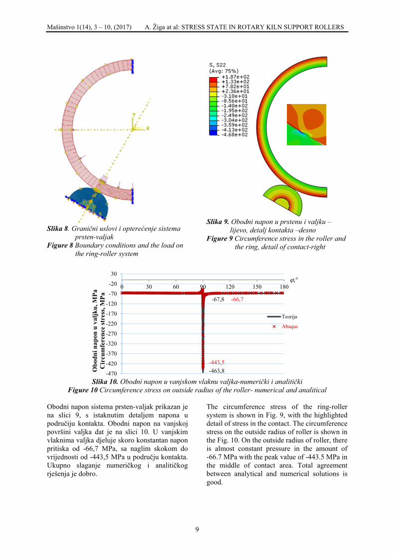
Obodni napon sistema prsten-valjak prikazan je na slici 9, s istaknutim detaljem napona u područiju kontakta. Obodni napon na vanjskoj površini valjka dat je na slici 10. U vanjskim vlaknima valjka djeluje skoro konstantan napon pritiska od -66,7 MPa, sa naglim skokom do vrijednosti od -443,5 MPa u području kontakta. Ukupno slaganje numeričkog i analitičkog rješenja je dobro.
The circumference stress of the ring-roller system is shown in Fig. 9, with the highlighted detail of stress in the contact. The circumference stress on the outside radius of roller is shown in the Fig. 10. On the outside radius of roller, there is almost constant pressure in the amount of -66.7 MPa with the peak value of -443.5 MPa in the middle of contact area. Total agreement between analytical and numerical solutions is good.
-470
-420
-370
-320
-270
-220
-170
-120
-70
-20
30
0 30 60 90 120 150 180
Obo
dni n
apon
u v
aljk
u, M
PaC
ircu
mfe
renc
e st
ress
, MPa
Teorija
Abaqus
ϕ,°
-463,8-443,5
-66,7-67,8

Mašinstvo 1(14), 3 – 10, (2017) A. Žiga at al: STRESS STATE IN ROTARY KILN SUPPORT ROLLERS
10
5. ZAKLJUČAK Noseći valjak preuzima dio opterećenja rotacione peći preko kontakta dvije zakrivljene površine. Kontakt se ostvaruje po pravougaonoj površini vrlo male širine, manje od 1 cm. Dužina površine kontakta, u idealnom slučaju, jednaka je širini prstena, ali može biti smanjena zbog trošenja i formiranja valovitosti površine. Osim ovog kontaknog napona pažnju treba obratiti i na napone koji su izazvani nejednakim zagrijavanjem valjka od strane peći. To stvara značajne, obodne, termičke napone. Zagrijavanje valjka utiče i na njegovo širenje. Dolazi do širenja unutrašnjeg vlakna valjka i vanjskog vlakna osovine. Ova širenja utiču na smanjenje vrijednosti projektovanog preklopa steznog spoja osovina-valjak. Ovo može biti toliko izraženo da valjak sklizne s osovine, što je često zabilježeno u praksi. Analitička i numerička analiza daju mogućnost da se ovi naponi u fazi projektovanja predvide i uzmu u obzir prilikom izbora tolerancije steznog spoja. 6. REFERENCES
5. CONCLUSION The support roller takes one part of the rotary kiln loads over the contact of two curved surfaces. The contact is established on the rectangular area of a very small width, less than 1 cm. A length of contact area is, ideally, equal to a width of the ring, but can be lowered due to wear and formation of surface waviness. In addition to this contact stress, attention should be paid to the stresses caused by unequal roller warming-up by the kiln. This creates significant, circumference, thermal stresses. Warming up the roller also causes its elongation. There is an elongation of the inside radius of roller and the outside radius of shaft. These elongations affects the decrease in value of projected interference of shaft-roller shrink fit. It can be so significant that the roller slides off the shaft, which is often observed in practice. The analytical and numerical analysis provide the option to anticipate and take into account these stresses in a stage of design when tolerance of the shrink-fit is selected.
[1] Xiao Y.; Pan D.; Lei X. Contact pressure distribution and support angle optimization of kiln tyre. //J. Cent. South Univ. Technol. 13, 3, 6(2006), pp 246-250.
[2] A. Žiga, A. Karač, D. Vukojević: Analytical and numerical stress analysis of the rotary kiln ring, Tehnički vjesnik / Technical Gazette 20.6 (2013)
[3] Bowen A. E.; Saxer B. Causes and effect of kiln tyre problems. // IEEE transaction on industry applications. IA-21,2, 3(1985), pp 344-355.
[4] K. Pazand,; M. Shariat Panahi,; M. Pourabdoli, Simulating the mechanical behaviour of a rotary cement kiln using artificial neural networks. //Materials and Design 30 (2009), pp 3468-3473.
[5] J.J. del Coz Diaz,; F. Rodriguez Mazon,; P.J. Garcia Nieto,; F. J. Suarez Dominguez Design and finite element analysis of a wet cycle cement rotary kiln. //Finite Elements in Analysis and Design 39 (2002), pp 17-42.
[6] Chen Z.; Zeng F.; Fan T.; Xiao J.; Shen J. Numerical analysis of static stress on the body of 10000t/d rotary kiln’s main body, International Conference on Experimental Mechanics 2008, edited by Xiaoyuan H., Humin X., Yilan K.
[7] Yoges Sonavane, Eckehard Specht, Numerical analysis of the heat transfer in the wall of rotary kiln using finite element method ANSYS, Seventh International Conference on CFD in the Minerals and Process Industries CISRO, Melbourne, Australia,2009.
[8] Johnson K.L. Contact Mechanics, Cambridge University Press, Cambridge, 1985.
[9] Timoshenko S. Strength of Materials, part II, Advanced Theory and Problems, D. Van Nostrand Company, New York, 1942.
[10] ABAQUS 6.9-1, commercial FEA Software, product of Dassault Systèmes Simulia Corp., Providence, RI, USA. Corresponding author: Alma Žiga Faculty of Mechanical Engineering University of Zenica Fakultetska 1 72 000 Zenica Bosnia and Herzegovina E-mail: [email protected]

Mašinstvo 1(14), 11 – 22, (2017) J. Sredojević et all: CALCULATION OF PARAMETERS…
11
PRORAČUN PARAMETARA JEDNOŠINSKE VISEĆE ŽELJEZNICE (JVŽ) U PROSTORIJAMA TRASE JAMA POGONA „HALJINIĆI“ ZD
RMU „KAKANJ“ D.O.O. KAKANJ
CALCULATION OF PARAMETERS FOR OVERHEAD MONORAIL ON THE ROUTE IN HALJINIĆI PIT, ZD RMU "KAKANJ" D.O.O.
KAKANJ
Jovan Sredojević1 Kasim Bajramović2 1Faculty of Mechanical Engineering, University of Zenica 2ZD RMU „Kakanj“ d.o.o. Kakanj Ključne riječi: Jednošinska viseća željeznica, sila, transport, uskop, niskop Keywords: Overhead monorail, force, transport, inclined shaft (upward and downward) Paper received: 07.10.2016. Paper accepted: 15.12.2016.
Stručni rad REZIME Analizirajući osnovnu problematiku jama pogona „Haljinići“, doprema materijala predstavlja jednu od osnovnih faza rada bitnih za funkcionisanje pogona, te se praćenje i rješavanje problematike vezane za ovaj segment rada, nameće kao ključni u cilju realizacije svih planiranih veličina. Proizvodne aktivnosti, način eksploatacije, vrsta opreme koja se koristi pri tome i niz drugih faktora u značajnoj mjeri zahtijevaju visoku pouzdanost sistema za dopremu repromaterijala kao i transport, odnosno eventualnu dislokaciju iste na druge lokalitete ili van jame. Da bi se postigli navedeni ciljevi, pored pouzdanosti mašina za dopremu, osnovni uslov predstavlja trasa jednošinske viseće željeznice (JVŽ), odnosno prostorije u kojima je ista postavljena, a koje svojim dimenzijama i kvalitetom moraju omogućiti transport opreme veće težine i gabarita.
Professional paper
SUMMARY Haulage of material is one of the basic operational phases of the production process in Haljinići Pit. The monitoring and problem-solving in this segment are of crucial significance for achievement of all planned quantities. Production activities, manner of exploitation, type of equipment used and a number of other factors involved in this activity require high reliability of the haulage system, especially in case it needs to be moved to other underground or surface sites. Necessary precondition towards achievement of this goal, along with reliability of the haulage machinery, is an appropriate route of overhead monorail and the room it is set in. The dimensions and quality of the route and room need to allow the transport of equipment of large size and weight.
1. UVOD Trasa jednošinske viseće željeznice (JVŽ) sa površine do križišta sa glavnim izvoznim niskopom (GIN) koja služi za dopremu repromaterijala i opreme do radilišta u jamama pogona „Haljinići“ i obratno, ima problema u postojećoj trasi. Iz tih razloga potrebno je izabrati novu sigurniju trasu i izvršiti proračune, kako bi se utvrdilo da nova trasa zadovoljava. Izvršen je izbor i opis elemenata jednošinske viseće željeznice koji će se polagati na novoizabranoj trasi. Kao transportno sredstvo izabrana je dizel-hidraulična lokomotiva tipa DZ 66-3.1 proizvođača „[Scharf]“ Njemačka.
1. INTRODUCTION In the pits of Haljinići Section, there are problems on the existing route of the overhead monorail used for haulage of raw material and equipment to the face and back to surface. Therefore, a new, safer route has to be selected and calculations made in order to determine whether the new route is appropriate. The segments of the overhead monorail to be installed on the new route have already been selected, as well as the pulling device - a diesel-powered hydraulic locomotive type DZ 66-3.1, manufactured by Scharf Germany.

Mašinstvo 1(14), 11 – 22, (2017) J. Sredojević et all: CALCULATION OF PARAMETERS…
12
Izvršit će se proračun parametara jednošinske viseće željeznice i provjera elemenata za ugradnju. Na slici broj 1 data je postojeća trasa i nova trasa koju treba proračunati.
Parameters of the overhead monorail shall be calculated and the railway segments inspected. Picture 1 shows both the existing route and the new route that need to be calculated.
Slika 1. Trasa jednošinske viseće željeznice (JVŽ) u tlocrtu Picture 1. The route of the overhead monorail, layout
2. PRORAČUN MAKSIMALNE SILE NA
SPOJU IZMEĐU DVIJE ŠINE Opterećenje para šina izgleda kao na slici 2:
2. CALCULATION OF THE MAXIMUM FORCE AT THE RAIL JOINT
Picture 2 shows the load of the pair of rails:
F1 F1 F2 F2 F2 F2 FA Fn FB 119 42 118 21 21 235 42 2 300 300
Slika 2. Opterećenje para šina Picture 2. Pair of rails load

Mašinstvo 1(14), 11 – 22, (2017) J. Sredojević et all: CALCULATION OF PARAMETERS…
13
Postoji mogućnost da se na isti par šina ubaci i kontejner sa teretom na istim rasponima i opterećenjem para točkova F2 sa veličinom tereta od 50 [kN] i vlastitom težinom 6 [kN], te bi ukupna sila na spoju šine iznosila:
This pair of rails could be loaded with a container with cargo in the same range and the load of a pair of wheels of F2 with cargo load of 50 [kN] and dead load of 6 [kN]. In this case, the total force at the rail joint would be:
F = = 14[kN], (1) F1 – dio težine kabine F1 – part of the cabin weight F1 =1,5 [kN]. Σ Y = 0, FA – F1 – F1 – F2 + Fn1 = 0. (2) Σ MA = 0, F1·119 + F1·(119 + 42) + F2·(119 + 42 + 118)- Fn1·300 = 0, (3) F = F ∙ 119 + F ∙ (119 + 42) + F ∙ (119 + 42 + 118)300 , (4) F = 1,5 ∙ 119 + 1,5 ∙ (119 + 42) + 14 ∙ (119 + 42 + 118)300 = 14,42 [kN]. (5)
Σ MB = 0, Fn2 ·300 - F2 ·279 - F2 ·44 - F2 ·2 = 0, (6) F = F ∙ 279 + F ∙ 44 + F ∙ 2300 , (7) F = 14 ∙ 279 + 14 ∙ 44 + 14 ∙ 2300 = 15,17 [kN], (8)
Fn = Fn1 + Fn2 = 14,42 + 15,17 = 29,59 [kN]. (9) Ako se na ovo doda i težina grede od 660 [N], tada je maksimalna sila na spoju između dvije šine: = 29,59 + 0,66 = 30,25[kN], (10)
If we add the beam load of 660 [N], the maximum force at the rail joint is: = 29,59 + 0,66 = 30,25[kN], (10)
Slika 3. Maksimalna sila
Picture 3. Maximum force F = F = F2 = 30,252 = 15,125[kN], (11)= 15,125 ∙ 300 = 4537,5[kNcm]. (12) Proračun kružnog luka Na osnovu prethodnog proračuna zaključuje se da sila koja djeluje na luk u najnepovoljnijoj varijanti kretanja dizel lokomotive po trasi iznosi:
Semicircular arch calculation Based on the previous calculation, we can conclude that the force acting on the arch in the worst-case variant of the diesel-powered locomotive motion along the track is:
F=Fuk +Fl=30,25+1,98=32,23 [kN], (13)

Mašinstvo 1(14), 11 – 22, (2017) J. Sredojević et all: CALCULATION OF PARAMETERS…
14
gdje su: • Fuk=30,25 [kN] – sila na spoju između
dvije šine, (14) • Fl=1983 N=1,98 [kN] – sopstvena težina
luka (K 24). (15)
where: • Fuk=30,25 [kN] – is the force at the rail
joint, (14) • Fl=1983 N=1,98 [kN] – is the dead load
of the arch (K 24). (15)
F
F
F
F
F
Ax
Ay
Bx
By
M
3500
1750
M
Slika 4. Opterećenje luka Picture 4. Arch load
83,1423,3246,046,0 =⋅=⋅== FFF BxAx [kN], (16)
115,162===
FFF ByAy [kN], (17)
( ) ( ) 97,63717523,3282
2482
242
2
2
2
=⋅−−+
=⋅−−+
=π
πππ
ππ RFM [kNcm], (18)
84,86297,63717583,14175115,16175175 =+⋅−⋅=+⋅−⋅= MFFM AxAyF [kNcm]. (19) Iz tablica za profil K-24 otporni moment iznosi Wx=76,7 [cm3].
According to the tables for cross-section K-24, section modulus is Wx=76,7 [cm3]
Tabela broj 1. Otporni moment za profil K-24 kod čelične popustljive podgrade Table 1. Section modulus for K-24 cross-section at the yielding steel support
25,117,7684,862
1
===X
Fb W
Mσ [kN/cm2 ] <
σdoz=35,3 [kN/cm2 ] za čelik Č.0561. (20)
25,117,7684,862
1
===X
Fb W
Mσ [kN/cm2 ] <
σdoz=35,3 [kN/cm2 ] for steel Č.0561. (20)

Mašinstvo 1(14), 11 – 22, (2017) J. Sredojević et all: CALCULATION OF PARAMETERS…
15
Sila na temelj iznosi:
115,162==
FFT [kN]. (21)
Specifični pritisak na podlogu iznosi:
[N/cm2] 10=Pdoz <
] [N/cm2 48,46060
16115=
⋅==
AFP T
(22)
The force on the foundation is:
115,162==
FFT [kN]. (21)
The specific pressure on the surface is:
[N/cm2] 10=Pdoz <
] [N/cm2 48,46060
16115=
⋅==
AFP T
(22)
2.1. Provjera dimenzija varova na vezi čelični luk - vezna ploča
Površina zavara na vezi luk - vezna ploča iznosi:
2,214,053 =⋅=⋅= bOA v [cm2], (23) gdje su:
• Ov≈53 [cm] – obim poprečnog presjeka luka (dužina zavara),
• b=0,4 [cm] – širina zavara.
53,6992,21
14830===
AFAxτ [N/cm2 ] <
τdoz=2000 [N/cm2 ]. (24) 2.2. Provjera dimenzija vijaka ugrađenih u
temelj Vezna ploča će za temelj biti pričvršćena sa četiri vijka M 20x500. Uzimajući u obzir da sila F djeluje na tijelo vijaka svojom aksijalnom komponentom FAx= FBx=14830 [N] to će napon smicanja po jednom vijku iznositi [7]:
81,113144
148304
=⋅
=⋅
=A
FAxτ [N/mm2] <
τdoz=390 [N/mm2] za kvalitet 8.8, (25) gdje je:
3144
204
22
=⋅
=⋅
=ππdA [mm2]. (26)
2.3. Provjera dimenzija profila INP 14
ugrađenih u betonskoj volti na ulazu u prostoriju
Za proračun je uzet najnepovoljniji slučaj opterećenja (sila djeluje na sredini nosača) od težine voza i tereta koji se prevozi .
2.1. Verifying welded joint dimensions at the connection of the steel arch and connecting plate
The surface of welded joints at the connection of the arch and connecting plate is:
2,214,053 =⋅=⋅= bOA v [cm2], (23) where:
• Ov≈53 [cm] – is the circumference of the cross-section of the arch (welded joint length),
• b=0,4 [cm] – is the welded joint width.
53,6992,21
14830===
AFAxτ [N/cm2 ] <
τdoz=2000 [N/cm2 ]. (24) 2.2. Verifying dimensions of bolts installed
in the foundation The connecting plate will be fastened to the foundation with four bolts M 20x500. Since the force F acts on the body of a bolt with its axial component FAx= FBx=14830 [N], the shear stress on each bolt is [7]:
81,113144
148304
=⋅
=⋅
=A
FAxτ [N/mm2] <
τdoz=390 [N/mm2] for quality 8.8,(25) where:
3144
204
22
=⋅
=⋅
=ππdA [mm2]. (26)
2.3. Verifying dimensions of cross-
sections INP 14 installed in the concrete entrance
The calculation is based on the worst-case load (the force acts on the center of the beam) of the weight of the train and its cargo.

Mašinstvo 1(14), 11 – 22, (2017) J. Sredojević et all: CALCULATION OF PARAMETERS…
16
F FA FB 150 150
300
Slika 5. Najnepovoljniji slučaj opterećenja
Picture 5. Worst-case load
115,162===
FFF BA [kN]. (27)
Maksimalni moment savijanja djeluje na sredini grede i iznosi:
25,2417150115,16150 =⋅=⋅= AF FM [kNcm]. (28) Otporni moment za INP14 je Wx=81,9 [cm3] pa je napon savijanja:
51,299,8125,2417
===W
M Fσ [kN/cm2] <
σdoz=35,3 [kN/cm2] za čelik Č.0561. (29)
115,162===
FFF BA [kN]. (27)
The maximum bending moment acts on the center of the beam and amounts to:
25,2417150115,16150 =⋅=⋅= AF FM [kNcm]. (28) The section modulus for INP14 is Wx=81,9 [cm3], so the bending stress is:
51,299,8125,2417
===W
M Fσ [kN/cm2] <
σdoz=35,3 [kN/cm2] for steel Č.0561. (29) 2.4. Provjera dimenzija varova na držaču
spojke grede Provjera se vrši na napon smicanja koji je (za varove i drugi stepen opterećenja) = 2 [kN/cm²]. Maksimalna sila: F = 32,23 [kN].
• A – površina varova opterećenih na smicanje,
• A = 2·10·0,4 + 4·6·0,4 + 2·4·0,4 = 20,8 [cm²]. (30)
- napon na smicanje: τ = = ,, = 1,55 , (31) 1,55 < 2 [kN/cm²] - za varove i drugi slučaj opterećenja. ≤
2.4. Verifying dimensions of welding joints at the bean connection retainer
The verification is done for shear stress which is (for welded joints and 2nd degree load) = 2 [kN/cm²]. Maximum force: F= 32,23 [kN]
• A – the surface of shear loaded welding joints,
• A = 2·10·0,4 + 4·6·0,4 + 2·4·0,4 = 20,8 [cm²]. (30)
- shearing stress: τ = = ,, = 1,55 , (31) 1,55 < 2 [kN/cm²] - for welding joints and other case of load. ≤

Mašinstvo 1(14), 11 – 22, (2017) J. Sredojević et all: CALCULATION OF PARAMETERS…
17
2.5. Provjera dimenzija držača spojke grede na smicanje
Napon smicanja držača spojke grede ovisan je od maksimalne sile i računa se na najnepovoljniji slučaj. = ∙ ∙ = , = , . (32) ≤ 1,34 < 2 [kN/cm²] - drugi slučaj opterećenja. 2.6. Provjera osovinice (spoj između držača
spojke i spojke) Provjera se vrši za materijal Č.0545, a spoj između držača spojke i spojke ovisan je od maksimalne sile i prečnika osovinice. τ = ∙ ∙ = ,∙ , ∙ , = 4,2[kN/cm ]. (33)
d – prečnik osovinice (d = 2,2 cm), ≤ 4,2 < 5 [kN/cm²] - za drugi slučaj opterećenja za Č.0545.
2.7. Provjera dimenzija lanca koji služi za ovjes spoja šina za ankere, lučne i ravne nosače
Lanac za ovjes provjerava se na osnovu dozvoljene nosivosti.
Slika 6. Izgled lanca
Sila u lancu je – F = 32,23 [kN]. Na osnovu sile u lancu usvaja se lanac Ø16 x 64 sa najmanjom prekidnom silom od 140 [kN] čija je dozvoljena nosivost od 35 [kN]. d = 16 mm P = 64 mm Koeficijent sigurnosti: = 14035 = 4
2.5. Verifying dimensions of the bean
connection retainer to shearing Shear stress of the bean connection retainer depends on the maximum force and it is calculated based on the worst-case scenario. = ∙ ∙ = , = , .(32) ≤ 1,34 < 2 [kN/cm²] - the other case of load.
2.6. Verifying the pin (the joint between the
connection retainer and the connection) The verification is done for material Č.0545 – the joint between the connection retainer and the connection depends on the maximum force and diameter of the base.
τ = ∙ ∙ = ,∙ , ∙ , = 4,2[kN/cm ] (33)
d – the pin diameter (d = 2,2 cm) ≤ 4,2 < 5 [kN/cm²] – for the other case of load for Č.0545 2.7. Verifying dimensions of the chain used as
rail suspension joint to anchors, arch and straight beams
The chain for suspension is verified based on the permissible load.
Picture 6. The chain
The force in the chain is – F = 32,23 [kN] Based on the force in the chain, we select chain Ø16 x 64 with the minimum breaking force of 140 [kN] and allowable load bearing capacity of 35 [kN]. d = 16 mm P = 64 mm Safety factor: = 14035 = 4

Mašinstvo 1(14), 11 – 22, (2017) J. Sredojević et all: CALCULATION OF PARAMETERS…
18
2.8. Provjera spojnice za lučnu podgradu
(zakačka) Napon smicanja spojnice direktno zavisi od površine zakačke i maksimalne sile (težine voza i tereta koji se prevozi).
2.8. Verification of the arch support
connection (hook) Shear stress of the connection directly depends on the surface area of the hook and the maximum force (the weight of the train and its cargo).
Slika 7. Izgled spojnice za luk (zakačka) Picture 7. Arch connection (hook)
,A
Fτ max= (34)
[ ] ,cm222,324,79baA 2=⋅=⋅= (35)
[ ],cmN144,98222,332230τ 2== (36)
[ ]2doz cmdaN500129ττ ÷→≤ – za drugi
sučaj opterećenja. (37)
2.9. Provjera dimenzija anker vijka Na svaki spoj šina se ubacuju po dva ankera pa bi teoretska maximalna sila iznosila F/2. Za proračun će se usvojiti da je sila u pravcu ankera: F = 32,23 [kN]. σ = = ,, = 10,2 , (38) ≤ (39) 10,2 ≤ 12 . (40) A – površina presjeka anker vijka – Č.0545, = ∙ = ∙ , = 3,14[cm ] (41) Visina navrtke: H = 0,7·22 = 15,4 [mm] < 20 [mm]. (42)
,A
Fτ max= (34)
[ ] ,cm222,324,79baA 2=⋅=⋅= (35)
[ ],cmN144,98222,332230τ 2== (36)
[ ]2doz cmdaN500129ττ ÷→≤ – for the
other case of load. (37) 2.9. Verifying dimensions of the anchor bolt Each rail joint has two anchors inserted. Thus, the theoretical maximum force amounts to F/2. For the purpose of the calculation, we take that the force in the direction of the anchor is: F= 32,23 [kN]. σ = = ,, = 10,2 , (38) ≤ (39) 10,2 ≤ 12 . (40) A - the sectional area of the anchor bolt – Č.0545, = ∙ = ∙ , = 3,14[cm ](41) The nut height: H = 0,7·22 = 15,4 [mm] < 20 [mm].(42)

Mašinstvo 1(14), 11 – 22, (2017) J. Sredojević et all: CALCULATION OF PARAMETERS…
19
Naprezanje u varovima iznosi: σ = = ,, = 1,68[kN/cm ]. (43) ≤ 1,68 ≤ 2[kN/cm ] – za zavare. (44) A = 4·8·0,6 =19,2 [cm²]. (45) Naprezanje na savijanje vijka iznosi: σ = MW = 16,115 ∙ 2,60,1 ∙ = , ∙ ,, ∙ = 52,3 . (46) 2.10. Provjera spojnice (klobanj)
The tension in the welding joints is: σ = = ,, = 1,68[kN/cm ]. (43) ≤ 1,68 ≤ 2[kN/cm ] – for welding joints. (44) A = 4·8·0,6 =19,2 [cm²]. (45) The bending stress of the bolt is: σ = MW = 16,115 ∙ 2,60,1 ∙ = , ∙ ,, ∙ = 52,3 . (46) 2.10. Verifying the connection (klobanj)
σ = = = ∙ ,∙ = 0,08 [kN cm ]⁄ , (47) σ < σ (48) Kako je najmanja površina poprečnog presjeka na mjestu otvora za vijak, na tom mjestu će se vršiti provjera napona na zatezanje. σ = F2(b − D)s = 32,232 ∙ (39 − 25) ∙ 22 0,05 [kN cm ] < σ = 16 [kN cm ]⁄ ,⁄ (49) σ = 16 [kN cm ]čelikČ. 0361,⁄ Specifični pritisak na mjestu dodira sa vijkom je: (50) P = = , ∙∙ ∙ = 29,3[N mm ]⁄ .(51)
σ = = = ∙ ,∙ = 0,08 [kN cm ]⁄ , (47) σ < σ . (48) The smallest surface of the cross-section is at the opening for the bolt and tensile stress is verified at that location: σ = F2(b − D)s = 32,232 ∙ (39 − 25) ∙ 22 0,05 [kN cm ] < σ = 16 [kN cm ]⁄ ,⁄ (49) σ = 16 [kN cm ]steelČ. 0361,⁄
Specific pressure at the place of contact with the bolt is: (50) P = = , ∙∙ ∙ = 29,3[N mm ]⁄ . (51)

Mašinstvo 1(14), 11 – 22, (2017) J. Sredojević et all: CALCULATION OF PARAMETERS…
20
Pojašnjenje: Napon na zatezanje spojnice (klobnja) iz proračuna iznosi 0,08 [kN cm ]⁄ , što je dosta manje u odnosu na dozvoljeni napon zatezanja spojnice (klobnja) koji iznosi 16[kN cm ]začelikČ. 0361.⁄
Explanation: Tensile stress of the connection (klobanj), according to the calculation, is 0,08 [kN/cm2], which is considerably less than the permissible tensile stres of the connection i.e. 16 [kN/cm2] for Č.0361 steel; therefore, the verification proves that the connection (klobanj) was well-chosen.
3. KINEMATIKA VOŽNJE DIZEL -
HIDRAULIČNE LOKOMOTIVE DUŽ TRANSPORTNE TRASE S PRORAČUNIMA NA KARAKTERISTIČNIM DIONICAMA
Brzina kretanja voza po gornjoj šini sa dizel vučom ovisi o teretu koji se prevlači, nagibu željeznice, kvaliteti izrade željeznice i skretnica kao i od krivina po transportnoj trasi. Sa povećanjem uspona vožnje smanjuje se brzina kretanja kao i vučna sila na kuki. 3.1. Proračun transporta Analizirajući nagibe terena na dionici od garaže za dizel lokomotive (remize) pa do mjesta uklapanja u postojeću trasu na K+419,14, (tačka 3 slika br. 3 ) može se reći da na ovom dijelu trase postoje dvije dionice. Prva dionica je od garaže „[Scharf]“-a (tačka A) do ulaza u novu prostoriju (tačka B) sa nagibom od 80, dok drugu dionicu čini dio trase od ulaza u novu prostoriju pa do mjesta uklapanja u postojeću trasu na K+419,14 (tačka 3 slika br. 3). Na osnovu prethodne podjele izvršit će se proračun kinematike vožnje sa dizel lokomotivom „[Scharf]“. 3.1.1. Proračun transporta uz uskop od
tačke 3 do tačke B Duž trase uz uskop (dionica tačka 3 - tačka B), maksimalni nagib iznosi 130 . Budući da je ovaj uspon uglavnom manji, za proračun se usvaja maksimalni uspon od 13º .
3. KINEMATICS OF DRIVING THE DIESEL-POWERED HYDRAULIC LOCOMOTIVE ALONG THE TRANSPORT ROUTE, WITH CALCULATIONS FOR SPECIFIC SECTIONS
A diesel-powered train speed depends on the cargo, inclination of the overhead monorail, quality of the railway system and its switches and on the curves along the transport route. The speed and the pulling force on the hook reduce when ascending. 3.1. Calculation of transport The analysis of inclinations on the route, from the diesel-powered locomotive garage (the train depot) to the point where it connects to the existing route at K+419,14, (mark 3, picture 3) shows that there are two sections at this route. The first section starts at the train depot and ends at the entrance into the new room (mark B) with the inclination of 80; the second section starts at the entrance into the new room and ends at the point where it connects to the existing route at K+419,14 (mark 3, picture 3). The kinematics calculations for the diesel-powered locomotive Scharf are based on the above division of the in two sections. 3.1.1. Calculation for the transport up the
inclined shaft from mark 3 to mark B On the route up the inclined shaft (the section from mark 3 to mark B), the maximum inclination is 13°. The calculation below is based on this maximum inclination (13°).
Slika 9. Dijagram vučne sile i brzine ovisno o nagibu vožnje
Picture 9. Diagram: pulling forces and speed, depending on inclination

Mašinstvo 1(14), 11 – 22, (2017) J. Sredojević et all: CALCULATION OF PARAMETERS…
21
)cossin(2 αμαμ
⋅−+⋅
⋅=G
Fga pp
Iz dijagrama vučne sile i brzine ovisno o nagibu vožnje iznosi da je kod: αmax=13° v= 0,6 m/s – usvojeno. vučna sila na kuki sa tri pogonska uređaja: Fv=34,4 [kN] Σx=0 Fv –Gsinα - μ·cosα=0 (52) Fv =G (sinα + μ·cosα)=0 (53) G=Fv/( sinα + μ·cosα) (54) Prema uputstvima i podacima njemačke firme “[Scharf]” proračun treba izvršiti sa 80% opterećenja vučne sile, tako da je stvarna vučna sila [8]: Fvs=0,8·34,4=27,52 [kN], (55) Gs=Fvs/( sinα + μ·cosα)=27,52/(sin13o
+0,03·cos13o), (56) Gs=108,27 [kN]. (57) Tabela broj 2. Maksimalno opterećenje visećeg voza
hidraulična greda 4 kom. težine 21,6 [kN]
kontejner 4 kom. težine 17,6 [kN] dupli kočioni
uređaj 1 kom. težine 4,2 [kN]
vučna poluga 4 kom. težine 0,6 [kN]
vlastiti teret voza Gv = 44 [kN] Korisni teret u vozu iznosi po kontejneru 15 [kN], odnosno Gk = 4·15= 60 [kN]. (58)
Ukupni maksimalni vučni teret iznosi: (59) Gu max. = Gk + Gv = 60 + 44 = 104 [kN]. (60)
Pošto je G = 108,27 > Gu max.= 104 [kN] to lokomotiva može po usponu od 13o izvući gore navedeni teret. 3.1.2. Proračun transporta niz niskop od
tačke B do 3 Za kretanje kompozicije voza niskopnim prostorijama težina voza i teret djeluju mnogo povoljnije te se može usvojiti obzirom na kočione sposobnosti voza. Usporenje pri kočenju iznosi:
The diagram of the pulling forces and speed depending on the inclination, shows that at: αmax=13° v= 0,6 m/s – adopted, the pulling force on the hook with three pulling devices is: Fv=34,4 [kN] Σx=0 Fv –Gsinα - μ·cosα=0 (52) Fv =G (sinα + μ·cosα)=0 (53) G=Fv/( sinα + μ·cosα) (54) According to the manuals and data provided by German company Scharf, calculations should be made with 80% pulling force load, so the actual pulling force is [8]: Fvs=0,8·34,4=27,52 [kN], (55) Gs=Fvs/( sinα + μ·cosα)=27,52/(sin13o
+0,03·cos13o), (56) Gs=108,27 [kN]. (57) Table 2. Maximum load of the overhead train
Hydraulic beam 4 pie. weight 21,6 [kN]
Container 4 pie. weight 17,6 [kN] Double brake
system 1 pie. weight 4,2 [kN]
Pulling rack 4 pie. weight 0,6 [kN]
Dead load of the train Gv = 44 [kN] The payload in the train amounts to 15 [kN] per container, i.e. Gk = 4·15= 60 [kN]. (58) The total maximum pulling load is: (59) Gu max. = Gk + Gv = 60 + 44 = 104 [kN]. (60) Since G = 108,27 > Gu max.= 104 [kN], the locomotive can pull the said load when inclination is 13o. 3.1.1. Calculation for the transport down
the inclined shaft from mark B to mark 3
When the train is driven down the inclined shaft, the weight of the train and cargo act in favor of the movement. Taking into consideration the braking ability of the train, the following calculations apply. Deceleration when breaking is: ).cossin(2 αμα
μ⋅−+
⋅⋅=
GF
ga Pp (61)

Mašinstvo 1(14), 11 – 22, (2017) J. Sredojević et all: CALCULATION OF PARAMETERS…
22
(61) gdje su : Fp = 240 [kN] – sila pritiskanja sigurnosne kočnice, μp = 0,25 – kočione obloge su od sinter materijala, G=108,27 [kN] (izračunato u tački 3.1.1.). (62)
where: Fp = 240 [kN] – is the force of pressuring the emergency brake, μp = 0,25 – brake pads are made of sintered material, G=108,27 [kN ] - (calculated under 3.1.1.).(62)
(63)
(64) Prosječno ubrzanje iznosi:
(65)
(64) The average acceleration is:
(65)
4. ZAKLJUČAK Proračunom parametara jednošinske viseće željeznice (JVŽ) u prostorijama trase jama pogona „Haljinići“ ZD RMU „Kakanj“ d.o.o. Kakanj, dokazano je da svi izabrani elementi jednošinske viseće željeznice daju visoku pouzdanost sistema za dopremu repromaterijala i zadovoljavaju zakonske propise i propise iz Pravilnika koji se odnose na naslovnu temu.
4. CONCLUSION The calculation of parameters of the overhead monorail in the rooms of Haljinići Pit, ZD RMU "Kakanj" d.o.o. Kakanj, proves that all the selected segments of the overhead monorail provide the high safety to the system for raw material haulage and satisfy all the legal requirements and applicable regulations.
6 LITERATURA – REFERENCES [1] Pravilnik o tehničkim normativima za
strojeve s dizelskim motorima koji se koriste pri podzemnim rudarskim radovima u nemetanskim jamama ("Službeni list SFRJ", br. 66/78);.
[2] Zakon o rudarstvu Federacije Bosne i Hercegovine (Službene novine 26/10 – 05.05.2010. godine).
[3] Pravilnik o tehničkim normativima za podzemnu eksploataciju ugljena („Službeni list SFRJ“ , br. 4/89, 45/89, 3/90 i 54/90).
[4] Pravilnik o tehničkim mjerama i zaštiti na radu pri rudarskim podzemnim radovima („Službeni list SFRJ“ , br. 11/67, 35/67, 60/70, 9/71, 3/73 i 5/73 ).
[5] Sredojević J.: Rudarska tehnologija, Mašinski fakultet u Zenici, Zenica, 2001.
[6] DRP izmještanje dijela trase jednošinske viseće željeznice (JVŽ) sa dizel vučom u jamama pogona „Haljinići“ RMU „Kakanj“ (Rudarsko-mašinski dio).
[7] Atić E.: Prevoz radnika i materijala u rudnicima sa podzemnom eksploatacijom, Rudarsko – geološki institut i fakultet Tuzla, Tuzla 1988.
[8] Tehnička dokumentacija Diesel – lokomotive, „[Scharf]“.
Coresponding author: Kasim Bajramović ZD RMU „Kakanj“ d.o.o. Kakanj Email: [email protected] Phone: +387 (0)61 136 095

Mašinstvo 1(14), 23 – 30, (2017) S. Selimović: INCINERATION IN REGION THAT….
23
INCINERATION IN REGION THAT BELONGS TO THE REGIONAL LANDFILL MOŠĆANICA – A CHANCE?
INCINERACIJA U REGIJI KOJA PRIPADA
REGIONALNOJ DEPONIJI MOŠĆANICA – ŠANSA?
Semir Selimović IPI - Institute for Economic Engineering Zenica Ključne riječi: deponija, incineracija, upravljanje otpadom Keywords: landfill, incineration, waste management Paper received: 22.12.2016. Paper accepted: 15.03.2017.
Stručni rad REZIME Incineracuja u regiji koja pripada regionalnoj deponiji Mošćanica može se posmatrati i kao šansa za grad Zenicu i okolna mjesta. Naime, zbog trenutnog stanja upravljanja otpadom, usvojenih strategija i pravilnika za raspolaganje otpadom u BiH i FBiH, kao i neophodnosti da se počnu ispunjavati obaveze iz preuzetih EU pravila o upravljanju otpadom obaveze zajednice bi mogle da se ispune izgradnjom jednog incineratorskog postrojenja. Ovo s razlogom, jer se sada prikuplja i deponuje otpad od 30 do 60% od ukupnih količina na regiji. Takođe, sistem recikliranja otpada je praktično tek u fazi razvoja i za duži niz godina neće biti moguća mjegova puna implementacija. A i kada se to dostigne, preostaće toliko otpada koji će biti dovoljan za rad jednog incineratora. Uz to na regionalnoj deponiji se već odlažu velike količine otpada, koje će biti neophodno naknadno tretirati kako bi životni vijek regionalne deponije bio što duži. Velika povoljnost za ovakvo jedno rješenje za otpad je i mogućnost da se ostvari velika efikasnost rada postrojenja, jer bi se proizvedena toplotna i električna energija mogle iskoristiti i za daljinsko grijanje grada i za produkciju električne energije neophodne za rad samog grijanja kao i industrijskih postrojenja.
Professional paper
SUMMARY Regional incineration process by regional landfill site Mošćanica is a chance for municipality of Zenica and municipalities nearby. The obligations of the municipality towards EU regulations could be fulfilled by building one incinerator plant. Current waste management strategies and (role beaks) adopted for dumping waste by Bosnia and Herzegovina, Federation of BiH is not sufficient. Currently, 30 to 60 percent of total regional waste is being gathered and deposited. Full implementation of recycling waste will not be possible for a longer period of time, as it is only in it's development phase. Even after completing this recycling phase, there will be enough waste to get incinerated in a plant. Huge amounts of waste are being deposited in regional landfill sites. To extend the life of these regional landfill sites, all this waste should get treated afterwards. Distance heating of the city, the production of electricity necessary for this process, electricity and heat for industrial plants, as well as efficiency, could be achieved by using this kind of solution of waste management.
1. INTRODUCTION - WASTE MANAGEMENT PLAN
Achieving waste prevention, it's reduction, waste renewal, environmentally safe disposal and establishing one integral and adequate network for every region, is one the key elements in waste management plans by the European Union. One the main aspects of this plan is getting everyone involved [1,2]. What that means is getting local governments involved, getting involvement of urban/regional
organizations for planning, environmental issues institutions and health and traffic institutions. The size of the region in question, plant ownership, legislative steps, supporting taxes and its' controlling, choosing the plants for different treatments, all these questions can be considered by a waste management plan. A comprehensive look and a waste management sustainability plan can be given asking these questions. The most important status in the planning process should be given to the aspect of Time.

Mašinstvo 1(14), 23 – 30, (2017) S. Selimović: INCINERATION IN REGION THAT….
24
The first step is analyzing and evaluating the already established waste management plans. In order to create one integral waste management system, connections and mutual functions by a certain area should by evaluated. Picture 1 illustrates understanding and analyzing how different factors affect waste management systems and show it's boundaries, according to Sundberg [3]. Influential elements, what enters and what exits the system is shown by the model. The purpose of this is to create one waste management system which integrates multiple waste plants considered. Economical, social and political aspects are key during this planning process. Economy is the engine that drives development. Recycling material and compost demand and price, bioenergy demand and price, new technologies involved in waste treatment,
are all key in making the decision. Future environmental goals, prohibitions and laws during the planning process should be considered by political factors. Social aspects are often neglected and undervalued during planning process. In the future, participation by the public should grow. Introducing one integral system of waste management should be the base by which the waste management plan, for a municipality of 150000 and the regional landfill site Moščanica [4], is suggested. With all that has been said, it can be ascertain that waste management plan for municipality with 150 000 residents, which has been suggested for the region that belongs to the regional space of the landfill Mošćanica [4] can be base for introduction of integral system of the waste management shown with the next picture 2 [5].
2. CURRENT STATE OF WASTE
MANAGEMENT PLAN IN MUNICIPALITY
Current federal waste management plan is adopted from the EU waste management plan, by the Federation of Bosnia and Herzegovina. Considering current conditions, these plans are unrealistic and not reachable in the near future. Picture 3 shows the current state of waste
management plan by our municipality, in comparison to very advanced waste management systems elsewhere in the developed world. As it's shown, the waste is dumped and only a small portion of materials is regenerated by the landfill site. Only 30 to 60 percent of total waste is collected and dumped by the municipality we are taking a look at.
Picture 1. Influential factors and limit of waste management system

Mašinstvo 1(14), 23 – 30, (2017) S. Selimović: INCINERATION IN REGION THAT….
25
Picture 2. Integrated waste management system with the recovery of materials and energy
Picture 3. The current status of waste management in the commune
*47.099 t per annum – data for the regional landfill Moscanica for 2015[6] *No information – There is no official data on this type of waste *No information – There is no official data on this type of waste

Mašinstvo 1(14), 23 – 30, (2017) S. Selimović: INCINERATION IN REGION THAT….
26
Currently, waste management and waste disposal by municipality is disorganized, whether we are talking about domestic waste, industrial or construction waste and no praxis to collect ALL the waste has been introduced. This is definitely consequenced by current economical, social and political affairs. This mostly refers to waste by housing, and city's solid waste collected by public utility organizations. To avoid waste disposal payments, industrial and construction waste is dumped on land and illegal waste dumps and nobody is looking into this matter. Useful materials from waste are collected by individuals
and smaller groups and the municipality has little or no benefit from waste disposal and recyclable materials. Since the condition in them is unorganized in every way, starting with the not yet elucidated issues of whose property are they, through organizational problems concerning responsibilities for waste gathering as well as their future role in waste management plans. Also, because of the unorganized market for useful materials set aside from collected waste, these jobs are being taken care of by individuals or smaller groups. Municipality from this sort of job has none or very little benefit.
3. WASTE MANAGEMENT SHORT-
TERM PLAN - THERMAL TREATMENT (5 TO 10 YEARS)
Considering the current state and possibilities of our municipality, a short-term plan to managing waste for around 5 to 10 years, has been given. This waste management plan would be done in phases. Picture 3 describes the current state of waste management. Organised waste collection in ZDK Canton is at about 70% of citizens, and the plan in the next few years is to raise it to 75% . Also, about 55% of waste is collected from
calculated quantites by home waste. Not every firm that produces waste is listed, and neither do they release their data, therefore industrial and construction waste data is almost non-existant. As you can see, and with all the afore mentioned, it is necessary to consider integral waste management and treat waste thermaly. An incinerator should be constructed by the municipality while developing the system of reducing and recycling the waste in the area, as it is shown in picture 4.
Picture 4. Integral system of waste management for medium term period of planning.

Mašinstvo 1(14), 23 – 30, (2017) S. Selimović: INCINERATION IN REGION THAT….
27
4. COMBINED THERMAL AND ELECTRICITY FROM MUNICIPAL SOLID WASTE
WtE plants used to produce energy out of waste, are located close by their energy resources, unlike fossil fuel power plants. Often those are urban or industrial zones. Because of this WtE plants can work in CHP mode (combined heat and power mode) producing both thermal and electricity. Excess heat generated by steam producing electricity, can be introduced to district heating systems or used by nearby industrial plants as processed heat. The efficiency to generate electricity by WtE plants is 35 to 45 percent, which is less than a typical power plant with steam turbines. Although an ideal WtE plant in CHP mode can reach 85 percent efficiency rate to get thermal and electricity contained in city's solid waste [7]. Using thermal energy in district heating systems, created by WtE plants along with other renewable resources of energy, can greatly reduce carbon emissions, as in the case of Sheffield, UK [8, 9]. In some cases, reaching high energy efficiency rate by WtE plants is not practical for various technical and non-technical reasons. The construction and implementation of WtE plant in the system should be primarily lead by the available city's solid waste and not for it's energy needs. According to this, the usage of thermal heat made in WtE plant should be considered from the initial phase of planning the new facility. Often, installing smaller plants in rural areas, doesn't justify the need for thermal energy by the area. Therefore increasing the costs of running such a plant. Without recover of the energy, incineration of the waste is just a instrument for reduction of the waste disposal with landfills for ashes after volume reduction and segregation of biodegradable fractions. To distinguish energy recovery from waste disposal, a revised Framework Directive of Waste (WFD. 2008/98/EC) has been brought through by EU back in 2008 [10]. WtE plant energy efficiency is signified as "R1 Formula" by this framework. Energy Efficiency = Ep - (Ef + Ei) / 0.97 * (Ew
+ Ef) In which:
- Ep - means annual energy produced as heat or electricity. It is calculated with energy in the form of electricity being multiplied by 2.6 and heat produced for commercial use multiplied by 1.1 (GJ/year)
- Ef - means annual energy input to the system from fuels contributing to the production of steam (GJ/year)
- Ew - means annual energy contained in the treated waste calculated using the net calorific value of the waste (GJ/year)
- Ei - means annual energy imported excluding Ew and Ef (GJ/year)
- 0.97 - is a factor accounting for energy losses due to bottom ash and radiation
R1 efficiency greater or equal to 0.65 is used by newer plants (approved after December 31st 2008), where energy is being returned, while R1 efficiency of 0.60 is used by older plants. Grosso at all. [11] reports that European WtE plants have averaged R1 efficiency of 0.71 for CHP in 2004, while electricity was at 0.49 and 0.64 by thermal plants. WtE from the municipal solid waste plays an essential role in producing renewable energy supplies in many well developed countries, especially with limited natural resources like Japan, South Korea and similar. Acknowledging the importance of municipal solid waste to WtE, back in 2008, a new "Strategic Plan for Waste and Energy" [12] was introduced by the South Korean government, through which it intends to increase renewable energy gain and utilise all its' available non-recyclable waste from today's level of 32% on to 57% until 2012, up to 100% until 2020. This is one of the essential elements of the new National Energy Plan, introduced in 2008 [13]. It sets ambitious national goals and puts through many new measures for sustainable development. These goals include increase in the renewable energy production up to 11% of the entire national stake until 2030. The combined heat and electricity, produced by municipal solid waste for the commune of regional waste depot Mošćanica, meets all the requirements to achieving the afore mentioned levels of efficiency. According to the Framework Directive of waste (WFD. 2008/98/EC), WtE plant could and should be built next to the existing cities thermal plant. In this case, within the thermal power plant Arcelor Mittal. The simple and easy solution is to connect with the preheated steam boilers as well as condensation turbine to produce electric energy. That way all the advantages of combining the WtE plan with the existing power plant would be used. Those advantages are: proximity of waste sources to be treated, the ability to use excess heat and electricity throughout the year, existing infrastructure (heating station, district heating pipeline, trafo station for electricity, waste water

Mašinstvo 1(14), 23 – 30, (2017) S. Selimović: INCINERATION IN REGION THAT….
28
accumulation equipment, waste water treatment, sewer, natural gas pipeline with reduction stations, accessible roads, railroad and so on), expert staff familiar with working on boiler plants (both exploration and maintenance). Larger quantities of waste could be easily deployed from other communes of surrounding area by railway, which would increase the capacity of the plant itself, the efficiency of such plant, but also enable production of large levels of renewable energy. Renewable energy that would give a great incentive to the future obligation of commune, but also an obligation to the Federation of Bosnia and Herzegovina to increase the desirable levels of renewable energy production by 2020 (although probably more like 2030). With all the afore mentioned, a decrease in overall pollution should be expected, considering the proven high quality levels of construction and function of new WtE plants. Taking in the fact that modern WtE plants apply to strict criteria rather then existing heat and electricity plants exploiting fossil fuels. 5. DAILY PLAN PRODUCTION AND
YEARROUND AVAILABILITY Total amount of solid waste dumped by regional landfill site Mošćanica for 2015 equals to 47.099 t, and the total mass amount of waste ever dumped is 290.888 t. Taking this data into consideration we can take a look at the following WtE plant. WtE Plant daily capacity depends on the time through which the plant is available and the accumulative amount of city's solid waste the plant is supposed to process during one year. Empirical data shows the plant should be available at least during 11 months, that is 7920 hours (considering one month for maintenance) and 5 days would be necessary for total shutdown during a year. Since there is no other plant in the vicinity, a small unit should be constructed, while constructing the city's plant. Working two shifts a day in the plant, it's capacity would be 55000 tons per year, 150 tons per day or 9.4 tons per hour. Lower heating value of waste fuel can be taken as Hd0 = 7000 kJ/kg - in reality it is always larger (8000-12000 kJ/kg), while the boiler pressure equals P=40 bar and the exiting heat temperature equals t=320 0C. Using these parameters this unit could be implemented into Arcelor Mitall Zenica energy system. This unit would show all the advantages of incinerators, reliability, quality, energy efficiency and emissions, but it would also serve to qualitively define the composition of the waste burned, as well as its lower heating value.
This would allow to build up quality and necessary requirements for constructing a second unit within the next 5 years. This unit would get larger in capacity as it would allow other regions to understand the ability to process their waste safely and cheaply. It's capacity could be around 100.000 to 120.000 tons per years. And all the while meeting all the EU environmental advantages. An Integral system of waste disposal management by both Zenica as well as the whole of Federation of Bosnia and Herzegovina. 6. POSSIBLE TECHNOLOGY FOR THERMAL TREATMENT OF WASTE As was mentioned before, considering this areas characteristic, there is no doubt such plant would be met by EU demands, to achieve the necessary efficiency levels. Especially the aspect of wholly utilization of heat and electricity produced at the plant from waste thermal energy exploration. Main criteria for selecting the technology used are [14]: - Technology must be demonstrated, with
reference to working plants, especially in Europe, processing similar types of waste. It is essential for a small commune such as this one.
- That the proposed technology does not impose large technological risks.
- Environmental performance - technology must be clean, that is to achieve by the best European standards.
- Complexity - process must be easy to work with without extra employments, and with a clearly defined expenses and maintenances.
- The process should be renewed in the most efficient way from a waste by 150000 inhabitants, in compliance to Strategy of Solid Waste and European Waste Hierarchy.
Technology of conventional incineration would be most appropriate for our commune in todays circumstances, as well as in the next 10 to 20 years. Conventional waste energy, that is incineration, using either a grill or a rotor, would dispose all of the extra communal waste, producing electrical energy as well as heating energy if necessary. Some material would remain, most of which are inert and suitable for re-use as a second group, the rest of which amounts to about 5% of the input material required by safety disposal as hazardous waste. Getting the heating energy to its final consumer is also relatively simple. Either by a combined

Mašinstvo 1(14), 23 – 30, (2017) S. Selimović: INCINERATION IN REGION THAT….
29
plant (CHP) for heat and electric energy, or through district heating system, since the existing district heating system is ready to receive heat energy. 7. MUNICIPAL SOLID WASTE - ISSUE OR A CHANCE? This would be a good time to consider the solid waste by the city, as an issue or rather as a chance for the community. Considering the possibility of a WtE plant as well. Problems considering energy return within WtE plants can be minimized and controlled by applying the knowledge and experience obtained through their former and present constructions and utilization. To achieve maximum sustainability, it is necessary to fully consider all aspects of equipment design, plant utilization and potential income flows in the earliest stages of the project. Any of these and many other aspects should be considered in order avoid a project disaster. Therefore it is wise to include experts very early in the process - especially those not promoting different technology [15]. Based on data currently acciured by WtE utilization, the
optimal parameters for a steam generator are a maximum of 40 bar of pressure and 400 0C steam temperature. Higher pressures and temperatures would increase the systems efficiency but it would be necessary to compare the economical profits and gains by increase in maintenance expenses. It is extremely important to insure that construction and quality of all steam/water components of the cycle are optimised by both individually and a system as a whole, so that their construction is fitting for a WtE plant. Their life span, reliability and availability, if not done properly, could be disappointingly bad. There are many other options to be applied by steam, besides producing electric energy. Fully analysing these options could lead to two commercial benefits: efficiency increase in the plant itself and extra income. Taking into consideration everything I mentioned, I propose allocating the plant for solid waste thermal treatment for our community by the energy plant of Arcelor Mittal Zenica, with possible connections to existing plant, as shown on picture 5.
Picture 5. Proposal for thermal treatment of waste within the power section
of the company Arcelor Mittal Zenica

Mašinstvo 1(14), 23 – 30, (2017) S. Selimović: INCINERATION IN REGION THAT….
30
8. REFERENCES [1] Ljunggren, M.: A systems engineering
approach to national solid waste management, Thesis for the Degree of Licentiate of Engineering. Energy Systems Technology Division, Chalmers University of Technology, Göteborg, Sweden, 1997.
[2] World bank technical guidance report, Municipal Solid Waste Incineration, The World Bank Washington, D.C., 1999
[3] Sundberg, J.: MIMES/Waste . A system engineering model for the strategic planning of regional waste management systems, In: AFR-report 229 . Systems Engineering Models for Waste Management, Stockholm, Sweden. ISSN 1102-6944, 1998.
[4] Semir Selimović, master's thesis: “Waste management in the commune with 150.000 inhabitants“, Mechanical faculty in Zenica, 2014.
[5] Angelin, Canu, „La termoutilizzazione in una gestione integrata dei rifiuti“, La Termotecnica, anno LI, n.4, pp 21-25, maggio 1997.
[6] INFORMATION about the state of the collection and disposal of waste in the area of ZDK and removal of the regional landfill Moscanica supplemented with information on the collection, depositing and destruction of medical, animal, electronic and other waste, Ministry of Physical Planning, Transport and Communications and Environmental Protection of ZDK canton, September, 2016.
[7] ISWA Working Group on Thermal Treatment of Waste. Energy from Waste: State-of-the-Art, Report Statistics, 5th ed.; ISWA: Copenhagen, Denmark, 2006.
[8] Finney, K.N.; Sharifi, V.N.; Swithenbank, J.; Nolan, A.; White, S.; Ogden, S. Developments to an existing city-wide district energy network—Part I: Identification of potential expansions using heat mapping, Energy Convers. Manag. 2012, 62, 165–175.
[9] Finney, K.N.; Chen, Q.; Sharifi, V.N.; Swithenbank, J.; Nolan, A.; White, S. Developments to an existing city-wide district energy network—Part II: Analysis of environmental and economic impacts, Energy Convers. Manag. 2012, 62, 176–184.
[10] Directive 2008/98/EC of the European Parliament and the Council of 19 November 2008 on Waste and Repealing Certain Directives; Official Journal of the European Communities: Brussel, Belgium, 2008.
[11] Grosso, M.; Motta, A.; Rigamonti, L. Efficiency of energy recovery from waste incineration, in the light of the new Waste Framework Directive, Waste Manag. 2010, 30, 1238–1243.
[12] „Waste to Energy Strategic Plan“ (in Korean); Korea Ministry of Environment: Seoul, Korea, 2008.
[13] „National Energy Plan“ (2008–2030) (in Korean); Korea Prime Minister’s Office: Seoul, Korea, 2008.
[14] Dr. John Weatherby, Mr. Phin Eddy, „Solid waste strategy - technology review“, States of JERSEY, may 2008
[15] Paul C. Darley is a senior partner with Darley & Associates, MSW – problem or opportunity?, Stamford, UK.
Corresponding author: Semir Selimović IPI - Institute for Economic Engineering Zenica Fakultetska 1 72 000 Zenica Bosnia and Herzegovina E-mail: [email protected]

Mašinstvo 1(14), 31 – 40, (2017) M. Šišić et all: ADVANTAGES OF BIOREACTOR IN…
31
PREDNOSTI KORIŠTENJA BIOREAKTORA U POSTUPKU KONTROLISANOG KOMPOSTIRANJA BIOOTPADA
ADVANTAGES OF BIOREACTOR IN THE PROCESS OF
CONTROLLED COMPOSTING BIOWASTE Muvedet Šišić1 Farzet Bikić2 University of Zenica 1Faculty of Mechanical Engineering 2Faculty of Metallurgy and Materials Ključne riječi: kompostiranje,biorektor, temperatura Keywords: composting, bioreactor, temperature Paper received: 23.12.2016. Paper accepted: 17.03.2017.
Originalni naučni rad REZIME Proces kompostiranja biootpada uz obezbjeđenje potrebnih uvjeta i u zavisnosti od sastava kompostiranog materijala, može da se odvija u prirodnim uvjetima. Ukoliko želimo da utičemo na brzinu i stabilnost procesa razgradnje organske materije iz biootpada, potrebno je da jedan ili više uticajnih faktora procesa kontrolišemo na način da obezbjedimo optimalne uvjete koje održavamo čitavo vrijeme trajanja procesa. U svrhu istraživanja korišten je bioreaktor koji obezbjeđuje konstantnu vanjsku temperaturu, mogućnost mješanja i vlaženja kompostne smjese bez vanjskog uticaja. Kontrolisanje pojedinih parametara, odnosno, uticaj na način da se ti parametri održavaju optimalnim dovodi do značajnog ubrzanja procesa a takođe i do poboljšanja kvaliteta gotovog komposta s obzirom da je kontrolisani postupak stabilniji u odnosu na prirodni postupak.
Original scientific papar
SUMMARY The process of composting of biowaste, while ensuring the necessary conditions and depending on the composition of composted material can be carried out in natural conditions. If we want to influence the speed and stability of the process of degradation of organic matter from biowaste, it is necessary that one or more influencing factors control the process so as to provide optimal conditions to maintain the duration of the process. The purpose of the research was used bioreactor which provides a constant temperature outside, the possibility of mixing and wetting the compost mixture without external influence. Controlling certain parameters, ie, the influence on the way to maintain these parameters the optimum leads to a significant acceleration of the process and also to improve the quality of the finished compost with respect to the controlled process more robust to the natural process
1. UVOD Jednu od najsveobuhvatnijih definicija procesa kompostiranja dao je Haug (1993): „Kompostiranje je biorazgradnja i stabilizacija organskih tvari, pod uslovima koji osiguravaju razvoj termofilnih temperatura kao rezultat proizvedene biotopline, pri čemu se dobija konačan proizvod koji je stabilan, bez patogena, sjemena korova i koji može biti koristan za odlaganje na tlo“. Pri procesima aerobnog kompostiranja, proces teče u prisustvu kisika odnosno zraka, a kao glavni proizvodi se javljaju: ugljčni dioksid, voda, toplina i kompost.
1. INTRODUCTION One of the most comprehensive definition is given of the process of composting, Haug (1993): "The composting biodegradation and stabilization of organic substances, under conditions which ensure the development of thermophilic temperatures produced as a result bio topline, to give the final product that is stable, with no pathogens, weed seeds and which can be useful dumping ground ". In the process of aerobic composting process flows in the presence of oxygen or air, and the main products appear: charcoal dioxide, water, heat and compost.

Mašinstvo 1(14), 31 – 40, (2017) M. Šišić et all: ADVANTAGES OF BIOREACTOR IN…
32
Stabilnost procesa kompostiranja u cjelini zavisi od mnogih faktora kao što su temperatura, vlažnost mješavina mulja i dodatne komponente, pH vrijednosti, veličina čestica svake komponente, kisik, C / N odnos i drugih faktora. Uz obezbjeđenje optimalne smjese materijala, granulacije i početne vlažnosti (Gray i sar., 1971a, 1971b), na stabilnost i brzinu procesa kompostiranja možemo uticati održavanjem optimalne temperature okoline i prozračivanja, odnosno dodavanja kisika. Opisani kontrolisani proces moguće je postići u zatvorenom izoliranom bioreaktoru koji ima mogućnost miješanja smjese i ubrizgavanja zraka bez vanjskih uticaja. Kompostiranje je veoma kompleksan proces, posebno ako se ima u vidu da otpad predstavlja trofazni sistem i da se organski dio otpada razgrađuje putem biohemijskih reakcija. Dakle, radi se o velikom broju menusobno povezanih fizičko-hemijskih, mikrobioloških i termodinamskih fenomena koji predstavljaju pravi izazov za empirijsku i teorijsku analizu.
The stability of the composting process as a whole depends on many factors such as temperature, humidity mix of sludge and additional components, pH value, the particle size of each component, oxygen, C / N ratio and other factors. In addition to providing an optimal mixture of materials, granulation and initial water content (and Gray et al., 1971a, 1971b;), the stability and speed of the composting process can affect the maintenance of optimum temperature and ventilation, and adding oxygen. Described controlled process can be achieved in a closed insulated bioreactor capable of stirring the mixture and air injection without external influences. Composting is a very complex process, especially if one takes into account that waste represents three-phase system and that the organic part of the waste decomposes through biochemical reactions. So, It is a large number of interrelated physical, chemical, microbiological and thermodynamic phenomena that represent a real challenge for empirical and theoretically analysis.
2. MATERIJALI I METODE U analiziranom postupku kompostiranja tretirana je smjesa biootpada od pokošene parkovske trave, lišća i ostataka potkresivanja žive ograde i sitne piljevine sa pojedinačnim udjelima prema tabeli 1. Smjesa je formirana na način da grančice od potkresivanja obezbjeđuju dovoljnu poroznost za nesmetano prozračivanje i spriječe lijepljenje slojeva trave i lišća koje bi dovelo do anaerobnih procesa. Smjesi je dodat i sirovi kompost koji sa sobom nosi mikroorganizme, tj. kao starter procesa kompostiranja.
2. MATERIALS AND METHODS The control procedure composting treated bio-waste mixture of the park mowed grass, leaves and debris pruning hedge individual shares according to Table 1. The mixture is formed in a way that branches from pruning provide sufficient porosity for the smooth ventilation and prevent bonding layers of grass and leaves that may lead to anaerobic processes. To the mixture is added and the raw compost which carries microorganisms, ie. as a starter composting process.
Tabela 1. Udio pojedinih komponenti u ukupnoj količini biootpada
Vrsta biootpada Maseni
udio (%)
parkovska trava 40 lišće 15 ostatak od potkresivanja 23 sitna piljevina 12 sirovi kompost 10
Table 1. The share of each component in the total amount of biowaste
Type biowaste Mass
fraction (%)
park grass 40 leaves 15 the rest of pruning 23 small chips 12 raw compost 10
Početne vrijednosti parametara kompostne smjese date su u tabeli 2.
The initial parameter values compost mixtures are given in Table 2.

Mašinstvo 1(14), 31 – 40, (2017) M. Šišić et all: ADVANTAGES OF BIOREACTOR IN…
33
Tabela 2. Početne vrijednosti parametara kompostne smjese
Parametar Vrijednostmasa (kg) 8 vlažnost (%) 63 temperatura (oC) 13 Ph vrijednost 5,6 granulacija (mm) 8-10
Table 2. The initial parameter values compost mixtures
Parameter Value weight (kg) 8 moisture (%) 63 temperature (oC) 13 Ph value 5,6 granulation (mm) 8-10
Jednake količine smjese su postavljene u prirodnim uslovima (Slika 1) i u laboratorijskom bioreaktoru (slika 2). Prirodni uslovi podrazumijevaju postavljanje smjese vani na zemljanoj podlozi u natkrivenom prostoru koji sprječava eventualno prekomjerno vlaženje usljed kiše i sl. Bioreaktor ima mogućnost uduvavanja zraka korištenjem kompresora preko cijevi koje su ujedno i mehanizam za ručno miješanje smjese. Istim putem se smjesi po potrebi može dodati voda i ostvariti prolaz nastalog CO2. Po dnu su izbušene rupe za odvodnju viška tečnosti. Bioreaktor je obložen izolacionim materijalom čime je spriječen uticaj vanjske temperature i postavljen u zatvorenoj prostoriji.
Equal amounts of the mixture are placed in natural conditions (Figure 1.) And in the laboratory bioreactor (Figure 2.). Natural conditions include setting the mixture out on clay in the covered area to prevent possible over-wetting due to rain and the like. The bioreactor has the ability to use blowing air compressor through pipes which are also the manual mixing the mixture. The same route to the mixture, if necessary, can add water and make the passage generated CO2. After the bottom of the drilled holes for drainage of excess fluid. The bioreactor is coated with insulating material, which prevents the influence of the outside temperature and placed in a closed room.
Slika 1. Kompostna smjesa u prirodnim uslovima Figure 1. Compost mixture in natural conditions

Mašinstvo 1(14), 31 – 40, (2017) M. Šišić et all: ADVANTAGES OF BIOREACTOR IN…
34
Slika 2. Laboratorijski bioreaktor
Figure 2. The laboratory bioreactor
Obje smjese su praćene tokom 15 dana i mjerene su vrijednosti temperature i pH vrijednosti kao pokazatelji stabilnosti procesa. Takođe je kontinuirano mjerena vlažnost kao indikator potrebe dodavanja tečnosti za optimalan režim procesa. Za mjerenje temperature i pH vrijednosti korišten je uređaj Multi 350i/SET koji je prikazan na Slici 3. Vrijednost pH, je mjerena svaki treći dan a temperatura kontinuirano svaki dan u 8 sati prije podne. Temperaturni senzori, termoparovi kod mjerenja temperature postavljani su u sredini mase supstrata. Kalibracija uređaja je izvršena sa tri pufer otopine i to sa pH-vrijednostima 4 i 7. Mjerena je pH-vrijednost svježeg uzorka ekstrahiranog sa destiliranom vodom. Vodeni ekstrakti su pripremljeni mehaničkim miješanjem uzoraka (u trajanju od 30 minuta) sa destiliranom vodom u omjeru 1:10. Suspenzija je zatim filtrirana kroz filter papir Whatman 42 Ashless Circles 125 mm Dia (Whatman, Velika Britanija). U dobijenom filtratu je izmjerena pH-vrijednost, uz konstantno miješanje magnetnom mješalicom. Postupak je ponovljen tri puta.
Both mixtures were monitored for 15 days and measured the temperature and pH value as indicators of the stability of the process. It is also continuously measured humidity as an indicator of the need to add liquid to the optimal setting process. For measuring the temperature and pH value the machine is used Multi 350i / SET shown in Figure 3. The pH value is measured every day and the temperature is continuously every day at 8 o'clock a.m. Temperature sensors, thermocouples with temperature measurements were placed in the center of mass substrate. Calibration is performed with three buffer solutions with pH values of 4 and 7. The measured pH-value of the extracted pattern with fresh distilled water. The aqueous extracts were prepared by mechanical mixing of samples (for 30 minutes) with distilled water at a ratio of 1:10. The suspension was then filtered through Whatman 42 Ashless Circles 125 mm Dia (Whatman, UK). In the resulting filtrate was measured pH-value, with constant stirring using a magnetic stirrer. The procedure was repeated three times.

Mašinstvo 1(14), 31 – 40, (2017) M. Šišić et all: ADVANTAGES OF BIOREACTOR IN…
35
Slika 3. Uređaj "multi 350i/SET"
Figure 3. Device "multi 350i/SET" Za mjerenje vlažnosti korišten je uređaj GMH 3830, koji je prikazan na slici 4. Vlažnost smjesa je mjerena kontinuirano svaki dan u 8 sati prije podne.
Humidity measuring device used was GMH 3830 shown in Figure 4. Humidity mixture is measured continuously every day at 8 o'clock a.m.
Slika 4. Uređaj GMH 3830 Figure 4. Device GMH 383

Mašinstvo 1(14), 31 – 40, (2017) M. Šišić et all: ADVANTAGES OF BIOREACTOR IN…
36
3. ANALIZA REZULTATA ISTRAŽIVANJA U zasebnim procesima, u bioeraktoru i kompostnoj hrpi u prirodnim uslovima, praćena je temperatura kao osnovni pokazatelj aktivnosti mikroorganizama, odnosno, razvoja procesa razgradnje organske materije. Promjena temperature u toku kompostiranja prikazana je na Slici 5. Kod procesa u bioreaktoru već nakon drugog dana se razvila temperatura iznad 30 oC što je znak ispravnog startanja procesa. Petog dana je temperatura prešla 50 oC uz zadržavanje na toj i većoj razini tokom narednih pet dana što obezbjeđuje potpunu higijenizaciju mase, odnosno, uništenje svih štetnih pa i patogenih mikroorganizama. Maksimalno postignuta temperatura je 62 oC. S druge strane na kompostnoj gomili u prirodnim uslovima tek deseti dan je temperatura prešla u termofilni dijapazon temperatura i to bez dužeg zadržavanja, što može biti uzrokovano padom vanjske temperature u periodu od petog do devetog dana.
3. ANALYSIS OF RESEARCH RESULTS On a separate process, in bioreactor and compost heaps in natural conditions, followed by the temperature as the main indicator of microbial activity, ie, the development process of decomposition of organic matter. Changing temperatures during composting is shown in Figure 5. In the process, the bioreactor after the second day of the developed temperatures above 30 ° C which is a sign of correct starting process. On the fifth day the temperature exceeded 50 ° C while maintaining at this and higher levels in the next five days, which provides a complete hygienic disposal of the masses, that is, the destruction of all harmful and even pathogens. The maximum temperature reached was 62 ° C. On the other hand the compost pile in natural conditions, only the tenth day the temperature exceeded the thermophilic temperature range and without long retention, which can be caused by a drop in the outdoor temperature over a period of five to nine days.
Slika 5. Promjena temperature u uzorcima u toku kompostiranja
Figure 5. Temperature changes in the samples during the composting Na zasebnom dijagramu (Slika 6.) prikazana je promjena temperature okoline uzorka u prirodnim uslovima.
On a separate diagram (Figure 6.) Shows the change in the ambient temperature of the sample in natural conditions.
1322
34
44 4552
5761
53
63
46
32 32 30 31
1317
25 2833 32
40 3945 48 51
55
44 45 43
0
10
20
30
40
50
60
70
1 2 3 4 5 6 7 8 9 10 11 12 13 14 15
o C
DanDay
TemperaturaTemperature
uzorak 1 uzorak 2

Mašinstvo 1(14), 31 – 40, (2017) M. Šišić et all: ADVANTAGES OF BIOREACTOR IN…
37
Slika 6. Promjene temperature okoline uzorka 2 u toku kompostiranja
Figure 6. Changes in the ambient temperature of the sample 2 during composting U procesu kompostiranja kao prateći produkt pored CO2 nastaje voda koju je potrebno izdvojiti kako ne bi došlo do lijepljenja u slojevima kompostne smjese i anaerobnih procesa. Bioreaktor po dnu ima rupe kroz koje može da ističe nastala voda. Povremenim mješanjem se održava homogenost smjese i u pogledu vlažnosti. Kod smjese u prirodnim uslovima zbog dovoljne poroznosti nastala voda otiče kroz slojeve i napušta smjesu u zemljanoj podlozi. Značajne razlike u vlažnosti pojedinih uzoraka uočene su nakon šestog dana procesa. Promjena vlažnosti kompostne smjese oba uzorka prikazana je na Slici 7. Promjena pH vrijednosti u toku proces kompostiranja je pokazatelj reakcija hemijskog karaktera u postupku razgradnje organske materije. Na oba uzorka je uočen blagi porast pH vrijednosti što ukazuje na prelazak u blago bazično stanje. Promjena pH vrijednosti u posmatranom periodu prikazana je na Slici 8.
In the process of composting, as accompanying the product CO2 is generated near the water that is necessary to separate in order to prevent sticking to the compost layer and anaerobic processes. The bioreactor at the bottom has a hole through which you can escape water formed. Occasional mixing to maintain homogeneity of the mixture and in terms of humidity. The mixture in natural conditions due to sufficient porosity caused water flows through layers and leave the mixture in a clay court. Significant differences in moisture content of individual samples were observed after the sixth day of the process. Changing humidity compost both samples is shown in Figure 7. Changing the pH value during the composting process is an indication of chemical reaction in the process of guidance of organic materials. In both samples has increased slightly pH value indicating a shift in mildly basic condition. Changing the pH value in the reporting period is shown in Figure 8.
1211
1416
1816
1312 12
1516
1816
1513
02468
101214161820
1 2 3 4 5 6 7 8 9 10 11 12 13 14 15
o C
DanDay
Temperatura okoline uzorka 2Ambient temperature of sample 2

Mašinstvo 1(14), 31 – 40, (2017) M. Šišić et all: ADVANTAGES OF BIOREACTOR IN…
38
Slika 7. Promjena vlažnosti uzoraka u toku kompostiranja
Figure 7. Change of soil moisture content during composting
Slika 8. Promjena Ph vrijednosti u uzorcima u toku kompostiranja Figure 8. Ph value changes in the samples during the composting
4. ZAKLJUČAK Prema rezultatima istraživanja neupitne su prednosti korištenja bioreaktora za kontrolisani postupak kompostiranja. Temperatura kao pokazatelj aktivnosti mikroorganizama i postupka razgradnje organske materije u slučaju korištenja biorektora je povećana do razine iznad 50 oC i na toj temperaturi održavana tokom 5 dana. Na taj način dolazi do ubrzanog postupka razgradnje i uništenja štetnih i eventualno patogenih mikroorganizama.
4. CONCLUSION According to research results are unquestionable advantages of using a bioreactor for controlled composting process. Temperature as show activities of microorganisms and organic matter degradation process in the case of use bioreactor is increased to a level above 50 ° C and maintained at that temperature for 5 days. This leads to an accelerated process of degradation and destruction of harmful and potentially pathogenic microorganisms.
62 61 62 64 65 61 59 55 56 58 5650 52 53 51
62 66 61 63 62 65 67 70 72 69 66 66 64 62 63
0
20
40
60
80
1 2 3 4 5 6 7 8 9 10 11 12 13 14 15
%
DanDay
VlažnostMoisture
uzorak 1 uzorak 2
5,6 5,8 6,17,2 7,4
5,6 5,6 5,7 5,9 6,2
012345678
1 2 3 4 5
Ph
Ph vrijednostPh value
uzorak 1 uzorak 2

Mašinstvo 1(14), 31 – 40, (2017) M. Šišić et all: ADVANTAGES OF BIOREACTOR IN…
39
Vlažnost smjese je održavna na nivou koji je optimalan za razvoj termofilnih mikroorganizama a Ph vrijednost je rasla do vrijednosti iznad 7 što govori o stabilnosti postupka kompostiranja i razvijanja procesa u pravcu formiranja sirovog komposta. S druge strane praćeni parametri postupka u prirodnim uslovima pokazuju usporeniji razvoj procesa i uticaj vanjskih uslova u smislu pothlađivanja kompostne smjese. Niže temperature razvijene u procesu u odnosu na proces u biorektaru, ukazuju na usporeniji proces razgradnje. Kraće zadržavanje temperature na nivou iznad 50 oC nije dovoljno za potpunu higijenizaciju smjese. To takođe ukazuje i na nedovoljnu aktivnost mikroorganizama za potpunu razgradnju organske materije što svakako utiče na kvalitet gotovog komposta. Ekonomski pokazatelji procesa u kontrolisanim i prirodnim uslovima mogu biti predmet sljedećeg istraživanja u ovoj oblasti.
Humidity is on State mixture at a level that is optimal for the development of thermophilic microorganisms and the pH value is increased to a value above 7 which shows the stability of the process of composting and the development process towards the formation of raw compost. On the other hand monitored parameters of the natural conditions showed slower development process and the impact of external conditions in terms of hypothermia compost. Lower temperatures developed in the process compared to the process in bioreactor, indicating slower degradation process. Short stop temperature at a level above 50 ° C is not enough to complete the hygienic mixture. It also points to the lack of activity of microorganisms for complete decomposition of organic matter, which certainly affects the quality of the finished compost. Economic indicators process in controlled and natural conditions may be subject to the following research in this area.
5. LITERATURA - REFERENCES [1] Haug, R.T. (1993): The practical
handbook of compost engineering. Lewis . Boca Raton, 385-436.
[2] Gray, K.R., Sherman, K., Biddlestone, A.J. (1971): Review of Composting - Part 2: The Practical Process. Process Biochemistry 6(10), 22-28.
[3] Gray, K.R., Sherman, K., Biddlestone, A.J. (1971a): Review of Composting - Part 1. Process Biochemistry 6(6), 32-36.
[4] Sanchez-Monedero, M.A., Roig, A., Paredes, C., Bernal, M.P. (2001): Nitrogen transformation during organic waste composting by the Rudgers system and its effects on pH, EC and maturity of the composting mixtures. Bioresource Technology 78: 301-308.
[5] Tiquia, S.M. (2003): Evaluation of organic
matter and nutrient composition of partially decomposted and composted spent pig litter. Environmental Technology, 24: 97-107.
[6] Morisaki, N., Phae, C.G., Nakasaki, K., Shoda, M., Kubota, H. (1989): Nitrogen Transformation during Thermophilic Composting. Journal of Fermentation and Bioengineering, Vol. 67, No. 1, 57-61. Nakasaki, K., Shoda, M., Kubota, H. (1985d): Effect of temperature on composting of sewage sludge. Applied and Environmental Microbiology, Vol. 50, No. 6, 1526-1530.
Coresponding author: Muvedet Šišić University of Zenica Faculty of Mechanical Engineering Email: [email protected] Phone: +387 61 470 627

Mašinstvo 1(14), 31 – 40, (2017) M. Šišić et all: ADVANTAGES OF BIOREACTOR IN…
40

Mašinstvo 1(14), 41 – 58, (2017) M. Ajanović et all: ANALYSIS OF STRUCTURAL…
41
ANALIZA KONSTRUKCIONIH ZAHTJEVA NEOPHODNIH ZA STABILNO UPRAVLJANJE I KRETANJE AUTOBUSA
ANALYSIS OF STRUCTURAL REQUIREMENTS NECESSARY
FOR STABLE OPERATION OF BUSES Mesud Ajanović1 Zdravko Nunić1 Fuad Klisura2 Snežana Petković3 1University of East Sarajevo Traffic Faculty Doboj 2IPI Institute Zenica 3University of Banja Luka, Mechanical Engineering Faculty Ključne riječi: autobus, motor SUS, osovinsko rastojanje, radijus zaokretanja, elektro pogon Keywords: bus, IC engine, wheelbase, turning radius, electrical drive Paper received: 23.11.2016. Paper accepted: 22.03.2017.
Stručni rad REZIME Današnja moderna vozila za masovni prevoz putnika, čiji su najzastupljeniji predstavnici autobusi, moraju udovoljavati zahtjevima udobnosti, široke upotrebe, ali i posebno mjerama sigurne vožnje. Kako bi se veliki zahtjevi mogli ispuniti i duž cijelog „vijeka trajanja vozila“, ili i nakon mogućih nezgoda, neophodno je ostvariti dobra i optimalna konstrukcijska rješenja i voznog postroja. Ovim radom se analiziraju i obrađuju neki od početnih, ali veoma bitnih konstrukcionih zahtjeva na voznom postroju autobusa, poput položaja motora i pogonskih točkova, broja osovina i njihovog rastojanja, sistema upravljanja koji omogućava adekvatne radijuse zaokretanja, kao i geometrija upravljivih točkova. Pored navedenog rad provocira i temu elektro mobilnosti kao konstrukcijski izazov.
Professional paper
SUMMARY Today's modern vehicles for mass transport of passengers, of which the most common representatives are the buses must comply with the requirements of comfort, wide usage, and in particular the measures of safe driving. In order to meet large requirements along the "life of the vehicle," or even after possible accidents, it is necessary to achieve good and optimum structural solutions of the running gear. This paper analyses and processes some of the initial but very important constructional requirements on the running gear of buses, such as the position of the motor and driving wheels, number of axles and their distance, the management system that provides adequate turning radius and the geometry of controllable wheels. Besides aforementioned this paper also provokes the topic of electric mobility as a structural challenge.
1. UVOD Vozni postroj je poveznica između vozila i ceste. I sile ovjesa točkova i pogonske sile kao i bočne sile koje nastaju tokom vožnje zavojima se preko točkova kroz vozni postroj prenose na cestu. Vozni postroj je time izložen mnoštvu djelujućih sila i momenata. Porast snage vozila kao i povećani zahtjevi za udobnošću i sigurnošću vozila dovode do stalnog porasta zahtjeva od svih elemenata voznog postroja. Koliko je važno iznalaziti dobra konstrukciona rješenja, govori činjenica da vozilo tokom vožnje stalno mijenja svoje stanje, ono ubrzava, koči ili mijenja smjer vožnje. Ove fenomene uzrokuje veliki broj sila, čiji se zbir naziva dinamika vozila.
1. INTRODUCTION The running gear is a link between the vehicle and the road. Both the forces of suspension of wheels and the driving forces as well as the lateral forces that occur during driving in curves are transferred through the running gear to the road. The running gear is thus exposed to many active forces and moments. The increase of strength of vehicle as well as increased requirements for comfort and safety of vehicle lead to the constant increment of requirements of all elements of running gear. How important is to find good constructional solutions speaks the fact that the vehicle while driving constantly changes its state, it accelerates, brakes or changes the direction of travel. This phenomenon is caused by a large number of forces, whose summation is called the vehicle dynamics.

Mašinstvo 1(14), 41 – 58, (2017) M. Ajanović et all: ANALYSIS OF STRUCTURAL…
42
Prosto rečeno, kada je zbir svih ovih sila jednak “nuli”, to znači da je vozilo u mirovanju, a kada nije jednak nuli tada se vozilo kreće. Sve ove sile ipak variraju u zavisnosti o fizikalnoj veličini koja se naziva ubrzanje, koja utiče na brzinu i promjenu smjera kretanja svakog pojedinog predmeta. Tako primjerice povećanje brzine vožnje predstavlja pozitivno ubrzanje, dok kočenje predstavlja negativno ubrzanje. Kod uobičajene vožnje vozilo se ponaša tako kako mu to vozač nalaže, i to stoga što ne dolazi do prekoračenja fizikalnih graničnih vrijednosti, koje ovise o svojstvima puta i konstukcionim rješenjima samog vozila. Kada dođe do prekoračenja graničnih vrijednosti, što kod autobusa predstavlja poseban problem zbog njegove specifične namjene i oblika, vozilo se zanosi, dolazi do blokiranja točkova ili čak do izlijetanja sa puta i prevrtanja, uz skoro pa uvijek velike i tragične posljedice.
Simply, when the sum of all these forces is "zero", it means that the vehicle is stationary and when it is not equal to zero then the vehicle is moving. All of these forces still vary depending on the physical size which is called acceleration, which affects the speed and change of direction of each individual subject. For example, increasing the speed of drive represents positive acceleration, while the braking represents negative acceleration. In normal driving the vehicle behaves in the way required by a driver, and this is because there is no physical exceeding the limit values, which depend on the road conditions and structural solutions of the vehicle itself. When it comes to the threshold limits, which is a special problem with buses because of its specific purpose and form, the vehicle slips, there is a blockage of the wheels or even skidding off the road and rolling over, with almost always great and tragic consequences.
2. POLOŽAJ MOTORA Postoje tri osnovne koncepcije postavljanja motora kod autobusa: − naprijed (zastarjeli koncept), može da se
sretne samo u nekim autobusima izrađenim na osnovi teretnog vozila (i sa nosećim ramom),
− centralno, ležeći položen motor, sreće se u gradskim i prigradskim autobusima; problem ove koncepcije predstavlja povećana visina poda zbog smještaja horizontalnog linijskog motora, i povećana buka i vibracije koje osjete putnici, dok je za vozača smanjena u odnosu na prvu koncepciju,
− nazad, uzdužno ili poprečno postavljen motor, može da bude i položen, danas najzastupljenija koncepcija (Slika 1 i 2).
Koncepcija autobusa sa smještajem pogonske grupe u zadnjem prepustu vozila je danas najšire zastupljena kod svih tipova autobusa, izuzev minibusa. Ovaj koncept omogućava najbolje iskorišćenje putničkog i prtljažnog prostora. Kod gradskih autobusa moguće je izvođenje niskopodne šasije, kao i mogućnost zadovoljenja strogih ekoloških zahtjeva u pogledu buke i vibracija. U slučaju međugradskih i turističkih autobusa prozračnost potpodne šasijske konstrukcije, omogućava pogodno smještanje, ležaja vozača, toalet-kabine i sl.
2. THE ENGINE POSITION There are three basic concepts of placing the engine at bus: − frontally (an outdated concept), can meet
only in some buses made on the basis of the cargo vehicle (and with a carrying frame),
− centrally, laying placed engine, met in urban and suburban buses; the problem of this conception is the increased height of the floor because of placement of horizontal line engine, and increased noise and vibration sensed by passengers, while the noise is reduced with the driver in comparison to the first concept,
− in the back, longitudinally or transversely mounted engine, can be laid, today the most common conception (Pictures 1 and 2).
The concept of a bus with the placement of powertrain in the rear overhang of vehicle is now the most widely represented in all types of buses, except for minibuses. This concept allows the best utilization of passenger and cargo space. For urban buses it is possible to perform low-floor chassis, as well as the ability to meet strict environmental requirements in terms of noise and vibration. In case of suburban and touristic buses the ventilation under floor wheel chassis structure allows convenient placement, beds for drivers, toilet cabins and similar.

Mašinstvo 1(14), 41 – 58, (2017) M. Ajanović et all: ANALYSIS OF STRUCTURAL…
43
Slika 1. Autobus sa nazad poprečno postavljenim motorom.
Picture 1. Bus with a back transverse engine
a) Horizontalno postavljen motora) Horizontally mounted engine
(D2066 LUH) (D2066 LUH)
b) vertikalno postavljen motor b) Vertically mounted engine
(D0836 LOH) Slika 2. Šasija MAN autobusa.
Picture 2. The Chasis of MAN bus Koncentracija pasivnog opterećenja kod ove koncepcije autobusa se nalazi u zadnjem prepustu, međutim izborom položaja ostalih teških komponenti vozila (kao što su rezervoari za gorivo, baterije i rezervni točak) u prednjem prepustu, kao i odgovarajućim rasporedom sjedišta, odnosno korisnog opterećenja, postižu se zadovoljavajući parametri stabilnosti kretanja. Dva su glavna razloga zbog kojih se minibus najčešće izvodi sa klasičnom koncepcijom smještaja pogonske grupe u prednjem prepustu: − poboljšanje sigurnosti kod čeonog sudara, jer
se ispred vozača nalazi znatna masa koja može da apsorbuje energiju eventualnog udara,
− mogućnost unifikacije šasije minibusa sa šasijama lakih dostavnih vozila, kod kojih je pogonska grupa, najčešće, smještena u prednji prepust.
The concentration of the passive load in this conception of a bus is located in the rear overhang, however, by the choice of the location of other heavy components of the vehicle (such as fuel tanks, battery and spare wheel) in the front overhang, as well as the corresponding arrangement of the seats, or payload, it is yielded satisfactory stability parameters of movement. There are two main reasons why the minibus is usually performed with the classical concept of accommodation of powertrain in the front overhang: − improving safety at frontal collision, because
in front of the driver there is a considerable mass which can accordingly absorb the energy of possible collision,
− possibility of unification of minibus chassis to chassis of light commercial vehicle, in which the power unit is usually located in the front overhang

Mašinstvo 1(14), 41 – 58, (2017) M. Ajanović et all: ANALYSIS OF STRUCTURAL…
44
3. POLOŽAJ POGONSKIH TOČKOVA Tokom razvoja nekog vozila prvo se definiše položaj konstrukcije. On se opisuje preko X-Y-Z osnog sistema. Pri tome Z i X osa prolaze sredinom prednje osovine, Y osa najčešće prolazi tačno kroz sredinu prednjih točkova. Ovdje treba napomenuti da položaj konstrukcije odgovara položaju vozila na zadanoj visini. Kod standardnih solo autobusa, bez obzira na položaj ugradnje pogonske grupe, bilo da se radi o ugradnji u prednjem, zadnjem prepustu ili na sredini vozila, pogon vozila se vrši preko zadnjeg mosta. S obzirom na to da su prednji mostovi kod svih autobusa upravljivi i da stoga isključuju mogućnost ugradnje udvojenih pneumatika koji su neophodni za prenos odgovarajućih obrtnih momenata sa transmisije na tlo, logično je da se preostali neupravljivi most upotrijebi za funkciju pogona. Postoje i specifična rješenja autobusa koji nisu izloženi velikim korisnim opterećenjima, npr. aerodromski i vanputni autobusi, gdje je prednji upravljivi most takođe i pogonski. Koncepcije pogona zglobnog autobusa Kod prvih zglobnih autobusa ustanovljena je koncepcija sa pogonom na srednjem mostu, tako da je, praktično, prednji vučni dio vozila imao potpunu pogonsku autonomiju, odnosno sve komponente pogona nalazile su se u prednjem dijelu autobusa (Slika 3). U početku je motor ugrađivan u prednjem prepustu vozila, a kasnije, razvojem ekoloških zahtjeva, u potpodni prostor između prednjeg i srednjeg mosta. Ova koncepcija je omogućavala izvođenje trećeg mosta, na drugom dijelu zglobnog vozila, kao upravljivog, što je omogućavalo eksploataciju u gradskim uslovima saobraćaja. Daljim razvojem došlo je do premještanja pogonske grupe u zadnji prepust vozila, čime je i pogon prebačen na treći most (tip autobusa „pusher“). Samim tim, treći most je morao da bude neupravljiv, i do uvođenja automatske elektronske kontrole uglova zaokretanja okretnice ovi autobusi nisu imali zadovoljavajuću kinematiku upravljanja cijele kompozicije vozila (Slika 4). Prelazno rješenje ka koncepciji „pusher“ bilo je rješenje fabrike MAN, sa smještajem pogonske grupe u zadnjem prepustu vozila i pogonom na drugom mostu (Slika 5). Prenos obrtnog momenta vrši se sa zadnjeg prepusta, kardanskim vratilima preko okretnice, na drugi most. Na taj način omogućeno je izvođenje trećeg mosta kao upravljivog.
3. THE DRIVING WHEELS POSITION During the development of a vehicle we firstly define the position of the structure. This is described through the X-Y-Z axis system. Wherein Z and X axis crosses through the front axles, the Y axis usually passes right through the middle of the front wheels. It should be noted that the position of the structure corresponds to the position of the vehicle at a given height. For standard single buses, regardless of the position of installation of the drive line, whether it's about fitting in the front, the rear overhang or on the middle of the vehicle, the vehicle propulsion is done over the last end. Given the fact that the anterior ends with all the buses are manoeuvrable and that, therefore, exclude the possibility of a tandem tires which are necessary for the transfer of appropriate moments from the transmission to the ground, it is logical that the remaining unmanaged end is used in a drive. There are also specific solutions of buses that are not exposed to high useful loads, e.g. airfare and non road buses, where the front manageable end and is also a driving end. Concepts of driving of articulated bus In the first articulated buses there is established the concept of drive in the middle end, so, practically, the front towing part of the vehicle had full operational autonomy, i.e. all components of the drive were in front of the bus (Picture 3). At first, the motor was built into the front overhang of the vehicle, and later, by the development of environmental requirements, under the floor between the front and middle end. This concept has allowed the execution of the third end, at the second part of the articulated vehicle, as manageable, allowing for exploitation in urban traffic conditions. With further development there has been a displacement of powertrain in the rear overhang of the vehicle, whereas the drive was transferred to the third end (bus type "pusher"). Therefore, the third end had to be ungovernable, and to the introduction of automatic electronic control angles of swing these buses did not have satisfactory kinematics control of the entire composition of the vehicle (Picture 4). An interim solution towards the concept of "pusher" was the solution of the factory MAN, with the placement of powertrain in the rear overhang of the vehicle and the drive to the second end (Picture 5). The transmission of moment is made from the rear overhang, through the cardan shafts over a turntable, to the second end. Thus, it is allowed for the execution of the third end as manageable.

Mašinstvo 1(14), 41 – 58, (2017) M. Ajanović et all: ANALYSIS OF STRUCTURAL…
45
Slika 3. Zglobni autobus sa motorom u sredini prednjeg dijela i pogonom na srednjem mostu
(Demić, 2003). Picture 3. Articulated bus with the engine in the middle of front part and driving on the central end
(Demić, 2003).
Slika 4. Zglobni autobus „pusher“ sa motorm u zadnjem prepustu i pogonom na trećem mostu
(Demić, 2003). Picture 4. Articulated bus “pusher” with the engine in the rear overhang and driving on the third end
(Demić, 2003). Slabosti ove koncepcije su: − komplikovan kardanski prenos, − nedovoljna nosivost trećeg mosta sa
jednostrukim pneumaticima, s obzirom na konstantno pasivno opterećenje koje potiče od mase pogonske grupe,
− pogonski most je izložen znatnim oscilacijama u zavisnosti od opterećenja (broja putnika) vozila. Time se dovode u pitanje bezbjednost kočenja i mogućnost propulzije neopterećenog vozila u uslovima vlažnog i klizavog kolovoza, jer se obje performanse definišu za nominalno puno opterećenje vozila.
The disadvantages of this concept are: − complicated cardan transmission, − insufficient capacity of the third end with
single tires, due to the constant load of a passive mass originating from the drive train,
− driving end is exposed to significant oscillations depending on the load (number of passengers) of the vehicle. This brings into question the safety of braking and propulsion possibility of unloaded vehicle in conditions of wet and slippery road surface, for both performance are defined for the nominal full load of vehicle.
Slika 5. Zglobni autobus sa motorom u zadnjem prepustu i pogonom na drugom mostu (Demić, 2003).
Figure 5. Articulated bus with the engine in the rear overhang and driving on the second end (Demić, 2003).
4. BROJ OSOVINA I OSOVINSKO
RASTOJANJE Potreban broj osovina može da se odredi na osnovu:
− dozvoljenih osovinskih opterećenja, i − nosivosti pneumatika.
4. NUMBER OF AXLES AND AXLE DISTANCE
The required number of axles can be determined on the basis of:
− permissible axle loads, and − tire capacity.

Mašinstvo 1(14), 41 – 58, (2017) M. Ajanović et all: ANALYSIS OF STRUCTURAL…
46
Kod solo autobusa uzima se ukupna masa vozila (sopstvena masa + korisna nosivost), a kod zglobnih autobusa sopstvena masa + korisna nosivost + opterećenje, koje se sa drugog dijela preko okretnice prenosi na prednji dio vozila. U toku analize mora da se vodi računa i o odnosu reakcija tla na upravljivim i neupravljivim točkovima vozila. Uobičajeno je da je statička reakcija tla na upravljivim točkovima, pri potpuno opterećenom vozilu, za 20-40% manja od statičke reakcije tla neupravljivih točkova (Demić 1999). Preraspodjela opterećenja se određuje kompromisno na osnovu zadovoljenja parametara upravljivosti vozilom i zamora vozača ili opterećenja sistema za upravljanje kod vozila sa servo upravljačem. Pri izradi projekta najčešće nisu poznate dimenzije pneumatika. Zato se u toku izbora dimenzija naplatka preporučuje korišćenje analogije sa izvedenim vozilima, a potrebna širina pneumatika može da se orijentaciono izračuna na osnovu empirijske jednačine (Demić 1999): + − − 0,508 = 0 (1) gdje je:
G1 , N opterećenje pneumatika, c koeficijent koji se kreće u granicama
23-27 (za pneumatike bez regulacije pritiska),
B , cm širina pneumatika. Osovinsko rastojanje je veoma značajan parametar koji se određuje pri projektovanju autobusa, a prilikom njegovog definisanja uobičajeno se uzimaju u obzir sljedeći parametri: − funkcionalni parametri autobusa, odnosno
posebni zahtjevi vezani za tip autobusa (prednji i zadnji prepust s obzirom na potrebu ugradnje vrata autobusa, jednokrilna, dvokrilna ili četvorokrilna),
− manevarske sposobnosti autobusa u saglasnosti sa važećim standardima i preporukama,
− raspoloživi prtljažni prostor, − vibraciona udobnost, koja direktno zavisi od
geometrijskih i masenih parametara vozila. Prilikom definisanja osovinskog rastojanja trebalo bi da se ima u vidu i subjektivni osjećaj vozača.
Talking about a single buses, we calculate the total vehicle weight (net weight + payload), and at articulated buses we calculate the net weight + payload + load, which from the second part via a turntable it is transferred to the front of the vehicle. During the analysis we have to take into account the ratio of ground reaction to the controllable and unmanageable wheels. Normally the static ground reaction is on the controllable wheels, with fully loaded vehicle, for 20-40% less than the static ground reaction of unmanaged wheels (Demić 1999). Redistribution of load is determined by a compromise on the basis of meeting the parameters of handling the vehicle and driver fatigue or load of steering wheel system for vehicles with power steering. In making the project we usually do not known dimensions of the tires. Therefore, during the selection of dimensions of rim it is recommended the usage of analogies with derived vehicles, and the required width of the tire may be approximate calculation based on empirical equations (Demić 1999): + − − 0,508 = 0(1) where in:
G1, N load tire c coefficient which ranges from 23 to 27
(for the tires without air-pressure regulation),
B, cm tire width. Wheelbase is a very important parameter that is determined at the design of buses, and when its defining there is usually taken into account the following parameters:
− bus operation parameters, or specific requirements for the type of bus (front and rear overhang with the respect to the need of installation of the door stops, single, double or quadruple),
− manoeuvrability of buses in accordance with the applicable standards and recommendations,
− available luggage space, − vibrational comfort, which directly
depends on the geometrical parameters and the weight of the vehicle.
In defining the axle distance we should also have in mind the subjective feeling of the driver.

Mašinstvo 1(14), 41 – 58, (2017) M. Ajanović et all: ANALYSIS OF STRUCTURAL…
47
Pri izboru osovinskog rastojanja kod višeosovinskih autobusa mora da se vodi računa i o rastojanjima između susjednih osovina. One moraju da obezbijede i u najtežim uslovima normalno kotrljanje točkova (bez međusobnog kontakta), računajući pritom i na mogućnost ugradnje lanaca za zimske uslove eksploatacije. Za izračunavanje osovinskog rastojanja može da posluži Slika 6.
In selecting axle distance at the multi-axle buses we must take into account the distance between adjacent axles. They must ensure in the most severe conditions normally rolling of the wheels (no contact with each other), and counting on the possibility of installing chains for winter conditions. For the calculation of the axle distance we may use the Picture 6.
Slika 6. Raspored sila bitnih za određivanje osovinskog rastojanja.
Picture 6. Distribution of forces important for determining the axle distance Statičke reakcije tla na prednjoj osovini za stanje kad je opterećen i kad je rasterećen autobus se određuju prema jednačinama: = + −
(2) = − (3) −= − −
= − − −
gdje je: Z1, Z2 reakcije tla na prednjoj i zadnjoj
osovini (opt – opterećeno i rast – rasterećeno stanje),
bs, bk, bp koordinate težišta sopstvene mase, mase putnika i zgloba okretnice kod zglobnog autobusa,
Gs, Gk, Gp sopstvena težina, težina putnika, težina koja se prenosi na okretnicu sa drugog odjeljka.
Promjena normalne reakcije tla kod opterećenog i rasterećenog vozila (Z1opt - Z1rast) iznosi u granicama 35-40%, zbog subjektivnog osjećaja nesigurnosti vozača.
Static ground reactions on the front axle, for the situation when the bus is loaded and when unloaded, are determined by the equations: = + −
(2) = − (3) −= − −
= − −−
wherein: Z1, Z2 ground reaction on the front and
rear axle (opt = loaded and rast = unloaded condition),
bs, bk, bp coordinates of the centre of net weight, the weight of passengers and joint swing of an articulated bus,
Gs, Gk, Gp net weight, the weight of passengers, the weight which is transferred to the turntable from the second compartment.
Change of normal ground reactions with loaded and unloaded vehicles (Z1opt - Z1rast) is within the limits of 35-40%, due to the subjective feelings of insecurity of driver.

Mašinstvo 1(14), 41 – 58, (2017) M. Ajanović et all: ANALYSIS OF STRUCTURAL…
48
5. RADIJUSI ZAOKRETANJA AUTOBUSA
Tokom vožnje na sve točkove djeluje ista vrsta sila, ali različitog intenziteta, što je povezano sa stalnom izmjenom putanje vozila. Opšte je poznato, da je prilikom kočenja na prednjoj osovini intenzitet opterećenja veći (moment uzdužnog udara), ili da su u zavojima vanjski točkovi opterećeni više od unutrašnjih (moment njihanja). Osim već poznatih sila koje djeluju na točkove, postoje i neke druge sile koje djeluju na vozilo, kao primjerice zračni otpor: Vjetar sprijeda koči vozilo, a bočni ga vjetar potiskuje iz putanje. Zbir svih sila koje uzrokuju zakretanje vozila oko vlastite okomite ose naziva se rotacijski moment. Pod momentom se podrazumijeva fenomen do koga dolazi prilikom djelovanja neke sile na krak poluge oko njene okretne tačke. Okretna se tačka naziva još i geometrijska osa. To između ostalog predstavlja i koncept zakretnog momenta vijka. Poznati rotacijski moment kod vozila je onaj, koji se uspostavlja prilikom blokiranja jednog od stražnjih točkova u zavoju; na taj se način uspostavlja rotacijski moment koji uzrokuje zanošenje. To se isto događa i na autocestama pod uticajem bočnog vjetra; ovaj je fenomen posebno izražen kod autobusa i teretnih vozila.
5. TURNING RADIUS OF BUSES During the for wheel drive the same type of force operates to all wheels, but of varying intensity, which is related to constantly change of the direction of the vehicle. It is generally known that when applying the brakes, greater intensity is on the front axle load (moments of longitudinal impact), or that the outter wheels are burdened more in turns from the inner wheels (oscillation moment). Besides already known forces acting on the wheels, there are also other forces acting on the vehicle, such as air resistance: Wind hampers vehicle from the front, and lateral wind pushes it out of orbit. The sum of all forces that cause the rotation of the vehicle around its vertical axis is called a rotary moment. Under the moment it is meant the phenomenon that occurs when there is action of some force on the lever arm around its swivel point. Swivelling point is also called a geometrical axis. This among other represents the concept of moment screw. The known rotary moment at vehicle is the one which is established during blocking one of the rear wheels in curves; in this way there is established a rotational moment which causes a drift. The same happens on the highways under the influence of crosswinds; this phenomenon is particularly expressed in buses and trucks.
Moment njihanja = The moment of oscillations Moment uzdužnog udara = The moment of longitudinal force Moment zatura točka = The moment of wheel caster
Slika 7. Momenti koji utiču na vozilo kao cjelinu. Picture 7. The moments affecting the vehicle as a whole.
Sistem za upravljanje trebalo bi da omogućava održavanje željenog pravca kretanja autobusa. Koncepcija autobusa (šema pogona, broj i raspored upravljivih osovina, opterećenja po osovinama, dimenzija točkova, osno rastojanje, tragovi točkova, parametri sistema oslanjanja) određuje i izbor parametara upravljanja.
The steering wheel system should be able to maintain the desired direction of movement of a bus. The concept of a bus (drive scheme, number and arrangement of steering axles, axle load, wheels dimensions, axial distance, a rut, and the supporting system parameters) determines the selection of the steering wheel parameters.

Mašinstvo 1(14), 41 – 58, (2017) M. Ajanović et all: ANALYSIS OF STRUCTURAL…
49
Osim nabrojanih faktora, za određivanje osnovnog kinematskog zahtjeva koji sistem za upravljanje mora da zadovolji, polazi se od minimalnog i maksimalnog poluprečnika zaokretanja autobusa koji je definisan ECE pravilnicima. Na Slici 8. su prikazani poluprečnici zaokretanja zahtjevani prema ECE standardima, a na Slici 9. prema Američkim standardima, kao i osnovne dimenzije autobusa. Radijus okretanja kod zglobnih autobusa sa fiksnom zadnjom osovinom i upravljanom zadnjom osovinom je prikazan na Slici 10. Prema ECE R 36 i Slici 8. definisano je da se vozilom mora da omogući upravljanje unutar kruga poluprečnika 12,5 m, a da nijedna njegova krajnja tačka ne strši izvan tog kruga. Kada se krajnje tačke vozila kreću po kružnici poluprečnika 12,5 m, vozilo mora da se kreće u granicama kružnog pojasa širine 7,2 m. Od radijusa zaokretanja će da zavisi i prohodnost autobusa i njegova namjena. Na Slici 11. prikazano je zaokretanje zadnje ivice solo i zglobnog autobusa u putnim uslovima.
Besides the above mentioned factors, to determine the basic kinematic requirements that steering wheel system must satisfy, we have to start from the minimum and maximum radius of turning the buses which is defined by the ECE regulations. In Picture 8 it is shown the radiuses of turns required by the ECE standards, and in Picture 9 according to the American standard, as well as the basic dimensions of the bus. The turning radius with the articulated bus with a fixed rear axle and the rear axle controlled is shown in Picture 10. According to ECE R 36 and Picture 8 it is defined that the vehicle must enable steering within a circle radius of 12.5 m, without any of its end point does not protrude outside of the circle. When the endpoints of vehicles move around the circle radius of 12.5 m, the vehicle must be moving in the limits of a circular area with a radius of 7.2 m. The turning radius affects the mobility of bus and its purpose. Picture 11 shows the swing of the back edge of single and articulated bus on road conditions.
a) solo autobus b) a) single bus
c) zglobni autobus d) b) articulated bus
Slika 8. Radijusi zaokretnaja autobusa prema ECE R 36.
Picture 8. Turning radius of the bus according to ECE R 36.

Mašinstvo 1(14), 41 – 58, (2017) M. Ajanović et all: ANALYSIS OF STRUCTURAL…
50
Slika 9. Minimalni radijus zaokretanja standardnog američkog autobusa (vrijednosti u metrima). Picture 9. The minimum turning radius of the standard American bus (values in metres).
Upravljani zadnji točkovi = Controleld rear wheels Kruti zadnji točkovi = Rigid rear wheels
Slika 10. Radijus zaokretanja kod zglobnih autobusa sa fiksnom zadnjom osovinom i upravljanom zadnjom osovinom (vrijednosti u metrima)
Picture 10. Turning radius of articulated bus with a fixed rear axle and driven rear axle (values in metres).
lf=0,65 lr=0,74 ls=2,32 L=3,72 W=0,79 Rbi=Rwi=2,15 Rwo=3,90 Rbo=4,38 Ww=1,75 Wb=2,22

Mašinstvo 1(14), 41 – 58, (2017) M. Ajanović et all: ANALYSIS OF STRUCTURAL…
51
a) solo autobus dužine 12 m a) single bus length 12 m
b) zglobni autobus dužine 16,4 m
b) articulated bus length 16,4 m
Slika 11. Zaokretanje zadnje ivice solo i zglobnog autobusa. Picture 11. Rotating the rear edge of a single and an articulated bus.
Za anlizu kinemtaskih zahtjeva za zaokretanje dvosovinskih i troosovinskih autobusa može da posluži Slika 12., na kojoj je prikazano zaokretanje točkova vozila sa jednom upravljajućom osovinom, dok je na Slici 13. prikazano zaokretanje troosovinskog zglobnog autobusa.
For the analysis of the kinematic requirements for pivoting the two-axle and three-axle buses we can use Picture 12, showing the pivoting of the wheels of the vehicle with one managing shaft, while Picture 13 shows three-axle pivoting of articulated bus.
Slika 12: Zaokretanje dvoosovinskog autobusa
Chart 12: Rotating of the two-axle bus.

Mašinstvo 1(14), 41 – 58, (2017) M. Ajanović et all: ANALYSIS OF STRUCTURAL…
52
Slika 13: Zaokretanje troosovinskog zglobnog autobusa sa upravljivim pratećim mostom.
Chart 13: Rotating of the three-axle articulated bus with controllable supporting end. Kinematski zahtjev zaokretanja dvoosovinskog i troosovinskog autobusa dat je jednačinom: ∝ − = (4) Minimalni i maksimalni radijusi zaokretanja, kao i širina koridora, imajući u vidu kinematiku zaokretanja autobusa, uz pretpostavku da su točkovi bočno kruti, dati su jednačinom (Simić, 1980): = ∝− 2 − 2 (5)
= + + + (6)
p= Rmax - Rmin (7) Iterativnim ili grafičkim postupcima mogu da se izračunaju uglovi zaokretanja spoljnjih upravljivih točkova, čije su vrijednosti, iz konstruktivnih razloga, ograničene na 45°, zbog potrebe da unutrašnji uglovi imaju vrijednost i do 55°. Koncepcija sistema za upravljanje usvaja se u zavisnosti od koncepcije autobusa, pri čemu mora da se vodi računa o zadovoljenju kinematskih zahtjeva zaokretanja. Do potrebnih dimenzija elemenata sistema za upravljanje, u početnoj fazi izrade projekta, obično se dolazi izvođenjem proračuna njihovog opterećenja pri zaokretanju točkova u mjestu, pri čemu se moment izračunava empirijski (Demić, 1994): = ,∙ , (8)
The kinematic requirement of pivoting two-axle and three-axle buses is given by the equation: ∝ − = (4) The minimum and maximum turning radius, as well as the width of the corridor, bearing in mind the kinematics of the bus pivoting, assuming that the lateral wheels are rigid, are given by equation (Simić, 1980): = ∝− 2 − 2 (5)
= + + + (6)
p= Rmax - Rmin (7) Using iterative or graphical methods we can calculate turning angle of external controllable wheels, whose values, for structural reasons, are limited to 45 °, due to the need to have internal angles of a value up to 55 °. The concept of steering wheel system is adopted depending on the concept of a bus, in which must be taken into account to satisfy the requirements of cinematic swing. To the required dimensions of elements of steering system, in the initial phase of the project, we usually come by the execution of the calculation of its load in turning the wheels in one spot, whereby the moment is calculated empirically (Demić, 1994): = ,∙ , (8)

Mašinstvo 1(14), 41 – 58, (2017) M. Ajanović et all: ANALYSIS OF STRUCTURAL…
53
gdje je: Mz. moment zaokretanja autobusa u
mjestu; k koeficijent koji se obično usvaja 2,1; p pritisak vazduha u pneumaticima
upravljivih točkova; Gu opterećenje upravljivih točkova. Na osnovu izabranih parametara sistema za upravljanje može da se definiše moment na točku upravljača, koji zbog zamora vozača ne bi smio biti veći 100-200 N (Mitschke 1992, Minić 1992). Ovo često nije ispunjeno kod autobusa, pa je neophodno korištenje servo upravljača i radnih cilindara. U Tabeli 1 su dati osnovni podaci za servo upravljače firme „ZF“.
wherein: Mz. the turning moment of a bus in one
spot; k coefficient, usually adopted 2,1; p air pressure in tires of controllable
wheels; Gu the load of controllable wheels; On the basis of selected parameters of the steering wheel system we can define the moment on the steering wheel point, which due to the fatigue of drivers should not exceed 100-200 N (Mitschke 1992, Minić 1992). This often is not met with buses, so it is necessary to use the power steering wheel and working cylinders. Table 1 presents data for power steering of the company "ZF".
Tabela 1: Osnovni tehnički podaci za servo upravljače „ZF“ (http://www.ppt-servo.co.rs). Tip servoupravljača ZF 8042 ZF 8045 ZF 8045* Hidraulički moment (Nm) 3.570 4.800 4.800 Prenosni odnos 20,7:1 22,7:1 22,7:1 Ugao poluge upravljača (°) 96 96 96 Broj obrtaja točka upravljača 5,5 6,1 6,1 Puž lijevi lijevi lijevi Povratno dejstvo (Ncm) 1.560 (6 MPa) 28,5 (100 MPa) Opterećenje prednjeg mosta (daN) 4.000-6.000 6.500-7.500 *Mogućnost priključenja dodatnih cilindara. Table 1: Basic technical data for power steering “ZF” (http://www.ppt-servo.co.rs). Type of power steering ZF 8042 ZF 8045 ZF 8045* Hydraulic moment (Nm) 3.570 4.800 4.800 Gear ratio 20,7:1 22,7:1 22,7:1 Steering angle of lever (°) 96 96 96 RPM of the steering wheel 5,5 6,1 6,1 Snail left left left Retroaction (Ncm) 1.560 (6 MPa) 28,5 (100 MPa) The load of front end (daN) 4.000-6.000 6.500-7.500 * The possibility of connecting additional cylinders 6. GEOMETRIJA UPRAVLJIVIH
TOČKOVA I OSOVINICA RUKAVACA
Odlika kolovoza o kojoj zavisi pojava manje ili više izraženog efekta proklizavanja naziva se koeficijent trenja. Visoka vrijednost ukazuje na grubu površinu koja gotovo uopšte nije klizava, dok niska vrijednost znači da je površina glatka, odnosno klizava. Koeficijent trenja utiče na kočionu silu i kočioni put. Kao primjer navodimo samo razliku između kočenja po suhom, odnosno mokrom kolovozu.
6. THE GEOMETRY OF
CONTROLLABLE WHEELS AND AXLES OF BEARING
Quality of the road surface of which the occurrence of more or less pronounced traction effect depends is called the coefficient of friction. A high value indicates a rough surface that certainly is not slippery, while a low value indicates that the surface is smooth or slippery. The coefficient of friction affects the braking force and braking time. As an example we underline only the difference between braking on dry or wet roads.

Mašinstvo 1(14), 41 – 58, (2017) M. Ajanović et all: ANALYSIS OF STRUCTURAL…
54
Pored toga niski koeficijent trenja pridonosi blokiranju točkova prilikom kočenja, primjerice na snijegu ili ledu. U takvim slučajevima točak klizi preko kolovoza, događa se proklizavanje vozila. Proklizavanje varira po skali od 0-100 %. Kada je veličina 0% točak se slobodno okreće, dok je pri veličini od 100% potpuno blokiran. Proklizavanje tokom nekog manevra uvijek predstavlja kritičnu situaciju, pošto je time ugrožena stabilnost vozila; kao primjer se može navesti kretanje u krivini, kao i kočenje ili ubrzavanje na kolovozu prekrivenim ledom ili šljunkom. Kako bi se održala stabilnost vozila potrebno je osigurati to, da zbir pogonske i vodeće sile (rezultirajuće sile) nikada ne premaši graničnu vrijednost prianjanja guma uz tlo. Ova se granična vrijednost prikazuje pomoću Kamm-ovog kruga (Slika 14.). U slučaju da neka od sila “probije” Kamm-ov” krug, ponašanje vozila poprima nestabilna svojstva. Elektronski sistemi, kao što su ABS, EDS ili ESP sistem ne povećavaju vrijednost sile prianjanja guma uz tlo. Oni pomažu vozaču u kritičnim situacijama, i na taj način sprečavaju prekoračenje navedene granične vrijednosti.
In addition to this, a low coefficient of friction contributes to the lock of wheels when braking, for example on snow or ice. In such cases, the wheel slides over the road, the vehicle is slipping. The slipping varies from 0-100%. When the value is 0% the wheel rotates freely, while at the value of 100% it is completely blocked. The slipping during a manoeuvre is always a critical situation, and thus the stability of the vehicle is compromised; as an example we can indicate movement in a curve, as well as braking or accelerating on roads covered with ice or gravel. To maintain vehicle stability it is necessary to ensure that the sum of the driving and the leading force (resulting force) never exceeds the limit of adhesion of tires to the ground. This limit value is displayed with the Kamm's circle (Picture 14). In case that some of the forces "breaks" Kamm's circle, the vehicle's behaviour takes unstable properties. The electronic systems such as ABS, EDS or ESP system do not increase the value of the force of adhesion of tires to the ground. They assist the driver in critical situations, and thus prevent exceeding the threshold value.
Stabilno područje = Stable area Nestabilno područje = Unstable area Kočiona sila = Braking force Bočna vodeća sila = Lateral leading force Pogonska sila = Driving force Rezultujuća sila = Resulting force
Proklizavanje = Slipping Područje u kojem se zadržava stabilnost = The area in which it retains stability Granično područje nalijeganja guma uz tlo = The border area of seating the tires to the ground
Slika 14. Kamm-ov krug sila.
Figure. The Kamm’s circle of forces. U cilju stabilizacije autobusa upravljivi točkovi i osovinice rukavaca postavljaju se pod određenim uglovima (bočni nagib točka /ϕ/, konvergencija /ω/, ugao uzdužnog zatura /γ/ i bočni nagib osovinice rukavca /δ/), u odnosu na horizontalnu i vertikalnu ravan autobusa, kako je prikazano na Slici 15.
In order to stabilize the bus the manoeuvring wheels and bearing axles are placed at certain angles (lateral deviation of wheel /ϕ/ convergence /ω/ angle of longitudinal caster /γ/ and lateral deviation of the bearing axles /δ/), in relation to the horizontal and vertical plane of buses, as shown in Picture 15.

Mašinstvo 1(14), 41 – 58, (2017) M. Ajanović et all: ANALYSIS OF STRUCTURAL…
55
Prilikom projektovanja autobusa veličine se obično usvajaju po analogiji sa već izvedenim vozilima slične kategorije. U Tabeli 2 prikazane su približne veličine parametara geometrije upravljivih točkova i rukavaca kod autobusa (Minić, 1992).
When designing the bus the values are usually adopted by analogy with already constructed vehicles of similar categories. Table 2 shows the approximate values of the parameters of controllable geometry of wheels and bearing axles in buses (Minić- 1992).
Slika 15. Geometrija upravljivih točkova i osovinica rukavaca (Demić, 2003).
Picture 15. The geometry of driving wheels and axles of bearing (Demić, 2003).
Tabela 2. Osnovni kinematski parametri upravljivog mosta. Osnovni parametri geometrije točkova Vrijednost Bočni nagib točka (ϕ) (o) 1-1,5 Konvergencija (A-B) (mm) 3-10 Bočni nagib osovinice rukavca (δ) (o) 0-6 Uzdužni zatur (γ) (o) 0-3,5
Table 2. The basic kinematic parameters of controllable end.
Basic parameters of the wheels geometry Value Lateral deflection of a wheel (ϕ) (o) 1-1,5 Convergence (A-B) (mm) 3-10 Lateral deflection of the axles of bearing (δ) (o) 0-6 Longitudinal caster (γ) (o) 0-3,5
7. ZAŠTO JE ELEKTRO MOBILNOST ZANIMLJIVA? Prema aktuelnim procjenama će 2050. biti zadnja godina eksploatacije nafte, kakvu čovjek poznaje do sada. Dobivanje nafte će osim toga biti moguće samo uz velike tehničke izdatke. Stoga je neophodno da konstruktori autobusa, kao i svih drugih vozila, kroz svoja rješenja koriste resurse savjesno i učinkovito. Senzibilizacija i postizanje te svijesti mora da bude glavni zadatak! Upotreba energije i sirovina stalno mora optimalna. Zagađenje okoline u istoj mjeri mora stalno opadati. Cilj je da globalni porast temperature do 2050. ne raste za više od 2 °C. Kako bi se postigao taj cilj, konstrukcijska rješenja moraju voditi ka smanjenju emisije stakleničkih plinova, kao npr. ugljičnog dioksida (CO2).
7. WHY IS THE ELECTRIC MOBILITY INTERESTING? According to current estimates, the year 2050 will be the last years of oil exploitation, which man knows so far. Getting the oil will moreover be possible only with great technical expenditure. It is therefore essential that the designers of buses and all other vehicles, through its solutions, use resources conscientiously and effectively. The sensitization and achievement of that awareness must be the main task! The use of energy and raw materials must constantly be optimal. Pollution of the environment to the same degree must steadily decline. The goal is that the global increase of temperatures by 2050 does not grow by more than 2°C. To achieve this goal, the structural solutions must lead to a reduction of greenhouse gas emissions, for example Carbon dioxide (CO2).

Mašinstvo 1(14), 41 – 58, (2017) M. Ajanović et all: ANALYSIS OF STRUCTURAL…
56
U usporedbi s vozilima s motorima s unutrašnjim sagorijevanjem, vozila s elektro pogonom tokom vožnje ne stvaraju ispušne plinove. Samo to svojstvo čini elektro vozila prihvatljivijima za okoliš od vozila uobičajene tehnike. To pretpostavlja da električna energija za punjenje vozila potiče iz obnovljivih izvora energije, npr. iz vjetroelektrane, solarne elektrane, elektrane na pogon vodom ili bio plina. Potvrdu značaja ovog poglavlja, bez obzira što ne nudi nikakva konstrukcijska rješenja, ili primjere istih, pokazuje činjenica da bi do 2020. njemačkim cestama trebalo saobraćati minimalno milion elektro vozila. Donošenjem nacionalnog plana razvoja elektro mobilnosti (NEPE) u avgustu 2009. Savezna vlada naglašava značenje ove teme u Njemačkoj. Elektrifikacija vozila će dakle stalno rasti. Uz gore navedene konstrukcione zahvate, elektro mobilnost autobusa predstavlja zasigurno najveći konstrukcijski izazov, kako današnji, tako i budući. Prvi korak su svakako hibridna vozila, koja povezuju prednosti oba sistema elektro i motora s unutrašnjim sagorijevanjem. Ovakvom kombinacijom pogona poboljšava se ukupni stepen učinka vozila te se smanjuje potrošnja goriva. Elektro mobilnost je vječna tema, koja je ubrzala razvoj motornih vozila. Ako je njezino značenje privremeno ustuknulo pred prividom nepresušnih nalazišta nafte, tada joj sa sviješću o prolaznosti tih nalazišta i porastom zahtjeva globalne zaštite okoline i klime vrijednost raste. Konstrukcijski gledano, kako bismo promotrili osnovne aspekte elektro mobilnosti, moramo uvažiti područja ekologije, politike, industrije, društva, infrastrukture i svakako tehnike. Sadržajno razdvajanje tih područja nije moguće u potpunosti, jer među njima postoji složen socijalni odnos. Klimatske promjene i uslovi kod upotrebe fosilnih resursa (ograničena raspoloživost, cijena) dovode do promjene klimatske i energetske politike država i do promjena nacionalnih društava. Politika kao odgovor na te promjene daje nacionalno utvrđene, a ipak međunarodno međusobno odstupajuće granične vrijednosti za emisije. Te granične vrijednosti u pravilu opisuju direktne emisije ILI-ILI druge plinove koji utiču na okolinu. Elektro vozilo nema direktnu emisiju u obliku CO2, predstavlja ključni odgovor na postavljeno pitanje!
Compared to vehicles with internal combustion engines, the vehicles with electric drive during the drive do not generate exhaust gases. This characteristic makes electric vehicles more environmentally friendly for environment than conventional techniques. This assumes that electricity to charge the vehicles comes from renewable energy sources, e.g. from wind farms, solar power plants, hydropower plants or biogas plants. The confirmation of importance of this section, no matter that it does not offer structural solutions, and examples thereof, is shown by the fact that until 2020 German roads should operate a minimum of one million electric vehicles. By adoption of a national plan for the development of electro mobility (NEPE) in August 2009 The Federal Government emphasizes the importance of this topic in Germany. Electrification of vehicles will therefore continue to grow. With the above structural interventions, the electric mobility of buses represents surely the greatest structural challenge, as today, as in the future. The first step is certainly the hybrid vehicles, which combine the advantages of both systems electric and internal combustion engines. This combination improves the drive performance of the vehicle overall efficiency and reduces fuel consumption. Electric mobility is the eternal theme, which has accelerated the development of motor vehicles. If its meaning temporarily retreated from the illusion of inexhaustible resources of oil, then, with the awareness of the transience of these sites and with the increase of requirements for the global environmental and climate the value of electric mobility grows. Speaking of construction, in order to observe the basic aspects of electric mobility, we have to take into account the field of ecology, politics, industry, society, infrastructure and certainly techniques. Substantially separating these areas cannot be fully, because among them there is a complex social relationship. The climate changes and conditions with the use of fossil resources (limited availability, price) lead to changes in climate and energy policy of the country and to the change of national societies. The policy as a response to these changes gives nationally determined, yet internationally mutually deviating limit values for emissions. These limits typically describe the direct emissions of ILI-ILI other gases that affect the environment. Electric vehicle has no direct emissions in the form of CO2, and is a key answer to posed question!

Mašinstvo 1(14), 41 – 58, (2017) M. Ajanović et all: ANALYSIS OF STRUCTURAL…
57
8. ZAKLJUČAK Eksploatacioni uslovi autobusa su u direktnoj vezi sa njegovom namjenom. Namjeni autobusa treba posvetiti posebnu pažnju u toku projektovanja autobusa i iznalaženju najboljih konstrukcijskih rješenja. Na primjer, specifičnost eksploatacije gradskih autobusa se ogleda u čestoj promjeni korisnog opterećenja (broja putnika), velikoj razlici ukupne mase opterećenog i neopterećenog vozila, čestim slučajevima preopterećenja, kao i čestoj promjeni režima vožnje (ubrzanja i usporenja), što za turističke autobuse nije karakteristično. Turistički autobusi se eksploatišu na dugim relacijama, sa većim putnim brzinama kretanja, znatno manjim brojem promjena stepena prenosa, sa malim promjenama opterećenja vozila (samo se prevoze putnici u sjedećem položaju). Takođe, propisi za gradnju autobusa nameću sve strože zahtjeve u pogledu bezbjednosti putnika. Stoga se kod konstrukcionih izvođenja autobusa poklanja posebna pažnja ovom problemu, pa je u skladu sa tim, što treba posebno naglasiti, Evropska unija donjela niz propisa kojima su definisani osnovni konstrukcioni zahtjevi za autobuse, kao i metode ispitivanja čvrstoće nadogradnje. U cilju povećanja bezbjednosti saobraćaja savremeni autobusi doživljavaju vrlo brz razvoj i po svojim karakteristikama veoma malo zaostaju za putničkim motornim vozilima, gdje se primjenjuju najsavremeniji elektronski sistemi (ABS, ASR, ASC, poluaktivno oslanjanje, klimatizacija putničkog prostora, servoupravljač, automatska transmisija i sl.). Sa aspekta iznalaženja dobrih konstrukcijskih rješenja poseban značaj imaju autobusi u gradskom prevozu. Pogotovo kada se zna da se oko dvije trećine svih putovanja javnim prevozom u svijetu obavlja autobusom. Karakteristike gradskog autobusa su mogućnost postizanja većeg ubrzanja, manje maksimalne brzine, laka i česta promjena stepena prenosa, nizak pod sa olakšanim ulaskom i izlaskom putnika, većim brojem vrata i većim brojem mjesta za stajanje. Zbog savremenih zahtjeva za gradnju gradskih autobusa, kao što su: povećanje kapaciteta prevezenih putnika, ekonomičnost, tj. mala potrošnja goriva, ekologičnost, tj. smanjena emisija izduvnih gasova, došlo se do novih konstrukcionih rješenja autobusa. Osim, već dobro poznatih standardnih rješenja, kao što su: dvospratni, zglobni autobus ili niskopodni autobus, u različitim dijelovima svijeta pojavila su se sasvim nova rješenja.
8. CONCLUSION Exploitation conditions of a bus are directly related to its purpose. Use of the bus should be given special attention during the design of bus and finding the best design solutions. For example, the specific operation of city bus is reflected in the frequent change of useful load (number of passengers), the great difference of the total weight of loaded and unloaded vehicle, frequent cases of overloading, as well as frequent changing driving modes (accelerations and decelerations), which for touristic buses is not typical. Touristic buses are exploited over long routes, with higher travel speeds, significantly smaller number of gear changes, with small changes in load vehicles (passengers in a sitting position). Also, the regulations for the construction of buses impose increasingly stringent requirements regarding the safety of passengers. Therefore, at the structural performance of buses we have to pay special attention to this problem, however, in line with this, which is necessary to emphasize, the European Union brought a number of regulations which define the basic structural requirements for buses, as well as methods of testing the strength of upgrades. In order to increase traffic safety the modern buses are experiencing a very fast development and in their characteristics they are very little behind the passenger’s motor vehicles, where there is applied the most advanced electronic systems (ABS, ASR, ASC, Semi active suspension, air conditioning of passenger’s compartment, power steering, automatic transmission and similar). From the point of finding good structural solutions the buses in urban transport have special significance. Especially when you know that about two thirds of all public transport transports in the world is done by buses. Characteristics of the city bus have the ability to achieve a higher acceleration, lower maximum speed, easy and frequent change of gear, low floor to facilitate the entry and exit of passengers, greater number of doors and greater number of places for standing. Due to modern requirements for the construction of city buses, such as: increasing the capacity of transported passengers, economy, i.e. low fuel consumption, environmental protection, i.e. reduced carbon emissions, there are new structural solutions of buses. Besides the well-known standard solutions, such as: double-decker bus, articulated bus or low-floor bus, in different parts of the world there have appeared completely new solutions.

Mašinstvo 1(14), 41 – 58, (2017) M. Ajanović et all: ANALYSIS OF STRUCTURAL…
58
Ova rješenja obično su prilagođena novim tehnologijama prevoza putnika u gradovima. Posljednjih nekoliko decenija automobilska industrija posebnu pažnju posvećuje ekološkim kvalitetima svojih proizvoda. Da bi proizvodi mogli definisati kao ekološki prihvatljiv, još u fazi projektovanja definišu se ekološke smjernice: oslanjanje na nove materijale, mogućnost recikliranja, lake konstrukcije, manje zapremine motora, uvođenje električnih pogona, odnosno elektro mobilnost. Uvođenje zona sa smanjenom, ili bez emisije u gradovima kao i promijenjeni politički okvirni uslovi ubrzat će proširenje elektro mobilnosti. Civilizacijski odgovor je da državne ili komunalno finansijske mjere poticanja potiču industriju i podržavaju proces razvoja u nauci i istraživanju. Sve više preduzeća ulaže u elektro mobilnost, te tako u kombinaciji s istraživanjem poboljšavaju daljnji razvoj postojećih koncepata, tehnoloških inovacija i njihovih trenutnih mogućnosti upotrebe.
These solutions are usually adjusted to the new technologies of passenger transport in cities. In the last few decades, the automotive industry pays special attention to the environmental qualities of their products. To be able to define products as environmentally friendly, still in the design phase, there are defined environmental guidelines: relying on new materials, recyclability, light constructions, less engine volume, the introduction of electric drives, and electric mobility. The introduction of zones with reduced or no emissions in cities as well as the changed political framework conditions will accelerate the expansion of electric mobility. Civilizational response is that the state or municipal financial measures encourage industry and support the process of development in science and research. More and more companies are investing in electric mobility, so in combination with research they enhance the further development of existing concepts, technological innovations and their current usage possibilities.
5. LITERATURA - REFERENCES [1] Petković S., Ajanović M.: Konstrukcija
autobusa, Univerzitet Istočno Sarajevo, Saobraćajni fakultet Doboj, Doboj 2014.
[2] Ajanović M., Gojković P., Đukić B.: Konstruktivno - funkcionalna rješenja podvozja kod novije generacije putničkih vozila, Stručni skup „Tehnički pregledi vozila Republike Srpske 2015.“, Zbornik radova, Univerzitet u Banja Luci, Teslić 2015., 65-77.
[3] Demić M., Diligenski Đ.: Teorijske osnove projektovanja autobusa, Mašinski fakultet u Kragujevcu, Kragujevac 2003.
[4] Demić M., Lukić J.: Teorija kretanja motornih vozila, Fakultet inženjerskih nauka Univerziteta u Kragujevcu, Kragujevac 2011.
[5] Minić M.: Sistemi za upravljanje teretnih vozila, ABC Glas, Beograd 1992.
[6] Mitschke M., Wallentowitz H.: Dynamik der Kraftfahrzeuge, Springer, 2004.
[7] Petković S.: Standardi za autobuse, Zbornik radova naučno-stučnog skupa „Tehnički pregled vozila Republike Srpske 2012“, Univerzitet u Banja Luci, Banja Luka, 2012., 43-65.
Coresponding author: Mesud Ajanović University of East Sarajevo Traffic Faculty Doboj Email: [email protected] Phone: +387 61 482 143

Mašinstvo 1(14), 59 – 60, (2017) INFORMATION
59
STUDENTI MAŠINSKOG FAKULTETA UNIVERZITETA U ZENICI NAGRAĐENI ZA SVOJU INOVACIJU
MECHANICAL ENGINERING FACULTY STUDENTS OF
UNIVERSITY OF ZENICA AWARDED FOR THEIR INNOVATION U organizaciji Instituta inžinjera elektronike i elektrotehnike (IEEE), sekcija za Bosnu i Hercegovinu, i Prof.dr. Eddie Čustovića sa La Trobe Univerziteta Australija, u periodu od 1. do 4. decembra 2016, na Elektrotehničkom fakulteta Univerziteta u Sarajevu, održan je prvi BiH IEEE Kongres studenata i mladih profesionalaca. Jedan od ciljeva ovog događaja bio je dati mladima uvid u različite mogućnosti koje postoje unutar IEEE organizacije – najveća svjetska tehnička profesionalna organizacija za tehnološki napredak. Kongres je također učesnicima ponudio niz tehničkih i netehničkih radionica, kao i predavanja eksperata sa globalnog nivoa kako bi ih potakao da kreativno razmišljaju, razvijaju nove ideje, i učestvuju u radu IEEE globalne zajednice u cilju ostvarenja njihovih snova. Tokom prva dva dana kongresa, učesnici su bili u prilici čuti inspirirajuće životne priče uspješnih pojedinaca koji žive i rade u BiH, ali i onih koji su rođeni u BiH ali su postali uspješni u drugim zemljama.
Centralni događaj kongresa bio je YEP/IEEE inovacijski Hackathon na kojem je učestvovalo 13 studentskih timova sa osam BiH univerziteta. Ovi timovi su mjesecima prije kongresa radili sa svojim mentorima na osmišjavanju inovativnih proizvoda sa nadom da se oni mogu transformisati u uspješne startup kompanije.
In organisation of IEEE Bosnia and Herzegovina Section’s Young Professionals affinity group, and Prof.dr. Eddie Custovic from La Trobe University Australia, in the period from 1st to 4th December 2016, at the Faculty of Electrical Engineering, 1st BiH IEEE Student and Young Professionals Congress was held. One of the aims of the event was to provide the country’s youth insight into the various opportunities that exist within IEEE – The world's largest technical professional organisation for the advancement of technology . The Congress also provided participants with technical and nontechnical workshops, as well as lectures from global experts in order to encourage them to think creatively, develop new ideas, and work with the IEEE global community to realize their dreams.
In the first two days of the congres, paricipants were able to hear inspirational life stories of individuals who live and work in Bosnia and Herzegovina, along with those who were born there but become successful in another country. The centerpiece of the congress was YEP/IEEE Innovation Hackathon, which included 13 student teams from B&H universities. Months prior to the congress, these students groups from eight universities worked with academic advisors to develop innovative products and services with the hope that they can transform them into exciting startups.

Mašinstvo 1(14), 59 – 60, (2017) INFORMATION
60
Studenti Univerziteta u Zenici, Harun Hrustić, Bošnjak Armin, Kenan Beganović, Ajla Divoš, Anida Ibrahimagić, Lejla Međić, Nizama Perenda i Ramiz Mujčinović, predstavili su inovativni proizvod –PiPROjector koji je proglašen najboljom i najperspektivnijom idejom. Žiri su činili stručnjaci iz Australije, Kanade, USA, Velike Britanije i BiH.
Pobjednički tim radio je uz podršku mentora Mr.sc. Denisa Spahića, Višeg asistenta i koordinatora iDEALab centra Mašinskog fakulteta Univerziteta u Zenici. PiProjector je uređaju koji je namijenjen učionicama koje posjeduju projektor, a nemaju laptop ili računar sa kojeg bi se upravljalo prezentacijama. Dodatno, PiPro posjeduje i kamera projektor koji omogućava korisnicima ovog uređaja da rukopis ili crtež sa papira prenesu na platno u realnom vremenu. PiPro je baziran na Raspberry Pi mikro računaru, a posjeduje i 7” ekranu na dodir, Raspberry Pi kameru, WiFi tastaturu sa touchpad-om te autonomnu bateriju od 15600 mAh. Kompletno kućište izrađeno je tehnologijom 3D printanja na Univerzitetu u Zenici . Priperemio: Mr. Sc. Denis Spahić
Students of the University of Zenica, Harun Hrustic, Bosniak Armin, Kenan Beganovic, Ajla Divos, Anida Ibrahimagic, Lejla Medjic, Nizam Perenda and Ramiz Mujcinovic, presented an innovative product - PiPROjector that was declared the best and most promising idea. The jury consisted of experts from Australia, Canada, USA, Great Britain and Bosnia and Herzegovina.
The winning team was supervised and mentored by Denis Spahic, coordinator of the IDEALab, Faculty of Mechanical Engineering. University of Zenica. The "PiProjector" is designed as a slick, low cost and portable solution for teaching facilities/rooms which have projectors but no computer/laptop to drive the display. Furthermore, the device also contains a compact camera which can be extended and used to project in real time writing on paper. PiPro's functionality is based on the Raspberry Pi micro-computer and features a 7 inch touch screen, raspberry pi camera, WiFi keyboard with a touchpad and 15600 mAh battery. The entire sleek casing was designed and manufactured using 3D printing technolgy at the University of Zenica. Prepared M.Sc. Denis Spahić

Mašinstvo 1(14), 61 – 66 (2017) N. Surname 1 et al.: TITLE OF PAPER….
61
INSTRUKCIJE ZA AUTORE (Style: Times New Roman, 14pt, Bold)
INSTRUCTIONS FOR AUTHORS (Style: Times New Roman, 14pt, Bold)
Name Surname 1, Name Surname 2, Name Surname X (Author's name, Co-author's name - Style: Times New Roman, 11pt, Bold) Authors’Institution (Style: Times New Roman, 11pt) Ključne riječi: abecedni popis ključnih riječi na bosanskom, hrvatskom ili srpskom jeziku (Style: Times New Roman, 10pt) Keywords: Alphabetic list of keywords in English (Style: Times New Roman, 10pt) Paper received: xx.xx.xxxx. Paper accepted: xx.xx.xxxx.
Kategorizacija članka (Style: Times New Roman, 10pt, Bold, Italic) REZIME (Style: Times New Roman, 10pt, Bold) Naslov rada (do 15 riječi). Puna imena i prezimena autora (bez navođenja zvanja i akademskih titula). Rezime rada (do 150 riječi). Rezime treba što vjernije odražavati sadržaj rada. U njemu se navode upotrebljene metode i ističu ostvareni rezultati kao i doprinos rada. Naslov, rezime rada i ključne riječi autori sa ex-YU prostora pišu i na bosanskom, hrvatskom ili sprskom jeziku. Ključne riječi u pravilu su iz naslova rada, a samo eventualno iz sažetka rada. Ovaj dio rada se ne lektoriše i autori su odgovorni za njegovu jezičnu i gramatičku ispravnost. Nakon završetka recenzentskog postupka autori mogu biti zamoljeni da naprave određene popravke ili dopune svoj rad. (Style: Times New Roman, 10pt, Italic)
Categorization of paper (Style: Times New Roman, 10pt, Bold, Italic)
SUMMARY (Style: Times New Roman, 10pt, Bold) Title of the paper (up to 15 words). The full list of authors (without specifying grades and ranks). Summary (up to 150 words). Summary should be as faithfully reflect the content of the paper. It outlines the methods used and highlight the results achieved as well as the contribution of the paper. Title, summary of paper and keywords, authors from ex-Yugoslavia area, write to the Bosnian, Croatian or Serbian languages. Keywords are generally from the title of paper, and just possibly from the summary. This part of the paper is not proofread and authors are responsible for the linguistic and grammatical correctness. After completion of the review process, authors may be asked to make certain repairs or additions to their paper. (Style: Times New Roman, 10pt, Italic)
1. INTRODUCTION (Style: Times New Roman, 11pt, Bold)
Upon its acceptance the article is categorized as follows: original scientific paper, preliminary notes, subject review, professional paper and conference paper. Original scientific papers should report original theoretical or practical research results. The given data must be sufficient in order to enable the experiment to be repeated with all effects described by the author, measurement results or theoretical calculations. Preliminary notes present one or more new scientific results but without details that allow the reported data to be checked. The papers of this category inform about experimental research, small research projects or progress reports that are of interest.
Subject reviews cover the state of art and tendencies in the development of the specific theory, technology and application with given remarks by the author. Such a paper ends with a list of reference literature with all the necessary items in the related field. Professional papers report on the original design of an instrument, device or equipment not necessarily resulting from the original research. The paper contributes to the application of well-known scientific results and to their adaptation for practical use. Papers presented at scientific conferences can also be published in the journal upon the agreement of the conference organizer and the author. (Style: Times New Roman, 11pt, Normal) Papers to be published in the journal Tehnički vjesnik/Technical Gazette, should be written in

Mašinstvo 1(14), 61 – 66 (2017) N. Surname 1 et al.: TITLE OF PAPER….
62
English. The metrology and terminology used in the paper have to meet legal regulations, standards and International System of Units (SI) 1.1. Subtitle 1 (Writing Instructions)
(Style: Times New Roman, 11pt, Bold) The text of the paper is arranged in sections and when necessary into subsections. Sections are marked with one Arabic numeral and subsections with two Arabic numerals, e.g. 1.1., 1.2., 1.3., ... When a subsection is arranged in smaller parts, each of them is marked with three Arabic numerals, e.g. 1.1.1., 1.1.2., ... Further divisions are not allowed. The text has to be organized in the following order: Title of the paper (up to 15 words). Papers should be headed by a concise but informative title that clearly reflects the subject of the paper. Authors' full names (without grades and ranks). Summary-Abstract (up to 150 words) should present a brief and factual account of content and conclusions of the paper, and an indication of the relevance of the new material presented. Title and abstract in Bosnian/Croatian/Serbian (BCS). Only for authors from ex-Yugoslavian area. Alphabetic list of keywords in English and in (BCS). Keywords normally originate from the title and from the abstract. Introduction should state the reason for the work, with brief reference to previous work on the subject. It informs about the applied method and its advantages. Central part of the paper may be arranged in sections. Complete mathematical procedures for formula derivations should be avoided. The necessary mathematical descriptions may be given in an appendix. Authors are advised to use examples to illustrate the experimental procedure, applications or algorithms. In general all the theoretical statements have to be experimentally verified. In Conclusions all the results are stated, and all the advantages of the used method are pointed out. The limitations of the method should be clearly described as well as the application areas. List of references should be brought together at the end of the article and numbered in square brackets in order of their appearance in the text followed by other literature. Coressponding authors' full names followed by the name and address of the institution in which the work was carried on. A List of used symbols and theirs SI units is optional after list of references.
1.1.1. Subtitle 2 (Preparation of Manuscript) (Style: Times New Roman, 11pt, Bold)
The paper should be written using Latin characters. Greek letters may be used for symbols. The volume of the article is limited to 10 pages (A4 format). That includes blanks and equivalent number of characters covered by figures and tables. Number of pages must be even. The text should be sent to the Editorial Board using e-mail. For the text preparing may be used only MS Word for Windows respectively *.doc, *.docx (Word Document) or *.rtf (Rich Text Format) format of records. The text has to be prepared in accordance with this template. The Editorial Board may exceptionally request the CD-ROM with recorded articles and figures and tables. In that case the figures (drawings, diagrams and photographs) should be submitted stored on the CD-ROM in JPG/JPEG, PNG, TIF (TIFF Bitmap) or BMP (Windows Bitmap) format, min. resolution of 300 dpi. Each figure is labelled the same as it is in the paper and recorded format (e.g. fig-1.JPG). If figures inserted into text they must be also with min. resolution of 300 dpi. Latin or Greek characters in italics are used for physical symbols and normal characters for measuring units and numerical values. Text in figures is also written with normal letters. Character size is to be chosen on the basis of the following criteria: after expected figure size reduction a capital Latin character should be about 2 mm high (no less than 6pt). All figures in the Journal will be printed in black and white technique. Coloured figures will be seen only in the PDF format on the Web address http://www.mf.unze.ba/index.php?option=com_content&view=article&id=118&Itemid=107 Tables are created with the word processing program. Each table is positioned in the desired place in the text. In the case of decimal numbers use comas (e.g. 0,253); use a small gap separating the thousands (e.g. 25.000, but not in the case of 1500). The texts under figures and table titles are in English language and in BCS for authors from ex-YU area. Section titles and titles of subsections are typed in small letters only in English language. Equations are numbered with Arabic numerals in parenthesis at the right margin of the text. In the text an equation is referenced by its number in parenthesis like "... from Eq. (3) follows ...".

Mašinstvo 1(14), 61 – 66 (2017) N. Surname 1 et al.: TITLE OF PAPER….
63
Create equations with MS Word Equation Editor (some examples are given below).
)( 214
iiiiiii rxqxpwfwO ++== (1)
2)( 2ii
iyoE −
= (2)
( )22
2
2 nn
n
sssG
ωζωω
++= (3)
(Notice: If you convert and save your document as a MS Word 2010 file and then add equations to it, you will not be able to use previous versions of MS Word to change any of the new equations.). Figures and tables are numbered with Arabic numerals (1 ÷ n). In the text in figure or table is referenced by its number (e.g. in Fig. 1, in Tab. 1, etc.).
Slika 1. Tekst unutar formula (samo za autore sa ex-YU prostora)
Figure 1 The texts under figures (Style: Times New Roman, 11pt, Italic)
Figure 2. Simplified musculoskeletal model of an arm
(Style: Times New Roman, 11pt, Italic)
When reference to literature is made the publication number from the list of references in square brackets is used like "... in [7] the authors showed ...". In the list of references literature is cited in accordance with examples in Section. 2 COPYRIGHT TRANSFER AGREEMENT Copyright assignment. The author hereby assigns to the journal "Mašinstvo" the copyright in the above article (for U. S. government employees: to the extent transferable), throughout the world, in any form,
in any language, for the full term of copyright, effective upon acceptance for publication. Author's warranties. The author warrants that the article is original, written by stated author/s, has not been published before and it will not be submitted anywhere else for publication prior to acceptance/rejection by "Mašinstvo", contains no unlawful statements, does not infringe the rights of others, and that any necessary written permissions to quote from other sources have been obtained by the author/s. Rights of authors. Authors retain the following rights: - all proprietary rights relating to the article,
other than copyright, such as patent rights, - the right to use the substance of the article in
future own works, including lectures and books,
- the right to reproduce this article for own purposes, provided the copies are not offered for sale.
Co-authorship. If the article was prepared jointly with other authors, the signatory of this form warrants that he/she has been authorized by all co-authors to sign this agreement on their behalf, and agrees to inform his/her co-authors of the terms of this agreement.

Mašinstvo 1(14), 61 – 66 (2017) N. Surname 1 et al.: TITLE OF PAPER….
64
Figure 3. Page setup (Style: Times New Roman, 11pt, Italic)
Figure X. Photography resolution of 300 dpi (min) (Style: Times New Roman, 11pt, Italic) 3. PUBLICATION ETHICS AND PUBLICATION MALPRACTICE STATEMENT The publication of an article in a peer reviewed journal is an essential model for our journal "Mašinstvo". It is necessary to agree upon standards of expected ethical behaviour for all parties involved in the act of publishing: the author, the journal editor, the peer reviewer and the publisher. Publication decisions. The editor of the "Mašinstvo" is responsible for deciding which of the articles submitted to the Journal should be published. The editor may be guided by the policies of the Journal's editorial board and constrained by such legal requirements as shall then be in force
regarding libel, copyright infringement and plagiarism. The editor may confer with other editors or reviewers in making this decision. Fair play. An editor at any time evaluate manuscripts for their intellectual content without regard to race, gender, sexual orientation, religious belief, ethnic origin, citizenship, or political philosophy of the authors. Confidentiality. The editor and any editorial staff must not disclose any information about a submitted manuscript to anyone other than the corresponding author, reviewers, potential reviewers, other editorial advisers, and the publisher, as appropriate. Disclosure and conflicts of interest. Unpublished materials disclosed in a submitted manuscript must not be used in an editor's own research without the express written consent of the author. Contribution to editorial decisions. Peer review assists the editor in making editorial decisions and through the editorial communications with the author may also assist the author in improving the paper. Acknowledgement of sources. Reviewers should identify relevant published work that has not been cited by the authors. Any statement that an observation, derivation, or argument had been previously reported should be accompanied by the relevant citation. A reviewer should also call to the editor's attention any substantial similarity or overlap between the manuscript under consideration and any other published paper of which they have personal knowledge.

Mašinstvo 1(14), 61 – 66 (2017) N. Surname 1 et al.: TITLE OF PAPER….
65
Table 1. Table titles (Style: Times New Roman, 11pt, Normal)
Engineering stress σe / MPa
Engineeringplastic strain εe,pl / %
True stress σt / MPa
True plastic strain εt,pl / %
250,0 0,00 250,8 0,00 250,0 0,21 250,8 0,21 285,7 1,35 290,0 1,34 322,7 2,13 330,1 2,10 358,4 3,06 370,0 3,00 393,1 4,35 411,0 4,24 423,6 6,05 450,1 5,85 449,7 8,76 490,1 8,36 457,0 15,79 530,1 14,59 467,9 21,58 570,0 19,45 475,0 29,77 617,5 25,94
(Style in table: Times New Roman, 11pt, Normal) X. CONCLUSION Paper manuscripts, prepared in accordance with these Instructions for Authors, are to be submitted to the Editorial Board of the "Mašinstvo" journal. Manuscripts and the CD-ROM are not returned to authors. When being prepared for printing the text may undergo small alternations by the Editorial Board. Papers not prepared in accordance with these Instructions shall be returned to the first author. When there are several authors the first author is to be contacted. The Editorial Board shall accept the statements made by the first author. The author warrants that the article is original, written by stated author/s, has not been published before and it will not be submitted anywhere else for publication prior to acceptance/rejection by "Mašinstvo", contains no unlawful statements, does not infringe the rights of others, and that any necessary written permissions to quote from other sources have been obtained by the author/s.
XX. REFERENCES (Style: Times New Roman, 11pt, Normal) [1] P.E. Nikravesh, Computer-Aided Analysis
of Mechanical Systems, Prantice Hall Inc.,Englewood Cliff,NJ,1988.
[2] Gordon Robertson, Graham Caldwell, Joseph Hamill, Gary Kamen, Saunders Whittlesey: Research Methods in Biomechanics, Human Kinetics; 2nd edition, 2014.
[3] Imai, M.: KAIZEN: the key to Japan’s competitive success, Editorial CECSA, Mexico. In Spanish, 1996.
[4] Nemoto, M.: Total quality control for management. Strategies and techniques from Toyota and Toyoda Gosei, Prentice-Hall, Englewood Cliffs, NJ, 1987.
[5] Cheser, R.: The effect of Japanese KAIZEN on employee motivation in US manufacturing, Int J Org Anal 6(3):197–217, 1998.
[6] Aoki, K.: Transferring Japanese KAIZEN activities to overseas plants in China, Int J Oper Prod Manag 28(6):518–539, 2008.
[7] Tanner, C.; Roncarti, J.: KAIZEN leads to breakthroughs in responsiveness and the Shingo prize at Critikon, Natl Prod Rev 13(4):517–531, 1994.
[8] Rink, J.: Lean can save American manufacturing. Reliable plant. http://www.reliableplant.com/Read/330/lean-manufacturing-save. Accessed at 14 April 2014.
[9] SolidWorks, http://www.solidworks.com (12.5.2015)
Coresponding author: Name and surname Institution Email: [email protected] Phone: +xxx xx xxxxxx (Style: Times New Roman, 11pt, Bold)

Mašinstvo 1(14), 61 – 66 (2017) N. Surname 1 et al.: TITLE OF PAPER….
66

� ������ ������
ISSN 1512 - 5173


![Službeni glasnik RS [godina 3, broj 32; 31.12.1994]](https://static.documents.pub/doc/80x56/577d27c71a28ab4e1ea4ce40/sluzbeni-glasnik-rs-godina-3-broj-32-31121994.jpg)


