59
Goetz FIELDS iPDR - TDS SPP/FIELDS Time Domain Sampler Preliminary Design Review Keith Goetz University of Minnesota [email protected] 1
| Date post: | 30-Dec-2015 |
| Category: |
Documents |
| Upload: | clemence-morgan |
| View: | 219 times |
| Download: | 1 times |
Goetz 1FIELDS iPDR - TDS
SPP/FIELDSTime Domain Sampler
Preliminary Design Review
Keith Goetz
University of Minnesota

Goetz 2FIELDS iPDR - TDS
Time Domain Sampler
• Time Domain Sampler (TDS) is based on previous instruments– Based most recently on STEREO instrument
• Gathers impulsive events – voltage as a function of time– Centered peaks– Simultaneous sampling on all channels– Fixed sampling rate – 1.92MSa/s which is ~160Mb/s 24x7
throughput– Programmable effective sampling rate– Programmable event duration
• Events have peaks - triggered– After that, flight software scores event based on programmable
criteria– Quality can be adjusted – up or down - after the fact– When telemetry is available (nominally to DCB), best event is
sent– When memory is needed (for a new event), worst event is
deleted• Event selection can be based on quality or not –
honesty– Delivered bit-rate is highly programmable – nominally 10kb/s
• Low rate stream gives peak activity as a function of time

Goetz 3FIELDS iPDR - TDS
STEREO snapshot

Goetz 4FIELDS iPDR - TDS
STEREO snapshots

Goetz 5FIELDS iPDR - TDS
STEREO snapshot

Goetz 6FIELDS iPDR - TDS
Dust

Goetz 7FIELDS iPDR - TDS
Big Dust
Goetz 8FIELDS iPDR - TDS
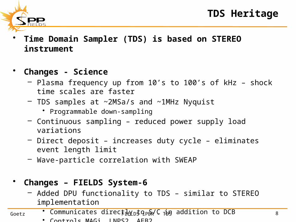
TDS Heritage
• Time Domain Sampler (TDS) is based on STEREO instrument
• Changes - Science– Plasma frequency up from 10’s to 100’s of kHz – shock time
scales are faster– TDS samples at ~2MSa/s and ~1MHz Nyquist
• Programmable down-sampling– Continuous sampling – reduced power supply load variations– Direct deposit – increases duty cycle – eliminates event length
limit– Wave-particle correlation with SWEAP
• Changes – FIELDS System-6– Added DPU functionality to TDS – similar to STEREO
implementation• Communicates directly to S/C in addition to DCB• Controls MAGi, LNPS2, AEB2• Communicates with SWEAP

Goetz 9FIELDS iPDR - TDS
Waveform and Particles
SamplesΔt = 500ns
CLK~2MHz
V(t)Δt = 500ns
count(t)

Goetz 10FIELDS iPDR - TDS
Waves and Particles
SamplesΔt = 500ns
V(t)Δt = 500ns
count(t)
t = 1,500ns t = 2,000ns t = 2,500ns t = 3,000ns t = 3,500ns t = 4,000ns t = 4,500ns t = 5,000ns
V = 0mV V = -2mV V = -4mV V = +5mV V = -12mV V = -15mV V = -10mV V = -5mV
n = 2 n = 4 n = 2 n = 2 n = 7 n = 3 n = 5
Goetz 11FIELDS iPDR - TDS
TDS Requirements
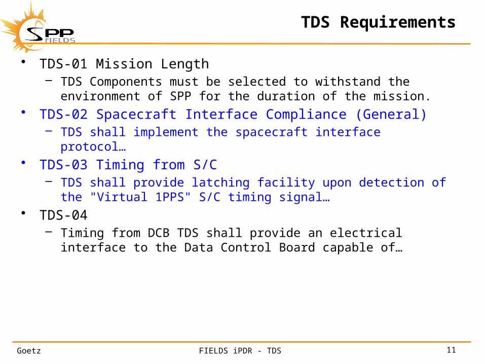
• TDS-01 Mission Length – TDS Components must be selected to withstand the
environment of SPP for the duration of the mission.• TDS-02 Spacecraft Interface Compliance (General)
– TDS shall implement the spacecraft interface protocol…• TDS-03 Timing from S/C
– TDS shall provide latching facility upon detection of the "Virtual 1PPS" S/C timing signal…
• TDS-04– Timing from DCB TDS shall provide an electrical interface to
the Data Control Board capable of…

Goetz 12FIELDS iPDR - TDS
SWEAP Requirements
• TDS-05 SWEAP Interface - CDI– TDS shall provide an electrical interface to the SWEAP
instrument capable of sending CDI commands, receiving CDI messages:
• [a] sending Command/Data Interface (CDI) messages to SWEAP;• [b] receiving SWEAP status and burst information from SWEAP;• [c] sending TDS time-keeping information;• [d] sending TDS clock synchronization.
• TDS-06 SWEAP Interface – Particles– TDS shall provide an electrical interface to the SWEAP
instrument capable of:• [a] receiving particle count information from SWEAP• [b] receiving particle synchronization and state information from
SWEAP

Goetz 13FIELDS iPDR - TDS
MAG Requirements
• TDS-07 MAG Interface – CDI– TDS shall provide an electrical interface to the MAG Electronics
capable of:• [a] setting control registers• [b] receiving MAG Science and Engineering data• [c] provide MAG AC heater synchronization

Goetz 14FIELDS iPDR - TDS
AEB Requirements
• TDS-08 Antenna Electronics Board Interface (AEB)– TDS shall provide an electrical interface to the Antenna
Electronics Board capable of:• [a] setting Biasing D/A converters and relays• [b] reading back the biasing voltages• [c] provide DC-DC converter synchronization
Goetz 15FIELDS iPDR - TDS
LNPS Requirements
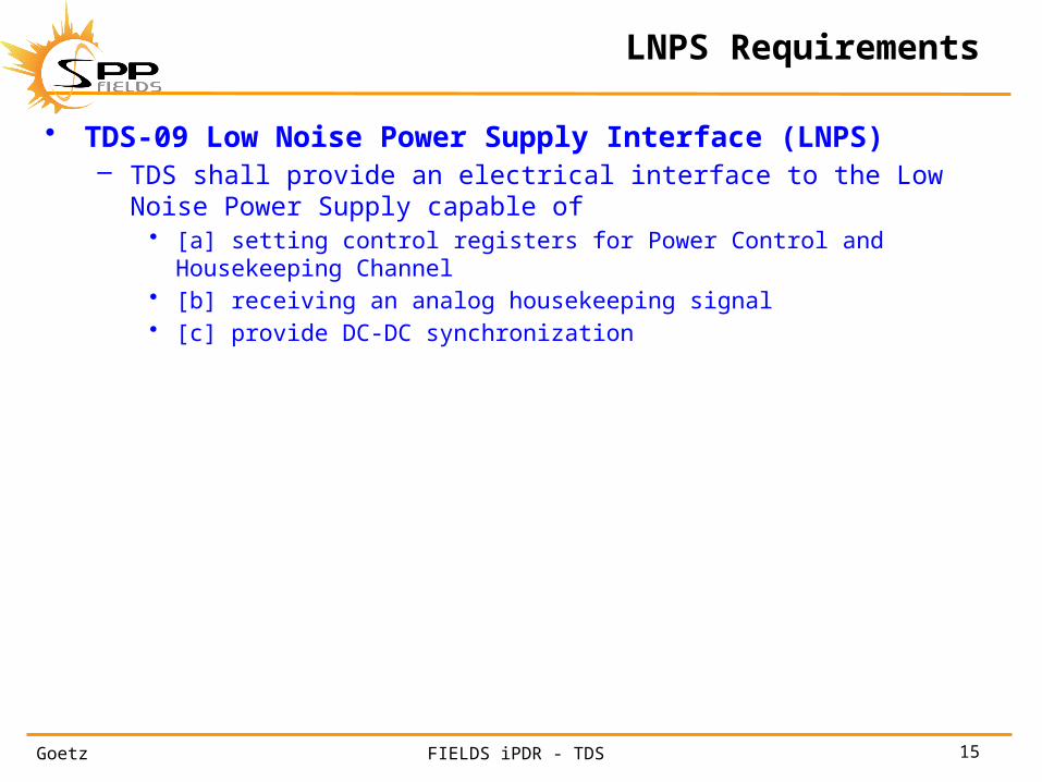
• TDS-09 Low Noise Power Supply Interface (LNPS)– TDS shall provide an electrical interface to the Low Noise
Power Supply capable of• [a] setting control registers for Power Control and Housekeeping
Channel• [b] receiving an analog housekeeping signal• [c] provide DC-DC synchronization

Goetz 16FIELDS iPDR - TDS
TDS Requirements
• TDS-10 Time Domain Sampler Control– TDS shall provide electrical interfaces to the Time Domain
Sampler data acquisition system capable of:• [a] setting TDS instrument modes• [b] receiving TDS instrument data
• TDS-11 TDS Memory Management– TDS shall include memory such that:
• [a] is capable of storing ~20 TDS snapshot events• [b] allows best available event to be sent to telemetry
• TDS-12 TDS Instrument Calibration– TDS analog science and analog housekeeping conversion
coefficients are determined and provided prior to S/C Integration to include gain, phase and timing

Goetz 17FIELDS iPDR - TDS
Science Requirements
• TDS-13 E Signals– TDS shall provide an electrical interface capable of:
• [a] signal processing and measurement of the low frequency component of E-Field signals
• TDS-14 E Signals– TDS shall provide an electrical interface capable of:
• [a] signal processing and measurement of the AC or plasma frequency (ranging to ~1MHz) component of E-Field signals."
• TDS-15 B Signals– TDS shall provide an electrical interface capable of:
• [a] signal processing and measurement of the AC or plasma frequency (ranging to ~1MHz) component of B-Field signals (single axis)."
• TDS-16 Instrument Calibration– TDS shall provide calibration parameters and algorithms so as
to allow conversion from telemetry units to physical units (gain and offset per channel) prior to S/C Integration.

Goetz 18FIELDS iPDR - TDS
TDS Block Diagram
Goetz 19FIELDS iPDR - TDS
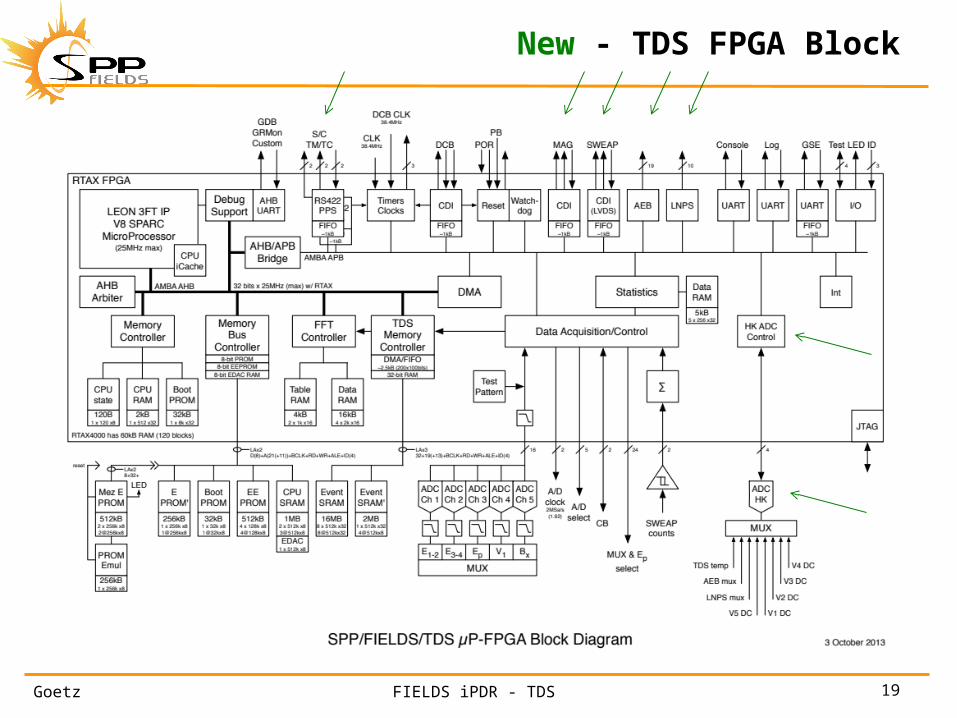
New - TDS FPGA Block

Goetz 20FIELDS iPDR - TDS
FIELDS block diagram
Goetz 21FIELDS iPDR - TDS
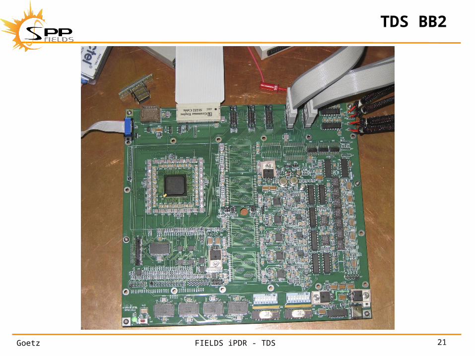
TDS BB2

Goetz 22FIELDS iPDR - TDS
TDS – Single Board Data Acquisition System
• Centers on RTAX4000 FPGA daughter board– Holds all logic, interfaces and LEON 3 processor instantiation
• TDS event data gathered by 16-bit ADCs at ~2MSa/s– Multiplexed 16-bit data bus
• Simultaneous acquisition of SWEAP particle counts• TDS event data stored directly into dedicated event
memory– 16MB event SRAM – 8 parts – 512k by 32bits– Circular buffers
• Processor support– 8-bit data bus
• Local SRAM w/ ECC• Local boot PROM (some in FPGA?)• Local program EEPROM
• S/C serial interfaces• CDI interfaces to DCB, MAG, SWEAP• Device interfaces – AEB, LNPS• Mezzanine interface
– Diagnostic UARTs

Goetz 23FIELDS iPDR - TDS
Configuration in Flight

Goetz 24FIELDS iPDR - TDS
Test Configuration at UMN

Goetz 25FIELDS iPDR - TDS
Resources
• TDS mass CBE is 435g (not counting structure)• TDS power CBE is 2.17W secondary• TDS bit-rate to DCB (flash) is ~10,000 b/s

Goetz 26FIELDS iPDR - TDS
Issues
• TDS design is well advanced– Based on earlier STEREO implementation– More than usual at this point (PDR)
• Selected ADC is great – but plastic– A cousin was used on STEREO– Putative parts have been obtained (x100)– Lead has been added– DPA has been completed (x5) well– Radiation and beam testing next– Up-screening after that– Backup solutions could be painful in performance and power– Astrium/ESA testing suggests we’ll be ok (only SEU/SEFI
sensitive)• Overall power
– We’re only now getting to good power estimates• LVDS protection solution is still open for S/C
communications
Goetz 27FIELDS iPDR - TDS
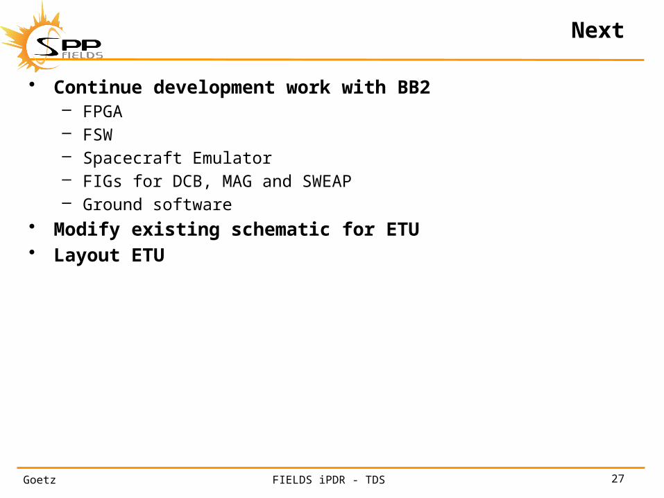
Next
• Continue development work with BB2– FPGA– FSW– Spacecraft Emulator– FIGs for DCB, MAG and SWEAP– Ground software
• Modify existing schematic for ETU• Layout ETU
Goetz 28FIELDS iPDR - TDS
SPP/FIELDSTime Domain Sampler FPGAPreliminary Design Review
Keith Goetz
University of Minnesota

Goetz 29FIELDS iPDR - TDS
TDS FPGA
• TDS is based on STEREO design– 3 STEREO FPGAs and 1 VLSI µP move into one FPGA for SPP
• TDS is a combination of analog electronics, digital electronics, VHDL firmware and flight software
• Added System-6 pieces fit in well– Low impact
• TDS FPGA is central
• RTAX4000 is the FPGA of choice• RTAX4000SL-1 CCGA-1272
– Maybe more than we need in gates but has lots of useable pins
• CQ352 does not have enough user pins– FIELDS FPGA daughter board makes this a common part/design
solution• Developed at UCB• Used in DCB, TDS and DFB• Risk reducer

Goetz 30FIELDS iPDR - TDS
TDS FPGA Block

Goetz 31FIELDS iPDR - TDS
TDS Data Acquisition/Control
• Gather time series data– Access ADCs– Front end processing
• Accumulate SWEAP counts and sync• Down sampling e-time series
– Send buffered data stream to TDS memory controller• Never skipping a beat
• Generate sampling clock• Select muxes

Goetz 32FIELDS iPDR - TDS
TDS statistics
• Peaks and maxes• Triggering• Langmuir wave statistics• Dust analysis
• High heritage
Goetz 33FIELDS iPDR - TDS
TDS Memory Control
• Accept data steam• Accept triggers• Control circular buffers
– Large dedicated 32-bit memory path– Large dedicated event memory (16MB)
• Interleave memory access from CPU

Goetz 34FIELDS iPDR - TDS
TDS FFT Controller
• Optional
• Allows frequency analysis– Redundancy– Enhances dynamic range of new all-digital TNR
• Large signal spectra
• Could be done in hardware or software

Goetz 35FIELDS iPDR - TDS
HK ADC Controller
• New
• Allow FSW access to external ADC/MUX– Analog HK– Analog Science

Goetz 36FIELDS iPDR - TDS
S/C TM/TC Interface
• New
• UARTS to/from S/C– A/B– S/C Time, Status and Sharing– S/C commands– S/C telemetry
• HK• MAGi
– Provides one real-time clock
– Common VHDL and FSW with DCB

Goetz 37FIELDS iPDR - TDS
Clocks
• Receive internal clock (from on-board oscillator)• Receive external clock (from DCB)• Fail-over and back
– Slave to DCB when possible
• Generate clocks for internal/external use– MAGi CDI (4.8MHZ) and heater (300kHz)– SWEAP CDI (4.8MHz) and high-rate clock (19.2MHz)– AEB2 conversion clock (300kHz)– LNPS2 conversion clock (600kHz)– ADC clocking
• Maintain real-time clock from S/C• Maintain real-time clock from DCB

Goetz 38FIELDS iPDR - TDS
Watchdog
• Handles resets• Internal watchdog timer
– Touched by FSW– If not touched delivers a reboot– Generally, the watchdog time is long
• 220s in the past – shorter here
Goetz 39FIELDS iPDR - TDS
DCB CDI
• Standard CDI slave interface• 4.8MHz• Also includes high rate clock (38.4MHz)• DCB sends TDS time and commands• TDS sends DCB fully formed/compressed TDS CCSDS
data packets– ~10kbps
• Common VHDL and FSW with DCB

Goetz 40FIELDS iPDR - TDS
MAG CDI
• New
• Standard CDI master interface• 4.8MHz• Also includes power supply chopping frequency
(300kHz)• TDS sends MAG time and commands• MAG sends TDS data chunks – one per cycle
• Common VHDL and FSW with DCB

Goetz 41FIELDS iPDR - TDS
SWEAP CDI
• New
• Standard CDI master interface– LVDS
• 4.8MHz• Also includes high rate clock (19.2MHz)• TDS sends SWEAP time and commands
– CBS– MAG vector– Once per cycle
• SWEAP sends contributions to CBS

Goetz 42FIELDS iPDR - TDS
AEB Interface
• New
• Parallel and serial interface lines• Controls Antenna Electronics Board parameters
– Current and voltage biasing• Retrieves AEB HK
– Controlling AEB MUX• Also includes power supply chopping frequency
(300kHz)
• Common VHDL and FSW with DCB
Goetz 43FIELDS iPDR - TDS
LNPS Interface
• New
• Parallel interface lines• Controls MAG power• Retrieves LNPS2 HK
– Controlling LNPS MUX• Also includes power supply chopping frequency
(600kHz)
• Common VHDL and FSW with DCB

Goetz 44FIELDS iPDR - TDS
Test UARTS
• Console– OOB commanding
• Log– OOB event stream
• GSE– OOB binary/packet data stream
• Debug
• Line drivers on GSE (mezz board)

Goetz 45FIELDS iPDR - TDS
Test points
• Board serial number• Blinking light
– Software controlled• Test input ports• Test output ports• I/O to EM connector to allow timing/triggering tests

Goetz 46FIELDS iPDR - TDS
Processor
• LEON 3 IP– Free – open source– SPARC V8– LEON 3 FT planned for flight– STEREO used an earlier version – SPARC V7
• IP– Gaisler GRLIB
• LEON• AHB/APB infrastructure• GDB• GRMON
– UARTs
Goetz 47FIELDS iPDR - TDS
Processor Support
• Interrupts• DMA Handler• Processor RAM
– Internal and external• Processor ROM/PROM
– Internal and external– Internal boot PROM?
• Processor EEPROM
Goetz 48FIELDS iPDR - TDS
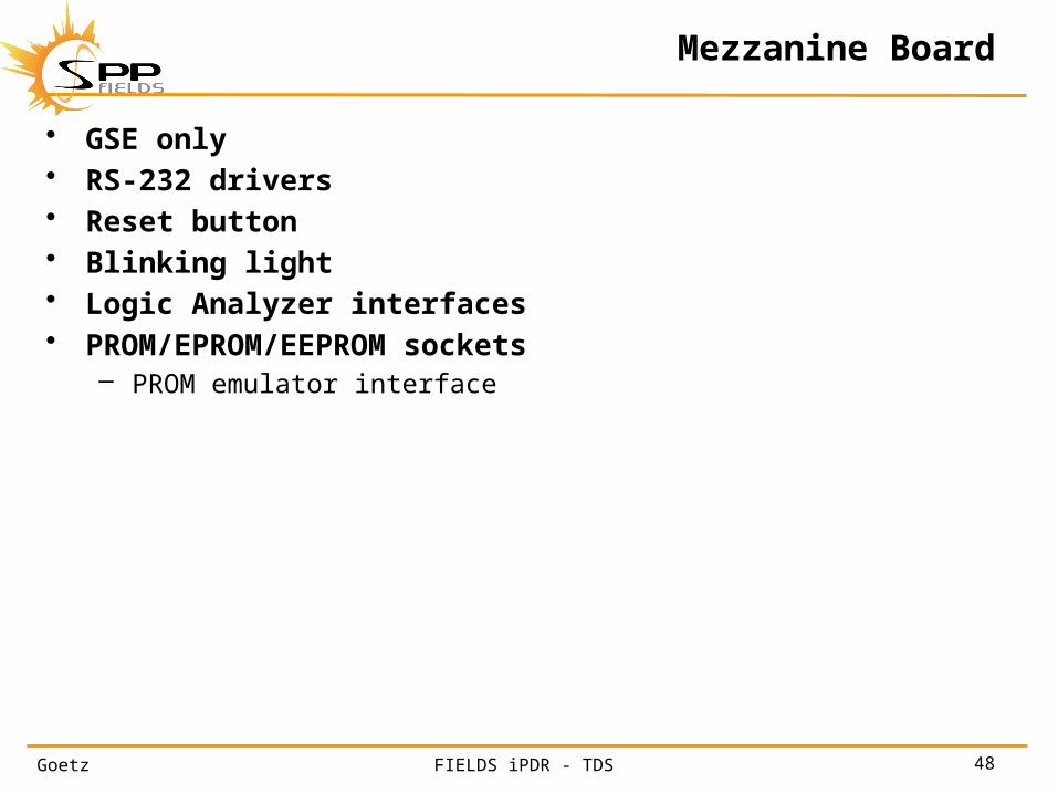
Mezzanine Board
• GSE only• RS-232 drivers• Reset button• Blinking light• Logic Analyzer interfaces• PROM/EPROM/EEPROM sockets
– PROM emulator interface
Goetz 49FIELDS iPDR - TDS
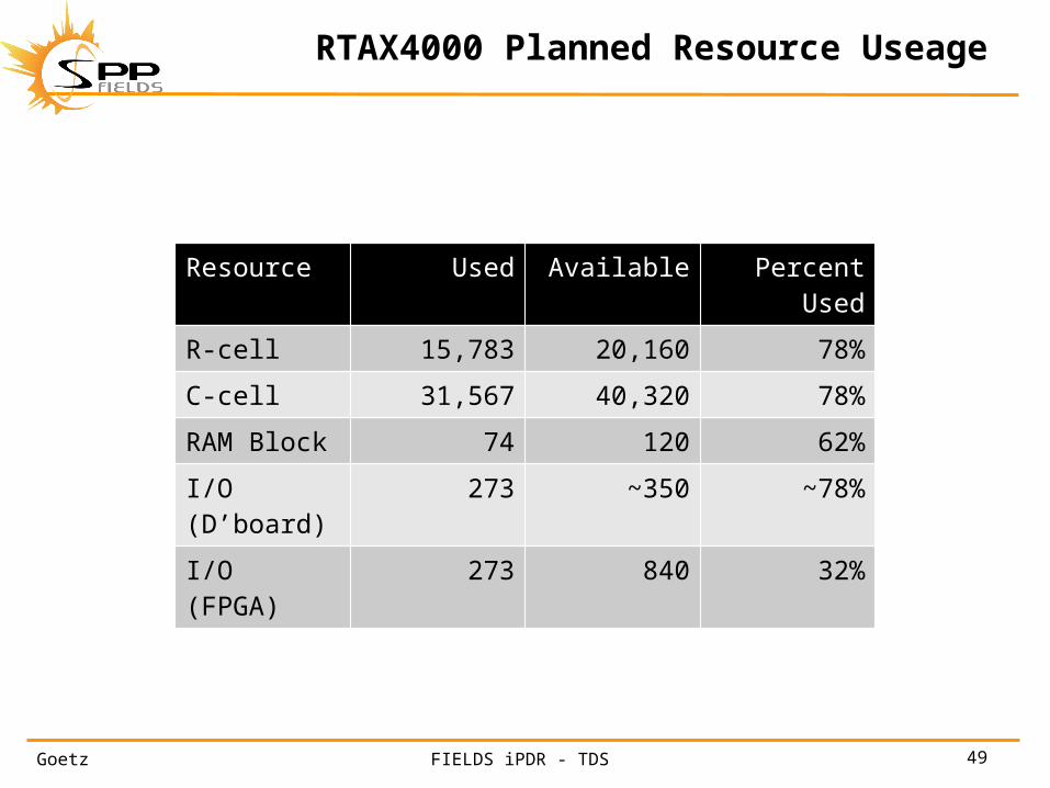
RTAX4000 Planned Resource Useage
Resource Used Available Percent Used
R-cell 15,783 20,160 78%
C-cell 31,567 40,320 78%
RAM Block 74 120 62%
I/O (D’board) 273 ~350 ~78%
I/O (FPGA) 273 840 32%

Goetz 50FIELDS iPDR - TDS
Peer Review Actions
No. Detailed Comment Response
1 Ceramic caps 0.1uF can be 0805 size, 0.01 can be 0603, all available from Presidio M123 line, 50V Ok
2 Use ECC on FPGA internal SRAM bits when they hold commands and control values Ok
3 Watchdog timer of 220 seconds is long. Consider if this could cause problems with spacecraft control. Could shorter timer work? Ok
4 Verify that you can get a FLASH FPGA version of the full fault protected version of LEON to reduce the risk of surprises when you program the first fuse-based FPGA. TBD
5 Talk to Analog Devices about the fabrication process of the AD7621 to clarify if the part is expected to be insensitive to radiation. Expedite a radiation test to reduce risk. Done
6 Show FPGA resource utilization Ok7 Add clock switching algorithm to FIELDS-SWEAP ICD. No
8 Verify the system for switching between clock sources (forward and back) does not violate any timing requirements (runt pulses, etc. Ok
9 Consider having common parts for SRAM to share resources / knowledge Ok10 Ask APL for new S/C interface temperatures ?

Goetz 51FIELDS iPDR - TDS
Issues
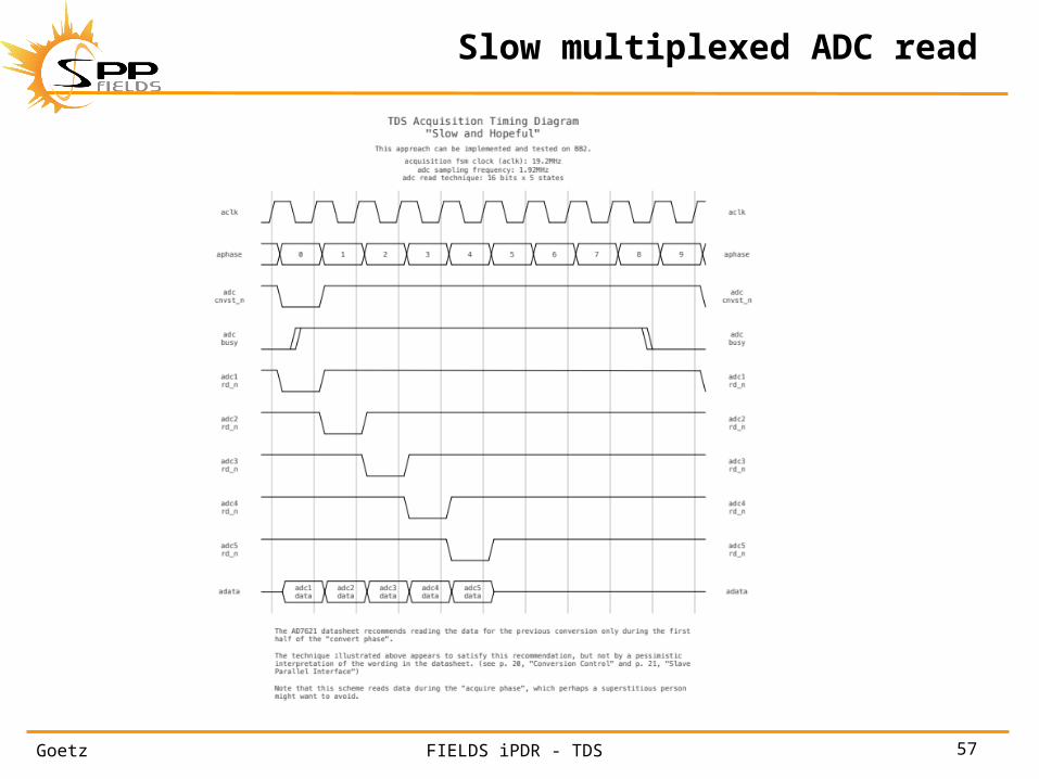
• ADC acquisition timing– Analysis of ADC read suggestions in AD data-sheet suggests
that reading the digital values from multiplexed bus is best constrained to a defined part of the acquisition cycle
– Testing will determine the actual requirement and margin– Alternative implementations exist
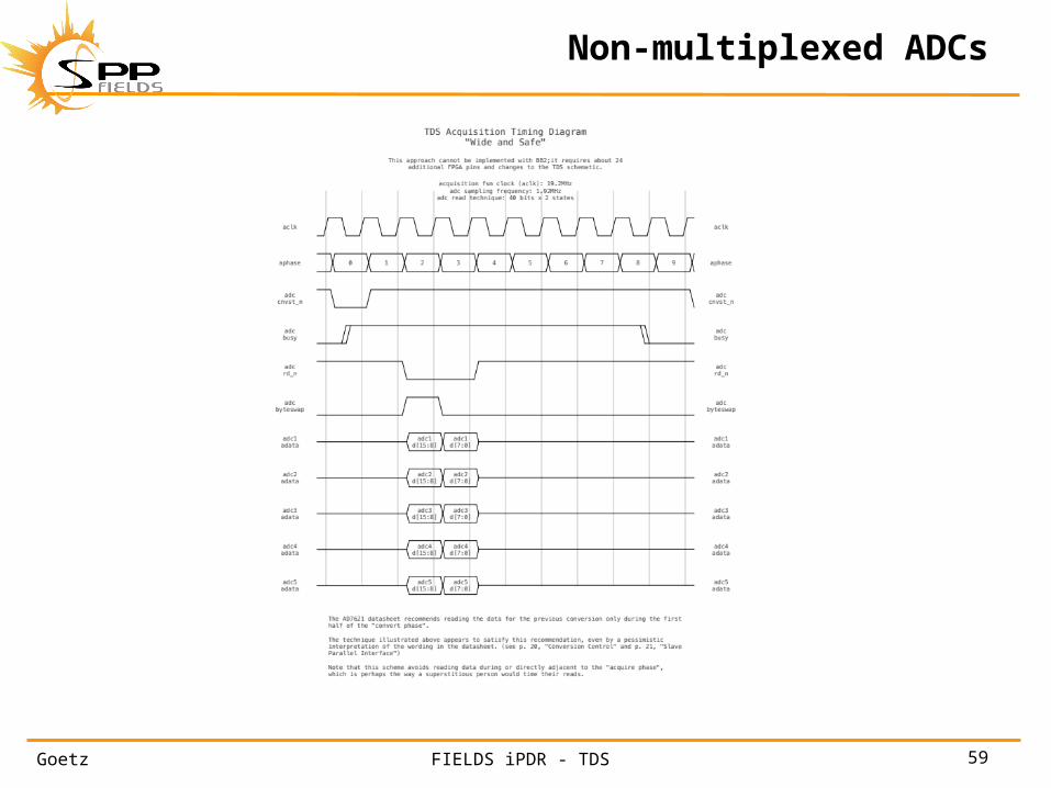
• Move the multiplexed acquisition to a faster clock• Move to a non-multiplexed ADC data bus
– Requires a change from BB2 implementation– Uses extra pins
• Use as is

Goetz 52FIELDS iPDR - TDS
Conclusion
• No serious issues• Experienced team with heritage starting point
– Some shared VHDL with UCB• Preliminary TDS hardware/firmware design meets or
exceeds requirements
• TDS hardware/FPGA is ready to move into ETU development
Goetz 53FIELDS iPDR - TDS
Backups

Goetz 54FIELDS iPDR - TDS
TDS Level 4 - part 1
Goetz 55FIELDS iPDR - TDS
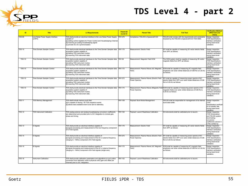
TDS Level 4 - part 2

Goetz 56FIELDS iPDR - TDS
FPGA statistics
Goetz 57FIELDS iPDR - TDS
Slow multiplexed ADC read

Goetz 58FIELDS iPDR - TDS
Faster ADC read clock
Goetz 59FIELDS iPDR - TDS
Non-multiplexed ADCs


