15
GOOD PRACTICE GUIDE AN INTRODUCTION TO PRODUCED WATER MANAGEMENT www.tuvnel.com
GOOD PRACTICE GUIDE
AN INTRODUCTION TO PRODUCED WATER MANAGEMENT
www.tuvnel.com
An Introduction to Produced Water Management
Contents Foreword 1
1 What is Produced Water? 2
2 Petroleum Hydrocarbons 2
3 What is Oil in Produced Water? 3
4 Down-hole Oil-in-Water Separation (DOWS) 4
5 Subsea Separation Systems 5
5.1 Gravity based 5
5.2 Cyclone based 6
6 Surface Treatment Technologies 6
6.1 Technologies for oil removal 6
6.2 Technologies for salt removal 7
Produced Water Re-injection (PWRI) 8
8 Oil-in-Water Monitoring 8
8.1 Officially approved methods 8
8.2 Bench top analysis methods 9
8.3 On-line monitoring 9
9 Oil in Produced Water Sampling 10
10 Oil-in-Water Legislation 11
10.1 History of the OSPAR discharge limit 12
10.2 Future legislation 12
11 Recommended Further Reading 13
Foreward
Produced water is a by-product of oil and gas production and with the increasing number of maturing fields water
production is on the increase worldwide. Estimates of the amount of produced water vary but could be in the region of
250 million barrels per day. Once produced water is separated from oil (and gas) it is treated and then discharged to surface
water or re-injected for either reservoir pressure maintenance or disposal. This document aims to provide an introduction to
the management of produced water discharges; including the chemical make-up of produced water, the various separation
and analysis technologies, together with current and future legislation.
1

1. What is Produced Water?
According to OSPAR (OSLO-PARIS) “Recommendation 2001/1” Produced Water means water which is produced in oil and/or
gas production operations and includes formation water, condensation water and re-produced injection water; it also includes
water used for desalting oil. Produced water is a complex mixture. It also has wide variations in composition within and
between reservoirs as well as with the age of fields. The following materials are generally associated with produced water:
• Dispersedhydrocarbons–oildropletsmainlyaliphatichydrocarbons
• Dissolvedhydrocarbons–aromaticandpolycyclicaromatichydrocarbons(PAHs)
• Solubleorganics:phenols,fattyacids
• Saltcontent
• Productionchemicals
• Heavymetals
• Radioactivematerials
2. Petroleum Hydrocarbons
Common everyday petroleum products such as petrol and diesel, for example, are derived from crude oil. Crude oil
is separated into constituent by a fraction distillation. The basic principle of this distillation process it that crude oil is
separated into the hydrocarbon fractions which have similar numbers of carbon atoms which relate, in turn, to similar
boiling points range. The most common petroleum fractions obtained from crude oil are given in the table below:
Fraction Carbon range Boiling range (°C)
Petrol C4-C12 25–200
Kerosene C10-C15 150–300
Diesel C12-C20 270–350
Lube Oil C20-C40 350 - 500
Asphalt C40+ > 500
These petroleum products comprise a complex mixture of hundreds of individual hydrocarbons that are principally grouped
into aliphatic, aromatic, and heterocyclic compounds.
Aliphatic hydrocarbons are those that contain alkanes, alkenes, and alkynes.
• Alkaneshavecarbonsjoinedbyasinglebond,theyarealsocalledsaturatedhydrocarbonsorparaffins.
They can be straight chained, e.g. methane, branched, e.g. isobutane, or cyclic, e.g. cyclopentane
• Alkeneshavecarbonsjoinedbyadoublebond,theyarealsocalledolefins,e.g.ethene
• Alkyneshavecarbonsjoinedbyatriplebond
Aromatic hydrocarbons are those that contain a benzene ring nucleus in their structure. They are grouped into two: the
monoaromatic hydrocarbons and the polyaromatic hydrocarbons, PAHs, which contain three or more aromatic rings. Two
ring aromatic hydrocarbons do not belong to either of them but in practice they are handled together with the PAHs.
Good Practice Guide
2
2. Petroleum Hydrocarbons cont.
Monoaromatic hydrocarbons contain one aromatic ring. The most interesting and common ones include Benzene (C6H6),
Toluene (C6H5-CH3), Ethylbenzene (C6H5-C2H5) and Xylene, C6H4-(CH3)2 often known as BETX by the industry. They are
volatile as well as have relatively high solubility in water.
The Polyaromatic Hydrocarbons, PAHs, cover a broad range of compounds. In environmental investigations it is common
to measure the sixteen PAHs defined by the list of Priority Pollutants from US EPA. These sixteen compounds are all full
aromatic hydrocarbons without any substitutes. In crude oil the major part of the PAH will be of the alkylated type.
Within OSPAR three alternative selections of most relevant Polyaromatic hydrocarbons have been suggested:
• Naphthalenes(alkylatedandnon-alkylated)
• NPDs:naphthalene,phenanthrene,dibenzothiophene(alkylatedandnon-alkylated),
which are 2-3 ring aromatic compounds
• US-EPAlistofsixteenPAHs(naphthalenes,phenanthrenesarepartofthesixteenUS-EPAPAHs,
dibenzothiophene is not)
When considering the aromatics, some, e.g. Oil and Gas Producers (OGP), have suggested the following grouping which
seems to be clearer:
• BETX:monocyclicaromaticcompounds
• NPD:2-3ringaromaticcompounds
• PAH:PolyaromaticcompoundsrepresentedbythesixteenUS-EPAPAHsexceptnaphthaleneandphenanthrene).
These are 3-6 ring aromatics compounds.
ItisgenerallyacceptedthattheBTEXandNPDpartitiontoagreaterdegreeintothedissolvedphase,whereasthePAHs
(excluding naphthalene and phenanthrene) are associated predominately with oil dispersed in the aqueous phase.
3. What is Oil in Produced Water?
According to OSPAR “Recommendation 2001/1” (which was amended by “Recommendation 2006/4”), oil means the total
hydrocarbons, which can be determined by the appropriate sum of analytical results obtained using the agreed reference
methods for dispersed oil and aromatic hydrocarbons.
The agreed reference method for dispersed oil is the method detailed in “Agreement 2005-15”, which is based on using
gas chromatography and flame ionisation detection (GC-FID).
Clearly it is crucial that one states precisely the definition and methodology used when referring to “oil”.
Dissolved-suchasBETX(e.g.Benzene,Ethyl-benzene,Toluene,andXylene),NPDsand/orsomeofthePAH(polycyclic
aromatic hydrocarbons)
An Introduction to Produced Water Management
3
3. What is Oil in Produced Water? cont.
Dispersed - in the form of small droplets, say in the range from 0.5 micron to 80 microns, some time referred to as
oil-in-water emulsion, which can be stable for a significant period of time.
Free oil- floating on the surface of water or in the forms of large droplets that will settle quickly
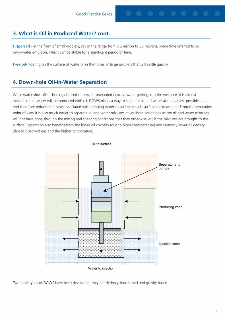
4. Down-hole Oil-in-Water Separation
While water shut-off technology is used to prevent unwanted / excess water getting into the wellbore, it is almost
inevitable that water will be produced with oil. DOWS offers a way to separate oil and water at the earliest possible stage
and therefore reduces the costs associated with bringing water to surface or sub-surface for treatment. From the separation
point of view it is also much easier to separate oil and water mixtures at wellbore conditions as the oil and water mixtures
will not have gone through the mixing and shearing conditions that they otherwise will if the mixtures are brought to the
surface. Separation also benefits from the lower oil viscosity (due to higher temperature) and relatively lower oil density
(due to dissolved gas and the higher temperature).
Two basic types of DOWS have been developed, they are Hydrocyclone-based and gravity based.
Good Practice Guide
4

4. Down-hole Oil-in-Water Separation
In the Hydrocyclone-based DOWS production fluids are drawn into the pump, which drives the fluids through the
separation module (cyclone). Oil and water are separated due to the centrifugal force; oil concentrate stream is then
lifted to the surface while the water stream is discharged from the underflow into an injection zone separated from the
production zone.
Gravity separation type DOWS are designed to essentially allow oil and water separation inside the well. Most gravity type
DOWS are vertically oriented with two openings, one in the oil layer and the other in the water layer. Using rod pumps, oil
is then lifted and water is injected. A schematic diagram of such gravity type DOWS with Rod Pump is shown in the figure
above. Both dual-action pumping (DAP) and triple-action pumping systems (TAPs) have been reported. The triple-action
pumping based systems achieve better water injection pressure compared to DAPs.
5. Sub-sea Separation Systems
A subsea separation system is designed to separate the multiphase fluids on the seabed and then send the oil and gas
streams with a minimum amount of water either together or using separate lines to the surface for further treatment.
Separated water may be re-injected back to formation either for disposal or for pressure maintenance. There are two main
subsea separation types. These are gravity based three phase subsea separation systems and cyclone based two phase
subsea separation systems.
5.1. Gravity based
A schematic diagram showing a gravity based subsea separation system is provided below.
An Introduction to Produced Water Management
5
5.1. Gravity based cont.
The basic design will include the following:
• Agravity(horizontalorvertical)separator
• waterinjectionfacilitiessuchasinjectionpumpandinjectionXmastree
• Achemicalinjectionsystemfortreatmentofemulsion,foamandcorrosionetc
• Asystemforsandseparationandremoval
• Asystemforpowertransmissionanddistribution
• Instrumentsforinjectionwaterqualitymonitoring,detectionofseparatorinterfacelevelsandemulsion
composition monitoring, and of course measurement of pressure and temperature.
5.2. Cyclone based
Gas Liquid Cylindrical Cyclones (GLCC) have become well established in the past decade for separation of gas and liquid
for the oil and gas industry. Cyclone based subsea separation systems use the same principle. One such system called
VASPS (Vertical Annular Separation and Pumping System) was developed in the 1990’s. This system enables high capacity
integrated separation and pumping equipment to be installed in a 30 to 36 inch conductor in a dummy well. In 2001 the
world’s first VASPS system was installed by Petrobras in Campos Basin.
6. Surface Treatment Technologies
Once produced water is brought to the surface onshore and offshore, whether it will be discharged into the environment
and or injected into underground for disposal and or reservoir pressure maintenance, treatment becomes critical.
There are two main categories when it comes to produced water treatment; these include treatment to remove oils
(dissolved and dispersed) and treatment to remove salt. Salt removal becomes crucial if the treated produced water were to
be re-used for e.g. irrigation, agriculture.
6.1. Technologies for oil removal
Oil in produced water exist in three forms; dissolved, dispersed and free oil as explained elsewhere in the guidance. Free oil
is relatively easy to separate. It is the dissolved and dispersed oil that is more difficult to remove.
There are many treatment technologies available for removing dispersed and dissolved oil from produced water. These
technologies include:
• Mechanical(gravity,enhancedgravity,gasflotation,filtration,membraneetc)
• Absorption/adsorption/extraction
(GranularActivatedCarbons–GAC,MacroPorousPolymerExtraction–MPPE;C-touretc)
• AdvancedOxidationProcess(AOP)
• Biological(bioreactors,wetlandsetc)
• Hybrid(combinationofvarioustechnologies,e.g.CompactFlotationUnits–CFUs)
Good Practice Guide
5 6
6.1. Technologies for oil removal
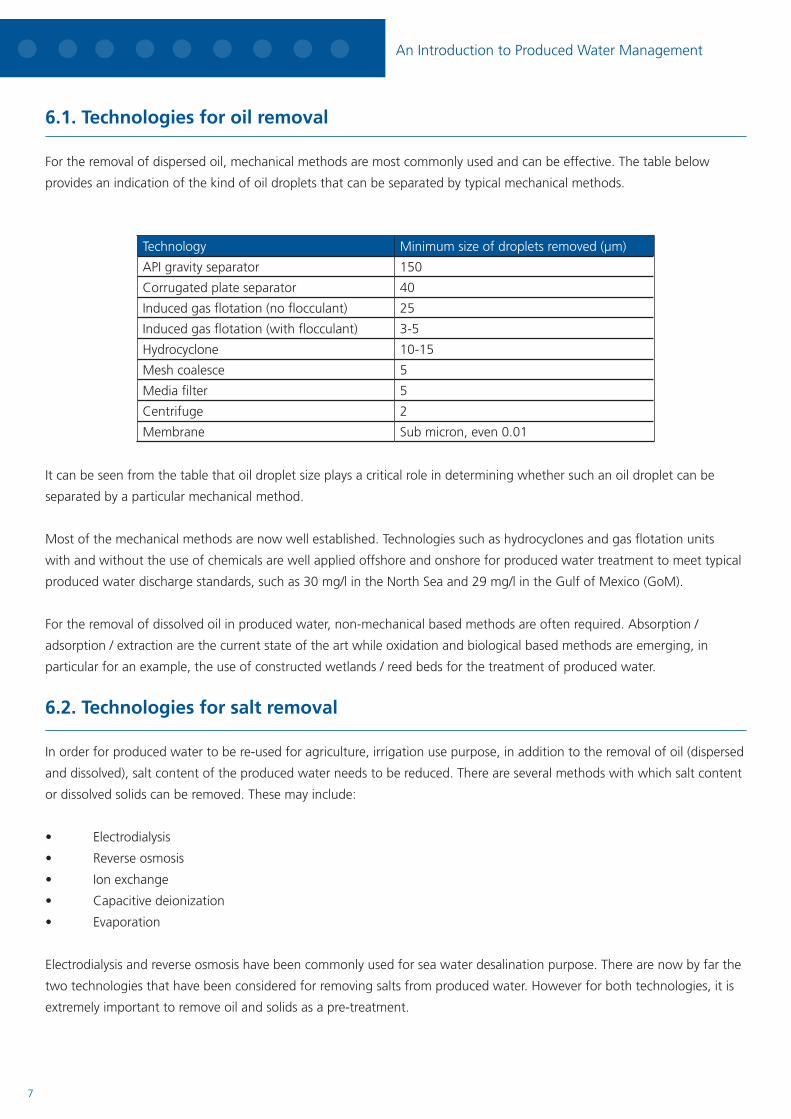
For the removal of dispersed oil, mechanical methods are most commonly used and can be effective. The table below
provides an indication of the kind of oil droplets that can be separated by typical mechanical methods.
Technology Minimum size of droplets removed (μm)
API gravity separator 150
Corrugated plate separator 40
Induced gas flotation (no flocculant) 25
Induced gas flotation (with flocculant) 3-5
Hydrocyclone 10-15
Mesh coalesce 5
Media filter 5
Centrifuge 2
Membrane Sub micron, even 0.01
It can be seen from the table that oil droplet size plays a critical role in determining whether such an oil droplet can be
separated by a particular mechanical method.
Most of the mechanical methods are now well established. Technologies such as hydrocyclones and gas flotation units
with and without the use of chemicals are well applied offshore and onshore for produced water treatment to meet typical
producedwaterdischargestandards,suchas30mg/lintheNorthSeaand29mg/lintheGulfofMexico(GoM).
For the removal of dissolved oil in produced water, non-mechanical based methods are often required. Absorption /
adsorption / extraction are the current state of the art while oxidation and biological based methods are emerging, in
particular for an example, the use of constructed wetlands / reed beds for the treatment of produced water.
6.2. Technologies for salt removal
In order for produced water to be re-used for agriculture, irrigation use purpose, in addition to the removal of oil (dispersed
and dissolved), salt content of the produced water needs to be reduced. There are several methods with which salt content
or dissolved solids can be removed. These may include:
• Electrodialysis
• Reverseosmosis
• Ionexchange
• Capacitivedeionization
• Evaporation
Electrodialysis and reverse osmosis have been commonly used for sea water desalination purpose. There are now by far the
two technologies that have been considered for removing salts from produced water. However for both technologies, it is
extremely important to remove oil and solids as a pre-treatment.
An Introduction to Produced Water Management
7
6.2. Technologies for salt removal cont.
With an increasingly stringent regulatory requirements worldwide and an emphasis on water re-use in particular in places
where water is increasingly becoming scarce, oil and gas producers around the globe are increasingly having to treat
produced water to remove dissolved oil, dissolved solids on top of dispersed oil.
7. Produced Water Re-injection (PWRI)
PWRI is a very important produced water management option. It offers the following advantages:
• Achievezerodischargetoseainaphysicalsense
• Playasignificantroleinmeetingregulatoryrequirementsofproducedwaterdischargetosea
• Possiblybeusedforreservoirpressuremaintenance
PWRIhasbeeninpracticeformanyyears;however,NorthSeahasoneofthelowestratiosofre-injectionwatertothetotal
produced water in the world. In 2003 while most of offshore produced water is re-injected in the Middle East, and almost
halfinNorthAmerica,and45%inAfrica,only12%ofoffshorewaterproducedinoilandgasproductionwasre-injected
byaroundfortyinstallationsor18%oftotalnumberofinstallationsthatarepermittedtodischargeproducedwater.
PWRI is a truly transverse topic between reservoir, process and well engineering. There are many aspects that one needs to
consider in making PWRI reliable, effective and economical.
8. Oil-in-Water Monitoring
Oil in produced water is by far the most important parameter that has been commonly used for regulating the discharge
of produced water offshore. Therefore analysis and monitoring is extremely important for both offshore operators and
regulators. From the operators’ point of view the monitoring of oil in produced water is not only important in terms of
meetingthedischargelimit(30mg/lcurrentlyintheNorthSea),butalsointermsofprocesscontrolandmanagement.
8.1. Officially approved methods
Details of the OSPAR approved reference method can be found in the OSPAR agreement 2005-15. The method was
implementedfromJanuary2007acrosstheNorthSeacountries.Essentially,themethodinvolvesn-pentanetoextract
oils from a produced water sample. This is then followed by a clean-up with florisil to remove polar components in the
pentane extract, and then analysing using GC and FID. The measured dispersed oil by the method is defined as the sum
of concentrations of compounds extractable with n-pentane, not absorbed on florisil and which may be chromatographed
with retention times between those of n-heptane (C7H16) and n-tetracontane (C40H82) excluding the concentrations of the
aromatic hydrocarbons of toluene, ethlybenzene and the three isomers of xylene.
Good Practice Guide
8
8.2. Bench top analysis methods
For routine offshore oil-in-water analyses, simple bench-top analysis methods are very useful. There are a good number of
methods/techniques that are available. These may include
• ColorimetricMethod
• FibreOpticChemicalSensor
• InfraredAnalysisBasedonInternalReflection
• UVAbsorbance
• UVFluorescence
• SupercriticalFluidExtraction(SFE)andIR
• SolidPhaseExtraction(SPE)withIR/GC-FID/GC-MS
CurrentlyintheNorthSeabothIRabsorptionwithinternalreflectionandUVfluorescencemethodshavebeenused.In
NorwayandDenmarkIRabsorptionwithinternalreflectionmethodisnowpermittedbytheauthorityforreporting.InUK
both methods have been tested or are under test offshore. A new method based on using Supercritical Fluid Extraction and
Infrared (SFE-IR) has been recently developed for the analysis of oil-in-water. The method effectively allows the continuation
of the old IR method but without the use of the banned solvents such as Freon.
8.3. On-line monitoring
One of the key advantages for using an on-line oil-in-water monitor is that it can provide oil-in-water information
continuously. Therefore, from the process control and management point of view it is extremely useful.
There are many techniques that may be used for constructing an on-line oil-in-water monitor. These techniques include:
• Focusedultrasonicacoustics
• Fibreopticalchemicalsensor
• Imageanalysis
• Lightscatteringandturbidity
• On-linesolventextractionandIRanalysis
• Infraredattenuationtotalreflection
• Photoacousticsensor
• Laserinducedfluorescence
• Spectralfluorescentsignatures
• UVfluorescence
• UVabsorption
Mostofon-lineoil-in-watermonitoringinstrumentsthatarecurrentlyusedorareundertrialsintheNorthSeaarebased
on light scattering and UV fluorescence. Light scattering based instruments measure the dispersed oils. They are also widely
used as oil content meters for monitoring ship bilge water discharges. The main disadvantages associated with this type of
instruments include its sensitivity to gas bubbles, solids and also fouling of the sample window. For UV fluorescence based
instruments, it is vital that the ratio of aromatic to the total hydrocarbons in the produced water remains relatively constant.
Overall the use of UV fluorescence based instruments is on the increase. This is partly as a result of instrument suppliers
being able to use the most appropriate detection wavelength that is specifically linked to the Polycyclic Aromatic
An Introduction to Produced Water Management
9

8.3. On-line monitoring cont.
Hydrocarbons (PAH), which can be unique for specific installations. The content of PAHs is now well known to be closely
related to the dispersed oils.
With the recent OSPAR decision to recommend a new reference method based on a modified version of the ISO 9377 GC-
FID and the fact that such a method for direct offshore use is practically difficult. It is recognised that alternative methods
such as on-line monitoring and bench top methods may need to be widely allowed for the analysis of oil-in-water for the
purpose of reporting.
9. Oil in Produced Water Sampling
In many parts of the world, oil in produced water is a key parameter that is used for compliance monitoring. It is also a
parameter that is used by operators for process control. Provision of accurate oil in produced water data is therefore very
important for both regulators and oil and gas producers.
To obtain accurate oil in produced water data, an important step of the process is to withdraw a representative sample
from the main produced water pipeline. Without a representative sample, even with the best sample handling procedure
and fully complied analysis method, the results can be erroneous.
To obtain a representative oil in produced water sample care has to be taken in relation to the following:
• Selection of a sample point location: This will depend on whether the samples to be taken will be used for
operational or regulatory compliance monitoring purpose. In the case of regulatory compliance, this must be
chosen at a location immediately after the last item of the produced water treatment equipment in or downstream
of, a turbulent region, but before dilution.
• Design of a sample point: Ideally a sample point is installed on a vertical up-flow pipe with the probe facing
upstream. The probe should be of a centre line pitot, which should be made using stainless steel tubing or other
suitable material. The pitot should be of at least ½” bore with the edges of the pitot smoothened. If a sample
point is fitted into a horizontal pipe, the probe should ideally face upstream.
• Flow mixing conditions: This is particularly important if the sample point is installed on a horizontal pipe.
Adequate mixing that will result in good dispersion across the pipe cross section needs to be provided prior to the
sample point.
• Isokinetic sampling: Due to a density difference between oil and water, it is important that the samples are taken
iso-kinetically. Isokinetic sampling means that samples are taken where the linear velocity of fluids in the sampling
tube (probe) is the same as that in the main pipeline.
• Other points: When taking a sample, if the sample point is not in continuous use, then adequate flushing is
carried out prior to taking a sample. As a minimum, it is advised that the sample point should be flushed for one
minute. For external valving at the sample point, there will normally be a requirement for double block and bleed
valving. Also the distance between the sample probe and the sample valving should be kept at a minimum.
Online oil in produced water monitoring is increasingly used for process trending and optimisation. Online monitors may be
fitted inline or onto a side-stream depending upon the instrument supplied and or space available. If such an instrument is
fitted inline (no by-pass), then it is important that the location chosen must have adequate mixing.
Good Practice Guide
10
9. Oil in Produced Water Sampling cont.
When such a device is fitted onto a by-pass stream, the feed to the monitor should have a dedicated sample connection. A
centre line pitot together with isokinetic sampling should be used to ensure samples taken are representative.
Until recently, there has been little information and emphasis on oil in produced water sampling due to the fact that
produced water has been considered as a waste stream which generates no revenue. The publication of OSPAR and UK
guidanceonthesubject,forwhichNELplayedaveryimportantroleindraftingup,hashelpedtheNorthSeaoiland
gas industry a great deal in terms of a harmonised sampling and measurement approach, to obtain more accurate oil in
produced water data.
10. Oil-in-Water Legislation
International Law recognises four categories of water discharges associated with the operation of offshore platforms:
• Platformdrainagefrommachineryspace-includinggenerators,fueltanksandpumpsetc
• Offshoreprocessingdrainage-openandcloseddrainagefromoilandgasprocessingactivities
• Producedwaterdischarge-separatedfromproductionfluids
• Displacementdischarge-usedandseparatedfromseparationstorage
The first of these is regulated under the provision of the International Convention for the Prevention of Pollution from Ships
1973, as amended 1978 (MARPOL 73/78). The UK is a signatory to the Convention and implements its provisions through
the Merchant Shipping (Prevention of Oil Pollution) Regulations 1983. These regulations, as amended, will require that all
installations meet an oil-in-water concentration of 15 ppm for platform drainage discharges, and that they be fitted with
the appropriate monitoring and separation technology to ensure compliance. The three remaining discharges are regulated
undertheprovisionsoftheOSPARConventionfortheprotectionofthemarineenvironmentoftheNorth-EastAtlantic,
which entered into force on 25 March 1998. This is implemented under UK law by the Oil Pollution Prevention and Control
(OPPC) Regulations 2005. These regulations have been designed to encourage offshore operators to continue to reduce the
quantities of hydrocarbons discharged during the course of offshore operations. The Regulations give the definition of oil,
introduce a permitting system for oil discharges and strengthen powers to inspect and investigate oil discharges.
With regard to the discharge of oil in produced water in the UK, it was stipulated that the monthly average concentration
of dispersed oil in produced water did not exceed the 40 mg/l during the period between permit issued on 31 December
2005, and did not exceed 30 mg/l after 1 January 2006. The maximum concentration of dispersed oil in the discharge
should not exceed 100 mg/l. In terms of sampling requirements, for installations that discharge no greater than two tonnes
of dispersed oil per annum, samples should be collected at least once a month at approximately equal intervals of time. For
the installations that discharge more than two tonnes per annum, at least two samples are required to be taken at equal
intervals of time. Oil concentration should be determined by a method as prescribed by the UK Department of Energy and
Climate Change (DECC) (solvent extraction and GC-FID analysis) or an alternative method approved by DECC.
An Introduction to Produced Water Management
11
10.1. History of the OSPAR discharge limit
The Oslo-Paris (OSPAR) Convention was adopted on 22 September 1992, primarily in order to merge the 1972 Oslo
Convention for the Prevention of Marine Pollution by Dumping from Ships and Aircraft and the 1974 Paris Convention for
the Prevention of Marine Pollution from Land-based Sources.
Currently the signatories to OSPAR are
• Belgium
• Denmark
• EuropeanCommunity
• Finland
• France
• Germany
• Iceland
• Ireland
• Luxembourg
• TheNetherlands
• Norway
• Portugal
• Spain
• Sweden
• Switzerland
• UnitedKingdom
The OSPAR Convention entered into force on 25 March 1998.
10.2. Future legislation
With OSPAR clearly decided on the new reference method for the determination of dispersed oil in produced water,
detailed legislation on how to implement the new reference method at both OSPAR and national levels will be made
available. Also with the new reference method of having limited practicality for offshore applications, it was clear that an
alternative method for both on-line and laboratory bench-top instruments would need to be developed. Acceptance criteria
forsuchalternativemethodsweredevelopedandmadeavailablewiththeassistanceofNEL.
Whileoil-in-waterwillremainanimportantparameterforthemanagementofproducedwaterintheNorthSea,arisk
based approach is now being established by OSPAR. It is likely that such an approach based on whole effluent assessment
will be in place in 2011.
Good Practice Guide
11 12

11. Recommended Further Reading
• “OSPARRecommendation2001/1forthemanagementofproducedwaterfromOffshoreInstallations”,
www.ospar.org
• OSPARAgreement2005-15–“Samplingandanalysisprocedureforthe40mg/ltargetstandard”,www.ospar.org
• OSPARAgreement2006-6,“Oilinproducedwateranalysis–guidelineoncriteriaforalternativemethod
acceptance and general guidelines on sample taking and handling”, www.ospar.org
• GuidanceNotesforthesampling&analysisofproducedwater&otherHydrocarbonDischarges–August2010–
Version 2.1 https://www.og.decc.gov.uk/environment/opaoppcr_guide.htm
• J.D.Arthuretal,“Technicalsummaryofoil&gasproducedwatertreatmenttechnologies”,Draft,March2005.
http://www.rrc.state.tx.us/commissioners/williams/environment/produced_water_trtmnt_Tech.pdf
• OGPReport,“Aromaticsinproducedwater:occurrence,fate&effects,andtreatment“,
http://www.ogp.org.uk/pubs/324.pdf
• OGPReport,“Guidelinesforproducedwaterinjection”,http://www.ogp.org.uk/pubs/302.pdf
An Introduction to Produced Water Management
For further information, contact:
TUVSUDNEL,EastKilbride,GLASGOW,G750QF,UK
Tel: + 44 (0) 1355 220222 Email: [email protected] www.tuvnel.com


