Digital Commons @ George Fox University Digital Commons @ George Fox University Faculty Publications - Biomedical, Mechanical, and Civil Engineering Department of Biomedical, Mechanical, and Civil Engineering 2000 Governing Yield Modes for Common Bolted and Nailed Wood Governing Yield Modes for Common Bolted and Nailed Wood Connections Connections Brian J. Tucker Washington State University David Pollock George Fox University, [email protected]Kenneth J. Fridley University of Nevada, Las Vegas Jeffrey J. Peters Washington State University Follow this and additional works at: https://digitalcommons.georgefox.edu/mece_fac Part of the Civil Engineering Commons, Structural Engineering Commons, and the Structural Materials Commons Recommended Citation Recommended Citation Tucker, Brian J.; Pollock, David; Fridley, Kenneth J.; and Peters, Jeffrey J., "Governing Yield Modes for Common Bolted and Nailed Wood Connections" (2000). Faculty Publications - Biomedical, Mechanical, and Civil Engineering. 38. https://digitalcommons.georgefox.edu/mece_fac/38 This Article is brought to you for free and open access by the Department of Biomedical, Mechanical, and Civil Engineering at Digital Commons @ George Fox University. It has been accepted for inclusion in Faculty Publications - Biomedical, Mechanical, and Civil Engineering by an authorized administrator of Digital Commons @ George Fox University. For more information, please contact [email protected].
Transcript
Digital Commons @ George Fox University Digital Commons @ George Fox University
Faculty Publications - Biomedical, Mechanical, and Civil Engineering
Department of Biomedical, Mechanical, and Civil Engineering
2000
Governing Yield Modes for Common Bolted and Nailed Wood Governing Yield Modes for Common Bolted and Nailed Wood
Kenneth J. Fridley University of Nevada, Las Vegas
Jeffrey J. Peters Washington State University
Follow this and additional works at: https://digitalcommons.georgefox.edu/mece_fac
Part of the Civil Engineering Commons, Structural Engineering Commons, and the Structural Materials
Commons
Recommended Citation Recommended Citation Tucker, Brian J.; Pollock, David; Fridley, Kenneth J.; and Peters, Jeffrey J., "Governing Yield Modes for Common Bolted and Nailed Wood Connections" (2000). Faculty Publications - Biomedical, Mechanical, and Civil Engineering. 38. https://digitalcommons.georgefox.edu/mece_fac/38
This Article is brought to you for free and open access by the Department of Biomedical, Mechanical, and Civil Engineering at Digital Commons @ George Fox University. It has been accepted for inclusion in Faculty Publications - Biomedical, Mechanical, and Civil Engineering by an authorized administrator of Digital Commons @ George Fox University. For more information, please contact [email protected].
GOVERNING YIELD MODES FOR COMMON BOLTED AND NAILED
WOOD CONNECTIONS
By Brian J. Tucker,1 Student Member, ASCE, David G. Pollock,2 Member, ASCE,Kenneth J. Fridley,3 Member, ASCE, and Jeffery J. Peters4
ABSTRACT: Connections in wood structures are important when designing for ductility. The 1997 UniformBuilding Code has taken this into consideration when designating wind and earthquake load duration factors forconnections. Factors of 1.6 or 1.33 may be applied to the connection strength, depending on the type of yieldmode exhibited by the connection, which may be determined from the yield limit equations supplied in theNational Design Specification for Wood Construction (NDS). The NDS provides the designer with multipletables containing capacities for various common connections. Unfortunately, yield modes are not published alongwith tabulated capacities. Therefore, the designer must carry out potentially cumbersome calculations using theNDS yield limit equations simply to determine the governing yield mode before an appropriate Uniform BuildingCode load duration factor can be applied. In this paper, several NDS tables are extended to include capacityand yield mode, smaller side member thickness configurations are added to the existing nail/spike tables, and auseful toe-nail table is provided. The overall purpose of these tables is to accelerate the design process byeliminating time-consuming calculations.
INTRODUCTION
Due to the need for ductile performance of a structure, con-nections may be one of the most important engineered aspectsof light-frame wood construction. Connection ductility is es-sential for maintaining structural integrity during dynamicloading events such as wind and earthquakes.
Capacity of a given connection may be obtained from yieldlimit equations, which are presented in the National DesignSpecification for Wood Construction (NDS) (‘‘ANSI/AF&PA’’1997). Yield mode equations for the capacity of bolted con-nections and nail/spike connections are included in NDS chap-ters 8 and 12, respectively. Bolted connection equations areseparated into two categories: single shear and double shear.One set of equations is required for nail/spike connectionssince they are typically only used in single shear configura-tions. The nominal design value of the connection, Z, is de-termined by taking the least value calculated from the appro-priate set of yield mode equations. The mode correspondingto the least value is referred to as the yield mode of the con-nection (for example, Im, Is, II, IIIm, IIIs, IV). The various yieldmodes are illustrated in Appendix I of the NDS and duplicatedhere in Fig. 1. Yield modes Im and Is are the result of woodfibers crushing in the main and side members, respectively.Yield mode II is the result of wood fiber crushing in bothmembers, which allows the fastener to rotate. This is often dueto oversized bolt holes. Mode II is not applicable to bolteddouble shear or nail/spike connections. Yield modes IIIm andIIIs are the result of fastener yielding, wherein a plastic hingeis formed at the shear plane, along with wood fiber crushingprimarily in the main member or side member, respectively.Mode IV is also a result of fastener yielding, in which multipleplastic hinges are formed.
1Grad. Res. Asst., Dept. of Civ. and Envir. Engrg., Washington StateUniv., Pullman, WA 99164-2910.
2Asst. Prof., Dept. of Civ. and Envir. Engrg., Washington State Univ.,Pullman, WA.
3Prof., Dept. of Civ. and Envir. Engrg., Washington State Univ., Pull-man, WA.
4Grad. Res. Asst., Dept. of Civ. and Envir. Engrg., Washington StateUniv., Pullman, WA.
The strength of wood connections depends not only on ma-terial properties (such as wood bearing strength and fastenerbending yield strength) and connection geometry (such asmember dimensions and fastener diameter), but also on theduration of the load applied to the connection. Wood has theproperty of exhibiting greater strength for shorter durationloads than for longer, sustained loads. The NDS addresses thistime-dependent behavior of wood by applying a load durationfactor, CD, to the capacity of the connection. For load com-binations, including short-duration loads such as wind or earth-quake, the NDS prescribes a load duration factor of 1.6 to beapplied to the capacity of all connections. However, the Uni-form Building Code (UBC) (1997) prescribes load durationfactors that differ slightly from the NDS with regard to theseloading conditions. The UBC permits a load duration factorof 1.6 to be used for connections exhibiting yield modes IIIm,IIIs, or IV when the loading is due to wind or earthquake. Alower load duration factor of 1.33 must be used when yieldmodes Im, Is, or II are exhibited. The primary reason for thisdiscrepancy is the difference in the amount of cyclic test dataavailable for each yield mode. Recent laboratory tests ofmodes III and IV connections have revealed sufficient ductilityunder cyclic loading (Dolan et al. 1995, 1996). This is theresult of inelastic fastener deformation and yielding, whichlead to energy dissipation in the connection. The lack of datafor modes I and II under cyclic loading conditions has led toconcerns about the ductility of these connections and aboutthe UBC-imposed limitation on the load duration factor.
The NDS contains several bolt and nail/spike connectiondesign tables with yield capacities for multiple configurations.Unfortunately, these tables do not indicate the governing yieldmode. A designer could use the NDS yield limit equations todetermine the mode of connection yield or, more conserva-tively, always use a load duration factor of 1.33 when design-ing to resist wind or seismic loads, according to the UBC.However, from an economic standpoint, there is a need toknow which yield mode governs the connection behavior.
In addition to yield modes, the NDS tables of connectiondesign values do not address some common connection con-figurations. For example, the tables for nail/spike connectionvalues in chapter 12 of the NDS do not address side memberthickness values below 12.7 mm (0.5 in.). These connectioncapacities and yield modes would be useful for shear wall anddiaphragm design where thin sheathing is used. Toe-nail con-nections are commonly used in light-frame construction; how-ever, design tables for these connections are not included in
FIG. 1. Connection Yield Modes (Adapted from American Forest and Paper Association 1997)
TABLE 1. Percentages of Applicable Yield Modes for NDSBolted Connection Tables
the NDS. This paper addresses these limitations in the NDSconnection tables.
SCOPE
The purpose of this paper is to evaluate governing yieldmodes for bolted and nailed connections commonly used inwood construction. NDS tables are extended, providing boththe capacity and the governing yield mode. Additional nailedconnection values and yield modes are tabulated for smallerside member thicknesses. Tables are also created presentingthe design strength for toe-nailed connections as a useful ad-dition to the existing NDS design tables.
DESIGN TABLES AND EXAMPLES
Tables provided herein present a limited number of speciesand member sizes. A more comprehensive set of tables isavailable from the authors.
Bolted Connections
Various governing yield modes are applicable throughoutthe NDS bolted connection design tables and are not neces-sarily intuitive. This state of affairs presents a need for boltedconnection yield mode tables for efficient structural design.Otherwise, to accurately use the UBC load duration factors, adesigner must calculate the yield mode using the NDS boltedconnection equations simply to determine the mode. The NDSyield mode equations are provided in the appendix to thispaper.
Not all yield modes are applicable in all bolted connectionconfigurations. For example, modes II and IIIm do not pertainto double shear bolted connections. In addition, mode Is doesnot pertain to bolted connections with steel side plates. Theapplicable modes for different bolted connection configura-tions are summarized in Table 1. Slightly over 50% of the
bolted connection configurations in the NDS tables exhibityield modes of either Im, Is, or II. Therefore, a slight majorityof the connections are considered by the UBC to be ‘‘non-ductile,’’ requiring a designer to use the lesser load durationfactor of 1.33. The percentages of each applicable yield modein the NDS bolt tables are summarized in Table 1. Tables 2–7 provide tabulated design values and modes for various boltedconnection configurations.
Bolted connection tables were created for some commonconnection configurations, including single and double shearconnections with wood and steel side members. As an exampleof table usage, consider the following connection configura-tion, illustrated in Fig. 2:
• Double shear connection• Load applied parallel to main member and perpendicular
to side members• All members are spruce-pine-fir• 38.1 mm (1-1/2 in.) side member thickness• 88.9 mm (3-1/2 in.) main member thickness• 15.9 mm (5/8 in.) diameter ASTM A307 bolt• Seismic loading conditions
TABLE 2. Bolt Design Values (Z ) and Yield Modes for Single Shear (Two Member) Connections for Sawn Lumber with Both Membersof Identical Species
TABLE 3. Bolt Design Values (Z ) and Yield Modes for Single Shear (Two Member) Connections for Sawn Lumber with Both Membersof Identical Species
TABLE 4. Bolt Design Values (Z ) and Yield Modes for Single Shear (Two Member) Connections for Sawn Lumber with 1/40 ASTM A36Steel Side Plate
TABLE 5. Bolt Design Values (Z ) and Yield Modes for Double Shear (Three Member) Connections for Sawn Lumber with Both Mem-bers of Identical Species
TABLE 6. Bolt Design Values (Z ) and Yield Modes for Double Shear (Three Member) Connections for Sawn Lumber with Both Mem-bers of Identical Species
TABLE 7. Bolt Design Values (Z ) and Yield Modes for Double Shear (Three Member) Connections for Sawn Lumber with 1/40 ASTMA36 Steel Side Plate
FIG. 2. Bolted Double Shear Connection
Using Table 6, entitled ‘‘Bolt Design Values (Z) and YieldModes for Double Shear (Three Member) Connections,’’ forsawn lumber with both members of identical species, the con-nection yield capacity, Zs', and yield mode are found to be3.69 kN (830 lb) and Is, respectively. According to the UBC,for a mode Is connection, a load duration factor, CD, of 1.33may be used to obtain the tabulated connection capacity forseismic loading. The factored design capacity, Z9, is the re-sulting product, as follows:
Z9 = Z C = (3.69)(1.33) = 4.91 kNs D'
[Z9 = Z C = (830)(1.33) = 1,104 lb]s D'
For comparison of UBC and NDS design procedures, the al-lowable connection capacity for seismic loading, according tothe NDS, is as follows:
Z9 = Z C = (3.69)(1.6) = 5.90 kNs D'
[Z9 = Z C = (830)(1.6) = 1,328 lb]s D'
If a 12.7 mm (1/2 in.) diameter ASTM A307 bolt is usedinstead of the 15.9 mm (5/8 in.) diameter bolt, a connectionyield capacity and yield mode of 2.85 kN (640 lb) and IIIs,respectively, are obtained again from Table 6. For this yieldmode, the 1.6 load duration factor may be applied to the de-sign capacity of the connection for both UBC and NDS designprocedures. The result is as follows:
Z9 = Z C = (285)(1.6) = 4.55 kNs D'
[Z9 = Z C = (640)(1.6) = 1,024 lb]s D'
This demonstrates that a smaller bolt diameter does not nec-essarily result in a significantly lower design capacity due tothe UBC use of the 1.33 load duration factor, instead of the1.6 factor, for ‘‘nonductile’’ connections.
Nailed Connections
Tables 8–10 were created with yield capacities and yieldmodes for common wire nails, box nails, and threaded hard-ened-steel nails for connections with both members of thesame species. The existing NDS nail/spike tables were ex-panded to include smaller side member thickness configura-
tions. All NDS tabulated nail/spike configurations with metalside plates exhibit mode III yielding; therefore, they were notreplicated here. For weak species with small side memberthicknesses, yield mode Is was more prominent when com-pared with larger side member thickness configurations. Forexample, common wire nail connections consisting of spruce-pine-fir members with a 7.94 mm (5/16 in.) side memberthickness primarily exhibit mode Is yielding, as presented inTable 9. This pattern is very obvious for common wire spikeconnections; and this information may be valuable for shearwall design. For example, consider the shear wall connectionillustrated in Fig. 3.
• 10d common nail• 7.94 mm (5/16 in.) plywood• 51 mm by 102 mm (2 by 4) stud• Both members are spruce-pine-fir (to demonstrate changes
in yield mode)
For wall diaphragm design, the diaphragm factor (Cdi = 1.1)may be used. By referring to Table 9, entitled ‘‘Common WireNail Design Values (Z) for Single Shear (two member) Con-nections,’’ the design capacity and yield mode for the con-nection are 311 N (70 lb) and Is, respectively. The allowableconnection capacity can then be calculated according to theUBC as follows:
Z9 = ZC C = (311)(1.33)(1.1) = 455 ND di
[Z9 = ZC C = (70)(1.33)(1.1) = 102.4 lb]D di
If a thicker side member is used, such as 9.53 mm (3/8 in.)plywood, the design capacity and yield mode are 316 N (71lb) and IIIs, respectively. The allowable design capacity is thencalculated as follows:
Z9 = ZC C = (316)(1.6)(1.1) = 556 ND di
[Z9 = ZC C = (71)(1.6)(1.1) = 123.2 lb]D di
By using a thicker side member, yielding of the connection isgoverned by mode IIIs instead of mode Is, which allows thehigher load duration factor of 1.6 to be used, according toUBC design procedures.
Toe-Nailed Connections
Toe-nail connection values are not dependent upon actualside member thickness, but instead on the fastener length ineach member. For the toe-nail design table, the toe-nail factor,Ctn, of 0.83 was applied to the nominal design capacity, aswell as the penetration depth factor Cd. All toe-nailed connec-tions presented in Table 11 exhibit a yield mode of IIIs or IV.Therefore, a load duration factor of 1.6 may be applied, usingeither NDS or UBC design procedures. Consider a wall stud(side member) to bottom plate (main member) toe-nail con-nection, as illustrated in Fig. 4 with an additional nail insertedon the opposite side of the wall stud:
• Wall stud to bottom plate connection• All members are southern pine• Two 10d common nails
The nominal design capacity, Z*, and yield mode are found inTable 11 to be 427 N (96 lb) and IV, respectively. Nominaldesign capacity is the result of the connection capacity mul-tiplied by the toe-nail factor and the penetration depth factor,as follows:
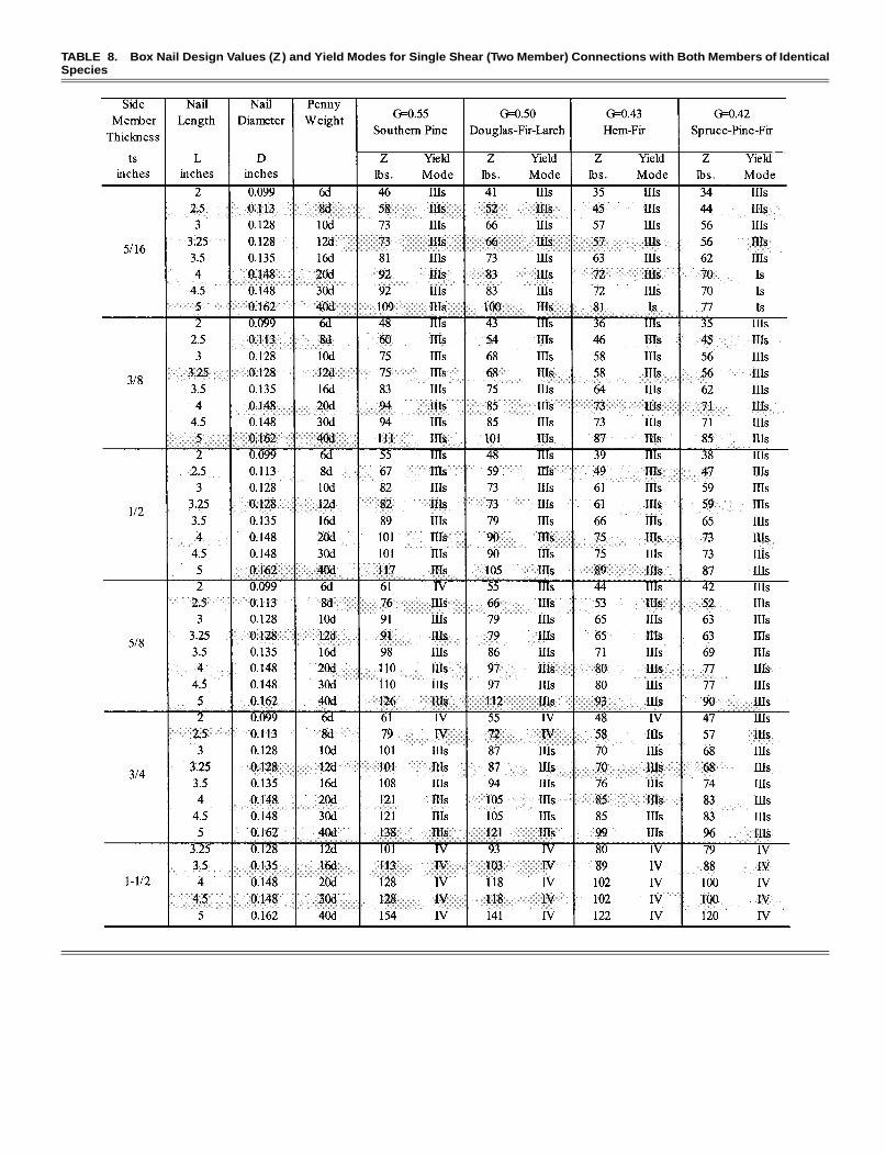
TABLE 8. Box Nail Design Values (Z ) and Yield Modes for Single Shear (Two Member) Connections with Both Members of IdenticalSpecies
TABLE 9. Common Wire Nail Design Values (Z ) and Yield Modes for Single Shear (Two Member) Connections with Both Members ofIdentical Species
TABLE 10. Threaded Hardened-Steel Nail Design Values (Z ) and Yield Modes for Single Shear (Two Member) Connections with BothMembers of Identical Species
FIG. 3. Sheathing to Stud Wall Connection
TABLE 11. Design Values (Z *) and Yield Modes for Laterally Loaded, Toe-Nailed Connectionsa,b with Both Members of Identical Spe-cies
Z* = ZC C = (427)(0.83)(0.9) = 319 Ntn d
[Z* = ZC C = (128)(0.83)(0.9) = 96 lb]tn d
Since the connection exhibits a mode IV yielding, a load du-ration factor of 1.6 may be multiplied by the nominal designcapacity, Z*, to obtain the allowable design capacity, Z9 asfollows:
Z9 = Z*C = (319)(1.6) = 510 ND
[Z9 = Z*C = (96)(1.6) = 154 lb]D
Thus, for two 10d common nails, the capacity would be 1.02kN (308 lb).
For toe-nails and slant nailing subjected to seismic loading,the Structural Engineers Association of California (SEAOC)
FIG. 4. Toe-Nail Diagram (Adapted from Breyer et al. 1999)
recommends limiting the design capacity of toe-nailed con-nections to 2.189 kN/m (150 lb/ft). This limitation applies toforces being transferred from diaphragms to shear walls, dragstruts (collectors), or other elements, or from shear walls toother elements (Recommended 1996). The rationale behindthis recommendation is based on shrinkage of blocking orclose nail spacing, which might cause a weakened plane forwood splitting. This recommendation is also appropriate dueto the difficulty of toe-nail installation and inspection.
SUMMARY
NDS bolted connection tables were modified to include thegoverning yield mode for the tabulated connection capacity.The NDS tables were also expanded to include additional sidemember thicknesses as well as the yield modes for each tab-ulated connection capacity. Toe-nail tables were created that
present the nominal connection capacity and the yield mode.The nominal capacity is the result of multiplying the calculatedconnection capacity by the toe-nail factor and the penetrationdepth factor, when applicable. Using these tables alleviates theneed for lengthy capacity and yield mode calculations. Thisallows the designer to quickly determine whether the connec-tion behaves in a ductile or nonductile manner, according tothe 1997 NDS. The appropriate load duration factor for windand earthquake loading of 1.6 or 1.33 may then be applied tothe strength of the connection in accordance with the 1997UBC provisions. The following are general trends to be re-membered when designing ductile connections:
• A decrease in fastener diameter, D, moves from brittle toductile modes.
• An increase in side member thickness, ts, or main memberthickness, tm, moves from brittle to ductile modes.
• An increase in wood dowel bearing strength, Fe, movesfrom brittle to ductile modes.
Even in the absence of a quantitative advantage associatedwith ductile connections (for example, 1997 UBC CD = 1.6versus 1.33), it is recommended that designers in regions ofhigh seismic activity specify ductile connection yield modesrather than brittle yield modes since this can facilitate greaterstructural deformations without catastrophic failure in overloadscenarios. From a practical standpoint, this may involve de-signing with a larger number of small diameter fasteners, inlieu of a few large diameter fasteners.
A more comprehensive set of bolt and nail/spike tables isavailable from the authors. These include more of the species,thicknesses, and connectors listed in the NDS tables.
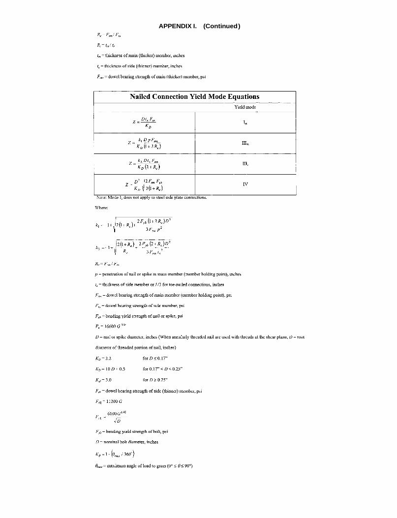
APPENDIX I.
APPENDIX I. (Continued )
APPENDIX II. REFERENCES
‘‘ANSI/AF&PA NDS—1997 National Design Specification for woodconstruction.’’ (1997). American Forest & Paper Association, Wash-ington, D.C.
Breyer, D. E., Fridley, K. J., and Cobeen, K. E. (1999). Design of woodstructures, 4th Ed., McGraw-Hill, New York.
Dolan, J. D., Gutshall, S. T., and McLain, T. E. (1995). ‘‘Monotonic andcyclic tests to determine short-term load duration performance of nailand bolt connections, Vol. I: Summary report.’’ Rep. No. TE-1994-001,Timber Engrg. Ctr., Virginia Polytechnic Institute and State University,
Blacksburg, Va.Dolan, J. D., Gutshall, S. T., and McLain, T. E. (1996). ‘‘Determination
of short-term duration-of-load performance of nailed and bolted con-nection using sequential phased displacement tests, Vol. I: Summaryreport.’’ Rep. No. TE-1994-003, Timber Engrg. Ctr., Virginia Polytech-nic Institute and State University, Blacksburg, Va.
Recommended lateral force requirements and commentary, 6th Ed.(1996). Structural Engineers Association of California (SEAOC) Seis-mology Committee.
Uniform building code. (1997). International Conference of Building Of-ficials (ICBO), Whittier, Calif.