GOVERNMENT ENGINEERING COLLEGE DAHOD APPLIED MECHANICS DEPARTMENT B.E. II (CIVIL) (FOURTH SEMESTER) 2018-2019 SUBJECT: STRCTURAL ANALYSIS - I Subject code: 2140603 Name of student: Enrollment no: Faculty conveyer, 1. Prof. B. M. Purohit 2. Prof Y K Tandel 3. Prof. N. B. Umravia 4. Prof M. A. Shaikh 5. Prof R. A. Jhumarwalla
Transcript
GOVERNMENT ENGINEERING COLLEGE DAHOD
APPLIED MECHANICS DEPARTMENT
B.E. II (CIVIL) (FOURTH SEMESTER)
2018-2019
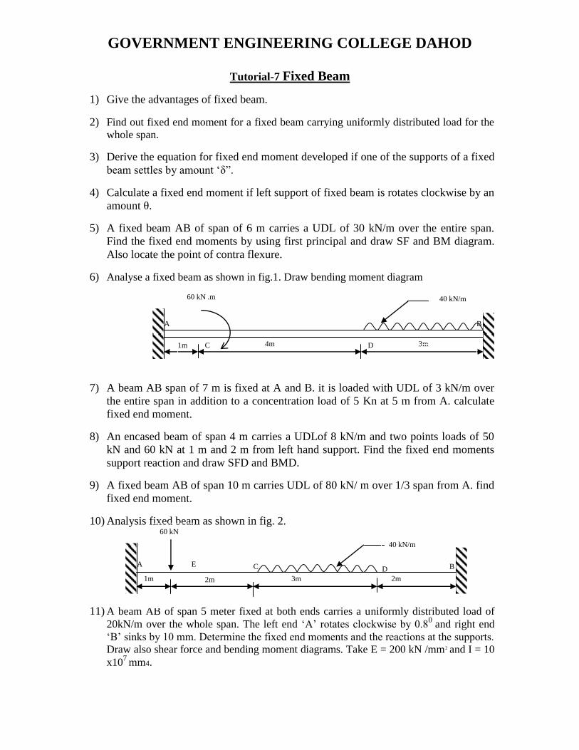
SUBJECT: STRCTURAL ANALYSIS - I
Subject code: 2140603
Name of student:
Enrollment no:
Faculty conveyer,
1. Prof. B. M. Purohit
2. Prof Y K Tandel
3. Prof. N. B. Umravia
4. Prof M. A. Shaikh
5. Prof R. A. Jhumarwalla
GOVERNMENT ENGINEERING COLLEGE DAHOD
Applied Mechanics department
April- 2019
CERTIFICATE
This is to certify that the Mr /Miss_____________________________
_____________________________________ of BE – II year 4th
Semester
class Enrollment No ______________________ and Exam No
__________________
Has satisfactorily completed his / her Term work in “Structural
Analysis- I 2140603) for the term ending in April 2019
Date:_______________
Sign of Teacher
Head of the Department
GOVERNMENT ENGINEERING COLLEGE DAHOD
APPLIED MECHANICS DEPARTMENT
2018- 2019
NAME :_______________________________________________________
Roll No :__________________ Enroll No: ___________________
YEAR: - BE I (4th
Semester) Civil
Subject: “Structural Analysis - I” (2140603)
SR.
NO
COURSE CONTENT Page DATE GRADE SIGN REMARK
1. Tutorial -1
Fundamentals of Statically
Determinate Structures:
2. Tutorial -2
Displacement of Determinate
Beams and Plane Truss:
3. Tutorial -3
Direct and Bending stresses:
4. Tutorial -4
Columns and Struts:
5. Tutorial -5
Arches, Cables and Suspension
Bridges:
6. Tutorial -6 Thin cylinder:
7. Tutorial -7
Fixed Beams & Consistent
Deformation Method:
8. Tutorial -8
Strain Energy
GOVERNMENT ENGINEERING COLLEGE DAHOD
Tutorial – 1 FUNDAMENTALS OF STATICS
1. Define statically determinate and indeterminate structures.
2. Distinguish between statically determinate and indeterminacy of the structures
3. Explain „degree of static indeterminacy‟.
4. Explain maxwell‟s theorem of reciprocal deflection.
5. Defined „kinematics indeterminacy of a structure‟ Explain with sketches.
6. State and Explain Principle of Superposition with suitable example.
7. Define statically determinate and indeterminate structures.
8. Differentiate between the terms: BEAM, TRUSS, FRAME and ARCH.
9. “Indeterminate structures are better than determinate structures” Comment on the
statement.
10. Find static indeterminacy and kinematic indeterminacy of structures given in below
figure.
11. Explain and prove Maxwell‟s reciprocal theorem with example.
12. Find SI and KI for the structures shown in fig.1 to 20.
Fig. 1 Fig. 2
Internal hinge
Fig. 3 Fig. 4
Internal hinge A
B C D
E
Fig. 5
A B
C D
Fig. 6
A B C D
Fig. 7
A B C
D
E Internal hinge
GOVERNMENT ENGINEERING COLLEGE DAHOD
Fig. 8
Internal hinge
Fig. 9
Fig. 10
Fig. 11
Fig. 13 Fig. 14 Fig. 15 Fig. 16
Fig. 17 Fig. 18 Fig. 19
GOVERNMENT ENGINEERING COLLEGE DAHOD
TUTORIAL-2
DISPLACEMENT OF DETERMINATE BEAMS & PLANE TRUSS
1. Relation between slope deflection and radius of curvature.
2. Defined Macauli‟s method.
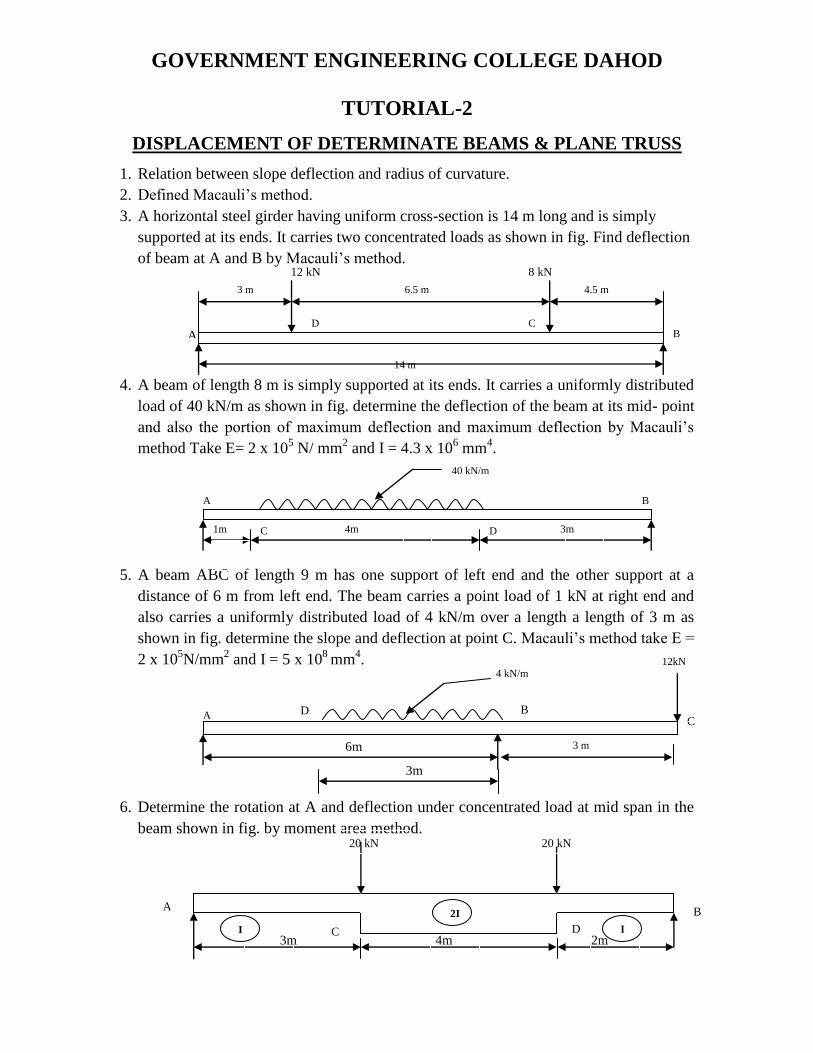
3. A horizontal steel girder having uniform cross-section is 14 m long and is simply
supported at its ends. It carries two concentrated loads as shown in fig. Find deflection
of beam at A and B by Macauli‟s method.
4. A beam of length 8 m is simply supported at its ends. It carries a uniformly distributed
load of 40 kN/m as shown in fig. determine the deflection of the beam at its mid- point
and also the portion of maximum deflection and maximum deflection by Macauli‟s
method Take E= 2 x 10⁵ N/ mm
2 and I = 4.3 x 10
6 mm
4.
5. A beam ABC of length 9 m has one support of left end and the other support at a
distance of 6 m from left end. The beam carries a point load of 1 kN at right end and
also carries a uniformly distributed load of 4 kN/m over a length a length of 3 m as
shown in fig. determine the slope and deflection at point C. Macauli‟s method take E =
2 x 10⁵N/mm
2 and I = 5 x 10
8 mm
4.
6. Determine the rotation at A and deflection under concentrated load at mid span in the
beam shown in fig. by moment area method.
A
6m 3 m
4 kN/m
3m
C
12kN
D B
A
C D
B
40 kN/m
4m 3m 1m
20 kN 20 kN
A
C D
B
I
2I
I 3m 4m 2m
8 kN
12 kN
14 m
C
A B D
6.5 m 4.5 m 3 m
GOVERNMENT ENGINEERING COLLEGE DAHOD
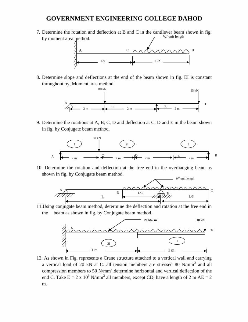
7. Determine the rotation and deflection at B and C in the cantilever beam shown in fig.
by moment area method.
8. Determine slope and deflections at the end of the beam shown in fig. EI is constant
throughout by, Moment area method.
9. Determine the rotations at A, B, C, D and deflection at C, D and E in the beam shown
in fig. by Conjugate beam method.
10. Determine the rotation and deflection at the free end in the overhanging beam as
shown in fig. by Conjugate beam method.
11.Using conjugate beam method, determine the deflection and rotation at the free end in
the beam as shown in fig. by Conjugate beam method.
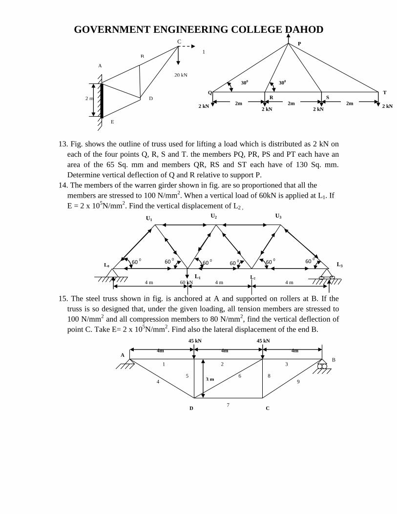
12. As shown in Fig. represents a Crane structure attached to a vertical wall and carrying
a vertical load of 20 kN at C. all tension members are stressed 80 N/mm2 and all
compression members to 50 N/mm2.determine horizontal and vertical deflection of the
end C. Take E = 2 x 10⁵ N/mm
2 all members, except CD, have a length of 2 m AE = 2
m.
L/
2
W/ unit length
A C B
L/2 L/2
80 kN 25 kN
2 m 2 m 2 m
A
B C D
2 m
m 2 m
m 2 m
m
60 kN
I 2I I
2 m 2 m 2 m 2 m A B D C E 2 m 2 m 2 m 2 m
L/3
D
A C
W/ unit length
B
L L/3
20 kN/ m 10 kN
2I I
B A
1 m 1 m
GOVERNMENT ENGINEERING COLLEGE DAHOD
13. Fig. shows the outline of truss used for lifting a load which is distributed as 2 kN on
each of the four points Q, R, S and T. the members PQ, PR, PS and PT each have an
area of the 65 Sq. mm and members QR, RS and ST each have of 130 Sq. mm.
Determine vertical deflection of Q and R relative to support P.
14. The members of the warren girder shown in fig. are so proportioned that all the
members are stressed to 100 N/mm2. When a vertical load of 60kN is applied at L1. If
E = 2 x 10⁵N/mm
2. Find the vertical displacement of L2 ,
15. The steel truss shown in fig. is anchored at A and supported on rollers at B. If the
truss is so designed that, under the given loading, all tension members are stressed to
100 N/mm2 and all compression members to 80 N/mm
2, find the vertical deflection of
point C. Take E= 2 x 10⁵N/mm
2. Find also the lateral displacement of the end B.
1
2 m
A
B
E
20 kN
D
C
2 kN 2 kN 2 kN
300 300
P
Q R S
T
2 kN 2m 2m 2m
4 m 60 kN 4 m L1
U1 U2 U3
L3
60 0 60
0 60
0 60
0 60 0 60
0
L2
L0
4 m
8
2 1
4 5 6
3
9
7
4m 4m 4m
45 kN 45 kN
B
3 m
A
D C
GOVERNMENT ENGINEERING COLLEGE DAHOD
Tutorial – 3 DIRECT & BENDING STRESSES
1. Explain limit of eccentricity and core of a section.
2. Distinguish between direct stresses and bending stresses.
3. Defined the kernel of a section. Obtain core of a Rectangular, Hollow rectangular,
circular, hollow circular section.
4. Limit of eccentricity defined in different sections Rectangular, Hollow rectangular,
circular, hollow circular.
5. A hallow rectangular masonry pier is 1.2 m X 0.8 m wide and 150 mm thick a
vertical load of 2 MN is transmitted in vertical plane bisecting 1.2 m side and at
an eccentricity of 100 mm from geometric axis of section. Calculate maximum.
and minimum stress intensities in section.
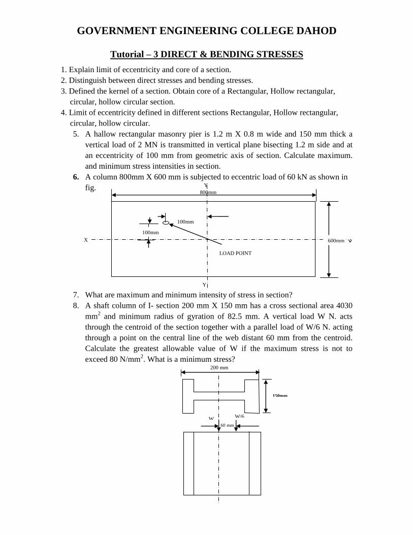
6. A column 800mm X 600 mm is subjected to eccentric load of 60 kN as shown in
fig.
7. What are maximum and minimum intensity of stress in section?
8. A shaft column of I- section 200 mm X 150 mm has a cross sectional area 4030
mm2 and minimum radius of gyration of 82.5 mm. A vertical load W N. acts
through the centroid of the section together with a parallel load of W/6 N. acting
through a point on the central line of the web distant 60 mm from the centroid.
Calculate the greatest allowable value of W if the maximum stress is not to
exceed 80 N/mm2. What is a minimum stress?
100mm
Y
Y
X X
800mm
100mm
600mm
LOAD POINT
60 mm
150mm
W/6 W
200 mm
GOVERNMENT ENGINEERING COLLEGE DAHOD
9. A 20 m height masonary chimney is 2 m square at base and trapper to 1 m square
at top the tapped central flue is circular in cross- section and 1 m diameter at the
base. If the total weight of the brick work, about the base is 1300 kN find for what
uniform intensity of wind pressure an one face of chimney the stress distribution
the base just ceases to be wholly compressive.
10. A masonry dam of rectangular cross section 10 m high and 5 m wide has water up
to the top and its one side. If weight density of masonry is 21.582 kN /m2. Find
max. & min. stresses intensities at the base of dams.
11. A masonry trapezoidal Dam 4m. High, 1 m wide at its top and 3m. Wide at
bottom retains water and its vertical force. Determine the max. And min.
stresses.(a) When the reservoir is full (b) When the reservoir is empty. Take
weight density of masonary as 19.62 kN/m3.and of water as 10 kN/m
3.
12. A masonry dam of trapezoidal section is 10 m high. It has a top width of 1.5 m
and a bottom width of 6.5 m. The water face of the dam has a better of 1 in 10. If
the water level is at the top of the dam, find the maximum and the minimum
normal stresses at the base. Masonry weighs 22500 N/m3. And water weighs 9810
N/m3.
13. A mass concrete dam has a trapezoidal cross-section. The height above the
foundation is 64 m and its water face is vertical. The width at the top is 4.5 m.
calculate the necessary minimum width of the dam at its bottom, to ensure that no
tension should be developed when water is stored up to 60 m. Draw the pressure
diagram at the base of the dam, for this condition and indicate the max. Pressure
developed. Take density of concrete as 22.6 kN/m3 and density water as 9.81
kN/m3.
14. A trapezoidal masonry dam having 4 m top width, 8 m bottom width and 12 m
high, is retaining water upto a weight of 10 m. The density of masonry is 2000
kg/m3 and co-efficient of friction between the dam & soil is 0.55. The allowable
comp. stress is 343350 N/m2. Check the stability of dam.
15. A masonry retaining wall of trapezoidal section is 10m. Height and retains earth
which is level up to the top. The width at the top is 2 m. and at bottom at 8 m.
exposed face is vertical. Find maximum & minimum intensity of normal stress at
base.
16. A masonry wall 6 m high is of rectangular section 3 m wide and 1 m thick. A
horizontal wind pressure of 1.2 kN/m2
acts on 3m side. Find the maximum and
minimum stresses. Take unit weight of masonry 24 kN/m3 .
GOVERNMENT ENGINEERING COLLEGE DAHOD
Tutorial – 4 COLUMNS AND STURD
1. A steel bar of solid cross-section is 60 mm in diameter. The bar is pinned at both ends
and subjected to axial compression. If limit of proportionality of material is 210 MPa
and E = 200 GPa, determine minimum length for which Euler's formula is valid. Also
determine Euler's buckling load if column has this minimum length.
2. Derive an expression for Euler‟s crippling load for column when one end is fixed and
other end is free. Compare ratio of the strength of a solid steel column to that of a
hollow of the same cross section areas. The internal diameter of the hollow column is
¾ of external diameter. The columns having the same length are hinged at the ends.
3. A hollow cast iron column 5 m long fixed at both ends and has external diameter of
300 mm. column support axial load of 1200 kN. Find internal diameter of the column.
Take F.O.S. = 5, fc= 500 N/mm2 and α = 1/1600.
4. Find greatest length of mild steel rod 30 mm x 30 mm which can be used as a
compressive member with one end fixed and other end hinged to carry a working load
of 70 kN. Allow a factor of safety 3. Taken α = 1/7500, fc= 300 N/mm2.
5. A hollow CI column 300 mm external diameter and 40 mm thick, is 8 m long and
hinged at both ends. Find Euler and Ranking‟s critical loads. For what length of
column, both critical load are equal fc= 600 N/mm2, and α = 1/1600, E = 100k N/mm
2.
6. A hollow cast iron column 200 mm. outside diameter and 25 mm thick is 6.5 long has
both the ends fixed. Determine safe Rankine‟s load. Factor of safety = 5; α = 1/1600,
fc= 550 N/mm2.
7. Compare the ratio of the crippling load of solid steel column to that of a hollow steel
column of same cross section area. The internal diameter of the hollow column is ¾ of
external diameter both columns have same length and are fixed at both ends. Use the
Euler‟s formula.
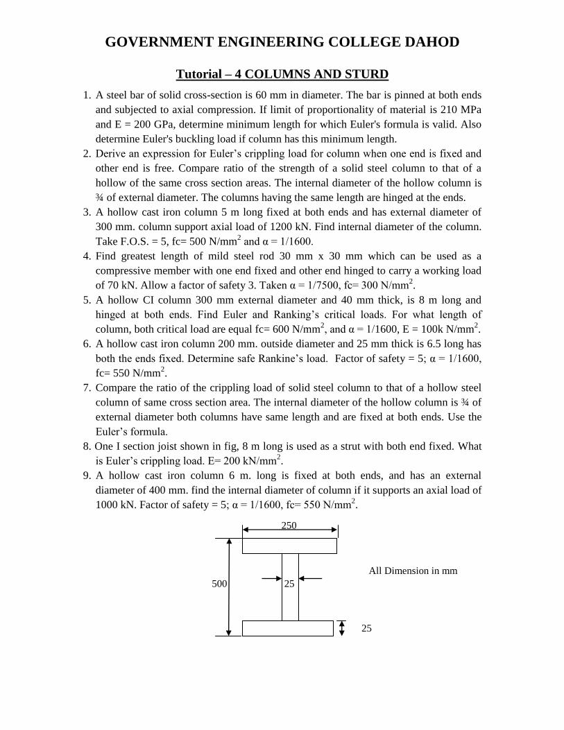
8. One I section joist shown in fig, 8 m long is used as a strut with both end fixed. What
is Euler‟s crippling load. E= 200 kN/mm2.
9. A hollow cast iron column 6 m. long is fixed at both ends, and has an external
diameter of 400 mm. find the internal diameter of column if it supports an axial load of