GOVERNMENT OF INDIA MINISTRY OF RAILWAYS Centre for Advanced Maintenance TECHnology Maharajpur, Gwalior - 474 005 (INDIA) : 0751 - 2470869 & Fax : 0751 - 2470841 LWR ON GIRDER BRIDGES CAMTECH/2011/C/LWR-GB/1.0 March – 2011 EXECELLENCE IN MAINTENANCE (For Official Use Only)
Transcript
GOVERNMENT OF INDIA MINISTRY OF RAILWAYS
Centre
for
Advanced
Maintenance
TECHnology
Maharajpur, Gwalior - 474 005 (INDIA)
: 0751 - 2470869 & Fax : 0751 - 2470841
LWR ON GIRDER BRIDGES
CAMTECH/2011/C/LWR-GB/1.0
March – 2011
EXECELLENCE IN MAINTENANCE
(For Official Use Only)
LWR ON GIRDER
BRIDGES
Foreword
To minimise the vibration on track raised by impact of
running wheel on fish plated rail joint, it is desirable to eliminate
fish plated joint by providing long welded rails on girder bridges.
This handbook is prepared by CAMTECH to elaborate the
track length which may be welded long rail on different span of
girder bridges in all four temperature zone of Indian Railways.
I hope that this handbook will be of significant help to
Civil Engineering personnel in Railways.
CAMTECH/Gwalior S. C. Singhal
Date: 17.03.2011 Executive Director
Preface
The track structure on Indian Railways has now been
modernised to a great extent. The old concept of Rail Joint being a
necessary evil no longer holds true. Rails are now being welded as long
continuous welded rails to provide joint-less track with smooth side. So
this book is required for provision of maximum overall length of
bridges permitted on long welded rails on girder bridges.
This handbook is prepared to meet the objective for provision
of long welded rails on girder bridges and to provide assistance to the
field staff involved in construction of track structure on girder bridges,
converting fish plated track in to LWR on girder bridges and
maintaining LWR on girder bridges. CAMTECH has taken utmost care
to include all necessary details and attention has been paid to include
maintenance/defects of small fittings used in channel sleepers to upkeep
of track tolerances with in good riding comfort, as now a days steel
channel sleepers are being used on girder bridges
This handbook does not supersede any existing instructions
from Railway Board, RDSO & Zonal Railways and the provisions of
IRPWM and LWR manual on the subject. This handbook is not
statutory and contents are only for the purpose of guidance. Most of the
data & information mentioned herein are available in some form or the
other in various books and other printed matter.
CAMTECH/Gwalior S. K.Saxena
Date: 16.03.2011 Dy. Director/Civil
CONTENTS
Sr.
No.
Description Page
Nos.
Forward i
Preface ii
Content iii
Correction Slip iv
1.0 Introduction 1
2.0 Long Welded Rails 1
3.0 Track structure on Girder Bridge 2
3.1 While converting existing fish plated track into
LWR, following precautions shall be taken
2
3.2 Miscellaneous 3
4.0 Bridge Timber 3
5.0 Steel Channel Sleepers 5
5.1 Steel Channel Sleeper in Track Circuited Zone 6
6.0 Maximum overall length of bridges permitted
on LWR on BG bridges without ballasted deck
8
7.0 Locations over which LWR/CWR not to be laid 15
8.0 Locations to be identified prior to completion
of work
16
Disclaimer 17
Notes 18
ISSUE OF CORRECTION SLIPS
The correction slips to be issued in future for this
handbook will be numbered as follows:
CAMTECH/2011/C/LWR-GB/1.0/CS. # XX date ……...........
Where “XX” is the serial number of the concerned
correction slip (starting from 01 onwards).
CORRECTION SLIPS ISSUED
Sr. No.
of
C.Slip
Date
of
issue
Page no. and
Item No.
modified
Remarks
CAMTECH/C/2011/LWR-GB/1.0
LWR on Girder Bridges March - 2011
1
Go to index
1.0 Introduction
The Indian Railways has now entered into the phase of introducing high speed trains for which extensive R&D on stability of track structures including girder bridges is supposed to be carried out in future. Presently, the practice for maintaining the track over girder bridges is exhaustive and needs improvements to accommodate the heavy traffic. Rails are now being welded as long continuous welded rails to provide joint-less track with smooth ride. In subsequent Paras, the necessary technical details including effective maintenance practices have been covered. And also the defects of small fittings used in channel sleepers to upkeep of track tolerances within good riding comfort have been given due consideration as now a days steel channel sleepers are being used on girder bridges. 2.0 Long Welded Rails
Long Welded Rails (LWR) is a welded rail, the central part of which does not undergo any longitudinal movement due to temperature variation. A length of greater than 250 m on Broad Gauge (BG) and 500 m on Metre Gauge (MG) will normally function as LWR. The maximum length of Long Welded Rails under Indian conditions shall normally be restricted to one block section.
CAMTECH/C/2011/LWR-GB/1.0
LWR on Girder Bridges March - 2011
2
Figure - Long Welded Rails 3.0 Track structure on Girder Bridge
Rails: Rails of following section shall be welded in to LWR/CWR.
Gauge Rail Section
B.G. 90R/52 kg/ 60 kg.
M.G. 75/90 R LWR already laid with 60 R rails on MG may be allowed to continue.
3.1 While converting existing fish plated track into
LWR, following precautions shall be taken (i) The rails shall be tested ultrasonically and all
defective rails replaced before conversion in to LWR. (ii) Rails ends which are bent, hogged, battered or
having history of bolt-hole cracks shall be cropped before welding for conversion in to the LWR.
CAMTECH/C/2011/LWR-GB/1.0
LWR on Girder Bridges March - 2011
3
Go to index
New rails, used in LWR shall, as far as possible be without fish-bolt holes. Joining of rail ends temporarily during installation on LWR shall be done by 1 metre long fish plates with special screw clamps/joggled fish plates having slotted grooves & bolted clamps, with speed restrictions.
3.2 Miscellaneous
(i) Wherever LWR is followed by fishplate track/SWR, the same track structure as that of LWR shall be continued for three rail length beyond SEJ.
(ii) In one LWR, two different rail sections are not
permitted.
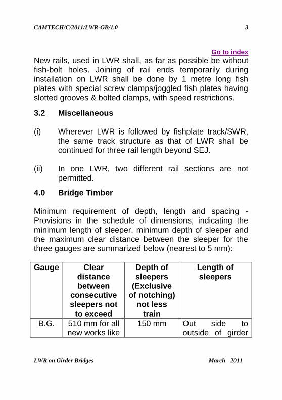
4.0 Bridge Timber Minimum requirement of depth, length and spacing - Provisions in the schedule of dimensions, indicating the minimum length of sleeper, minimum depth of sleeper and the maximum clear distance between the sleeper for the three gauges are summarized below (nearest to 5 mm):
Gauge Clear distance between
consecutive sleepers not
to exceed
Depth of sleepers
(Exclusive of notching)
not less train
Length of sleepers
B.G. 510 mm for all new works like
150 mm Out side to outside of girder
CAMTECH/C/2011/LWR-GB/1.0
LWR on Girder Bridges March - 2011
4
rebuilding, regirdering or
through sleeper
renewal this shall be kept as 450 mm
flanges plus 305 mm but not less than 2440 mm.
M.G. 305 mm 125 mm Out side to outside of girder flanges plus 305 mm but not less than 1675 mm.
N.G. 152 mm (for 610 mm
gauge) 254 mm (for 762 mm gauge)
125 mm Out side to outside of girder flanges plus 305 mm but not less than 1525 mm.
Note: The details are for timbers directly resting on longitudinal girder.
5.0 Steel Channel Sleepers Wooden sleepers are most ideal type of sleepers for bridges. But due to shortage of timber there is no other alternative accept steel channel sleepers. Most of the steel girder bridges have been provided with steel channel sleepers. Its proper inspection for assessing the performance and subsequently maintenance is required for its proper functioning.
CAMTECH/C/2011/LWR-GB/1.0
LWR on Girder Bridges March - 2011
5
Keyman will carry special spanner for tightening of nuts of hook bolts and clips. The inspecting officials will particularly ensure that the nuts are tight and they retain their tightness. The keyman shall check all fittings such as:
Hook bolts
Elastomeric Pads for its proper position.
Inner clip (tip with Tee bolt and tightness of nut along with its retention).
Outer clip (tip with Tee bolt and tightness of nut along with its retention).
Annular cap and single coil spring washer for missing, if any.
Rubber pads for its displacement form its proper position.
Split pin
CAMTECH/C/2011/LWR-GB/1.0
LWR on Girder Bridges March - 2011
6
Rubber pads provided between guard rail and channel sleeper.
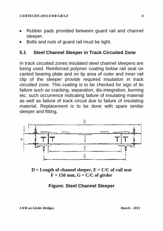
Bolts and nuts of guard rail must be tight. 5.1 Steel Channel Sleeper in Track Circuited Zone In track circuited zones insulated steel channel sleepers are being used. Reinforced polymer coating below rail seat on canted bearing plate and on lip area of outer and inner rail clip of the sleeper provide required insulation in track circuited zone. This coating is to be checked for sign of its failure such as cracking, separation, dis-integration, burning etc. such occurrence indicating failure of insulating material as well as failure of track circuit due to failure of insulating material. Replacement is to be done with spare similar sleeper and fitting.
D = Length of channel sleeper, E = C/C of rail seat
F = 150 mm, G = C/C of girder
Figure: Steel Channel Sleeper
CAMTECH/C/2011/LWR-GB/1.0
LWR on Girder Bridges March - 2011
7
A) Hook Bolts: The hook bolt should be of adequate size to provide the double coil spring washer in place of single coil spring washer. There should not be any gap between split pin and nut of the bolt. In case of any gap existing after tightening the bolt the gap should be filled by plain washers of suitable thickness for effectiveness of the split pin. Similar in MS clips inner and outer, the single coil spring washer shall be replaced with double coil spring washer. All hook bolts and Tee bolts shall be provided with split pins to eliminate the chances of falling down.
B) Elastomeric Pads: Its role to maintain the track
quality as well as transferring the load coming from track to sub-structure. Due to damaged/crushed/torn elastomeric pads, the cross level of the track gets disturbed during loaded condition.
C) Grooved Rubber Pads: Rubber pads should be
checked for any permanent set. Heavy vibration and frequent requirement for tightening of bolts will be indicative of permanent set in the rubber pads. Actual permanent set can be found out by actual measuring of the thickness of the rubber pads. In case of any permanent set the rubber pad should be replaced by the new one.
CAMTECH/C/2011/LWR-GB/1.0
LWR on Girder Bridges March - 2011
8
Go to index
6.0 Maximum overall length of bridges permitted on LWR on BG bridges without ballasted deck
(I) Bridges provided with rail free fastening (single span
not exceeding 30.5 metre and having slide bearing both ends)
Temperature zones
Rail section used
Rail free fastenings on bridges type of sleeper
used on approaches PRC/ST in Metre
I 60 KG 52 Kg./90 R
30 45
II 60 KG 52 Kg./90 R
11 27
III 60 KG 52 Kg./90 R
11 27
IV 60 KG 52 Kg./90 R
11 27
Over all length of the bridge should not exceed the maximum as above with following stipulations:
a) Rail free fastening shall be provided through out the length of the bridge between abutments.
b) The approach track up to 50 m on both sides shall be well anchored by providing any one of the following:
ST sleepers with elastic fastenings.
CAMTECH/C/2011/LWR-GB/1.0
LWR on Girder Bridges March - 2011
9
PRC sleepers with elastic rail clips with fair ‘T’ or similar type creep anchor.
c) The ballast section of approach track up to 50 metre
shall be heaped up the foot of the rail on the shoulders and kept in well compacted and consolidated condition during the months of extreme summer and winter.
(II) Bridges provided with rail free fastenings and partly
box-anchored (with single span not exceeding 30.5 metre and having sliding bearings at both ends)
Temperature zones
Rail section used
Rail free fastenings on bridges type of sleeper used on
approaches PRC/ST in Metre
I 60 KG 52 Kg./90 R
77 90
II 60 KG 52 Kg./90 R
42 58
III 60 KG 52 Kg./90 R
23 43
IV 60 KG 52 Kg./90 R
23 43
Overall length of the bridge should not exceed the maximum as above with following stipulations:
CAMTECH/C/2011/LWR-GB/1.0
LWR on Girder Bridges March - 2011
10
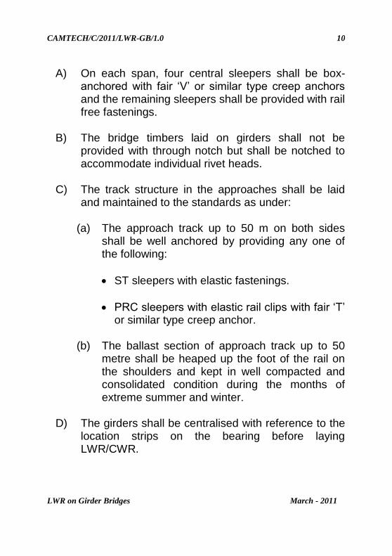
A) On each span, four central sleepers shall be box-anchored with fair ‘V’ or similar type creep anchors and the remaining sleepers shall be provided with rail free fastenings.
B) The bridge timbers laid on girders shall not be
provided with through notch but shall be notched to accommodate individual rivet heads.
C) The track structure in the approaches shall be laid
and maintained to the standards as under:
(a) The approach track up to 50 m on both sides shall be well anchored by providing any one of the following:
ST sleepers with elastic fastenings.
PRC sleepers with elastic rail clips with fair ‘T’ or similar type creep anchor.
(b) The ballast section of approach track up to 50
metre shall be heaped up the foot of the rail on the shoulders and kept in well compacted and consolidated condition during the months of extreme summer and winter.
D) The girders shall be centralised with reference to the
location strips on the bearing before laying LWR/CWR.
CAMTECH/C/2011/LWR-GB/1.0
LWR on Girder Bridges March - 2011
11
E) The sliding bearing shall be inspected during the months of March and October each year and cleared of all foreign materials. Lubrication of the bearing shall be done once in two years.
(III) Welded rails may be provided from piers to pier with
rail free fastenings and with SEJ on each pier. The rail shall be box-anchored on four sleepers at the fixed end of the girder if the girder is supported on rollers on one side and rockers on other side. In case of girder supported on sliding bearing on both sides, the central portion of the welded rails over each span shall be box-anchored on four sleepers.
CAMTECH/C/2011/LWR-GB/1.0
LWR on Girder Bridges March - 2011
12
Figure – Welded rail from pier to pier
(IV) LWR may also be continued over a bridge with the provision of SEJ at the far end approach of the girder bridge using rail-free fastenings over the girder bridge. The length of the bridge in this case, however, will be restricted by the capacity of the SEJ to absorb expansion, contraction & creep, if any of the rails. The length of the bridges with the above arrangements that can be permitted in various rails temperature zones for LWR/CWR with SEJs having maximum movement of 120 mm and 190 mm are as follows:
CAMTECH/C/2011/LWR-GB/1.0
LWR on Girder Bridges March - 2011
13
Go to index
Rail temperature
zone
Maximum movement
of SEJ used (mm)
Maximum length of bridge with SEJ in m
Initial gap to be provided at td in mm
With ST/PRC approach sleeper
With CST-9
approach sleeper
With ST/PRC approach sleeper
With CST-9
approach sleeper
IV 190 55 45 70 65
III 190 70 70 70 65
II 190 110 100 65 65
I 190 160 150 65 60
II 120 20 15 40 40
I 120 50 50 40 40
Note: In this case SEJ is to be installed 10 m away from the
abutments.
CAMTECH/C/2011/LWR-GB/1.0
LWR on Girder Bridges March - 2011
14
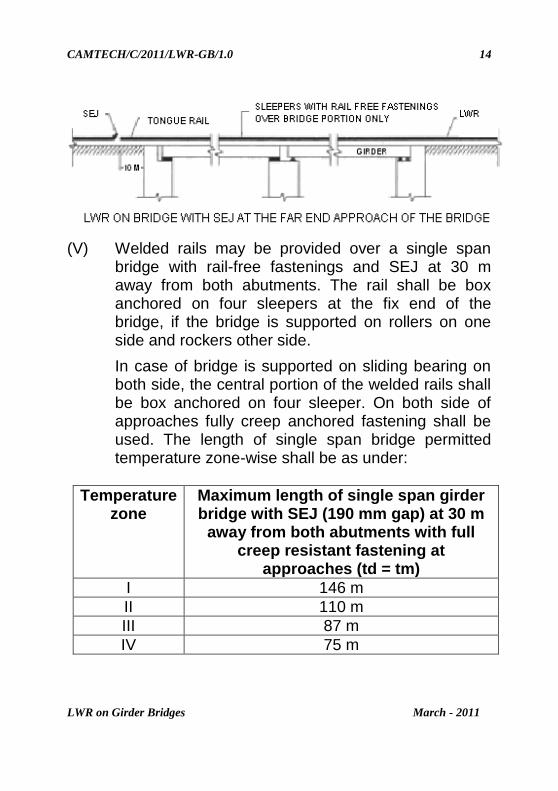
(V) Welded rails may be provided over a single span bridge with rail-free fastenings and SEJ at 30 m away from both abutments. The rail shall be box anchored on four sleepers at the fix end of the bridge, if the bridge is supported on rollers on one side and rockers other side.
In case of bridge is supported on sliding bearing on both side, the central portion of the welded rails shall be box anchored on four sleeper. On both side of approaches fully creep anchored fastening shall be used. The length of single span bridge permitted temperature zone-wise shall be as under:
Temperature zone
Maximum length of single span girder bridge with SEJ (190 mm gap) at 30 m
away from both abutments with full creep resistant fastening at
approaches (td = tm)
I 146 m
II 110 m
III 87 m
IV 75 m
CAMTECH/C/2011/LWR-GB/1.0
LWR on Girder Bridges March - 2011
15
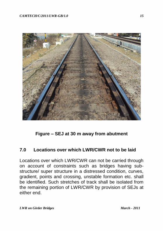
Figure – SEJ at 30 m away from abutment 7.0 Locations over which LWR/CWR not to be laid Locations over which LWR/CWR can not be carried through on account of constraints such as bridges having sub-structure/ super structure in a distressed condition, curves, gradient, points and crossing, unstable formation etc. shall be identified. Such stretches of track shall be isolated from the remaining portion of LWR/CWR by provision of SEJs at either end.
CAMTECH/C/2011/LWR-GB/1.0
LWR on Girder Bridges March - 2011
16
Go to index
8.0 Locations to be identified prior to completion of
work Location where following preliminary works are required to be carried out shall be identified for completion before laying of LWR/CWR:
(i) Replacement of insulated joints by glued joints. (ii) Stabilisation of trouble some formation. (iii) Rehabilitation of weak bridges involving removal or
lifting of rails or introduction of temporary arrangements.
LWR/CWR shall not be continued over bridges with overall length as specified above for BG and not more than 20 metre for MG.
Bridges on which LWR/CWR is not permitted/ provided shall be isolated by a minimum length of 36 metre well anchored track on either sides.
A detailed plan shall be made showing the exact position of Tongue/Stock Rails of SEJ.
***
CAMTECH/C/2011/LWR-GB/1.0
LWR on Girder Bridges March - 2011
17
Go to index
Disclaimer
The document prepared by CAMTECH is meant for the
dissemination of the knowledge/ information mentioned
herein to the field staff of Indian Railways. The contents of
this handbook/booklet are only for guidance and not
statutory. Most of the data & information contained herein
in the form of numerical values are indicative and based on
the tests/trials conducted by various agencies generally
believed to be reliable. While reasonable care and effort has
been taken to ensure that information given is at the time
believed to be fare and correct and opinion based thereupon
are reasonable. Due to very nature of research it can not be
represented that it is accurate or complete and it should not
be relied upon as such. The reader/user is supposed to refer
the relevant codes/ manuals available on the subject before
actual implementation in the field.
***
CAMTECH/C/2011/LWR-GB/1.0
LWR on Girder Bridges March - 2011
18
NOTES
1
2
3
4
5
6
7
8
9
10
11
12
13
14
***
CAMTECH/C/2011/LWR-GB/1.0
LWR on Girder Bridges March - 2011
19
OUR OBJECTIVE
The contents of this booklet are for guidance only & are not
statutory. It also does not supersede any existing instructions
from Railway Board, RDSO and zonal Railways & the provisions
of IRWM, BIS Codes/Reports on the subject.
If you have any suggestion & any specific comments, please write