R Job Name: Job Number: Model Numbers: Page SPECIFICATION SUBMITTAL gp-3 03.10.04 Power Equipment GP Dimming Panels GRAFIK Systems GP Dimming Panels 220-240 Volt (non-CE) GP3/4 Mini Panels GP8-24 Standard-Size Panels GP Dimming Panels provide power and dimming for up to 24 load circuits and control any light source, including full-conduction non-dim. Models available with: • 220-240V input power. • 3 to 24 circuits. • Different feed types and breakers. GP Dimming Panels work with: • GRAFIK Eye 4000 Control Units. • GRAFIK 5000TM, GRAFIK 6000®, and GRAFIK 7000® Systems. • LP Dimming Panels. • XP SoftswitchTM Panels. • DMX512 dimming systems via the 2LINKTM option.
Transcript
R
Job Name:
Job Number:
Model Numbers:
PageSPECIF ICATION SUBMITTAL
gp-3 03.10.04
Power EquipmentGP Dimming PanelsGRAFIK Systems
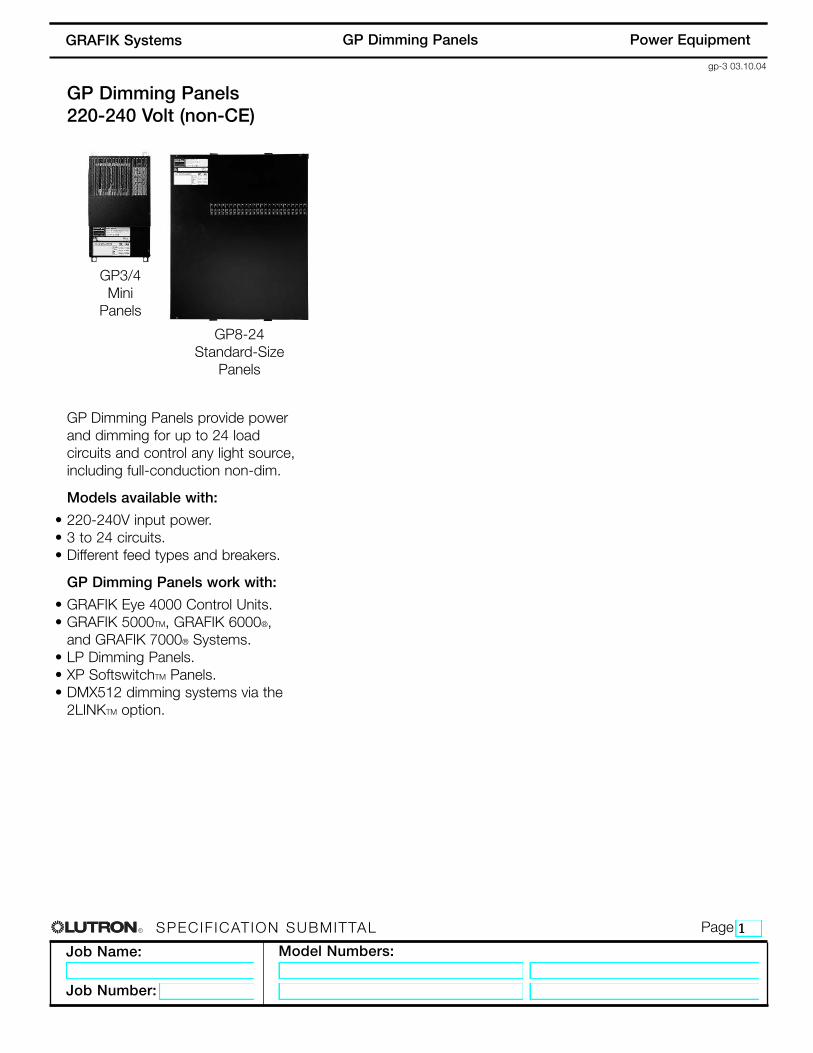
GP Dimming Panels220-240 Volt (non-CE)
GP3/4Mini
Panels
GP8-24 Standard-Size
Panels
GP Dimming Panels provide powerand dimming for up to 24 loadcircuits and control any light source,including full-conduction non-dim.
Models available with:
• 220-240V input power.• 3 to 24 circuits.• Different feed types and breakers.
GP Dimming Panels work with:
• GRAFIK Eye 4000 Control Units.• GRAFIK 5000TM, GRAFIK 6000®,
and GRAFIK 7000® Systems.• LP Dimming Panels.• XP SoftswitchTM Panels.• DMX512 dimming systems via the
2LINKTM option.
R
Job Name:
Job Number:
Model Numbers:
PageSPECIF ICATION SUBMITTAL
gp-6 03.10.04
Power EquipmentGP Dimming PanelsGRAFIK Systems
Wiring
• Internal: Prewired by Lutron.• System communications: Low-
voltage Class 2 (PELV) wiringconnects Dimming Panels toother components.
• Line (mains) voltage: Feed, load,and control circuit wiring only.No other wiring or assemblyrequired.
Filter Chokes
• Load current rise time ismeasured at a 90 degreeconduction angle, with 120Vinput power.
• 10-90% of load currentwaveform:- 350µSec rise time at 50%
• Lightning strike protection: MeetsANSI/IEEE standard 62.41-1980.Can withstand voltage surges of upto 6000V and current surges of upto 3000A.
• 10-year power failure memory: Automatically restores lighting toscene selected prior to powerinterruption.
Sources/Load Types
Operates these sources with asmooth continuous Square Lawdimming curve or on a fullconduction non-dim basis:
• Incandescent (Tungsten)/Halogen• Magnetic Low Voltage Transformer• Electronic Low Voltage Transformer1
• Lutron Electronic Fluorescent Dimming Ballasts
• Magnetic Fluorescent Lamp Ballasts• Optional modules allow for control of
0-10V, DSI, and PWM load types.• Operates HID sources on a full
conduction non-dim basis.
Dimming Cards
• Panel current ratings are listedfor continuous operation.
• RTISSTM filter circuit technologycompensates for incoming linevoltage variations: No visibleflicker with +/-2% change inRMS voltage/cycle and +/-2%Hz change in frequency/sec-ond.
• Arcless-relay air gap-offswitches (one per load circuit)ensure open load circuits whenoff function selected. Eliminatearcing at mechanical contactswhen loads are switched.
Physical Design
• Enclosure: NEMA-Type 1 (Type2 available upon request), IP-20protection; #16 U.S. GaugeSteel. Indoors only.
• Weight: 30-175 pounds(14-80kg).
• Mounting: Surface mount only.Allow space for ventilating.
Environment/Heat Dissipation
• Patented, ribbed aluminum heatsink base cools Panel byconvection. No fans.
• 32-104°F (0-40°C). Relativehumidity less than 90%non-condensing.
Specifications - 220-240 Volt
1 Reverse-phase control transformers require an ELVI PowerInterface. Check phase with transformer manufacturer.
R
Job Name:
Job Number:
Model Numbers:
PageSPECIF ICATION SUBMITTAL
gp-9 03.10.04
Power EquipmentGP Dimming PanelsGRAFIK Systems
Prefix:GP for GP Dimming Panel
Number of Load Circuits:Indicates number of load circuits in the panel
Voltage:240 for 220-240V
Feed Type:2 for 1 phase 2 wire4 for 3 phase 4 wire
Panel Feed:IS for Isolator Switch
Branch Circuit Breakers:16 for 16A branch circuit breakers10 for 10A branch circuit breakers
Region Suffix:AU for 220-240 V
Custom Panel Suffix:Indicates panel with special options
How to Build a GP Model Number
Prefix
Number ofLoad Circuits
Voltage
Feed Type
Panel Feed
Branch Circuit Breakers
Region Suffix
Custom Panel Suffix
G P 1 2 - 2 4 0 4 I S - 1 6 A U - C G P - _ _ _
R
Job Name:
Job Number:
Model Numbers:
PageSPECIF ICATION SUBMITTAL
gp-15 03.10.04
Power EquipmentGP Dimming PanelsGRAFIK Systems
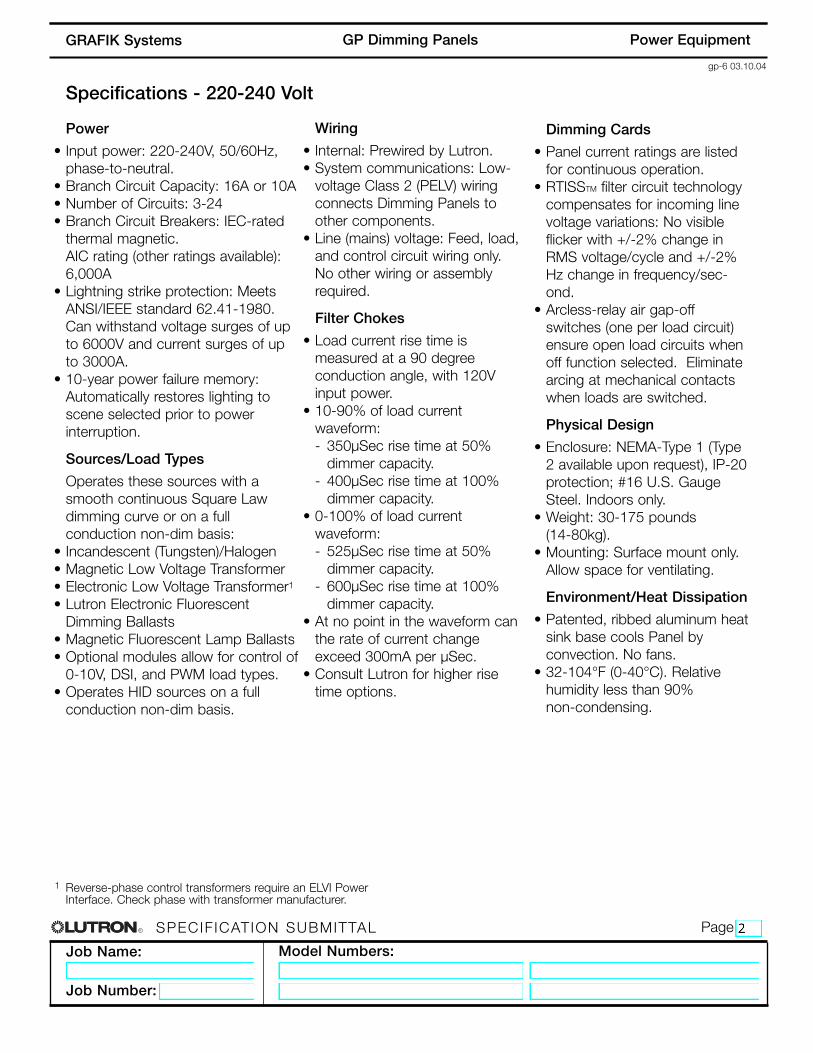
MaximumFeed
Number Of Circuits
FeedType
Panel Feed/ BranchCircuit Breakers
16A10A16A10A
16A1
10A1
48A30A16A10A
16A10A
1Ø, 2W
3Ø, 4W
FeedThrough
GP3
GP4
220-240V Power
GP3/4 Mini ModelsOnly standard panels listed. Consult Lutron for further options.
125A
125A
125A
125A
125A
125A
Isolator Switch
Isolator Switch
Isolator Switch
Isolator Switch
Isolator Switch
Isolator Switch
16A10A
16A10A16A10A16A10A16A10A16A10A
220-240V Power
1Ø, 2W
3Ø, 4W
3Ø, 4W
3Ø, 4W
3Ø, 4W
3Ø, 4W
GP8
GP12
GP16
GP20
GP24
MaximumFeed
Number Of Circuits
FeedType
BranchCircuit Breakers1
PanelFeed
GP8-24 Standard-Size ModelsOnly standard panels listed. Consult Lutron for further options.
1 Breakers located in distribution panel supplied by others.
R
Job Name:
Job Number:
Model Numbers:
PageSPECIF ICATION SUBMITTAL
gp-16 03.10.04
Power EquipmentGP Dimming PanelsGRAFIK Systems
Dimensions for GP3/4 Mini Panels
19 1/2"(495mm)
21 1/8"(537mm)
18"(457mm)
Top View
3 5/8”(92 mm) 6 1/4”
(160 mm)
9 5/8”(244 mm)
18”(457 mm)
19 1/2”(495 mm)
1 1/8”(29 mm)
2 3/4”(70 mm)
1 1/8”(29 mm)
1 3/16”(30 mm)
2 3/4”(70 mm)
5 1/4”(133 mm)
21 1/8”(537 mm)
11”(279 mm)
2 3/4”(70 mm)
1 1/2”(38 mm)
1 1/2”(38 mm)5 1/2”
(140 mm)
1 5/8”(41 mm)
5 1/8”(130 mm)
Left Side View Front View
Bottom View
Keyhole accepts a maximumof 1/4” (6mm) mounting bolt.#10 M6 recommended.
Load CircuitWiring Feed Wiring
Class 2 (PELV)Wiring
Right Side View
R
Job Name:
Job Number:
Model Numbers:
PageSPECIF ICATION SUBMITTAL
gp-17 03.10.04
Power EquipmentGP Dimming PanelsGRAFIK Systems
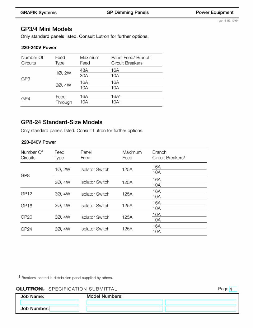
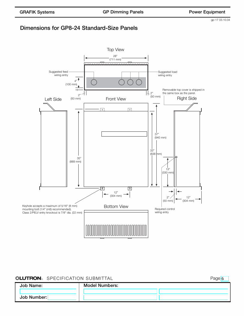
Dimensions for GP8-24 Standard-Size Panels
Top View
Front View Right SideLeft Side
Bottom ViewKeyhole accepts a maximum of 5/16" (8 mm)mounting bolt (1/4" (m8) recommended).Class 2/PELV entry knockout is 7/8" dia. (22 mm)
Suggested feedwiring entry
Removable top cover is shipped inthe same box as the panel.
Required controlwiring entry
Suggested loadwiring entry
28”(711 mm)
37”(940 mm)
35”(889 mm)
12”(304 mm) 12”
(304 mm)
13”(330 mm)
33”(838 mm)
2”(50 mm)
2”(50 mm)
2”(50 mm)
4”(100 mm)
R
Job Name:
Job Number:
Model Numbers:
PageSPECIF ICATION SUBMITTAL
gp-21 03.10.04
Power EquipmentGP Dimming PanelsGRAFIK Systems
• Surface mount indoors. • Panel generates heat. Mount only where ambient
temperature will be 0-40 °C (32-104 °F).• This equipment is air cooled. Do not block vents or
warranty will be void. Leave 12" (31cm) clearancesabove, below, and in front of Panel. No clearancenecessary on sides.
• Reinforce wall structure for weight and local codes.
Wiring Raceway
LoadCircuitWiring
FeedWiring
BranchCircuitBreakers
TerminalBlocksfor LoadCircuits
Class 2 (PELV)Wiring
12"(31cm)
minimum
12"(31cm)minimumtop andfront
Water damages Panels! Install Panels in a location where they will not get wet.
GP3/4 FrontView
GP3/4 SideView
For maximum Feed and Wire Sizes,consult Wiring Overview page.
• Dimming Panels will hum slightly and internal relayswill click while in operation. Mount where audiblenoise is acceptable.
• Mount Panels so line (mains) voltage wiring is at least6 feet (1.8m) from sound or electronic equipment andwiring.
• GP Panels must be mounted within 7° of truevertical.
GP3/4 Mini Panel Mounting
Panel
GP3/4
MaximumBTUs/Hour
685
Weight(without packaging)
30 lbs. (14kg)
R
Job Name:
Job Number:
Model Numbers:
PageSPECIF ICATION SUBMITTAL
gp-22 03.10.04
Power EquipmentGP Dimming PanelsGRAFIK Systems
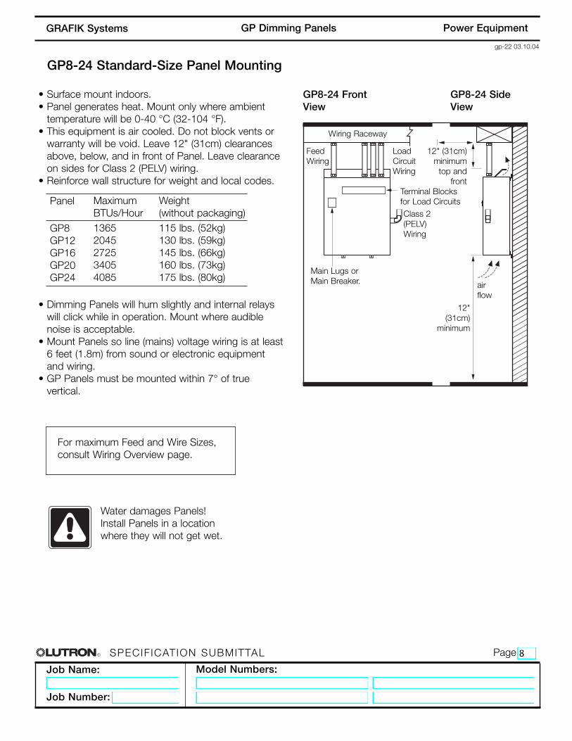
• Surface mount indoors. • Panel generates heat. Mount only where ambient
temperature will be 0-40 °C (32-104 °F).• This equipment is air cooled. Do not block vents or
warranty will be void. Leave 12" (31cm) clearancesabove, below, and in front of Panel. Leave clearanceon sides for Class 2 (PELV) wiring.
• Reinforce wall structure for weight and local codes.
Wiring Raceway
FeedWiring
airflow
LoadCircuitWiring
Main Lugs or Main Breaker.
Terminal Blocks for Load Circuits
12" (31cm)minimum
top and front
12"(31cm)
minimum
Water damages Panels! Install Panels in a location where they will not get wet.
GP8-24 FrontView
GP8-24 SideView
For maximum Feed and Wire Sizes,consult Wiring Overview page.
• Dimming Panels will hum slightly and internal relayswill click while in operation. Mount where audiblenoise is acceptable.
• Mount Panels so line (mains) voltage wiring is at least6 feet (1.8m) from sound or electronic equipmentand wiring.
• GP Panels must be mounted within 7° of truevertical.
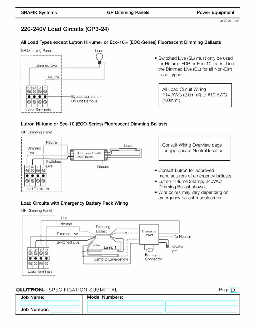
• Wire colors may vary depending onemergency ballast manufacturer.
220-240V Load Circuits (GP3-24)
DL1
R
Job Name:
Job Number:
Model Numbers:
PageSPECIF ICATION SUBMITTAL
gp-40 03.10.04
Power EquipmentGP Dimming PanelsGRAFIK Systems
Control UnitControl Interface
Dimming Panel
Wallstations
Control UnitControl Interface
Power Panel Link
Dimming PanelProcessor Panel
Wallstations
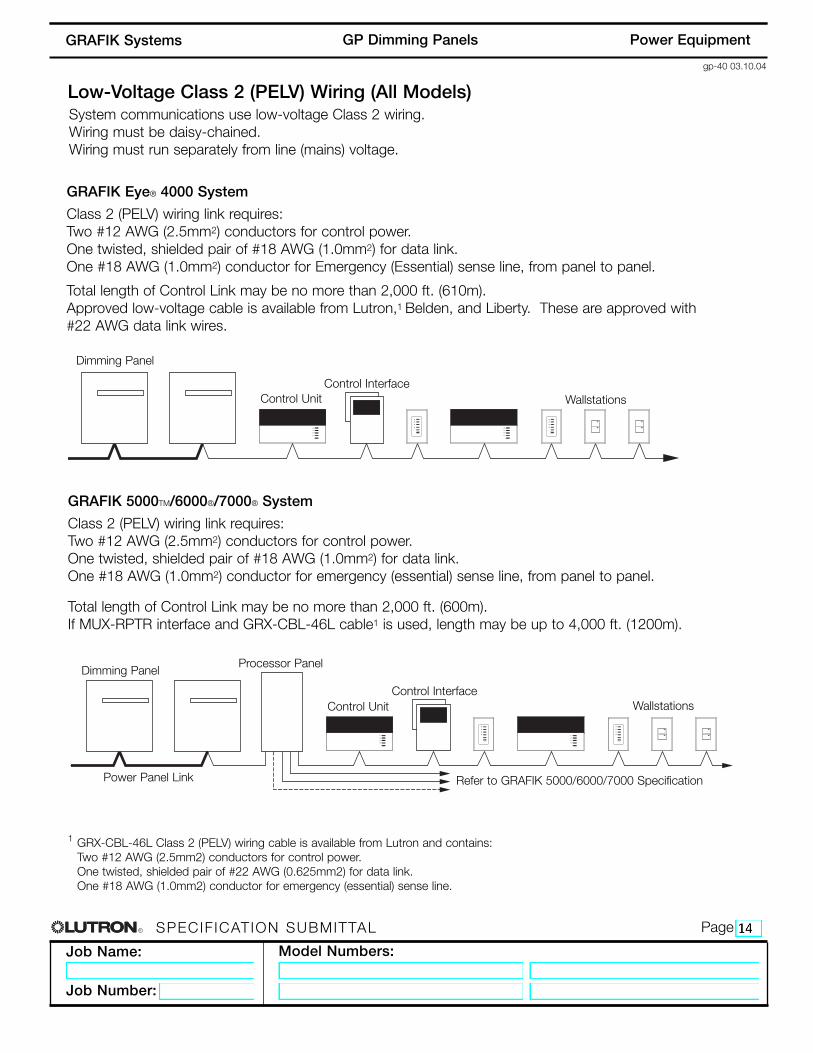
GRAFIK Eye® 4000 System
Class 2 (PELV) wiring link requires:Two #12 AWG (2.5mm2) conductors for control power.One twisted, shielded pair of #18 AWG (1.0mm2) for data link.One #18 AWG (1.0mm2) conductor for Emergency (Essential) sense line, from panel to panel.
Total length of Control Link may be no more than 2,000 ft. (610m).Approved low-voltage cable is available from Lutron,1 Belden, and Liberty. These are approved with#22 AWG data link wires.
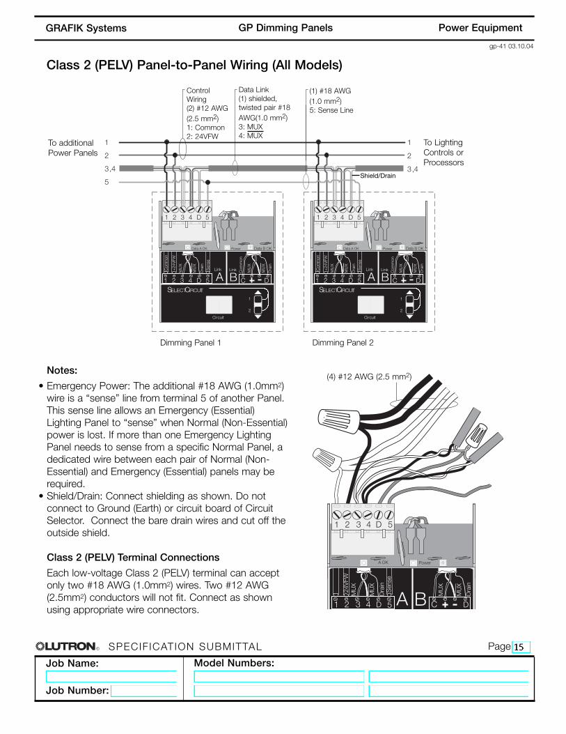
Low-Voltage Class 2 (PELV) Wiring (All Models)
GRAFIK 5000TM/6000®/7000® System
Class 2 (PELV) wiring link requires:Two #12 AWG (2.5mm2) conductors for control power.One twisted, shielded pair of #18 AWG (1.0mm2) for data link.One #18 AWG (1.0mm2) conductor for emergency (essential) sense line, from panel to panel.
Total length of Control Link may be no more than 2,000 ft. (600m).If MUX-RPTR interface and GRX-CBL-46L cable1 is used, length may be up to 4,000 ft. (1200m).
System communications use low-voltage Class 2 wiring. Wiring must be daisy-chained.Wiring must run separately from line (mains) voltage.
GRX-CBL-46L Class 2 (PELV) wiring cable is available from Lutron and contains:Two #12 AWG (2.5mm2) conductors for control power.One twisted, shielded pair of #22 AWG (0.625mm2) for data link.One #18 AWG (1.0mm2) conductor for emergency (essential) sense line.
Data Link(1) shielded, twisted pair #18AWG(1.0 mm2)3: MUX4: MUX
A OK Power
1 2 3 4 5D
24V
FWM
UX
MU
X
Dra
inS
ense
1 2 3 4 D 5 B Dra
in
MU
X
MU
X
C DA
(4) #12 AWG (2.5 mm2)Notes:
• Emergency Power: The additional #18 AWG (1.0mm2)wire is a “sense” line from terminal 5 of another Panel.This sense line allows an Emergency (Essential)Lighting Panel to “sense” when Normal (Non-Essential)power is lost. If more than one Emergency LightingPanel needs to sense from a specific Normal Panel, adedicated wire between each pair of Normal (Non-Essential) and Emergency (Essential) panels may berequired.
• Shield/Drain: Connect shielding as shown. Do notconnect to Ground (Earth) or circuit board of CircuitSelector. Connect the bare drain wires and cut off theoutside shield.
Class 2 (PELV) Terminal Connections
Each low-voltage Class 2 (PELV) terminal can acceptonly two #18 AWG (1.0mm2) wires. Two #12 AWG(2.5mm2) conductors will not fit. Connect as shownusing appropriate wire connectors.
R
Job Name:
Job Number:
Model Numbers:
PageSPECIF ICATION SUBMITTAL
gp-44 03.10.04
Power EquipmentGP Dimming PanelsGRAFIK Systems
Tridonic is a registered trademark of Zumtobel AG.
Option
CustomMainBreaker
Delta Power
BranchCircuitProtection
LutronTen VoltModule(TVM)
LockingCover
2LinkTM
Description
Panel features a custom main breaker size.
Panel accepts Delta power feed (phase to phase).Available for 240 V only. Limited to 10A, 2-pole circuits.
Branch Circuit Breakers with higher AIC ratings or specialbreaker types such as:• ELB (Earth Leakage Breaker - 230 V CE/240 V non-CE
Only).• RCD (Residual Current Device - 230 V CE/240 V non-CE
Only).
Allows panel to operate fluorescent ballasts that meetIEC 929 standards for 0-10V control including:• Lutron’s TVE ballasts• 0-10V neon• PWM fluorescent• Tridonic® DSI (Digital Serial Interface). The TVM can sink or source 5OmA (typically 25-50 ballasts)on each circuit.
Prevents accidental switching of circuit breakers. Adds anadditional 2.25”(57.2mm) to the front of panel. Available forGP8-GP24 only
• Allows a DMX512 theatrical console to operate the loadcircuits in the dimming panel.
• Allows a GRAFIK Eye 4000 System to handle 128 zones(two links of 64 zones).
• Allows two GRAFIK Eye 4000 Systems to share the samedimming panel.
Application
Jobs with special load requirements.
Areas with Delta power.
Jobs with fluorescent ballasts thatrequire 0-10V, PWM, or DSI control.
Service corridors and public areas.
• Control of architectural lightingfrom a DMX512 theatrical consoleis required.
• A mix of architectural andtheatrical lighting exists on the job.
• Multiple systems where space forpanels is limited.