GPIB Controllers USER’S MANUAL VER. 2.0C • SEP 2008 No part of this manual may be reproduced without permission GPIB USB USB 100kHz GPIB (IEEE-488.2) Controller Card, with GPIB Library Software ® CyberResearch ® , Inc. www.cyberresearch.com 25 Business Park Dr., Branford, CT 06405 USA 203-483-8815 (9am to 5pm EST) FAX: 203-483-9024
Transcript
GPIB Controllers
USER’S MANUAL VER. 2.0C • SEP 2008
No part of this manual may be reproduced without permission
GPIB USB USB 100kHz GPIB (IEEE-488.2)
Controller Card, with GPIB Library Software
®
CyberResearch®, Inc. www.cyberresearch.com
25 Business Park Dr., Branford, CT 06405 USA 203-483-8815 (9am to 5pm EST) FAX: 203-483-9024
September 3rd 2008 The information in this document is subject to change without prior notice in order to improve reliability, design, and function and does not represent a commitment on the part of CyberResearch, Inc. In no event will CyberResearch, Inc. be liable for direct, indirect, special, incidental, or consequential damages arising out of the use of or inability to use the product or documentation, even if advised of the possibility of such damages. This document contains proprietary information protected by copyright. All rights are reserved. No part of this manual may be reproduced by any mechanical, electronic, or other means in any form without prior written permission of CyberResearch, Inc.
Trademarks “CyberResearch,” and “GPIB USB,” are trademarks of CyberResearch, Inc. Other product names mentioned herein are used for identification purposes only and may be trademarks and/or registered trademarks of their respective companies.
• NOTICE • CyberResearch, Inc. does not authorize any CyberResearch product for use in life support systems, medical equipment, and/or medical devices without the written approval of the President of CyberResearch, Inc. Life support devices and systems are devices or systems which are intended for surgical implantation into the body, or to support or sustain life and whose failure to perform can be reasonably expected to result in injury. Other medical equipment includes devices used for monitoring, data acquisition, modification, or notification purposes in relation to life support, life sustaining, or vital statistic recording. CyberResearch products are not designed with the components required, are not subject to the testing required, and are not submitted to the certification required to ensure a level of reliability appropriate for the treatment and diagnosis of humans.
iv
GPIB USB
Revision # Description Date of Issue 1.1 Initial Release July 2007
2.0C Revision September 3rd 2008
Getting Started Compatibility, Shipment Verifi cation, Software License, Installation, CYR
Explorer, Controller Confi guration, Communicate and GPIB Keyboard Controller Program, Testing the Card and Utility Programs.
General Information Controller Card Descriptions, Driver Software Capabili t ies,
Supported Languages and Application Programs, Physical Specifi cations, and Accessories.
488.2V3 Driver Driver Description, Software Components, Usage, Command Set Description,
Programming Notes, Program Examples, Troubleshooting, Use with Test and Measurement Programs, and Converting Existing Programs.
NI 488.2/NI 488 Command References Command Conventions, Command Lists, Parameters, Constants, and Error
Lists, and Command Defi nitions
Appendix A1 IEEE 488.1 Bus Description, IEEE 488.2 Standard, 488.2 Status
Structure, Protocols, Common Commands and SCPI Commands.
Contents
2
4
A
3
1
5
v
This page intentionally left blank
vi
1-1
1
1
Getting Started1.1 INTRODUCTION
This manual provides information and directions for using the CyberRe-search IEEE-488.2V3 GPIB Controller product. This manual applies to the GPIB USB module.
This Getting Started Section covers shipment verifi cation, product com-patibility, software license, installation, troubleshooting and the use of CyberResearch's interactive Explorer and GPIB Keyboard Controller pro-grams and other utilities. The instructions for GPIB AnyWhere™ are in a separate document.
CyberResearch's 488.2V3 Driver is a multi controller capable driver that can control up to 16 CyberResearch GPIB Controllers on Windows 2K, XP and Vista32 operating systems. The 488.2V3 Driver supports programs written with Microsoft C, Visual Basic and Visual Basic.NET (2005).
1.2 COMPATIBILITY WITH OTHER SOFTWARE
CyberResearch's 488.2V3 Driver provides a GPIB-32.DLL that is compat-ible with National Instruments 488 'ib' and 488.2 command sets. In most cases, CyberResearch's 488.2V3 Driver can be used to run programs written for the National Instruments 488.2 Driver without being recompiled. CyberResearch's 488.2V3 Driver is compatible with VISA libraries from Agilent and National Instruments and can be used to run LabVIEW and LabWindow/CVI, VEE, MATLAB, TestPoint and other programs that make VISA calls.
CyberResearch does not provide support for .NET programs produced by earlier versions of Visual Studio such as Visual Studio 2002 or Visual Studio 2003. Upgrade to Visual Studio 2005 before running any GPIB programs.
1-2
1
1.3 SHIPMENT VERIFICATION
If you ordered the GPIB USB Module we should have sent you:
(1) Model GPIB USB IEEE-488.2 Interface Module (1) USB Cable (1) Support CD-ROM (1) IEEE-488.2 Bus Controllers User’s Manual
Figure 1-3 GPIB USB Controller Module
The 488.2V3 Driver installation programs are on the Support CD-ROM disk. If anything is missing or damaged, save the shipping carton and contact CyberResearch, Inc. immediately. You can also download a currentinstallation program from CyberResearch's website.
1.4 SOFTWARE LICENSE AGREEMENT
Note - Please carefully read this License agreement prior to opening the media envelope or using the software. By opening the media envelope and/or using the software, the customer agrees to all provisions of this license. If you do not agree with the license, you may return this product for a full refund.
1.4.1 License
In exchange for payment of this invoice, CyberResearch grants the customer a license to the software subject to the following conditions.
1-3
1
Customer may not reverse engineer or reverse-compile the software. Customer agrees the software is copyrighted and may only make archival copies of it. Customer shall not sublicense or distribute copies of the soft-ware without the written permission of CyberResearch. A transfer or sale of the software to a third party is permitted, if the third party agrees to this license and the original purchaser ceases use of the software.
Customer may use CyberResearch's software to make executable programs and distribute them freely without permission of CyberResearch.
CyberResearch may terminate this license and seek damages if the cus-tomer fails to comply with the license after being notifi ed in writing to cure the failure. Customer agrees that the software does not include updates and CyberResearch is not responsible for any damage to the customer's computer or other equipment.
1.5 BE SURE YOU HAVE THE CORRECT SOFTWARE
If you are installing the 488.2V3 drivers on a PC with Windows 2K, XP, or Vista 32 then you can use the CYR_488.2V3_Install program dated January 2007 or later on the supplied CD-ROM. Install the 488.2V3 Driver only in Windows 2K, Windows XP and Vista 32-bit operating systems. Note the following Windows limitations:
Windows operating systems require the following upgrades: For Windows 2K, Service Pack 4 For Windows XP, Service Pack 2 For Vista (32-bit)
CyberResearch's new Explorer utility program requires Microsoft's .NET Framework 2.0 or later to run. The CYR_488.2V3_Install program tests for the .NET Framework and will indicate if it needs to be installed. Windows 2K and XP users who do not have Microsoft's Visual Studio 2005 or .NET Framework 2.0 installed on the PC can:
1. Install the free express version of Visual Studio 2005 by download-ing it from Microsoft's website:
While we try to ship the most up-to-date software with our products, we sometimes have to make changes to the software to fi x problems or to add other features. We recommend that you check CyberResearch's website before installing your software to be sure that you have the latest version of the 488.2V3 Driver.
Periodically check CyberResearch's website for GPIB driver updates. The software fi le on the website is changed when we update the driver.
If you are using our GPIB Controllers with third party application packages, review the appropriate paragraph in Section 4 of this manual for special instructions.
1.6 INSTALLATION
Perform the steps in this section to install CyberResearch's 488.2V3 Driv-ers and GPIB Controller hardware in a Intel type PC running Windows 2K, XP or Windows Vista 32 operating systems. Install the software before installing the hardware.
1.6.1 Software Installation Procedures
The following steps will install the 488.2V3 Driver and its support fi les for your GPIB Controller in the default Installation Directory (\Program Files\CyberResearch\GPIB 488.2V3\ folder). We recommend that you do not change the default Installation Directory. If you do change the installation directory, verify the installation by clicking the Verify Installation button in the CYR Explorer's main window.
1.6.1.1 Windows Preparation
Review paragraph 1.5 to be sure you operating system is up to date.
1.6.1.2 488.2V3 Driver Installation
1. Close all other applications before installing the software. If you have any GPIB Services running they should be stopped. If a GPIB service
1-5
1
is running, the existing GPIB-32.DLL cannot be overwritten.2. If another GPIB Controller Card was previously installed in the com-
puter, uninstall it. Find and delete all GPIB-32.DLL and GPIB.INI fi les in the computer.
3. Be sure you are logged in as an Administrator.4. Insert the Support CD-ROM in the computer's CD ROM drive. The
CD-ROM will autorun and bring up the selection screen.5. Click on the "Install 488.2V3 Driver" button and follow the instructions
on the next screen to run the CYR_488_2V3_Install program.6. Follow the instructions on the screen to select your language. 7. If the Installer indicates you need the .NET Framework, you can install
it from the Support CD 8. Go to paragraph 1.6.2 to install your GPIB Controller card or mod-
ule.
1.6.2 Hardware Installation Procedure s
1.6.2.3 GPIB USB Installation
To install a GPIB USB do the following:1. Reboot if directed by the installation program.2. Plug the GPIB USB USB-to-GPIB Controller into an empty powered
USB socket. Do not use the USB port on a keyboard or on a bus powered hub. The computer will take a few seconds to fi nd the unit and down load its fi rmware. It will do this two times for each USB Controller that is connected to the computer.
3. Observe that the GPIB USB go through their selftest routine and end with a blinking RDY LED.
4. Go to paragraph 1.6.3 to complete the installation.
1.6.3. Installation Confi rmation
Confi rm the installation process by checking the GPIB heading in the Device Manager to verify that the hardware and driver were installed. Steps 1 and 2 may vary with different Windows operating systems.
1. Right click My Computer. Select Properties. 2. Click the Device Manager button in the middle of the System Proper-
ties Window.3. For LPCI or PXI cards, locate the Adlink heading. 4. For USB devices, locate the CYR_USB_Devices heading. 5. Verify that the new hardware is listed and that there is not a yellow '!'
in front of the hardware's name. See paragraph 1.6.5 for Installation Troubleshooting suggestions.
1-6
1
1.6.4 Confi guration and Finish
You must confi gure your GPIB Controller before they can be used to control GPIB devices. If you have .NET Framework installed, you can run CYR's Explorer program which will automatically confi gure your controllers. See paragraph 1.6.4.1. If you do not have .NET Framework, use the CYR Confi gure program to manually confi gure your GPIB Controllers. See paragraph 1.6.4.3.
1.6.4.1 CYR Explorer and Confi gure Program
1. Go to C:\Program Files\CyberResearch\GPIB 488.2V3\Utilities folder, and run CYR Explorer
2. CYR Explorer will test the driver installation status when it starts. Follow the instructions given if Explorer fi nds any installation faults.
3. Explorer will generate the initial Confi guration File with default values listed in Table 1-1 for all of the installed CyberResearchGPIB Control-lers.
4. Finally Explorer will search for and display all GPIB Controllers and the devices connected to them as a tree structure in the Confi guration Tree window.
5. To change a GPIB Controller's confi guration, highlight the GPIB Controller's name (GPIBn) in the tree view. The Board type is dis-played in the Device properties window. Click the Confi gure button to launch the Confi gure program. Make any necessary changes to the Controllers' confi guration and use the Apply button to save the changes. If you have multiple GPIB Controllers, use the Confi gure window to associate the correct virtual controller name (GPIBn) with a specifi c GPIB Controller card or module. See paragraph 1.7.2 for detailed Confi gure directions.
6. CyberResearch's Explorer can be used to communicate with any GPIB Device. Highlight the GPIB Device or its Controller in the tree structure. Click the Communicate with Instrument button to launch the Communicate program. See paragraph 1.8 for detailed instruc-tions for running the Communicate program.
1.6.4.2 Installation Test
1-7
1
While the Explorer performs a check of the software installation when it starts, the user may want to perform a more detailed check of the installation.
1. From C:\Program Files\CyberResearch\GPIB 488.2V3\Utilities folder, and run CYR Explorer.
2. Click the Verify Installation button to launch the Verify routine.3. Click Test to run the Installation Test. The Verify routine will warn you
if you have located the GPIB-32.DLL in a non-standard location. While GPIB programs will run with the GPIB-32.DLL in alternate locations, they may fail if another user has a different path or if a program is run from another directory.
1.6.4.3 CYR Confi gure Program
If you did not run Explorer, you need to run CYR Confi gure Program to confi gure your GPIB Controllers before you can use them. If you did run Explorer, skip this step.
1. From C:\Program Files\CyberResearch\GPIB 488.2V3\Utilities folder, and run the CYR Confi gure Program.
2. CYR Confi gure tests the installation and when it starts. If this is the fi rst time, only the Add Controller button will be enabled.
3. Click the Add Controller button to bring up the Add Controller Win-dow.
4. Select the type of GPIB Controller you are installing and click the Find button. The program will search for and list all GPIB Controllers of the selected type with their serial numbers or slot identifi cation number.
5. Select a Controller by its serial/id number and press the Add Control-ler button. The Controller will be added to the Confi guration File and displayed on the main Confi gure Form.
5. Make any necessary changes to the Controllers' confi guration and use the Apply button to save the changes. If you have multiple GPIB Controllers, use the Add Controller window to add each Controller to the Confi guration File. See paragraph 1.7.2 for detailed Confi gure directions.
1.6.5 INSTALLATION TROUBLESHOOTING
If you get an immediate Windows Exception Error when trying to run Explorer, the Access.DLL is missing. Uninstall and re-install the 488.2V3 Driver.
Most driver problems can be traced to a missing or extra GPIB-32.DLL. This could have been caused by a NI or Agilent GPIB service running during the installation or to residual software from an earlier GPIB card
1-8
1
installation. Stop all GPIB services, uninstall CyberResearch's driver and remove all GPIB-32.DLLs and GPIB.INI fi les from your system. Re-install CyberResearch's 488.2V3 Driver.
If you switch GPIB USB Controllers or cards, you need to run Explorer to add them to the GPIB.INI fi le. You can view the GPIB.INI fi le by highlight-ing My Computer in Explorer's Confi guration Tree window. If you want to recreate the GPIB.INI fi le, close all GPIB applications, unplug all GPIB USB Controllers and delete the GPIB.INI fi le. It is located in ..\Program Files\CyberResearch\Utilities folder. Then plug the USB Controllers back into the computer, wait for then to be enumerated and then run Explorer. Refresh the tree view until all controllers have been discovered.
If you have multiple controllers, you need to associate the correct physi-cal GPIB Controller with the virtual controller name (GPIBn) so that it can be found by your application program. Use Explorer's Confi gure form to change the GPIBn settings. See paragraph 1.7.2.
GPIB USB problems are usually traced to a non-updated operating sys-tem or an obsolete BIOS, a USB bus power problem, a faulty USB cable, or USB bus sleeping. Rarely is it a defective USB module. Do not plug the GPIB USB into a keyboard or mouse port or to a bus powered hub. Laptops should be set to keep the USB ports on at all times. Be sure you are using a USB 2.0 rated USB cable. If Verify indicates a GPIB USB fail-ure, disconnect it from the USB bus for 5 seconds and reconnect it. When the computer re-enumerates it, all of its LEDs should come on and then sequentially turn off. The RDY LED will blink if the unit passes its selftest. Else you will see a stuck pattern or multiple blinking LEDs. Try a different USB port, a different USB cable or use a powered hub. Check the USB module by installing it on a good desktop PC.
PCI card problems are usually a poorly seated card or one in a bad PCI slot. Be sure your PCI card is close to the processor and not in the end PCI slot..
If you are still having problems, contact CyberResearch's Support desk for help.
1.7 CYR EXPLORER PROGRAM
Explorer is a 488.2V3 utility program that combines test, confi gure and communicate functions in a simple, easy-to-use program. Explorer must be run whenever you add a new GPIB Controller to the system to update the Confi guration File. You do not have to run Explorer if you are simply unplugging and later re-plugging the same USB module(s) into your com-puter or powering the computer off and back on.
1-9
1
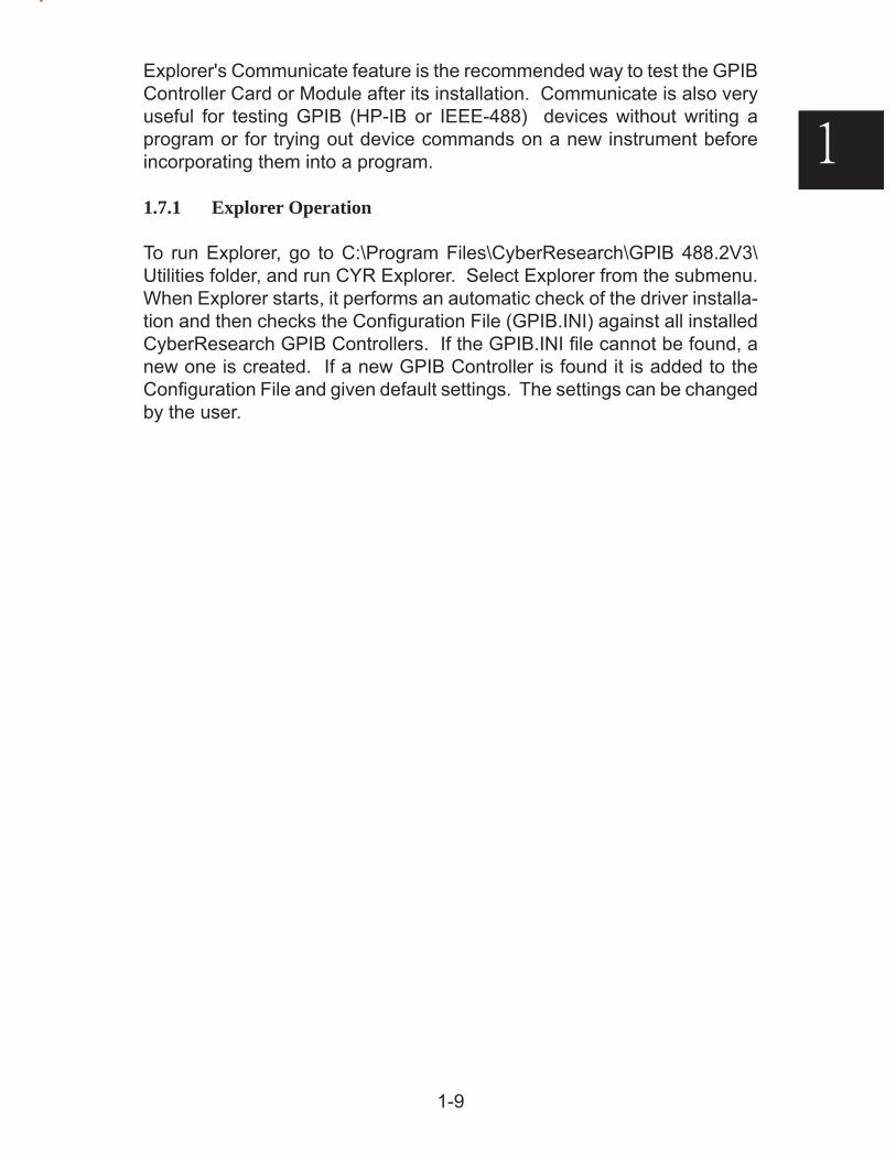
Explorer's Communicate feature is the recommended way to test the GPIB Controller Card or Module after its installation. Communicate is also very useful for testing GPIB (HP-IB or IEEE-488) devices without writing a program or for trying out device commands on a new instrument before incorporating them into a program.
1.7.1 Explorer Operation
To run Explorer, go to C:\Program Files\CyberResearch\GPIB 488.2V3\Utilities folder, and run CYR Explorer. Select Explorer from the submenu. When Explorer starts, it performs an automatic check of the driver installa-tion and then checks the Confi guration File (GPIB.INI) against all installed CyberResearch GPIB Controllers. If the GPIB.INI fi le cannot be found, a new one is created. If a new GPIB Controller is found it is added to the Confi guration File and given default settings. The settings can be changed by the user.
1-10
1
Figure 1-5 Explorer Main Window
All found Controllers and devices are shown in a tree structure in the left hand Confi guration Tree window. Device identifying properties are shown in the right hand Device Properties window by highlighting the desired device.
Highlighting a Controller's virtual name (GPIBn) enables the Communicate and Confi gure buttons. Clicking the Communicate button opens a GPIB keyboard like form that lets a user communicate with any device and send it numerous GPIB commands. See paragraph 1.8 for instructions on us-ing the Communicate form. Clicking Close returns the user to the Explorer window.
1.7.2 Confi guring your Controller
Clicking Confi gure opens the Controller Properties Window shown in Figure 1-6. The Controller Properties Window displays the Controller type in the title and its identifying serial number or slot location above the Interface Name. The user can change any of the Controller parameters in the Controller Properties Window by selecting them from pulldown boxes, by checking/unchecking boxes or by fi lling in values. Any device parameters that need setting or controller confi guration changes can be set by ibconfi g commands from your application program.
The default values fi lled in by Explorer will work with most IEEE-488.2/GPIB devices. The typical user will not have to change the settings for most ap-plications. However, multiple Controller users should set each Controller to its correct Interface Name so the application programs can fi nd it. Table
1-11
1
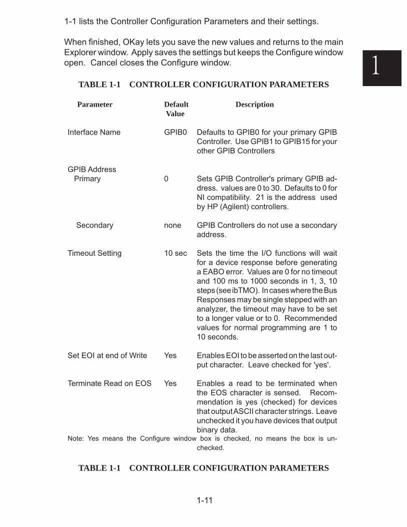
1-1 lists the Controller Confi guration Parameters and their settings.
When fi nished, OKay lets you save the new values and returns to the main Explorer window. Apply saves the settings but keeps the Confi gure window open. Cancel closes the Confi gure window.
TABLE 1-1 CONTROLLER CONFIGURATION PARAMETERS
Parameter Default Description Value
Interface Name GPIB0 Defaults to GPIB0 for your primary GPIB Controller. Use GPIB1 to GPIB15 for your other GPIB Controllers
dress. values are 0 to 30. Defaults to 0 for NI compatibility. 21 is the address used by HP (Agilent) controllers.
Secondary none GPIB Controllers do not use a secondary address.
Timeout Setting 10 sec Sets the time the I/O functions will wait for a device response before generating a EABO error. Values are 0 for no timeout and 100 ms to 1000 seconds in 1, 3, 10 steps (see ibTMO). In cases where the Bus Responses may be single stepped with an analyzer, the timeout may have to be set to a longer value or to 0. Recommended values for normal programming are 1 to 10 seconds.
Set EOI at end of Write Yes Enables EOI to be asserted on the last out-put character. Leave checked for 'yes'.
Terminate Read on EOS Yes Enables a read to be terminated when the EOS character is sensed. Recom-mendation is yes (checked) for devices that output ASCII character strings. Leave unchecked it you have devices that output binary data.
Note: Yes means the Confi gure window box is checked, no means the box is un-checked.
TABLE 1-1 CONTROLLER CONFIGURATION PARAMETERS
1-12
1
Parameter Default Description Value
Send EOI with EOS on Write Yes Asserts the EOI line when the EOS character is transmitted. A 'yes' setting requires that the EOS byte box must be fi lled in.
EOS byte 10 A decimal value, 0 to 127, that sets the character the library will add to the output string as a terminating character. A value of 0 means the library will only use the EOI line. The normal default is 10 which complies with the IEEE-488.2 Standard by adding a linefeed character to the output string.
8 Bit Compare on EOS No Yes selects 8-bit compare, No selects 7-bit compare for greater device compatibility. Only works if a non zero value is entered in the EOS box.
Figure 1-6 Confi guration Window
1-13
1
System Controller Yes Enables the Controller to be the System Controller. Leave checked for Cyber-Research Controllers. CyberResearch Controllers cannot be devices or passed control.
Assert REN when SC Yes Enables automatic assertion of the REN line when System Controller. Leave set to 'yes' for most programs.
Enable Auto Serial Poll No Enables background serial polls. Leave set to no (unchecked) unless running an application that requires Auto Serial Poll-ing. Note that many LabView applications require Auto Serial Polling.
Bus Timing 500 ns Sets the T1 handshaking time. Default is 500 ns which is the IEEE-488 value. Only reduce the timing value to 350 ns if your system has less than 10 meters of cable and you need a high (1 Mbyte per second) transfer rate. Values are 350 ns, 500 ns and 2 μsec.
Parallel Poll Time 2 μsec Selects the Parallel Poll wait for response time. The default is 2 μsec. If you are using Bus Extenders, check the Bus Extender manual for the manufacturer's recommended setting.
1.8 COMMUNICATE AND GPIB KEYBOARD PROGRAM
Explorer's Communicate and GPIB Keyboard Program are very similar pro-grams with few differences. Communicate is launched from Explorer and prefi lled with the target device's GPIB address and the Controller's virtual Interface Name. GPIB Keyboard is run as a standalone program and has the ability to select the Controller's Interface Name.
Both programs let a user interactively control GPIB devices directly from the computer's keyboard. They are the recommended way to test the GPIB Controller Card(s) or Module(s) after its installation. They are also very useful for testing GPIB (HP-IB or IEEE-488) devices without writing a program or for trying out device commands on a new instrument before incorporating them into a program.
The following description is written for the GPIB Keyboard program but it applies to Communicate except for where noted
1-14
1
System Controller Yes Enables the Controller to be the System Controller. Leave checked for Cyber-Research Controllers. CyberResearch Controllers cannot be devices or passed control.
Assert REN when SC Yes Enables automatic assertion of the REN line when System Controller. Leave set to 'yes' for most programs.
Enable Auto Serial Poll No Enables background serial polls. Leave set to no (unchecked) unless running an application that requires Auto Serial Poll-ing. Note that many LabView applications require Auto Serial Polling.
Bus Timing 500 ns Sets the T1 handshaking time. Default is 500 ns which is the IEEE-488 value. Only reduce the timing value to 350 ns if your system has less than 10 meters of cable and you need a high (1 Mbyte per second) transfer rate. Values are 350 ns, 500 ns and 2 μsec.
Parallel Poll Time 2 μsec Selects the Parallel Poll wait for response time. The default is 2 μsec. If you are using Bus Extenders, check the Bus Extender manual for the manufacturer's recommended setting.
1.8 COMMUNICATE AND GPIB KEYBOARD PROGRAM
Explorer's Communicate and GPIB Keyboard Program are very similar pro-grams with few differences. Communicate is launched from Explorer and prefi lled with the target device's GPIB address and the Controller's virtual Interface Name. GPIB Keyboard is run as a standalone program and has the ability to select the Controller's Interface Name.
Both programs let a user interactively control GPIB devices directly from the computer's keyboard. They are the recommended way to test the GPIB Controller Card(s) or Module(s) after its installation. They are also very useful for testing GPIB (HP-IB or IEEE-488) devices without writing a program or for trying out device commands on a new instrument before incorporating them into a program.
The following description is written for the GPIB Keyboard program but it applies to Communicate except for where noted
1-15
1
1.8.1 Program Operation
To run the GPIB Keyboard program, go to Start>Programs>CyberResearch>GPIB 488.2V3>CYR GPIB Keyboard Utility. Select GPIBkybd from the submenu. To run Communicate, highlight a GPIB Controller Name in the Explorer Tree Window and click the 'Communicate with Instrument' button.
When the GPIB Keyboard launches it defaults to using GPIB0 as its Con-troller Interface Name. To select a different Controller, highlight a deferent Interface Name from the pulldown box. Communicate uses the Interface Name passed to it when it was launched.
When the GPIB Keyboard starts it performs the 488.2 FindLstn command to learn what devices are connected to the GPIB bus and displays the found device addresses in the Device Response message box. If more than one device was found, enter the address for the desired device in the Device Address box and click the Set Address button. The GPIB Keyboard pro-gram uses the ppss address convention where the primary GPIB addresses (pp) are 0 to 30 and primary-secondary addresses (ppss) are 100 to 3030. Leading zeros are ignored. If no devices are found, the GPIB Keyboard program displays the 'No devices found' message.
Both programs default to an address of 0 for the GPIB controller card or module. The Controller's address can be changed by entering a new value into the Controller Address box and clicking Set Address. You only need to change the Controller address if it confl icts with a device address. Note: Sometimes device addresses get accidentally set to zero. If you have trouble communicating with devices or cannot fi nd a GPIB device, try setting the Controller to another address and run Findlstn. If a device is at address 0, set it to another address.
The programs enable the user to send or execute the most popular 488.1 and 488.2 functions by clicking the buttons in the right side panels and to send and receive device commands without writing a program or entering GPIB commands. Once the device address has been set, clicking on any 488.1 or 488.2 Command button will cause that command to be executed and sent to the selected device. The 488.1 buttons generate IFCs, Device Clear, Serial Poll the device and send the Trigger command. The 488.2 buttons perform the FindLstn protocol, the AllSerialPoll and the FindRQS protocols. Any device response appears in the Device Response message box. All controls have context help messages which popup as the cursor scans over a control.
To send data or a command to a device, simply type the device command string in the Device Command box and click Send. Click the Read Device
1-16
1
Figure 1-7 GPIB Keyboard Program
2-1
2
2
General Information2.1 INTRODUCTION
This section provides general information and specifi cations for CyberResearch's IEEE-488.2 GPIB Controller products and CyberResearch's 488.2V3 Driver for .NET programs.
2.2 MODEL GPIB USB CONTROLLER MODULE
The GPIB USB Controller Module provides the GPIB physical interface, both electrical and mechanical, for USB bus systems with an Intel type processor. The GPIB USB module is a high-speed, USB 1.1 device and is compatible with all powered USB 1.1 and 2.0 ports. The GPIB USB is Windows Plug&Play compli-ant for easy installation in systems with Microsoft Windows 2K, XP or Vista32 operating systems. The GPIB USB Module operates with the CyberResearch's 488.2V3 Driver to control GPIB devices.
Figure 2-2 GPIB USB Controller Module
2-2
2
2.3 488.2V3 DRIVER SOFTWARE CAPABILITIES
CyberResearch's 488.2V3 Driver provides the functional portion of the GPIB interface with two industry standard GPIB language libraries for C/C++, C#, Visual Basic and Visual Basic.NET. The language libraries are fully compatible with the National Instruments 488.2 Command set and National Instruments 488 (ib) Command set. `2.3.1 488.2V3 Driver Features
The 488.2V3 Driver software has the following features:
• All required IEEE-488.2 controller protocols and functions for Microsoft Visual C/C++ from Visual Studio 6 and Microsoft Visual Basic.NET (ver-sion 8) from Microsoft Visual Studio 2005.
• Supports National Instruments' VISA, LabView and LabWindows/CVI, Agilent's VISA and VEE, CEC Testpoint, MATLAB and Transera's HT Basic. Check CyberResearch's website for an updated list of supported applications.
• Interactive Explorer and Keyboard Controller Program for controlling GPIB devices and sending or receiving data without having to write a program.
• Visual C, Visual Basic 6 and Visual Basic.NET (2005) example programs and include fi les for each language.
• Automatic initialization of default values at power on.
• Multiple GPIB Buses - Any mix of the included GPIB Controllers up to 16 GPIB Controllers.
2.3.2 Supported Languages The 488.2V3 Driver supports: Microsoft Visual Basic for Windows (Ver 6.0) Microsoft Visual Basic.NET (2005) Microsoft C/C++ (Ver 6.0 and 2005) 2.3.3 Compatible Application Programs
The GPIB Controllers and 488.2V3 Drivers are compatible with the following
2-3
2
application programs: Agilent Benchlink™ Agilent IntuiLink Agilent IO Libraries Agilent VEE™ (versions 6 and later) CEC TestPoint (using NI or Agilent VISA) GPIB AnyWhere™ Matlab Mathworks Measurement Computing (ComputerBoards) SoftWire National Instruments' LabView™ (versions 5.1 and later) National Instruments' LabWindows/CVI National Instruments' VISA Driver (versions 2.1 and later)
2.3.4 Supported Command Sets
The 488.2 Drivers provide the following command sets:
National Instruments - 488.2 Commands National Instruments - 488.1 Commands VISA Commands when used with Agilent or National Instruments VISA library. PC2 Command Set - 488.1 and 488.2 Commands when used with the PC2W support fi les. 2.3.5 Controller Functions
As an IEEE 488.2 Bus controller, the GPIB Controllers perform AH1 and SH1 handshakes plus controller subsets C1 through C4, and C9 depending upon the
2-4
2
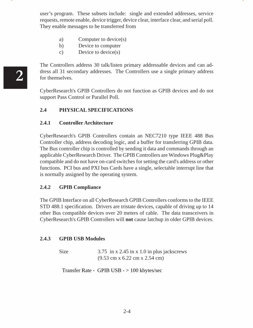
user’s program. These subsets include: single and extended addresses, service requests, remote enable, device trigger, device clear, interface clear, and serial poll. They enable messages to be transferred from
a) Computer to device(s) b) Device to computer c) Device to device(s)
The Controllers address 30 talk/listen primary addressable devices and can ad-dress all 31 secondary addresses. The Controllers use a single primary address for themselves.
CyberResearch's GPIB Controllers do not function as GPIB devices and do not support Pass Control or Parallel Poll.
2.4 PHYSICAL SPECIFICATIONS
2.4.1 Controller Architecture
CyberResearch's GPIB Controllers contain an NEC7210 type IEEE 488 Bus Controller chip, address decoding logic, and a buffer for transferring GPIB data. The Bus controller chip is controlled by sending it data and commands through an applicable CyberResearch Driver. The GPIB Controllers are Windows Plug&Play compatible and do not have on-card switches for setting the card's address or other functions. PCI bus and PXI bus Cards have a single, selectable interrupt line that is normally assigned by the operating system.
2.4.2 GPIB Compliance
The GPIB Interface on all CyberResearch GPIB Controllers conforms to the IEEE STD 488.1 specifi cation. Drivers are tristate devices, capable of driving up to 14 other Bus compatible devices over 20 meters of cable. The data transceivers in CyberResearch's GPIB Controllers will not cause latchup in older GPIB devices.
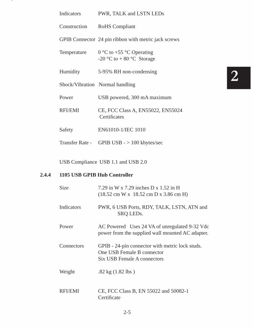
2.4.3 GPIB USB Modules
Size 3.75 in x 2.45 in x 1.0 in plus jackscrews (9.53 cm x 6.22 cm x 2.54 cm)
Transfer Rate - GPIB USB - > 100 kbytes/sec
2-5
2
Indicators PWR, TALK and LSTN LEDs
Construction RoHS Compliant
GPIB Connector 24 pin ribbon with metric jack screws
Temperature 0 °C to +55 °C Operating -20 °C to + 80 °C Storage
Humidity 5-95% RH non-condensing
Shock/Vibration Normal handling
Power USB powered, 300 mA maximum
RFI/EMI CE, FCC Class A, EN55022, EN55024 Certifi cates
Safety EN61010-1/IEC 1010
Transfer Rate - GPIB USB - > 100 kbytes/sec
USB Compliance USB 1.1 and USB 2.0
2.4.4 1105 USB GPIB Hub Controller
Size 7.29 in W x 7.29 inches D x 1.52 in H (18.52 cm W x 18.52 cm D x 3.86 cm H)
Indicators PWR, 6 USB Ports, RDY, TALK, LSTN, ATN and SRQ LEDs.
Power AC Powered Uses 24 VA of unregulated 9-32 Vdc power from the sup plied wall mount ed AC adapter.
Connectors GPIB - 24-pin con nec tor with metric lock studs. One USB Female B connector Six USB Female A connectors
Weight .82 kg (1.82 lbs )
RFI/EMI CE, FCC Class B, EN 55022 and 50082-1 Certifi cate
2-6
2
2.4.5 Approvals
Meets limits for Part 15, Class B of US FCC Docket 20780 and complies with EEC Standards EN 55022 and 50082-1.
3-1
3
3
488.2V3 Driver3.1 INTRODUCTION
This section describes CyberResearch's 488.2V3 Driver's support for C and Visual Basic applications that make NI compatible 488 (ib) or 488.2 Calls. This section includes the Software Organization, Command Set characteristics and Command Set Quick Reference lists.
3.2 488.2V3 DRIVER WIN32 COMPONENTS
CyberResearch's 488.2V3 Driver provides a GPIB-32.DLL that is command compatible with National Instruments' 488.1 (ib) or 488.2 Command Sets and VISA libraries from Agilent and National Instruments. Libraries are provided that support calls to the GPIB-32.DLL from 32-bit programs writ-ten in Microsoft Visual Studio 6 C/C++, Microsoft Visual Studio 6 Visual Basic and Microsoft Visual Studio 2005 Visual Basic .NET. The following paragraphs describe the Driver's software components. Figure 3-1 shows how they interact to control the GPIB hardware.
3.2.1 488.2V3 System Components
1. GPIB-32.DLL A 32-bit DLL that implements the NI 'ib' and 488.2 command sets.
2. USB488.SYS & USB device drivers that are loaded when the system recognizes the
USB488a.SYS 488-USB module or 1105.
3. USB4882.SYS & USB device drivers that are loaded when the system recognizes the
USB4882a.SYS 488-USB2 module. 3.2.2 C/C++ Support (Microsoft Visual Studio 6)
1. ICSdecl.h A header fi le with declarations for all C/C++ programs using the NI 488.2 Command Set.
3-2
3
2. GPIB-32.LIB A library fi le with functions for accessing the GPIB-32.DLL for 32-bit C/C++ applications.
3.2.3 Visual Basic Support (Microsoft Visual Studio 6)
1. GPIB-32.BAS A 32-bit Visual Basic fi le with program constants and Command Set declarations for linking to the NI 488.2 Command Set. Needs to be included with any Visual Basic program.
2. ICSVB.BAS A 32-bit Visual Basic fi le with constants and utility routines for the NI 488.2 Command Set. Needs to be included with any Visual Basic program.
3.2.4 Visual Basic.NET Support
1. GPIB-32.VB A 32-bit Visual Basic .NET fi le with program constants and Com-mand Set declarations for linking to the NI 488.2 Command Set.
2. ICSVB.VB A 32-bit Visual Basic .NET fi le with constants and utility routines for the NI 488.2 Command Set.
3.2.5 Utilities
1. Explorer.exe An Interactive Control Utility that lets a user fi nd, manage and confi gure up to 16 GPIB Controllers. Includes an interactive con-trol utility that communicates directly with GPIB devices without having to write a program.
1. GPIBkybd.exe An Interactive Control Utility that lets a user communicate directly with GPIB devices without having to write a program.
3. ICS_spy.exe A Utility program that lists the calls to the GPIB-32.DLL and the
returned responses and status information.
4. NI_Support A USB utility that adds Board type for compatibility with National Instruments' VISA.
5. Access.DLL A DLL that implements CyberResearch utility functions for CYR Explorer.
3.2.6 488-PC2 Components
The following components are included for compatibility with CyberResearch's older PC2 Command Set.
1. PC2W32.DLL A 32-bit DLL that implements the 488-PC2 Command Set.
4. PC2W.H A header fi le with 488-PC2 declarations for all C/C++ programs.
5. PC2W32.LIB A library fi le with functions for accessing the PC2W32.DLL
3-3
3
3. PC2W32.BAS - A 32-bit VB fi le with program constants and Command Set dec-larations for linking to the 488-PC2 Command Set.
4. Global4.BAS - A VB fi le with program variables for the 488-PC2 Command Set.
3.3 DRIVER USAGE
CyberResearch's 488.2V3 Driver provides two ways for users to control GPIB devices as shown in Figure 3-1. Visual Basic and C/C++/C# Application Programs can make 'ib' and 488.2 calls to CyberResearch' GPIB-32.DLL. CyberResearch's GPIB-32.DLL is compatible with National Instruments 488.2 Commands and the National Instruments 488 'ib' type Commands. Alter-natively, the user may install a GPIB-32.DLL compatible VISA library from Agilent or National Instruments and use a graphical program like LabView or write his Application Program using VISA calls.
VISA Library
G P I B - 3 2 . D L L
CYR DriversSystem Drivers
Physical GPIB Controllers
LabView, VEE or othergraphical program
C/C++, VB6, VBC NET application program
C/C++, VB6, VBC NETapplication program
Note: Gray boxes are part of CyberResearch's 488.2V3 Driver
Figure 3-1 488.2V3 Program Model
3-4
3
Notes: * Not supported by 488.2V3 Driver
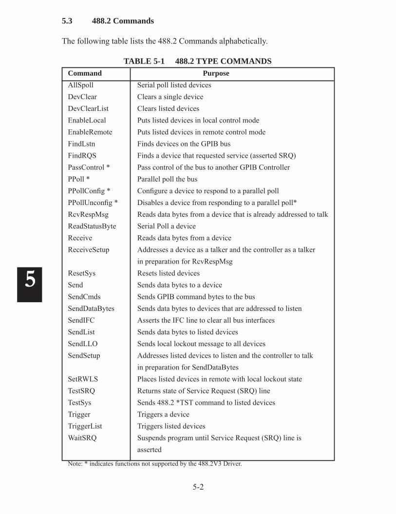
3.4 488.2V3 COMMAND SET
Table 3-1 provides a list of the 488.2V3 Driver's 488.2 Commands and their functions. Table 3-1 should only be used as a quick reference guide. Refer to the Command Reference Section for a complete description of each com-mand, its required parameters, parameter types, and examples.
The 488.2 Command Set is IEEE-488.2 compliant and includes the IEEE-488.2 Controller Protocol Commands like FindLstn.
TABLE 3-1 488.2 DRIVER COMMANDS
MNEMONIC DESCRIPTION
AllSpoll Serial Polls all devices DevClear Clears a single device
DevClearList Clears multiple devices
EnableLocal Enables local programming of a device
EnableRemote Enables remote programming of a device FindLstn Find devices on the bus that listen. FindRQS Find the device requesting service.
PassControl * Pass control to another controller.
PPoll * Parallel poll the bus.
PPollConfi g * Confi gure a device for parallel polling. PPollUnconfi g * Unconfi gure a device
RcvRespMsg Read data from a previously addressed device
ReadStatusByte Serial poll a single device. Receive Read data from a GPIB device.
ReceiveSetup Address a GPIB device as a talker and the GPIB Controller Card as a listener.
3-5
3
ResetSys Initialize a GPIB system.
Send Send data to one device. (ATN off) SendCmds Send GPIB commands (ATN on)
SendDataBytes Send data to a previously addressed device.
SendIFC Assert IFC to clear all GPIB interfaces.
SendList Send data to multiple devices.
Send LLO Send Local Lockout to all devices.
SendSetup Prepare devices to receive data.
SetRWLS Put devices in Remote with Lockout state.
TestSRQ Determine status of SRQ line.
TestSys Force devices to conduct self test. Trigger Trigger a single device.
TriggerList Trigger multiple devices.
WaitSRQ Wait until a device asserts the SRQ line.
TABLE 3-1 488.2 DRIVER COMMANDS (CONT'D)
MNEMONIC DESCRIPTION
3-6
3
3.5 488 COMMAND SET (IB COMMAND SET)
Table 3-2 provides a list of the 488.2V3 Driver's 488 (ib) Commands and their functions. Table 3-2 should only be used as a quick reference guide. Refer to the Command Reference Section for a complete description of each command, its required parameters, parameter types, and examples.
The 488 or 'ib' Command Set is composed of Device I/O routines for com-municating with the GPIB Device and lower lever Board I/O routines which require a more detailed knowledge of the GPIB bus and its operation for their successful use. The 488 Commands can be used in the following ways:
1. As a call i.e. Call ibrd(..)
2. As an il function i.e. err% = ilrd(.. ) if err% and EERR then...
3. As an ib function i.e. err% = ibrd(..) if err% and EERR then...
TABLE 3-2 488 DRIVER COMMANDS
MNEMONIC DESCRIPTION
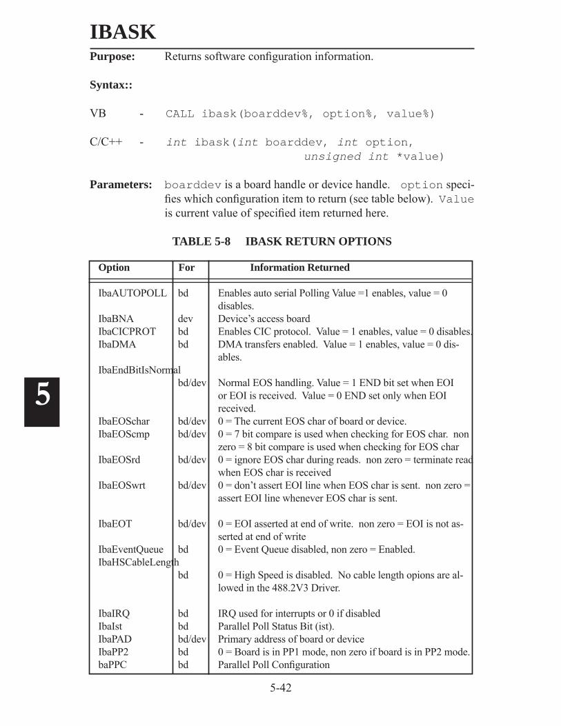
ibask Returns software confi guration information
ibbna Change access board of device
ibcac Become Active Controller
ibclr Clear specifi ed device
ibcmd Send GPIB commands from a string
ibcmda Send GPIB commands asynchronously from a string
ibconfi g Confi gure the driver
ibdev Open and initialize a device when the device name is un-known
ibdma Enable/Disable DMA
ibeos Change EOS
ibeot Change EOI
ibfi nd Open a device and return its unit descriptor
ibgts Go from Active Controller to standby
3-7
3
ibist Defi ne IST bit
iblines Return status of GPIB bus lines
ibln Check for presence of device on bus ibloc Got to Local (This is a device level command only)
ibnotify Notifi es user of one or more GPIB events by invoking a user callback routine. (488-USB C function only)
ibonl Place device online/offl ine
ibpad Change Primary address
ibpct * Pass Control
ibppc * Parallel Poll Confi gure
ibrd Read data to a string
ibrda Read data asynchronously
ibrdf Read data to fi le
ibrdi Read data from a device using an integer buffer
ibrdia Read integer data asynchronously from a device into an integer buffer
ibrpp * Conduct parallel poll
ibrsc * Request/release system control
ibrsp Return serial poll byte
ibrsv * Change system response.
ibsad Defi ne secondary address ibsic Send IFC
ibsre Set/clear REN line
ibstop Stop asynchronous I/O operation
TABLE 3-2 488 DRIVER COMMANDS (CONT'D)
MNEMONIC DESCRIPTION
Notes: * Not supported by 488.2V3 Driver
3-8
3
TABLE 3-2 488 DRIVER COMMANDS (CONT'D)
MNEMONIC DESCRIPTION
ibtmo Defi ne time limit
ibtrg Trigger selected device
ibwait Wait for event
ibwrt Write data from a string
ibwrta Write data asynchronously from a string
ibwrtf Write data from the fi le
ibwrti Write data to a device from an integer buffer
ibwrtia Write data asynchronously from an integer buffer
4-1
4
4
GPIB Programming 4.1 INTRODUCTION
This section describes how to use CyberResearch's 488.2V3 Driver to generate Visual Basic 6, Visual Basic.Net (2005) and C Language programs and its use with other Application Programs to control GPIB devices
4.2 GPIB PROGRAMMING TECHNIQUES
This section describes some basic GPIB programming concepts and is intended as a guide for anyone doing GPIB programming. All users should read the initialization section. A new GPIB user should read the description of the GPIB bus operation in Appendix A1 before proceeding. The concepts described below are general in nature. Refer to the selected Command Set Reference for the exact parameter defi nitions. See Section 4.6 for Troubleshooting ideas.
Note that the variable names used in the command examples are placeholders and can be changed to make them more descriptive for your program. Outstring$ can become CmdStr$, DVMSetup$ etc. Similarly, InString$ can become Rdg$, Oven-Temp$ etc. What is important in calling a command is the order of the variables and their defi nitions.
4.2.1 Program Outline
A typical GPIB program has the following steps:1. Initialize the GPIB Controller Card and the bus.2. Verify that the device(s) is (are) present.3. Setup the test by sending setup commands to the signal generators, measuring instruments and other devices.4. Read data or response(s) from the instruments(s).5. Release the devices and end the program
Steps 3 and 4 are repeated as needed to conduct the test
Most GPIB programs only use six to eight of the 25 or more commands in either command set. Once you have mastered these few commands, you can make pro-
4-2
4
grams of any degree of complexity and seldom need another command.
In some cases, it may be necessary to check a device's status to see if it has com-pleted a task or has data ready before reading data from a device. It may also be necessary to send a device some special GPIB bus commands to put it in a particular mode. These actions are also covered in the following paragraphs.
Figure 4-1 A Small GPIB Test System
4.2.2 Device Addressing
The GPIB bus has 32 addresses from 0 to 31. All GPIB devices are addressed with a unique primary address between 0 to 30. Address 31 is the Untalk or Unlisten address and is not used as a device address. The GPIB Controller card uses a pri-mary address to make itself a talker or a listener. HP/Agilent Controllers default to address 21; CyberResearch, National Instruments (NI) and NI Compatible controllers default to address 0. Therefore primary addresses 0 and 21 should not be used for GPIB device addresses.
Some devices use secondary addresses to address a channel or subfunction in the device or as an escape to a setup mode. An example is CyberResearch's Quad Serial Interface which uses secondary addresses to select a serial channel. There are 31 possible secondary addresses, 0 to 30. Again, secondary address 31 is not used by a device. GPIB Controllers do not use secondary addresses so there are no restricted secondary addresses.
The Windows operating system can support multiple GPIB Controller Cards depend-ing upon the card driver. CyberResearch's 488.2V3 Driver supports up to 16 GPIB Controllers. The GPIB Controller Card address is the CardID or Bd depending upon the Command Set used. The Driver uses a virtual name to refer to each GPIB Controller. The name is GPIBn where n varies from 0 (GPIB0) to 15.
The 488.2 Commands use two variables to express the board or device address. Bd is the Card number and starts with 0 for the fi rst card. Addr is a 16 bit vari-able with the secondary address in the upper byte and the primary address in the
No address is used when a command applies to all of the devices on the bus. A NOADDR constant has been predefi ned to simplify the programming. An ex-ample is
DevClear(Bd%, Addr) 'sends the SDC command to the specifi ed device.DevClear(Bd%, NOADDR) 'sends the Clear command to all devices on the bus.
One method of declaring addresses in a program is to list the device addresses at the beginning of the program.
M91% = 04 '4891 addressDVM% = 02 'DVM address
The 'ib' type Commands use two variables to express the board or device address. pad is the primary address variable. sad is the secondary address variable. These two addresses are used to create a board handle, referred to in this manual as 'bud', or a device handle, referred to as 'ud'. The handles are used by all subsequent ib commands to address the board or device. The board and device handles are returned by executing a ibdev command. CyberResearch uses bud% and ud% for board and device handles to make it easier to understand the commands use.
The GPIB Controller is initialized to be sure that it is the System Controller and Controller-in-charge of the bus. The bus is initialized to be sure that all of the devices are in a non-addressed state after their power turn-on. This is done by hav-ing the GPIB Controller issue an Interface Clear command (IFC pulse) and assert the REN line. It is also a good idea to check or set the bus timeout. Timeout is the amount of time that the program will wait for a device to respond to a com-mand before declaring an error and proceeding with the program. The following examples are in Visual Basic.
In the 488.2 Command Set, initialization is done with the following commands:Call SendIFC(Bd%) 'sends IFC and asserts ATNCall ibsre(Bd%, 1) 'sets REN onCall ibtmo(Bd%, T3s) 'sets Timeout to 3 seconds
SendIFC is a 488.2 command that sends IFC, asserts ATN and makes the board the Controller-in-Charge (CIC). Once a 488.2 command is executed, Bd can be used in place of the board handle (bud) in any subsequent ib type commands. ibsre and ibtmo are used to set REN and the timeout value because there are no equivalent 488.2 commands. T3s is a predefi ned timeout constant for 3 seconds. Do not use a timeout of 0 (or TNONE) except when debugging hardware by single stepping a command with a Bus Analyzer. ib type commands can be included in a 488.2 program when there is no equivalent 488.2 function.
'ib' Command Set users can replace Call SendIFC(Bd%) with:
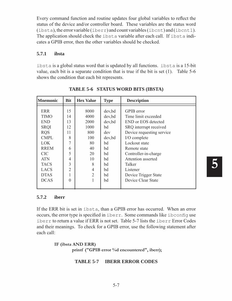
Both command sets return status in ibsta and errors in global variable iberr. ibsta should be checked after every command to be sure the ERR bit (EERR) is not set. You can use the gpiberr routine in icsvb.vb to create error messages as follows:
If (ibsta AND EERR) then Call gpiberr ("SendIFC Error") txtError.Text = RetMsg$ txtError.Visible = trueElse
You can also write commands as a function so each command returns the error value. i.e.
ioerr% =ibrd(Bd%, M91%, Instring$)
4-5
4
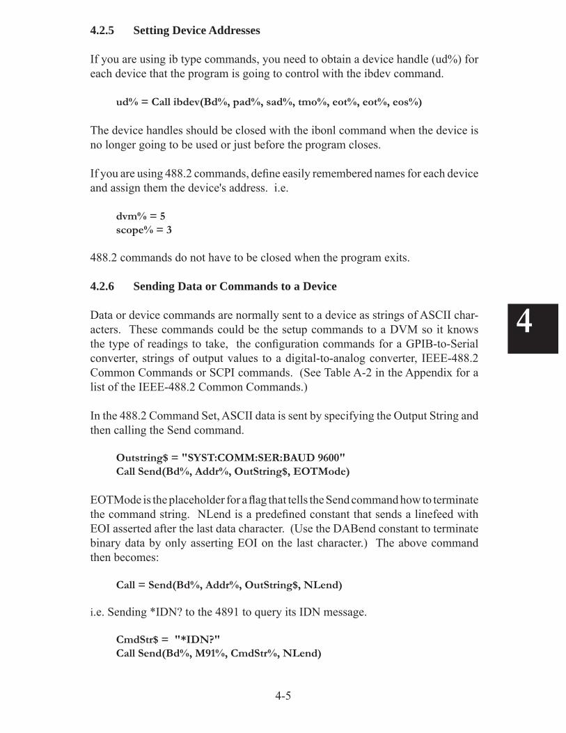
4.2.5 Setting Device Addresses
If you are using ib type commands, you need to obtain a device handle (ud%) for each device that the program is going to control with the ibdev command.
ud% = Call ibdev(Bd%, pad%, sad%, tmo%, eot%, eot%, eos%) The device handles should be closed with the ibonl command when the device is no longer going to be used or just before the program closes.
If you are using 488.2 commands, defi ne easily remembered names for each device and assign them the device's address. i.e.
dvm% = 5scope% = 3
488.2 commands do not have to be closed when the program exits.
4.2.6 Sending Data or Commands to a Device Data or device commands are normally sent to a device as strings of ASCII char-acters. These commands could be the setup commands to a DVM so it knows the type of readings to take, the confi guration commands for a GPIB-to-Serial converter, strings of output values to a digital-to-analog converter, IEEE-488.2 Common Commands or SCPI commands. (See Table A-2 in the Appendix for a list of the IEEE-488.2 Common Commands.)
In the 488.2 Command Set, ASCII data is sent by specifying the Output String and then calling the Send command.
EOTMode is the placeholder for a fl ag that tells the Send command how to terminate the command string. NLend is a predefi ned constant that sends a linefeed with EOI asserted after the last data character. (Use the DABend constant to terminate binary data by only asserting EOI on the last character.) The above command then becomes:
Call = Send(Bd%, Addr%, OutString$, NLend)
i.e. Sending *IDN? to the 4891 to query its IDN message.
All ASCII command strings should be terminated with a linefeed character and by asserting the EOI line on the last character. Binary strings are terminated by only asserting the EOI line on the last character. In the ib command set, the user has to include the terminating character in the command string.
4.2.7 Reading Data from a Device
ASCII data strings are read from a device in BASIC programs by fi rst specifying a string with blank spaces and then reading the data into the string. The input string must be specifi ed large enough to hold the expected response. In C, the string does not have to be fi lled with blank spaces.
Data is read until a terminator is found or the defi ned Input string is full. Typical terminators are linefeed or EOI asserted on the last character.
In the 488.2 Command Set the input example is:
Instring$ = String$(Lin, 75) 'fi lls the string with spacesioerr% =Receive(Bd%, Addr%, Instring$, Term)
Term is the termination fl ag used to signal the end of the data. Term can be set to any ASCII character between 0 and FF HEX and the enter process will stop when that character is detected. If Term is set to the predefi ned STOPend constant (0x256) , the enter process stops when EOI is detected. If you want Receive to stop on a character or on EOI, defi ne Term = ASCII character.
Term% = 0x0A 'for EOI and linefeed
i.e. Reading the 4891's IDN message
Instring$ = String$(Lin, 75) 'fi lls the string with spacesioerr% =Receive(Bd%, M91%, Instring$, Term)
Test the ioerr% variable after each read to be sure there were no errors.
4.2.8 Handling Binary Data
Binary data bytes can resemble any ASCII character so they are sent by assert-ing EOI on the last data byte. In the 488.2 Command Set, binary data is sent by specifying the DABend terminator when using the Send command.
Outstring$ = "bytes to be sent"Call = Send(Bd%, Addr, OutString$, DABend)
The input example uses the STOPend constant to terminate the read of binary data when EOI is asserted.
4-7
4
Instring$ = String$(Lin, 32) 'fi lls the string with spacesioerr% =Receive(Bd%, Addr, Instring$, STOPend)
4.2.9 Clearing a Device
Some devices have buffers that accumulate unwanted data and it occasionally becomes necessary to clear out the old data or to return a device to a known condition. This is done by sending the device the Device Clear Command or the IEEE-488.2 *RST command. Check your device manual for the correct command to use with your device. Device Clear is a IEEE-488.1 command that is sent with ATN asserted.
In the 488.2 Command Set this is done with :
Call DevClear(Bd%, Addr)
The *RST command is an ASCII character string and is sent as described in paragraph 4.2.4. Note that *RST is not the same as Device Clear. Check the instrument's manual for the usage of both commands with the device.
4.2.10 Triggering a Device
Some devices can initiate actions when triggered, i.e. a DVM can take a reading. There are several ways to trigger a device but in the original IEEE-488.1 Standard, a device was triggered by sending it the GET Command with ATN asserted. In the 488.2 Command Set the GET command is sent by :
Call Trigger(Bd%, Addr)
Newer 488.2 devices use the *TRG and the INIT command strings.
INIT:CONT*TRIG
The INIT and *TRG commands are ASCII strings and are output with the Send command as described in paragraph 4.2.6.
In some test programs it is desirable to trigger multiple devices at the same time. Use the 488.2 TriggerList command to address the devices that you want to trigger as Listeners and then send them the GET or *TRG command. In the ib Command Set use the ibcmd command to output the device addresses and GPIB GET mes-sages with ATN asserted.
Call ibcmd(bud%, "\x3F\x24\x25\x08") 'VB exampleibcmd(bud%, "\x3F\x24\x25\x08",4) 'C example 'sends unlisten, listen 4, listen 5 and GET
4-8
4
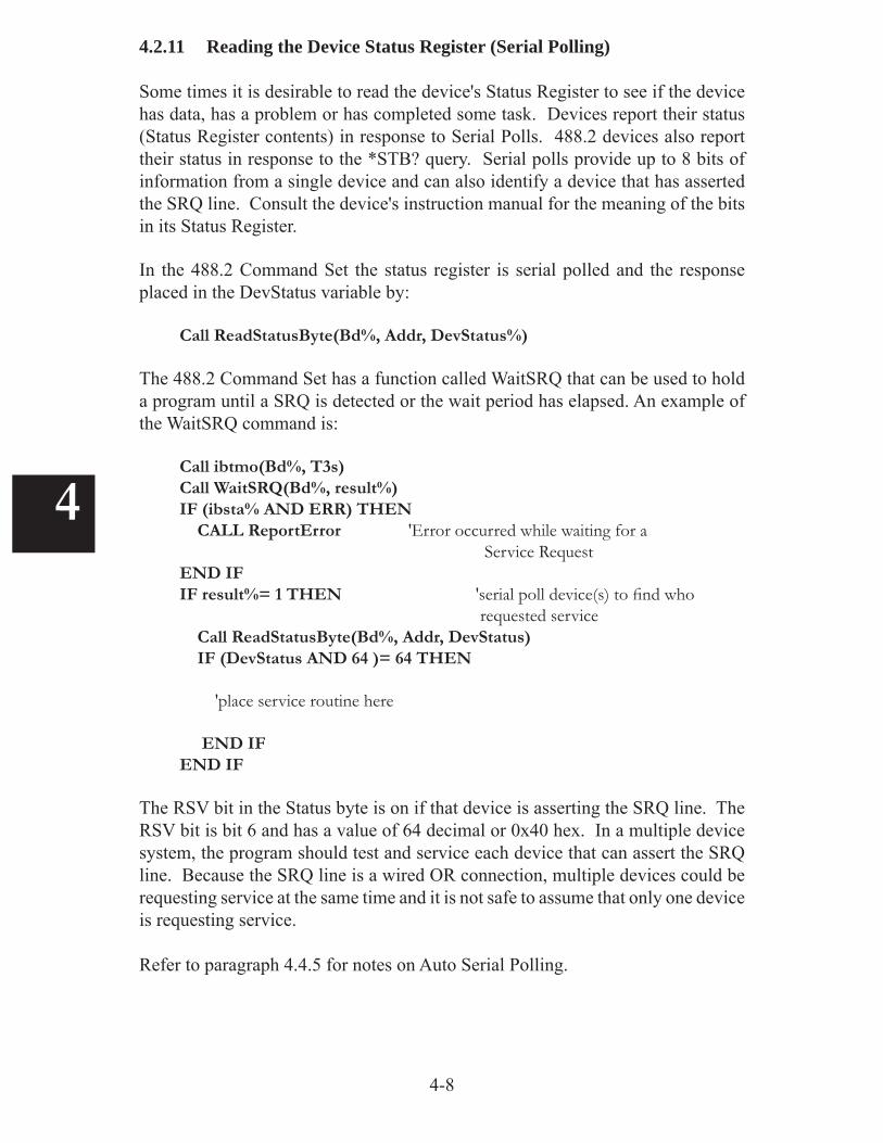
4.2.11 Reading the Device Status Register (Serial Polling)
Some times it is desirable to read the device's Status Register to see if the device has data, has a problem or has completed some task. Devices report their status (Status Register contents) in response to Serial Polls. 488.2 devices also report their status in response to the *STB? query. Serial polls provide up to 8 bits of information from a single device and can also identify a device that has asserted the SRQ line. Consult the device's instruction manual for the meaning of the bits in its Status Register.
In the 488.2 Command Set the status register is serial polled and the response placed in the DevStatus variable by:
Call ReadStatusByte(Bd%, Addr, DevStatus%)
The 488.2 Command Set has a function called WaitSRQ that can be used to hold a program until a SRQ is detected or the wait period has elapsed. An example of the WaitSRQ command is:
Call ibtmo(Bd%, T3s)Call WaitSRQ(Bd%, result%)IF (ibsta% AND ERR) THEN CALL ReportError 'Error occurred while waiting for a Service RequestEND IFIF result%= 1 THEN 'serial poll device(s) to fi nd who requested service Call ReadStatusByte(Bd%, Addr, DevStatus) IF (DevStatus AND 64 )= 64 THEN
'place service routine here END IFEND IF
The RSV bit in the Status byte is on if that device is asserting the SRQ line. The RSV bit is bit 6 and has a value of 64 decimal or 0x40 hex. In a multiple device system, the program should test and service each device that can assert the SRQ line. Because the SRQ line is a wired OR connection, multiple devices could be requesting service at the same time and it is not safe to assume that only one device is requesting service.
Refer to paragraph 4.4.5 for notes on Auto Serial Polling.
4-9
4
4.2.12 Reading and Writing Large Files
Many times the user has to transfer large fi les to or from a device. Typical ap-plications are outputting large fi les to a Waveform Generator or reading data fi les from a Signal Analyzer.
The ibrdf and ibwrtf commands let the user transfer data directly to and from fi les. The user creates two fi les, one for outgoing data (outtext.txt) and one for incoming data (intext.txt). The fi les can be created with Notepad or any application. Data etc. must be put into the outtext.txt fi le before it is transferred to the GPIB device. The user will also have to send the device any necessary setup commands the device requires. The fi le transfer commands are:
CALL ibwrtf(ud%, "outtext.txt") 'writes out fi le to deviceCALL ibrdf((ud%, "intext.txt") 'reads data from the device to the in fi le
ud% is a device descriptor which is obtained with the ibdev command.
The 488.2 Send and Receive commands can also be used to transfer large blocks of data to and from a device. The Send and Receive commands use the Bd% and dev% (addr%) type variables instead of the ud% handle to defi ne the device so they are easier to use. The following Send and Receive examples handle binary data. You can change the Visual Basic GET and PUT fi le transfer commands if you are using just ASCII characters.
DIM Outbuf as String * 7000 'defi ne proper size buffersDIM Inbuf as String * 10000
OPEN "outtext.txt" FOR RANDOM AS #1 Len = recordlen 'opens output fi leGET 1, 1, Outbuf 'reads text fi leCALL Send(Bd%, addr%, Outbuf, DABend) 'outputs data CLOSE #1 'close the fi le
OPEN "Infi le" FOR BINARY AS #1 'opens fi le for input dataCALL Receive(Bd%, addr%, Inbuf, STOPend) 'reads data from device to bufferINPUT #1, Inbuf 'transfers data to fi leCLOSE #1 'close fi le
4-10
4
4.2.13 Sending Bus Commands to a Device
Sometimes it is necessary to send Bus Commands to a device to address a de-vice as a talker or as a listener or to set it into a special confi guration mode. Bus commands are single character commands that are sent to a device with ATN on. Multiple commands can be sent in the same command string. Refer to Table A-1 in the Appendix for a list of GPIB Bus Commands.
The 488.2 Command Set uses the alphabetical characters in Table A1 as place-holders for the GPIB commands. The escape sequence for CYberResearch serial adapters requires that it be sent Unlisten, Listen Unlisten without sending it any data. Assuming the device address is at 4 the escape string is:
The 488.2 SendCmds function outputs the bytes passed to it in CmdStr$ onto the GPIB bus with ATN asserted.
4.2.14 Parallel Polling GPIB Devices
Parallel Polling reads the status of up to eight confi gured devices in one byte. It is a fast method of reading a status bit from multiple devices but it provides only limited information about each device. Because of its limited usefulness, most new devices do not have Parallel Poll capability. Parallel Polling is not supported by CyberResearch' 488.2V3 Driver but the discussion is included for completeness.
Before a device can be Parallel Polled it must be confi gured so that it will respond by asserting a specifi ed data bit when polled. Devices that can be confi gured from the GPIB Bus have a PP1 capability. Devices that can be confi gured internally have a PP2 capability. The meaning of the reported status bit is determined by the device designer. In the 488.2 Command Set, the bit selection and polarity are two variables. The Confi guration Commands are:
Call PPollConfi g(Bd%, Addr%, Bit%, sense%) 'bit% is 0 to 7, sense = 0 for false and 1 for true.
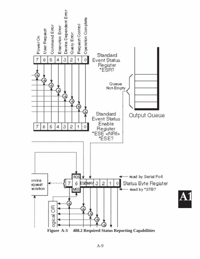
The IEEE-488.2 Standard standardized the data transfer protocol between the GPIB Controller and devices, added an expanded Status Reporting Structure to devices, added a set of Common Commands that a device must respond to and added Controller protocols for handling multiple devices. These changes are described in paragraph A1.2 of the Appendix.
The expanded reporting structure in IEEE-488.2 devices includes an Standard Event Status Register which supplies additional information about the device's status. This additional information is contained in the Standard Event Status Register whose conditions are summarized in bit 4 in the existing Status Byte Register. Figure A-3 in the Appendix shows this minimum IEEE-488.2 Status Reporting Structure. A 488.2 device designer is allowed to add additional registers which can be sum-marized into the Status Byte Register. The *ESE and *SRE Common Commands set bits in enable registers so an on condition of a corresponding event bit will be reported in the Status Register and can be used to generate a SRQ and to interrupt the GPIB Controller. Review your device's manual for specifi c information on its capabilities before programming the device.
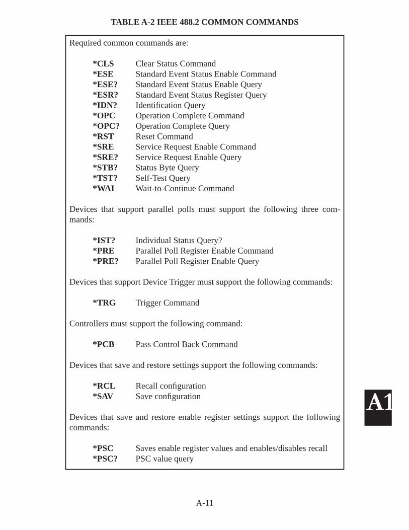
The required Common Command set simplifi es GPIB programming since all IEEE-488.2 compatible devices respond to a minimum set of Common Commands and behave in a defi ned manner. The IEEE-488.2 Common Commands are defi ned in Table A-2 of the Appendix. Note that older IEEE-488.1 devices may or may not respond to any of the Common Commands so check the device's manual before using them in your program.
4.3.1 Common Commands
The IEEE-488.2 Common Command set adds ten new commands to all 488.2 compatible devices and also provides some new ways to do things that were done in the original IEEE-488 Standard. The most frequently used commands are:
*IDN? query reads the device's IDN message which identifi es the device's Manufacturer, Model Number, Serial Number and Revision.
*ESR? query reads errors and status from the Event Status Register.*TRG command triggers a device similar to the original GPIB GET command.*STB? query reads the Status Byte but the RSV bit in the Serial Poll response
is replaced by the MSS bit defi nition.
The *IDN? query is commonly used to test the GPIB connection to a device since it provides a quick identifi cation of the device and verifi es that the GPIB connection is working at the same time. A complete list of the 488.2 Common Commands and their defi nitions is shown in Table A-2 of Appendix 1.
4-12
4
4.3.2 Confi rming a Device's Presence
IEEE 488.2 compatible devices respond to the *IDN? query with a response (up to 72 characters long) that identifi es the device manufacturer, device model number, its serial number and revision. The *IDN? query is a good way to verify that the device is available to your system when starting a program. If you run FindLstn fi rst, you can use the IDN query to check the ResultList to fi nd the addresses of the device(s) you want to use in your program. The 488.2 Command Set example is:
The IEEE-488.2 FindLstn Protocol returns a list of all active devices on the bus that can be addressed as listeners. FindLstn creates a list that then can be used by the other protocols to perform serial polls or to reset all of the devices on the bus.
CAUTIONPresence of a device on the bus that handshakes all data bytes such as a bus analyzer, bus extender, bus expanders or a listen-only device will cause the FindLstn command to fi nd all possible primary device addresses. In this case, the user should supply a list of the actual devices on the bus, not all possible devices, before executing the FindLstn command.
RECOMMENDATIONSet the timeout to ≤ 500 milliseconds when using the 488.2 protocols with large device lists to prevent unnecessary program slowdowns. Reset it back to its original value when done.
The 488.2 FindLstn example is:
FOR I = 0 to 30 'generate a AddrList AddrList(I) = (I)NEXT IAddrList(I+1) = NOADDR numDevices = 31 'set max number of devicesCall = FindLstn(Bd%, AddrList, ResultList, numDevices)
The user should read the address list after executing the FindLstn command to verify presence of all known devices and the absence of any phantom device addresses. Refer to the Command Reference Section for detailed information on the address list format and for directions on passing the address list to the 488.2 Driver.
4-13
4
4.4 PROGRAMMING NOTES AND SUGGESTIONS
4.4.1 Windows Restrictions
While the 488.2V3 Driver supports multiple cards (and GPIB buses), there is no hardware or software locking. Users should take care to not run multiple applica-tions that access the same GPIB Controller card at the same time.
4.4.2 Timeout Usage
Due to the nature of the Windows multi-tasking environment, if a user sets the bus handshake timeouts too short, another application could use up the allotted time, thereby creating false errors. If the user sets the handshake timeouts to infi nity (zero), then a bus problem could hang the system in the GPIB application. The recommendation is to use a 1, 3 or 10 second timeout setting.
4.4.3 Create Query Subroutine
Much of your GPIB programming can be simplifi ed by creating subroutines to handle repeated tasks. The most common task in most programs is outputting a command string and reading back the optional response. In the following ex-ample, Sout outputs the command string passed to the specifi ed device and returns any response. This routine works since most queries to a 488.2 device include a question mark.
i.e Querying the DVM's ESR Register.
Public Rdg$ 'Sout response string
Cmd$="*ESR?" 'main line call-reads ESR registerCall Sout(DVM%, Cmd$)
Sub Sout(addr%, CmdStr$) 'subroutine Call Send(Bd%, addr%, CmdStr$, NLend) If INSTR$(CmdStr$, "?") <> 0 then Rdg$ = String$(80," ") 'prefi ll input string Call Receive(Bd%, addr%, Rdg$, STOPend) Rdg$=Rtrim$(Rdg$) 'removes right hand spaces End ifEnd Sub
The user should add error checking to the above example before including it in a program.
4-14
4
4.4.4 Waiting for GPIB Conditions
The ibwait function can be used to hold the application until an event occurs or to immediately return a status response. If ibwait is called with a zero mask value, it updates the ibsta value and returns immediately. If ibwait is called with a non-zero mask, then the application waits for one or more of specifi ed events to occur. Always include the TIMO bit in the ibwait mask to avoid permanently hanging the application.
4.4.5 Automatic Serial Polling
Automatic serial polling is a function of the 488.2 driver whereby the library issues a serial poll if SRQ is asserted. Each positive serial poll response (bit 6 asserted or the hex 40 bit set) is stored in a queue associated with the device that was polled and the RQS bit in ibsta is also set. Auto serial polling continues until SRQ is unasserted or until an error condition is detected. If ibrsp is called, it reads the queued response instead of serial polling the device. If the queue is empty, ibrsp serial polls the device.
If SRQ is still asserted after the 488.2 Driver has Serial Polled all open devices, the SRQ is considered stuck. If this happens, no further auto Serial Polls are attempted until the stuck state is cleared by calling ibwait for RQS.
The 488.2 Driver can perform Auto Serial Polls even when interrupts are enabled providing that no other GPIB commands are in progress or when a device-level ibwait for RQS is in progress. Auto Serial Polling is disabled when the user calls an 488.2 function and re-enabled again after an 'ib' type function is called.
Auto Serial Polling is required for LabView and for some mask conditions in ibwait and ibnotify. If these functions are not being used in your program, Auto Serial Polling should be left disabled.
Auto Serial Polling is enabled in the Explorer-Confi gure form by checking the Auto Serial Polling Enable checkbox or by calling ibconfi g with option IbcAU-TOPOLL.
4.4.6 Asynchronous Event Notifi cation
Win32 C language applications can asynchronously receive event notifi cation when a specifi ed event occurs on the GPIB bus. This is done by setting the desired GPIB events in a mask and calling the ibnotify function. An example is waiting for a GPIB device to assert its service request line. When the GPIB device requests service, the GPIB driver automatically notifi es the application that the event occurred by executing a Callback function that was specifi ed when ibnotify was called.
4-15
4
ibnotify syntax is:
Ibnotify (int boarddev, int mask, (__std call *user_callback_routine), void *RefData)
where boarddev is an integer containing the device handle. mask is a bit mask of the watched GPIB events, see Table 6-3. user_callback_routine is a pointer to the callback function. RefData is the user defi ned reference data for the callback.
Both board and device-level calls are supported by the GPIB driver. For board-level calls, boarddev is the board handle and the mask can be any value but must not include the RQS or ERR bits. For device-level calls, boarddev is the device handle and the mask can contain the RQS, CMPL, END or TIMO bits. (Always include the TIMO bit to avoid hanging the application).
The user_callback-routine registered with the ibnotify call is invoked by the GPIB driver when one or more of the specifi ed events becomes or is true. The Callback function is:
int __stdcall user_callback_routine(int boarddev, int ibsta, int iberr, long ibcntl, void *RefData) {....}
The user_callback-routine is passed a unit descriptor, the current ibsta, iberr and ibcntl values and the user defi ned Reference Data from the original ibnotify call. If the return value is nonzero, the GPIB driver uses it as the mask to rearm the callback function. A zero value stops the rearm process.
Note: The ibnotify callback is executed in a separate thread of the application. If the application may be performing other GPIB functions while waiting, use the per-thread GPIB global variables that are provided by the Threadibsta, Threadiberr, Threadibcnt and Threadibcntl functions. If the application needs to share any global variables with the callback function, then you must protect access to the variables to prevent unwanted updating of the variables. Refer to Application Bulletin AB48-32 for a detailed ibnotify example.
4.4.7 Multithreaded Applications
Win32 GPIB applications are normally written with one thread that uses the ibsta, iberr, ibcnt and ibcntl global variables in a time sequential manner. Multithread applications with GPIB calls from two or more threads need a method to protect the global variable from unwanted changes. This is done by one of the following methods:
1. Synchronize access to the process-global variables2. Do not use the process-global variables.
4-16
4
Synchronization can be achieved by setting a semaphore before making the GPIB call and then releasing the semaphore after examining the global variables. If the semaphore is set, the other thread processes wait for it to be cleared before mak-ing a GPIB call.
Alternately, use separate variables for each thread that are maintained by the driver. These per-thread variables can be accessed with the following functions:
int Threadibsta()int Threadiberr()int Threadibcnt()long Threadibcntl()
An example of using the per-thread variables is in the common error check line
if (ibsta and ERR)
Replace it withif(Threadibsta() and ERR)
Add the following #defi ne lines to the application to use the per-thread global variables:
#defi ne ibsta Threadibsta()#defi ne iberr Threadiberr()#defi ne ibcnt Threadibcnt()#defi ne ibcntl Threadibcntl()
Another alternative is to create a set of variables in the thread that the GPIB library will automatically update. This is done by calling RegisterGpibGlobalsForThread early in the thread code. RegisterGpibGlobalsForThread registers four local thread variables to receive the global GPIB status information for each GPIB call by the thread. The user's code can easily examine the local variables after any GPIB call to check status. UnregisterGpibGlobalsForThread(void) is called to release the thread variables before the thread is closed.
The Support CD-ROM includes example .NET Controller Programs for Visual Basic.NET and for C. These programs are installed in the Program Files\Cyber-Research\DemoSoftwarePrj\Ctlr Samples\ directory. The Ctlr Samples directory has subdirectories for BV.NET and C# programs.
4.5.1 Visual Basic Demo Program Example
The VB_demo program is a simplifi ed version of CyberResearch's GPIBkybd program. It is written with the 488.2 Command Set and includes the most com-monly used GPIB commands. It makes a good starting place for a Visual Basic.NET program since it has all of the elements necessary to control GPIB devices.
Figure 4-2 VB Demo.NET Control Panel
When the program starts, all of the controls are grayed out except for Initialize which initializes the GPIB Controller and performs a FindLstn to see what devices are connected to the GPIB Bus. At this point all Controls are active. The user can select a different GPIB device by entering its GPIB address in the Device Address window and pressing Set.
The included functions are:GPIB Controller InitializationSend IFCDevice Clear
4-18
4
Serial PollSending Command StringsReading Device Responses
The VB_demo program also includes a FindLstn protocol example. This example is helpful if you want an easy way to check the bus for active devices or if you want to generate a list for later use with another 488.2 protocol. Creating the ini-tial address lists is not always obvious. You can generate the list with all possible primary addresses as is done in VB Demo if there are no listen-only devices in the system. Else limit the devices in the initial address list to just the known possible devices that are connected to the system.
The VBDemo.NET program was originally a Visual Basic 6 program that was converted to a Visual Basic.NET program. Visual Basic.NET programs require two new .vb fi les to run and link to the GPIB-32.DLL. The new fi les are:
GPIB-32.vb GPIB Library FileICSVB.vb File contains constants and gpiberr routine
New programs need to have these fi les added to the project. Updated programs will need to have converted fi les replaced by the ones supplied by CyberResearch.
4.5.2 Converting a Visual Basic 6 Program to a .NET Program
A Visual Basic program developed with Microsoft's Visual Studio 6 can be eas-ily updated to run as a .NET program by the following steps. Older Visual Basic programs should be updated to version 6 programs before converting.
1. Prepare your Visual Basic program for conversion to VB.NET by making sure that all variable defi nitions are correct. Type OBJECT variables are not supported in .NET and must be changed to another type. Be sure your program runs without errors and that all variables are initialized.
2. Save the program in Visual Studio 6. This will automatically make it a VB6 program.
3. Open the program in Visual Studio 2005. Save the converted project and fi les in a new directory.
4. Use the Project menu to delete the GPIB-32.BAS and ICSVB.BAS fi les in the new directory.
5. Copy CyberResearch's GPIB-32.VB and ICSVB.VB fi les into the new directory with the converted fi les.
4-19
4
6. Use the Project menu to add GPIB-32.VB and ICSVB.VB to the project.
7. Fix the conversion errors. The majority of errors will be unreferenced functions and variables as indicated by the light blue squiggly underline. Look at the heading at the top of the GPIB-32.VB fi le to get the correct class reference. Add the class reference to the command and variable names. i.e.
Call Send (..) becomes
Call GPIBFuncs.Send(...)
8. Correct the remaining errors. Save the corrected project and forms often as you do the edits.
9. Run Build and repeat step 8 to fi x the remaining errors.
10. Use the Debug menu to start and test the program. Any associated data fi les need to be placed in the BIN subdirectory with the .exe program or else referenced correctly.
4.5.3 C Example
An example ANSII C program is included in the C++ subdirectory. The program is called CYR_Demo and was built in Microsoft Visual Studio version 6. The
Figure 4-3 CYR_Demo Program
CYR_Demo is a text line program that asks the user for the device address when it opens and then gives the user a choice of several GPIB commands that he can execute. The example GPIB commands are typical of the commands a user will
4-20
4
need in his program. Each command shows the user how that command is pro-grammed in C. The user can use the example C program as the starting point for his program.
New C programs will have to include the "#include "ICSDecl.h" statement and link to the latest GPIB-32.LIB library fi le.
4.5.4 Converting a C Program to a .NET Program
The example program is a version 6 C program that was developed in Visual Studio 6. The example is easily converted to a .NET compatible version by the following steps:
1. Be sure your program runs without errors and that all variables are properly initialized.
2. Save the program in Microsoft Visual Studio 6. See the Visual Studio 2005 Help fi le for what other versions of C programs that Visual Studio 2005 can update.
3. Open the program in Visual Studio 2005. Save the converted project and fi les in a new directory.
4. Build. Correct any errors.
4.6 PROGRAM TROUBLESHOOTING TECHNIQUES
This section provides the GPIB programmer with some suggestions for troubl shooting his or her program. It is assumed that the GPIB Controller has been suc-cessfully installed and tested prior to writing your program.
4.6.1 Common Faults
GPIB Card Initialization - Program fails to properly initialize the GPIB Controller. Check programming examples for proper method of initializing the GPIB Card. The method varies with the chosen command set used in the program.
Addressing errors - 'ib' type commands use ud handles to address devices, bud handles to address the board and boarddev handles when the command can address a board or a device. Confusing these handles is a common error.
Visual Basic reading failure - Visual Basic and other Basic languages require that the user fi rst fi ll the input buffer with enough spaces to accommodate the longest expected string before calling the input instruction. Using a short buffer$ set to "" will not work.
Query errors - GPIB devices are disciplined devices that only output data when
4-21
4
addressed to talk. They can only be read when they have something to output such as a reading. A query error occurs when the user tried to read when the device has nothing to output or sending the device a new command and not reading the data collected by a earlier command.
Lack of understanding how the device works - User is often ignorant of how the device reports its status, if it has a Status Register or an event Status Register and how these registers are used. User should take a moment to read the device manual to learn its reporting capabilities.
Not testing or clearing error registers - User should design his program to check a device for errors after sending it a group of setup commands. Use the *ESR? query with 488.2 instruments. Display any failure message to the operator.
Not verifying that all instruments are powered on and connected at the start of the program - Don't let the user get way into the program before fi nding that a device does not respond because it is not powered on. An easy way to do this is to query each devices' IDN message and to check the result string for the expected model number at the beginning of the program.
Instruments not setup correctly - Someone may have switched instruments or taken one out for calibration and not set it back to your expected confi guration. Avoid this problem by including all setup parameters in the program.
Not applying timeouts when waiting for instrument responses - This leaves the program in a hung condition and unable to do anything until the instrument replies. If it never replies or if the reply is not recognized, the program is dead. Use timeouts to keep from being hung waiting for an instrument response. Put counters in loops that make repeated queries waiting for an instrument or signal state change.
Not checking for GPIB errors after each command - Unexpected errors can cause problems later on in the program or when the program is run at a later time. The solution is to test for errors after each command. A second method is to look at the returned status values in CYR SPY to catch program errors. Single step or provide a few breakpoints and then scroll through the CYR SPY buffer for errors. See paragraph 4.6.2 for how to use CYR SPY.
Not error checking operator input - Bad inputs can lead to unexpected results. Good programming practise is to limit check input data before using the input in your program.
4.6.2 CYR Spy Program
Figure 3-1 shows how application programs control the GPIB bus by calling the GPIB-32.DLL. CYR SPY is a utility that communicates with the GPIB-32.DLL. When CYR SPY runs, it reports on calls to the DLL and on the DLL's responses to
4-22
4
the application program. Each response includes the ibsta and iberr return values. With CYR SPY you can see the returned status for each one of your program calls, even if you did not check them in your program.
CYR SPY is installed in the Utilities folder as part of the 488.2V3 installation.
When the CYR SPY program is run, it opens a DOS window that the user can resize and put in a corner of his screen. (The lower right corner is recommended.) When a GPIB application accesses the GPIB-32.DLL, the CYR SPY window displays an attached message as the process attaches to the DLL. Each call is shown along with the updated Global Status Variables (ibsta, iberr, ibcnt and ibcntl). As long as the returned ibsta value is less that 0x8000, there are no errors. An ibsta value greater than 0x8000 indicates an error. Tables 6-6 and 6-7 in Section 6 list the ibsta and iberr values and their meanings.
While CYR SPY does not have a print capability, the user can copy the text from CYR SPY to a Windows Notepad. The Notepad fi le can be either printed or emailed to another party.
4.7 TEST AND MEASUREMENT PROGRAMS
The following paragraphs provide instructions for using CyberResearch's 488.2V3 Driver and GPIB Controllers with the more popular Test Programs. A4.7.1 VISA Libraries
VISA Libraries provide an industry standard api so test programs can run with any manufacturers' hardware. The VISA libraries are command drivers that convert program independent VISA calls into manufacturer dependent calls. Figure 4-4 shows this schematically. Newer versions of LabView, Agilent's (HP) VEE and many other applications like MATLAB make VISA calls so that they are hardware independent and can be used with multiple company's GPIB Controller cards. VISA calls can also be made by Visual Basic and C language programs.
4-23
4
GPIB Hardware
GPIB-32.dll
Device Driver
Win 32 Applicationswith NI or ICS Cmd Set
Windows Interface
GPIBkybdProgram
VISADriver
AgilentVEE
NILabView
Win 32 Applicationswith VISA calls
VISA InteractiveControl
Gray boxes are test utility programs.
Figure 4-4 Simplifi ed VISA-GPIB-32.DLL Diagram
4.7.1.1 VISA Installation
If you have purchased and installed LabView, you probably have installed NI's VISA Driver as part of their installation program. If you use Agilent Instruments or Agilent (formerly HP) VEE, you can download a Visa Library from their website as part of their I/O Library Suite. Follow the Agilent directions to install Agilent VISA. Make it the primary VISA if you are running VEE or other Agilent software.
4.7.2 National Instruments LabView and MAX
LabView is a popular graphical programming environment from National Instru-ments (NI) that comes with many instrument drivers that simplify the programming of large test and measurement applications. NI's Measurement and Automation Explorer (MAX) is an interactive control utility for NI's latest GPIB Controllers and does not recognize some NI and other manufacturers GPIB Controller cards. All of CyberResearch's GPIB Controllers covered by this manual can be used to run LabView but will not necessarily work with MAX.
4.7.2.1 Installing LabView with CyberResearch's 488.2V3 Drivers
CyberResearch's GPIB Controllers can run LabView programs by overlaying NI's NI488.2 Driver with CyberResearch's 488.2V3 Driver. The recommended instal-lation method is to fi rst install LabView. (If you already have CyberResearch's 488.2V3 Drivers installed, you should uninstall them at this time.) When you run the LabView installation program, it places a VXIPNP directory on the root direc-tory and VXIPNP in the Program menu. Answer NO when asked if the installation program should install the GPIB driver. When done, install the latest version of
4-24
4
CyberResearch's 488.2V3 Drivers by downloading them from CyberResearch's website. Run CyberResearch's Explorer and use the Confi gure utility to enable 'Auto Serial Polling' by checking the associated box. Run the CYR_NI_Support_Install program which is located in the ..\Program Files\CyberResearch\Utilities directory. Verify the operation of the VISA Driver as described below in paragraph 4.7.2.2.
4.7.2.2 Testing the VISA Drivers
The VISA driver needs to be tested to be sure that it can fi nd CyberResearch's GPIB-32.DLL before running a program that makes VISA calls. Connect your GPIB Controller card to a IEEE-488.2 GPIB Device. Verify that the device responds to an *IDN? query from Explorer.
Test the VISA layer operation by running the NI VISA Interactive Control utility. START>PROGRAMS>National Instruments >VISA>VISA Interactive Control. The VISA Interactive Control will start and after a minute open a window show-ing the GPIB Controller Card (GPIB0) and the GPIB Device. Double-click on the Device to open its window. Click on the Instrument Basic I/O tab to open the control window. The Write tab opens with the '*IDN?\n' query already in the buf-fer. If this is LabView 8 or 8.2, uncheck the ASYNC box if it is checked. Select the Read tab and click Execute to read the response back from the device. Again if you are using the LabView 8 or 8.2, uncheck the ASYNC box. Use the same technique to send additional commands though the VISA layer to the device. Exit the VISA Interactive Control Panel when done. At this point, NI VISA is working and your LabView programs should run.
4.7.2.3 Testing MAX Compatibility
National Instruments has been reworking their Measurement and Automation Ex-plorer (MAX) so it only recognizes recent NI GPIB Controllers. Early NI Controllers and other vendors GPIB Controller cards are not recognized by MAX.
If you have version, 1.7, you may use it to replace your current version of MAX. Max version 1.7 does recognize CyberResearch's GPIB Controllers. CyberResearch's USB GPIB Controllers will appear under Devices and Interfaces. Select GPIB0, right click on it and select Scan for Instruments. Highlight an instrument. Use Communicate with Instrument to send it a query and read back a response. If you selected an IEEE-488.2 compatible instrument, you can test it with the '*IDN?' query. Once you can read from and write to an instrument, you have a working MAX.
4.7.3 Agilent Software
Agilent (formerly HP) has several Test and Measurement oriented software pack-ages that can be used with CyberResearch's GPIB Controllers. The method varies depending upon which version of their software you are using.
4-25
4
4.7.3.1 Agilent IO Libraries Version 14.2
This is a new GUI version that includes a VISA library that directly communicates with CyberResearch's GPIB-32.DLL. You can install it per their instructions and it will fi nd and use CyberResearch's GPIB Controller. You do not need to install the NI VISA with version 14.2.
Version 14.2 does have a few problems. Its error handling is not robust and its Auto Discovery will not work with all devices. Auto Discovery and Auto Identify options should be turned off when using version 14.2.
Version 14.2 provides a tree structure that shows you the LAN (TCPIPO) and Re-mote (GPIB0) Devices connected to the system. LAN (TCPIPO) communicates directly to VXI-11.3 compatible instruments. Remote (GPIB0) communication is through a VXI-11 compatible Gateway.
For Remote (GPIB0), leave Auto Discover off. Enter gpib0 as the interface name of the remote host. Under GPIB device properties, leave Check for Instruments and Auto Identify unchecked.
4.7.3.2 Agilent IO Libraries Versions 14.1 and Earlier
These versions rely on fi nding a National Instrument's NI-488.2 driver on your computer. They connect by selecting 'GPIB using NI'. Before you install the Agilent software, you should prepare your system as follows.
1. If the NI-488.2 is not installed on your computer you will need to install it. Locate NI-488.2 (Win32) Version 1.70 for Windows 2000/95/98/ME/NT/XP on National Instrument’s website (www.ni.com) and download it. Run the download fi le to install the NI driver.
2. Install the latest version of CyberResearch's 488.2V3 Driver by downloading it from CyberResearch's website. Run CyberResearch's Explorer to initialize the GPIB Controller.
3. Connect a GPIB device to your GPIB Controller. Test CyberResearch’s driver with Explorer to be sure CyberResearch's driver is working.
5. Add a pseudo NI device to the system. For CyberResearch’s USB Controllers running on Win 2K , XP or VISA32 this is done by running CYR_NI_Support_Install. CYR_NI_Support_Install is located in ..\Program Files\CyberResearch\Utilities directory.
5. If you installed NI 488.2 ver 1.7 they you can test MAX to verify that the NI-488.2 driver is working. See paragraph 4.7.2.3.
4-26
4
You are now ready to install the Agilent Software.
4.7.3.2.1 Version 14.0
Agilent has several older versions of their IO Libraries that simplify communication from your computer to various Test and Measurement devices. Version 14 has an installation program that does the installation and searches for the GPIB Controller and instruments. It should automatically fi nd the CyberResearch GPIB Controller if you completed the above steps prior to installing the IO Library.
4.7.3.2.2 Version M
The M version of the IO Libraries is found in Agilent's Library Archive fi le. The M version is needed for Intuilink and may be needed for older versions of VEE. When installing an older version of the IO Libraries, select install Agilent VISA as the second VISA when asked. After the installation, run IO Confi g and select ‘GPIB using NI-488.2’. This should put a GPIB0 entry in the right hand window. After that, you can scan for instruments and proceed using the Agilent IO Libraries.
4.7.3.3 Agilent VEE
VEE is a graphical programming environment from Agilent that comes with many instrument drivers that simplify the programming of large test and measurement applications. All of CyberResearch's GPIB Controllers covered by this manual can be used to run Agilent VEE.
Early versions of VEE made direct calls to the GPIB-32.DLL. Later versions make Agilent VISA calls which in turn calls NI's VISA and then CyberResearch's GPIB-32.DLL. The newest version (14.2) uses a VISA layer that is compatible with CyberResearch's GPIB-32.DLL.
Use Explorer to enable 'Auto Serial Polling'. Run VEE. In VEE set the primary GPIB device addresses between 1400 and 1430.
4.7.3.4 Agilent Intuilink
Intuilink can be downloaded and installed from Agilent's website. When run, Intuilink’s IO Confi g will scan your system and fi nd your GPIB Controller. Se-lect ‘GPIB using NI-488.2’ and click the Confi gure button and then OK. Exit the IO Confi g routine. You now have a connection to your CyberResearch GPIB Controller.
4-27
4
4.7.3.5 Agilent Benchlink
Benchlink was designed to work with specifi c HP Oscilloscopes. Load Benchlink and upgrade it to version 1.5. If Benchlink fails to fi nd your oscilloscope you can manually edit the Benchlnk.ini fi le as follows:
1. Find the Benchlnk.ini fi le (typically in C:\WINNT) and make a backup copy.
2. Set the “InterfaceCard=” line to read InterfaceCard=National Instruments AT-GPIB
3. Set the “IDNDisable=” line to skip all GPIB addresses but your scope address. If your scope is at address 7 then set
IDNDisable=1,2,3,4,5,6,8,9,....28,29,30
4. Set the “ScopeModel=” line to your scope model.
5. Set the “Points=” line to the number of points to be read. Model number and points should match what is in the scope defi nition section of the fi le.
Save the edited Benchlnk.ini fi le. Next, fi nd the HPIB.DLL fi le (typically in C:\WINNT) and rename it to oldHPIB.DLL. Run Benchlnk and it should fi nd your scope and display its model number in the menu bar window. If it doesn’t display the correct name and model, you may have to adjust the INI fi le settings.
4.7.4 CEC Testpoint
CEC's Testpoint is a graphical programming environment that offers an alternative programming method to National Instruments LabView and HP VEE. Testpoint as shipped may only run with CEC and Keithley GPIB controller cards but will run with CyberResearch's GPIB Controller cards when CEC's optional National Instrument's GPIB library is installed. Testpoint also makes VISA calls and can communicate to CyberResearch's GPIB Controllers through the NI or Agilent VISA library.
4.7.5 MATLAB
MathWorks' MATLAB is a high-level language and interactive environment that enables you to perform computational intensive tasks faster than with traditional
4-28
4
programming languages such as C, C++, and Fortran. MATLAB users can commu-nicate with CyberResearch's GPIB Controllers by using the MathWorks Instrument Control Toolbox ver 1.2 or later. This allows you to control and talk with electronic and scientifi c instrumentation directly from the MATLAB environment.
4.7.6 Transera HTBasic
HTBasic emulates HP 9000/200 and other HP computers so that you can run HP Basic or Rocky Mountain Basic programs in a PC and control your GPIB devices. Load and run Transera’s HTBasic per their instructions. Select and load their GPIBNI driver to link HTBasic to the GPIB USB’s GPIB-32.DLL. This can be done from the HTBasic Tools menu tab by selecting Device Setup and then click-ing the 'Add' button to open a Device Selection window. Next select GPIBNI and click 'Add' to add the device and close the window. Finally highlight the GPIBNI interface and click 'Load' to load the driver. Run your HTBasic program and it will automatically use your GPIB USB to communicate with your GPIB devices.
4.8 CONVERTING EXISTING PROGRAMS
4.8.1 Visual Basic Programs
Normally, Visual Basic language programs written for National Instruments GPIB Cards will run on CyberResearch's GPIB Controllers. The original executable fi le should run without any changes. If you are making changes to a 32-bit, Visual Basic Windows program written for the National Instruments GPIB cards, the program can be recompiled with the existing National Instrument's NIGLOBAL.BAS and VBIB.BAS fi les and run on CyberResearch's GPIB Controller cards. Alternately the National Instrument .BAS fi les can be replaced with CyberResearch's GPIB-32.BAS and ICSVB.BAS fi les. Be sure CyberResearch's 488.2V3 Driver is installed and running with the GPIB devices before running the Visual Basic programs.
To update a 16-bit, Visual Basic Windows GPIB program written for the National Instruments GPIB cards, the program must be recompiled with CyberResearch's or National Instruments 32-bit libraries as described above. This will convert the program to a 32-bit program. Be sure CyberResearch's 488.2V3 Driver is installed and tested before running the converted program.
4.8.2 C Language Programs
Normally, C language programs written for National Instruments GPIB Cards will run on CyberResearch's GPIB Controllers. If you are making changes to a
4-29
4
32-bit, C language Windows program written for the National Instruments GPIB cards, the program should be recompiled with CyberResearch's ICSDECL.H fi le included in place of National Instrument's DECL-32.H header fi le and linked with the GPIB-32.LIB library in place of National's GPIB-32.OBJ fi le. The program then requires CyberResearch's GPIB-32.DLL to run. Be sure CyberResearch's 488.2V3 Driver is installed and running with the GPIB devices before running the C language programs.
If you have a 16-bit C language program, it has to be updated to a 32-bit program. Link and recompile it with a modern compiler as described above.
If your program uses the old NI-488 functions (ib functions), you may need to run Explorer to confi gure your GPIB Controller as required by the programmer. If your program uses device aliases or special device level confi gurations, then it will have to make ibconfi g calls to set the device level confi gurations. CyberResearch's 488.2V3 Driver does not supply a device level confi guration utility.
4-30
4 This page intentionally left blank
5-1
5
5
488.2 Command Reference5.1 INTRODUCTION
This section describes CyberResearch's 488.2V3 Driver commands and functions for the 488.2 and 488 Command Sets plus the Multithread Application Functions. The description for each command or function includes the command and func-tion syntax, parameter types, responses where appropriate, and usage examples for Visual Basic 6, Visual Basic.NET and C/C++. Bus activity is described where appropriate to explain the command.
Command descriptions are supplied even if the command is not fully supported by the 488.2V3 Driver. Responses for the few unsupported commands have been set to prevent problems if they are inadvertantly called or exist in an older program.
The commands are organized on individual pages and labeled for legibility. The 488.2 commands are listed in Table 5-1 and described on pages 5-9 through 5-40. The 488 or 'ib' commands are listed in Table 5-2 and described on pages 5-41 through 5-102. The Multithread Functions are listed in Table 5-3 and described on pages 5-103 through 5-110.
5.2 COMMAND CONVENTIONS
Table 5-4 lists the Common Command Parameters and Table 5-5 list the more common Constants. Returned status (ibsta) and error codes (iberr) are listed in Tables 5-6 and 5-7.
The 488 'ib' type commands use a separate address handle for the GPIB Controller (also called board) and for each GPIB device. CyberResearch refers to the board (GPIB Controller) handle as bud and the device handle as ud to make it easier to keep track of the handles. When the handle in a command can refer to a board or to a device it is referenced as boarddev. Commands with a board handle (bud) cannot be used with a device. Commands with device handles (ud) apply only to a specifi c GPIB device.
5-2
5
5.3 488.2 Commands
The following table lists the 488.2 Commands alphabetically.
TABLE 5-1 488.2 TYPE COMMANDS Command PurposeAllSpoll Serial poll listed devicesDevClear Clears a single device DevClearList Clears listed devicesEnableLocal Puts listed devices in local control modeEnableRemote Puts listed devices in remote control modeFindLstn Finds devices on the GPIB busFindRQS Finds a device that requested service (asserted SRQ)PassControl * Pass control of the bus to another GPIB ControllerPPoll * Parallel poll the busPPollConfi g * Confi gure a device to respond to a parallel pollPPollUnconfi g * Disables a device from responding to a parallel poll*RcvRespMsg Reads data bytes from a device that is already addressed to talkReadStatusByte Serial Poll a deviceReceive Reads data bytes from a deviceReceiveSetup Addresses a device as a talker and the controller as a talker
in preparation for RcvRespMsgResetSys Resets listed devicesSend Sends data bytes to a deviceSendCmds Sends GPIB command bytes to the busSendDataBytes Sends data bytes to devices that are addressed to listenSendIFC Asserts the IFC line to clear all bus interfacesSendList Sends data bytes to listed devicesSendLLO Sends local lockout message to all devicesSendSetup Addresses listed devices to listen and the controller to talk
in preparation for SendDataBytesSetRWLS Places listed devices in remote with local lockout stateTestSRQ Returns state of Service Request (SRQ) lineTestSys Sends 488.2 *TST command to listed devicesTrigger Triggers a deviceTriggerList Triggers listed devicesWaitSRQ Suspends program until Service Request (SRQ) line is
asserted
Note: * indicates functions not supported by the 488.2V3 Driver.
5-3
5
5.4 488 'ib' Commands
The following table lists the 488 'ib' type commands alphabetically.
TABLE 5-2 488 'IB' COMMANDSCommand Purposeibask Returns information about software confi guration parametersibbna Changes the access board of a deviceibcac Become active controlleribclr Clears a deviceibcomd Send GPIB command charactersibcomda Send GPIB command characters asynchronouslyibconfi g Changes the software confi guration parametersibdev Opens and initializes a device or board. Sets bud% and ud%ibdma * Enable/disable DMA transferibeos Sets End-of-string (EOS) termination mode and characteribeot Enable/disable EOI line assertion at the end of a writeibfi nd Open and initialize a GPIB board. Sets budibgts Go to standbyibln Check for presence of a deviceibist Set/clear board status bits for parallel poll responseiblines Return status of GPIB control linesibln Check for presence of a device on the busibloc Go to localibnotify Notify user of a GPIB event by invoking user callback
routineibonl Place a device or GPIB controller online or offl ineibpad Change the controller's primary addressibpct * Pass control to another GPIB Controlleribppc * Parallel poll confi gure a deviceibrd Read data from a deviceibrda Read data asynchronously from a deviceibrdi Read data from a device using an integer bufferibrdia Read integer data asynchronously from a device into an integer
bufferibrdf Read data from a device into a user fi leibrpp * Conduct a Parallel Pollibrsc Request/release system control
5-4
5
TABLE 5-2 488 'IB' COMMANDS CONTINUEDCommand Purposeibrsp Conduct a Serial Pollibrsv Request service and change the status byteibsad Change or disable the secondary addressibsic Pulses IFC and asserts ANibsre Set/clear the Remote Enable (REN) lineibstop Abort asynchronous I/O operationibtmo Change or disable the I/O timeout periodibtrg Trigger a deviceibwait Wait for GPIB eventsibwrt Write data to a deviceibwrta Write data asynchronously to a device from a user bufferibwrtf Write data to a device from a fi leibwrti Write data to a device from an integer bufferibwrtia Write data asynchronously from an integer bufferNote: * indicates functions not supported by the 488.2V3 Driver.
5.5 Multithreaded Application Functions
The following function are designed for multithreaded applications. Refer to Paragraph 4.4.6 for a description of their use.
TABLE 5-3 MULTITHREADED FUNCTIONS Command PurposeRegisterGpibGlobalsForThread* Registers a set of local status variables for a new
thread thatt will be updated for each GPIB call.UnregisterGpibGlobalsForThread* Releases the thread's registered status variablesThreadIbcnt Returns the value of the thread-specifi c ibcntThreadIbcntl Returns the value of the thread-specifi c ibcntlThreadIberr Returns the value of the thread-specifi c iberrThreadIbsta Returns the value of the thread-specifi c ibstaNotes: *CyberResearch defi ned function for GPIB USB Controllers.
5-5
5
TABLE 5-4 COMMON COMMAND PARAMETERS
Parameter Description
< > a required parameter.
[ ] an optional parameter.
n a numeric integer.
string a series of ASCII characters.
data a series of binary bytes or ASCII characters.
<nl> a required command terminator sequence. For IEEE-488.2 com-mands, <nl> is a line feed (LF), EOI asserted on the last character or a combination of both events.
address 488.2 GPIB device address for Visual Basic which is a 15-bit value with the secondary address (ss) in the upper byte and the primary address (pp) in the lower byte. The address value is:
Addr = ((ss +96) * (256 )) + pp.
Addr4882_t 488.2 GPIB device address which is a 15-bit value with the sec-ondary address (ss) in the upper byte and the primary address (pp) in the lower byte. The address value is:
Addr = ((ss +96) * (256 )) + pp. Addresslist One dimensional array whose entries are Addr4882_t device ad-
dresses and is terminated by the NOADDR constant. An empty Addresslist is an array with only the NOADDR constant.
Bd 488.2 GPIB Controller Board. Type int. Values are 0 to 1,
default is 0
Resultlist Command defi ned one dimensional array used to return values.
ud 488 GPIB device unit descriptor or handle. Obtained with ibdev or ibfi nd.
bud 488 GPIB board unit descriptor or handle. Obtained with ibdev or ibfi nd.
boarddev 488 GPIB board or device unit descriptor or handle. Obtained with ibdev.
boardindex Number of the GPIB board. Typically 0
5.6 CONSTANTS
5-6
5
Predefi ned constant declarations are provided in an include fi le for your program language. Table 5-5 lists the more common constants.
TABLE 5-5 PARTIAL CONSTANT LIST
Constant Description
DABend An EOT mode constant that asserts EOI at the end of the Send data string.
NLend An EOT mode constant that appends a linefeed and asserts EOI at the end of a Send data string.
NULLend An EOT Send mode constant that does not assert EOI at the end of the Send data string.
STOPend A Termination constant that stops a read when EOI is detected
NOADDR (Addr4882_t) ((unsigned short) 0xFFFF) or -1 for Visual Basic. Used to terminates an Addresslist or the only entry in an empty Addresslist.
NO_SAD A constant for no secondary addresses = 0
ALL_SAD A constant for all secondary addresses = -1
LF Linefeed character
S Parallel Poll Bit
Note: See the language specifi c header or include fi le for a complete list of constants.
5.7 RETURN VALUES AND ERROR CODES
5-7
5
Every command function and routine updates four global variables to refl ect the status of the device and/or controller board. These variables are the status word (ibsta), the error variable (iberr) and count variables (ibcnt) and (ibcnt1). The application should check the ibsta variable after each call. If ibsta indi-cates a GPIB error, then the other variables should be checked.
5.7.1 ibsta
ibsta is a global status word that is updated by all functions. ibsta is a 15-bit value, each bit is a separate condition that is true if the bit is set (1). Table 5-6 shows the condition that each bit represents.
TABLE 5-6 STATUS WORD BITS (IBSTA)
Mnemonic Bit Hex Value Type Description
ERR 15 8000 dev,bd GPIB error TIMO 14 4000 dev,bd Time limit exceededEND 13 2000 dev,bd END or EOS detectedSRQI 12 1000 bd SRQ interrupt receivedRQS 11 800 dev Device requesting serviceCMPL 8 100 dev,bd I/O complete LOK 7 80 bd Lockout stateRREM 6 40 bd Remote stateCIC 5 20 bd Controller-in-chargeATN 4 10 bd Attention assertedTACS 3 8 bd TalkerLACS 2 4 bd ListenerDTAS 1 2 bd Device Trigger StateDCAS 0 1 bd Device Clear State
5.7.2 iberr
If the ERR bit is set in ibsta, than a GPIB error has occurred. When an error occurs, the error type is specifi ed in iberr. Some commands like ibconfi g use iberr to return a value if ERR is not set. Table 5-7 lists the iberr Error Codes and their meanings. To check for a GPIB error, use the following statement after each call:
IF (ibsta AND ERR) printf ("GPIB error %d encountered", iberr);
TABLE 5-7 IBERR ERROR CODES
5-8
5
Error Code Mnemonic Description (Decimal)
0 EDVR System Error 1 ECIC Specifi ed GPIB Interface Board is Not CIC2 ENOL No listening devices present 3 EADR GPIB Board has not been addressed properly4 EARG Invalid argument 5 ESAC Specifi ed GPIB Board is not System Controller6 EABO I/O operation aborted (Timeout) 7 ENEB Nonexistent GPIB board 10 EOIP Routine not allowed during async I/O operation
11 ECAP No capability for operation or function not supported12 EFSO File System Error 14 EBUS Command byte transfer error 15 ESTB Serial poll status byte lost 16 ESRQ SRQ stuck in ON position 20 ETAB Table problem
5.7.3 Count Variables ibcnt and ibcntl
The count variables are updated after each read or write command and indicate the number of bytes transferred by the command. In WIN32 C/C++ applications, ibcntl is a 32-bit signed integer. In Visual Basic, ibcnt is a 16-bit unsigned integer (32K-1) and ibcntl is a 32-bit signed integer. For cross-platform com-patibility, all applications should use ibcntl.
5-9
5
AllSpoll Purpose: This command performs 488.2 Serial Poll All Devices protocol.
Serial polls all of the devices in the Addresslist and returns the responses in a separate list.
C, C++ - void AllSpoll(int Bd, Addr4882_t *Addreslist, Addr4882_t *resultlist)
Parameters: Bd is an integer which identifi es the GPIB board to be used for this operation. Addresslist is an array of GPIB addresses, terminated by the value NOADDR. These addresses identify the devices to be serial polled.
Returns: ResultList is an array which will contain the results of the serial poll. Once a device has been serial polled, the results of the serial poll are stored in the corresponding element of ResultList. ibsta will contain a 15-bit status word. iberr will contain an error code, if an error occurred. If a device times out, iberr will contain Error 6 - EABO. ibcnt and ibcntl contains the number of valid devices found.
Comments: none
Examples: This example serial polls two devices (GPIB address 6 and 7) con-nected to GPIB board 0.
DevClearPurpose: Clears a bus device's internal logic to a known device-dependent
state. It can be sent to all addressed listeners or to a specifi c de-vice.
Syntax:
VB - CALL DevClear(Bd%, address%)
C, C++ - void DevClear(int Bd, Addr4882_t address)
Parameters: Bd is an integer which identifi es the GPIB board to be used for this operation. address is the GPIB device's address.
Returns: ibsta will contain a 15-bit status word. iberr will contain an error code, if an error occurred.
Comments: This routine sends the GPIB Selected Device Clear (SDC) message to the specifi ed device. If address is set to NOADDR, then all connected devices on the GPIB will be cleared via the Universal Device Clear (DCL) message.
CAUTION - Some devices may require a delay after receiving a Device Clear command before they can accept a new GPIB com-mand. Check your device manual when using DevClr.
Examples: These examples will clear the device at GPIB primary address 4
CALL DevClear (0, NOADDR%) 'outputs DCL to the bus
For C/C++DevClear(0, (Addr4882_t) 4); /* clears device 4
DevClear (0, NOADDR); /* outputs DCL to the bus */
5-11
5
DevClearList Purpose: Returns multiple bus devices' internal logic to a known device-
dependent state.
Syntax:
VB - CALL DevClearList(Bd%, addresslist%())
C, C++ - void DevClearList(int Bd, Addr4882_t *addresslist)
Parameters: Bd is an integer which identifi es the GPIB board to be used for this operation. ��� �������� is an array of GPIB addresses, terminated by the value NOADDR. These addresses identify the devices to be cleared.
Returns: ibsta will contain a 15-bit status word. iberr will contain an error code, if an error occurred.
Comments: This routine sends the GPIB Selected Device Clear (SDC) to the devices specifi ed by addresslist. If the addresslist only contains the constant NOADDR, then the Universal Device Clear (DCL) message is sent to all of the devices on the bus.
CAUTION - Some devices may require a delay after receiving a Device Clear command before they can accept a new GPIB com-mand. Check your device manual before using DevClearL-ist.
. Examples: This clears the devices at GPIB addresses 6 and 7, connected to
For C/C++Addr4882_t addresslist[3] = {6, 7, NOADDR};DevClearList(0, addresslist);
5-12
5
EnableLocal Purpose: Places specifi ed devices in local mode to enable their front panel
controls.
Syntax:
VB - CALL EnableLocal(Bd%, addresslist%())
C, C++ - void EnableLocal(int Bd, Addr4882_t *addresslist)
Parameters: Bd is an integer which identifi es the GPIB board to be used for this operation. addresslist is an array of GPIB addresses, terminated by the value NOADDR. These addresses identify the devices to be locally enabled.
Returns: ibsta will contain a 15-bit status word. iberr will contain an error code, if an error occurred.
Comments: This routine sends the GPIB Go To Local (GTL) to the devices specifi ed by addresslist. If addresslist contains only the constant NOADDR, then the GPIB Remote Enable (REN) line is deasserted.
Examples: Puts the GPIB devices at addresses 6 and 7 on board 0 in local
For C/C++Addr4882_t addresslist[3] = {6, 7, NOADDR};EnableLocal(0, addresslist);
5-13
5
EnableRemote Purpose: Places specifi ed devices in remote mode for programming from
the GPIB bus.
Syntax:
VB - CALL EnableRemote(Bd%, addresslist%())
C, C++ - void EnableRemote(int Bd, Addr4882_t *addresslist)
Parameters: Bd is an integer which identifi es the GPIB board to be used for this operation. addresslist is an array of GPIB addresses, terminated by the value NOADDR. These addresses identify the devices to be remotely enabled.
Returns: ibsta will contain a 15-bit status word. iberr will contain an error code, if an error occurred.
Comments: When this routine is executed, the System Controller asserts the Remote Enable (REN) line and addresses the specifi ed devices as listeners.
Examples: Put the GPIB devices at addresses 6 and 7 (connected to board 0) in local mode.
C, C++ - void FindLstn(int Bd, Addr4882_t *padlist, Addr4882_t *resultlist, int limit)
Parameters Bd is an integer which identifi es the GPIB board to be used for this operation. padlist is an array of GPIB primary addresses, termi-nated by the value NOADDR. limit is an integer which specifi es how many address entries can be placed into the resultlist array. limit should be set to the size of the resultlist array and should be larger than the number of anticipated GPIB addresses.
Returns: resultlist will contain the addresses of all detected listeners. This array must be large enough to hold all possible addresses. ibsta will contain a 15-bit status word. iberr will contain an error code, if an error occurred. An EBUS (14) error indicates that no devices were found. In this case, ibcntl will be 0 and the ���������� will contain the NOADDR vlue. An ETAB (20) error indicates that more listeners are present on the GPIB bus than ����� will allow to be placed in resultlist. In this case, ibcntl will contain the number of addresses actually placed in the resultlist.
Comments: The addresses specifi ed by padlist are tested to see if a device is present at the primary address in the list. If a device is not found at the primary address, then all secondary addresses of the primary address are tested. If any listeners are detected, their addresses are placed in ���������� . No more than ����� addresses are stored in the ���������� . ibcntl returns the number of addresses stored in the ����������
Caution: Be careful when performing this command on systems with Bus Analyzers, Bus Extenders, Bus Expanders or listen-only devices as they may respond to all possible addresses.
5-15
5
continued FindLstn Examples: This example verifi es if any listening devices are present at GPIB
For C/C++Addr4882_t addresslist[3] = {6,7,NOADDR};Addr4882_t resultlist[4];FindLstn(0, addresslist, resultlist,4);
If two devices were found the returned values would be; resultlist(0) = 0006 resultlist(1) = 0007 ibcnt = 2
5-16
5
FindRQS Purpose: This function performs the IEEE 488.2 FindRQS protocol and re-
turns the address and response of the fi rst device that it fi nds which is requesting service.
Syntax:
VB - CALL FindRQS(Bd%, Addresslist%(), result%)
C, C++ - void FindRQS(int Bd, Addr4882_t*addresslist, short *result)
Parameters: Bd is an integer which identifi es the GPIB board to be used for this operation. addresslist is an array of GPIB addresses, terminated by the value NOADDR. The devices located at these addresses are serial polled until the one asserting SRQ is located.
Returns: result will contain the returned status byte of the device asserting SRQ. ibcnt will contain the index ( in addresslist) identifying the device’s address. ibsta will contain a 15-bit status word. iberr will contain an error code, if an error occurred. iberr will contain the error code ETAB, if no device is requesting service. In this case, ibcnt will contain NOADDR’s index. iberr will contain the error code EABO, if a device times out while respond-ing to its serial poll. In this case, ibcnt will contain the index of the timed-out device.
Comments: FindRQS returns the address of the fi rst device in addresslist asserting SRQ. FindSRQ will have to be repeated if multiple devices are requesting service.
Examples: Identifi es which of the devices at GPIB addresses 6 and 7 (connected to board 0) is requesting service.
For C/C++ Addr4882_t addresslist[3] = {6,7,NOADDR};.short result;FindRQS (0, addresslist, &result);
5-17
5
PassControl Purpose: Makes another controller the Active Controller. (Not supported by
the 488.2V3 Driver)
Syntax:
VB - CALL PassControl(Bd%, address%)
C, C++ - void PassControl(int Bd, Addr4882_t address)
Parameters: Bd is an integer which identifi es the GPIB board to be used for this operation. address is an integer representing the GPIB address of the device that is to become the controller.
Returns: ibsta will contain a 15-bit status word. iberr will contain the ECAP error code.
Comments: The GPIB Take Control (TCT) command is sent to the device specifi ed by the address and the device is addressed to talk. The addressed device becomes the Controller-in-charge (CIC) and the interface board is no longer the CIC.
Examples: This example would make device whose GPIB address is 4 the Active Controller.
For Visual Basicaddress% = 4CALL PassControl(0, address%)
For C/C++PassControl(0, (Addr4882_t) 4);
5-18
5
PPoll Purpose: This command performs a parallel poll on the bus. The eight bit
parallel poll response is returned as an integer with a value of 0 to 255. (Not supported by the 488.2V3 Driver)
Syntax:
VB - CALL PPoll(Bd%, result%)
C, C++ - void PPoll(int Bd, short *result)
Parameters: Bd is an integer which identifi es the GPIB board to be used for this operation.
Returns: result contains the eight-bit result of the parallel poll. Each bit of the poll result will contain one bit of status information from each device which has been confi gured for parallel polls. The value of each bit is dependent on the latest parallel poll confi gura-tion sent to the devices via PPollConfi g and the individual status of the devices. ibsta will contain a 15-bit status word. iberr will contain the ECAP error code.
Bus Activity: Confi gured devices assert their data lines while ATN and EOI are asserted.
Comments: none
Examples:
For Visual BasicCALL PPoll(0, result%)
For C/C++short result;PPoll(0, &result);
5-19
5
PPollConfi g Purpose: This command confi gures a device to respond to a parallel poll.
C, C++ - void PPollConfi g(int Bd, Addr4882_t address, int dataline, int sense)
Parameters: Bd is an integer which identifi es the GPIB board to be used for this operation. address is the address of the GPIB device to be confi gured for a parallel poll. dataline specifi es which data line (1-8) the device will use to respond to a parallel poll. Value is 0 to 7.
sense can be 1 or 0, specifying the condition under which the data line is to be asserted/deasserted. The device compares this value to its Individual Status Bit (IST) and then responds accordingly. For example, if sense = 0 and the device will assert the specifi ed data line if its IST bit = 0 and deassert the data line if its IST bit = 1.
Returns: ibsta will contain a 15-bit status word. iberr will contain the ECAP error code.
Comments: none
Examples: Confi gures the device at address 6 to respond to parallel polls on line 7 with sense 1. (The device will assert line 7 if its IST bit = 1 and deassert line 7 if IST = 0).
For Visual BasicCall PPollConfi g(0, 6, 7, 1)
For C/C++PPollConfi g(0, (Addr4882_t) 6, 7, 1)
5-20
5
PPollUnconfi g Purpose: This command unconfi gures the listed GPIB devices so they will
not respond to a parallel poll. (Not supported by the 488.2V3 Driver)
Syntax:
VB - CALL PPollUnconfi g(Bd%, addresslist%())
C, C++ - void PPollUnconfi g(int Bd, Addr4882_t *addresslist)
Parameters: Bd is an integer which identifi es the GPIB board to be used for this operation. addresslist is an array of GPIB addresses, terminated by the value NOADDR. These addresses identify the devices which are to no longer respond to a parallel poll.
Returns: ibsta will contain a 15-bit status word. iberr will contain the ECAP error code.
Comments: Unconfi gures all devices in the addresslist. If ad-dresslist contains the constant NOADDR, then the GPIB Paral-lel Poll Unconfi gure (PPU) message is sent to all GPIB devices.
Examples: Unconfi gure the devices at GPIB addresses 6 and 7.
For C/C++Addr4882_t addresslist[3] = {6,7,NOADDR};PPollUnconfi g(0, addresslist);
5-21
5
RcvRespMsg Purpose: Reads data from a previously addressed device.
Syntax:
VB - CALL RcvRespMsg(Bd%, buffer$, termination%)
C, C++ - void RcvRespMsg(int Bd, void * buffer, long count, int termination)
Parameters: Bd is an integer which identifi es the GPIB board to be used for this operation. Buffer is the string which will receive the data. In BASIC, it is important that you allocate a large enough string to accommodate all of the data. count specifi es the maximum number of data bytes which are to be read. This parameter is not required in BASIC, since count will be set to the string length of the data. termination is the fl ag used to signal the end of data. If termination equals the STOPend constant (A constant defi ned in the header fi le.), then the read will be stopped when EOI is detected or the count is reached. If termination is set to the value of the EOS character (usually linefeed) then the read will also be stopped when the EOS character is detected.
Returns: ibsta will contain a 15-bit status word. iberr will contain an error code, if an error occurred. ibcnt/ibcntl will contain the number of data characters read.
Comment: You must address the appropriate devices as Listeners/Talkers prior to calling this routine.
Examples: A previously addressed Talker sends up to 50 bytes of data. The transmission is terminated when EOI is detected.
For Visual BasicDIM data AS STRING*50CALL RcvMsgResp(0, data$, STOPend)
For C/C++char data[50];RcvRespMsg(0, data, 50L, STOPend)
5-22
5
ReadStatusByte Purpose: Serial poll a single device and read its status byte.
Syntax:
VB - CALL ReadStatusByte(Bd%, address%, result%) C, C++ - void ReadStatusByte(int Bd, Addr4882_t, address, short *result)
Parameters: Bd is an integer which identifi es the GPIB board to be used for this operation. address is an integer representing the GPIB address of the device that is to be serial polled.
Returns: result will contain the status byte. The high byte of result will
always be 0. ibsta will contain a 15-bit status word. iberr will contain an error code, if an error occurred
Comments: none
Examples: This example serial polls the device at address 4 and retrieves its status byte.
For Visual BasicDEVADDR% = 04CALL ReadStatusByte (0, 4, result% )
For C/C++short result;ReadStatusByte(0, (Addr4882_t) 4, &result); &result = &result & 0xFF; 'and with 255 to avoid a sign error
C, C++ - void Receive(int Bd, Addr4882_t address, void *buffer, long count, int termination)
Parameters: Bd is an integer which identifi es the GPIB board to be used for this operation. address is an integer representing the GPIB address of the device that is to be read from. Buffer is the string which will receive the data. In BASIC, it is important that you allocate a large enough string to accommodate all of the data. count speci-fi es the maximum number of data bytes which are to be read. This parameter is not required in BASIC, since count will be set to the string length of the data. termination is the fl ag used to signal the end of data. If termination equals the STOPend constant (A constant defi ned in the header fi le.), then the read will be stopped when EOI is detected or the count is reached. If termination is set to the value of the EOS character (usually linefeed) then the read will also be stopped when the EOS character is detected.
Returns: ibsta will contain a 15-bit status word. iberr will contain an error code, if an error occurred. ibcnt/ibcntl will contain the number of data bytes read.
Comments: none
Examples: Read up to 50 bytes of data from the device at address 2. The read is stopped when a byte with EOI is detected.
ReceiveSetup Purpose: Addresses a GPIB Interface Board as a Listener and a GPIB device
as a Talker, in preparation for data transmission.
Syntax:
VB - CALL ReceiveSetup(Bd%, address%)
C, C++ - void ReceiveSetup(int Bd, Addr4882_t address)
Parameters: Bd is an integer which identifi es the GPIB board to be used for this operation. address is an integer representing the GPIB address of the device that is to send the data.
Returns: ibsta will contain a 15-bit status word. iberr will contain an error code, if an error occurred. The error code EARG would indicate an invalid or missing device address.
Comments: This command addresses the device to talk. In order to actually transfer any data, you must call a routine such as RcvRespMsg following this routine. This routine may be used where you need to transfer multiple blocks of data from a device without having to readdress the device. CAUTION - This technique may confuse some Bus Extenders. In most cases, Receive is simpler to use, even inside a DO or FOR loop.
Examples: This example addresses a GPIB device at address 5 as a talker
For Visual BasicCALL ReceiveSetup(0, 5)
For C/C++ReceiveSetup(0, (Addr4882_t) 5);
5-25
5
ResetSys Purpose: This command performs the IEEE 488.2 Reset protocol on the entire
system by and sends the *RST command to the listed devices.
Syntax:
VB - CALL ResetSys(Bd%, addresslist%())
C, C++ - void ResetSys(int Bd, Addr4882_t *addresslist)
Parameters: Bd is an integer which identifi es the GPIB board to be used for this operation. addresslist is an array of GPIB addresses, terminated by the value NOADDR. These addresses identify the devices on the system to be reset.
Returns: ibsta will contain a 15-bit status word. iberr will contain an error code, if an error occurred.
Comments: This routine initializes the GPIB bus and all specifi ed devices. First, the System Controller asserts the REN (Remote Enable) line and then pulses the IFC (Interface Clear) line. This action Unlistens and Untalks all of the attached GPIB devices and causes the System Controller to become the Controller-In-Charge (CIC).
The Device Clear (DCL) message is then sent to all of the connected
devices. This forces the devices to return to their default states. A reset message (*RST) is then sent to all of the devices specifi ed by addresslist. This resets the devices to their specifi ed settings.
CAUTION: Check any 488.1 devices on the bus for their reaction to the *RST command before executing this command.
5-26
5
ResetSys continued Examples: This example will reset GPIB board 0, the GPIB bus connected
For C/C++Addr4882_t addresslist[3] = {6, 7, NOADDR};ResetSys(0, addresslist);
5-27
5
Send Purpose: Sends data bytes to a device.
Syntax:
VB - CALL Send(Bd%, address%, buffer$, EOTmode%)
C, C++ - void Send (int Bd, Addr4882_t address, void *buffer, long count, int EOTmode)
Parameters: Bd is an integer which identifi es the GPIB board to be used for this operation. address is an integer representing the GPIB address of the device that is to receive the data. count specifi es the maximum number of data bytes which are to be sent to the device. This parameter is not required in BASIC, since count will be set to the string length of the data. buffer$ is the string which contains the data. In BASIC, it is important that you allocate a large enough string to accommodate all of the data.
EOTmode is the data termination mode fl ag. If EOTmode equals NLend, a NL (Line Feed) character is sent with EOI after last data byte. If EOTmode equals DABend, EOI is asserted on the last data byte. If EOTmode equals NULLend, then no termination is sent.
Returns: ibsta will contain a 15-bit status word. iberr will contain an error code, if an error occurred. ibcnt/ibcntl will contain the number of data bytes sent.
Comments: When this routine is executed, the specifi ed GPIB board is addressed as a Talker, the designated GPIB device is addressed as a Listener and the number of bytes (specifi ed by count) of data is sent.
Examples: In this example, the identifi cation query is sent to the GPIB device at address 3 and terminated with a linefeed character and EOI as-serted.
For Visual BasicCall Send (0, 3, “*IDN?”, NLend)
For C/C++Send (0, (Addr4882_t) 3, “*IDN?”, 5L, NLend)
5-28
5
SendCmds Purpose: This command outputs user specifi ed GPIB command bytes to the
bus
Syntax:
VB - CALL SendCmds(Bd%, commands$)
C, C++ - void SendCmds(int Bd, void *commands, long count)
Parameters: Bd is an integer which identifi es the GPIB board to be used for this operation. commands is a string containing the GPIB command bytes to be sent. count specifi es the maximum number of com-mand bytes which are to be sent. This parameter is not required in BASIC, since count will be set to the string length of the data.
Returns: ibsta will contain a 15-bit status word. iberr will contain an error code, if an error occurred. ibcnt/ibcntl will contain the number of data bytes sent. An ENOL error code s not possible since the 7210 will listen to itself.
Comments: SendCmds sends command bytes from the buffer over the GPIB bus as command bytes (interface messages). Refer to Appendix A1 for a table of the interface messages. Recommendation - Always start the command sequences with UNL to Unlisten any unintended listeners.
Examples: The GPIB board (at 0) addresses devices at addresses 8 and 9 to listen and then simultaneously triggers both devices. Refer to Table A-1 in the Appendix for the IEEE-488 MSG codes.
SendDataBytes Purpose: Sends data to a device(s) that has already been addressed to lis-
ten
Syntax:
VB - CALL SendDataBytes (Bd%, buffer$, EOTmode%)
C, C++ - void SendDataBytes(int Bd, void *buffer, long count, int EOTmode)
Parameters: Bd is an integer which identifi es the GPIB board to be used for this operation. buffer is the string that contains the data. count specifi es the maximum number of data bytes which are to be sent to the device. This parameter is not required in BASIC, since count will be set to the string length of the data.
EOTmode is the fl ag used to signal the end of data. It can equal one of the following: NLend - Send NL (Line Feed) with EOI after last data byte. DABend - Send EOI with the last data byte in the string. NULLend - Do not mark the end of the transfer.
Returns: ibsta will contain a 15-bit status word. iberr will contain an error code, if an error occurred. ibcnt/ibcntl will contain the number of data bytes sent.
Comments: This routine assumes that the desired GPIB listeners have already been addressed.
Examples: The *CLS command is sent to all previously addressed listeners and terminated with a linefeed character with EOI asserted.
For Visual BasicCmdstr$ = "*CLS"Call SendDataBytes (0, Cmdstr$, DABend
For C/C++Send (0, “*CLS”, 4L, DABend)
5-30
5
SendIFC Purpose: Resets each devices' GPIB bus interface by asserting the IFC (In-
terface Clear) line. Syntax:
VB - CALL SendIFC(Bd%)
C, C++ - void SendIFC(int Bd)
Parameters: Bd is an integer which identifi es the GPIB board to be used for this operation.
Returns: ibsta will contain a 15-bit status word. iberr will contain an error code, if an error occurred.
Comments: This routine is used as part of the GPIB initialization procedure. When the System Controller asserts the IFC line, it unlistens and untalks all GPIB devices, forcing them to an idle state. The System Controller also becomes the Controller-In-Charge (CIC).
Examples: Clears the GPIB interfaces on all devices connected to Board 0.
For Visual BasicCALL SendIFC(0)
For C/C++SendIFC(0);
5-31
5
SendList Purpose: Sends data to multiple GPIB devices.
C, C++ - void SendList(int Bd, Addr4882_ *addresslist, void *buffer, long count, int EOTmode)
Parameters: Bd is an integer which identifi es the GPIB board to be used for this operation. count specifi es the maximum number of data bytes which are to be sent to the device. This parameter is not required in BASIC, since count will be set to the string length of the data. buffer is the string containing the data to be sent.
EOTmode is the fl ag used to signal the end of data. It can equal one of the following: NLend -Send NL (Line Feed) with EOI after last data byte. DABend -Send EOI with the last data byte in the string. NULLend -Do not mark the end of the transfer.
Returns: ibsta will contain a 15-bit status word. iberr will contain an error code, if an error occurred. ibcnt/ibcntl will contain the number of data bytes sent.
Comments: When this routine is executed, the designated GPIB devices are addressed as Listeners. The board then sends the given number of bytes of data from the data string to the listening GPIB devices.
Examples: This example sends the *CLS command to the GPIB devices at addresses 6 and 7. Output is terminated with a linefeed and EOI asserted.
For C/C++ Addr4882_t addresslist%[3] = {6, 7, NOADDR};
SendList (0, addresslist, “*CLS”, 4L, DABend)
5-32
5
SendLLO Purpose: Sends Local Lockout (LLO) message to all GPIB devices.
Syntax:
VB - CALL SendLLO(Bd%)
C, C++ - void SendLLO(int Bd)
Parameters: Bd is an integer which identifi es the GPIB board to be used for this operation.
Returns: ibsta will contain a 15-bit status word. iberr will contain an error code, if an error occurred.
Bus Activity: none
Comments: When this routine is executed, the specifi ed GPIB board sends the GPIB Local Lockout (LLO) message to all devices. This means that once they have been addressed as listeners, the devices respond only to messages sent over the GPIB by the Controller. (In other words, they can not be locally programmed from front panel con-trols.) Only the Controller can return them to a local programming state.
Examples: In this example, Local Lockout is sent to the devices connected to Board 0
For Visual BasicCALL SendLLO (0)
For C/C++SendLLO (0);
5-33
5
SendSetup Purpose: Addresses a GPIB board as a Talker and the specifi ed GPIB devices
as Listeners
Syntax:
VB - CALL SendSetup(Bd%, addresslist%())
C, C++ - void SendSetup(int Bd, Addr4882_t *addresslist)
Parameters: Bd is an integer which identifi es the GPIB board to be used for this operation. addresslist is an array of GPIB addresses, terminated by the value NOADDR. These addresses identify the devices to be addressed as Listeners.
Returns: ibsta will contain a 15-bit status word. iberr will contain an error code, if an error occurred.
Comments: SendSetup addresses devices in the addresslist to listen. Fol-lowing this routine, you should call a routine such as SendDataBytes to actually transfer the data.
Examples: This example addresses devices 6 and 7 as listeners
Parameters: Bd is an integer which identifi es the GPIB board to be used for this operation. addresslist is an array of GPIB addresses, terminated by the value NOADDR. These addresses identify the devices to be put in remote mode.
Returns: ibsta will contain a 15-bit status word. iberr will contain an error code, if an error occurred.
.Bus Activity: none
Comments: This routine puts the specifi ed devices in remote mode with local lockout. The System Controller asserts the REN (Remote Enable) line and addresses the specifi ed devices as listeners. These devices can then be only programmed by messages sent over the GPIB bus and their front panel controls are locked out.
Examples: This example puts devices 6 and 7 into the Remote with local lockout state.
For C/C++ Addr4882_t addresslist[3] = {6, 7, NOADDR};
SetRWLS(0, addresslist);
5-35
5
TestSRQ Purpose: Evaluate state of SRQ line. Syntax:
VB - CALL TestSRQ(Bd%, result%)
C/C++ - void TestSRQ(int Bd, short*result)
Parameters: Bd is an integer which identifi es the GPIB board to be used for this operation.
Returns: result will equal 1 if the GPIB SRQ line is asserted. result will equal 0 if the GPIB SRQ line is deasserted. ibsta will contain a 15-bit status word iberr will contain an error code, if an error occurred. ibcnt/ibcntl will be 0 if the command was suc-cessful.
Bus Activity: none
Comments: TestSRQ does not alter the state of the SRQ line. If Auto Serial Polling is enabled, result will refl ect the status of the SRQ line maintained by the Auto Serial Poll function.
Examples: This example tests to see if SRQ is asserted.
C/C++ - void SendSetup(int Bd, Addr4882_t *addresslist, short resultlist)
Parameters: Bd is an integer which identifi es the GPIB board to be used for this operation. addresslist is an array of GPIB addresses, terminated by the value NOADDR. These addresses identify the devices which are to perform self-tests.
Returns: resultlist is an array which will contain the results of each device’s self test procedure. According to the IEEE-488.2 standard, a result code of 0 indicates the device passed its test. Any other value indicates that an error occurred. ibcnt will contain the number of devices which failed their tests. ibsta will contain a 15-bit status value. iberr will contain an error code, if an er-ror occurred. ibcnt/ibcntl will contain the count of failed devices.
Bus Activity: none
Comments: When this routine is executed, all devices in the addresslist are sent the *TST? message. The *TST? message returns the status of the last self test each device performed. Each device returns an integer code indicating the results of its test which is placed into the corresponding element of the resultlist array.
CAUTION: - Some devices do a test and others just report the status of their last self test. A device that fails may not report anything. Be sure that the timeout is set long enough to allow for the slowest device to perform its self test.
5-37
5
continued TestSys Examples: This example tells the devices at addresses 6 and 7 to perform their
For C/C++Addr4882_t addresslist[3] = {6, 7, NOADDR};short resultlist[2];TestSys(0, addresslist, resultlist);
5-38
5
Trigger Purpose: Triggers a device
Syntax:
VB - CALL Trigger(Bd%, address%)
C/C++ - void Trigger(int Bd, Addr4882_t address)
Parameters: Bd is an integer which identifi es the GPIB board to be used for this operation. address is an integer representing the GPIB address of the device that is to be triggered. If address = NOADDR then only the currently addressed Listeners will be triggered.
Returns: ibsta will contain a 15-bit status word. iberr will contain an error code, if an error occurred.
Comments: When this call is executed, the GPIB GET (Group Execute Trigger) message is sent to the specifi ed device or to the current addressed listeners. To address and trigger several GPIB devices, use Trig-gerList.
Examples: This example triggers the device at address 5.
For Visual Basic: Addr% = (6) CALL Trigger (0, Addr%)
Parameters: Bd is an integer which identifi es the GPIB board to be used for this operation. addresslist is an array of GPIB addresses, terminated by the value NOADDR. These addresses identify the devices to be triggered. If this array contains only NOADDR only all previously addressed listeners will be triggered
Returns: ibsta will contain a 15-bit status word. iberr will contain an error code, if an error occurred.
Comments: The GPIB GET (Group Execute Trigger) message is sent to the specifi ed devices.
Examples: This example triggers devices at addresses 6 and 7.
For C/C++Addr4882_t addresslist[3] = {6, 7, NOADDR};TriggerList(0, addresslist);
5-40
5
WaitSRQ Purpose: Wait until a device asserts SRQ.
Syntax:
VB - CALL WaitSRQ (Bd%, result%)
C/C++ - void WaitSRQ(int Bd, short *result)
Parameters: Bd is an integer which identifi es the GPIB board to be used for this operation.
Returns: result indicates whether or not an SRQ occurred. If an SRQ occurs before the timeout expires, result will equal 1. Otherwise, result will equal 0. ibsta will contain a 15-bit status word iberr will contain an error code, if an error occurred.
Comments: This call suspends operation until the SRQ line is asserted or the timeout period expires.
Examples: Wait for a GPIB device to request service
For Visual Basic:CALL WaitSRQ(0, result%)IF result% = 1 then PRINT "SRQ occurredEND IF
The following pages list the older 488 or 'ib' type commands. The commands use a separate address handle for the GPIB Controller and for each GPIB device. The address handles are referred to in the following manner to help keep them separate and avoid programming confusion.
Handle Reference Usage boarddev% Command applies to a GPIB Controller board or to a GPIB device. USB Controllers are treated as a board.
bud% Command only applies to a GPIB Controller board. ud%. Command applies to just GPIB devices
Use ibdev to obtain a device handle. Use ibfi nd to obtain a board handle.
5.8.2 Obsoleted Commands
The following ib commands are not included in CyberResearch's 488.2V3 Driver for compatibility with the National Instruments' driver.
ibevent Reported last event ibinit Refresh GPIB controller with current GPIB.CFG valuesibsrq C only function that defi ned a Service Routine that was called
when SRQ was sensed.
5.8.3 Command Examples
The command examples are short code snippets designed to show the user how the commands are called. They may not show the defi nition of all of the variables. Variables such as device handles (ud% or bud%) are assumed to have been previ-ously defi ned elsewhere as would be the case in a real program.
C/C++ - int ibask(int boarddev, int option, unsigned int *value) Parameters: boarddev is a board handle or device handle. option speci-
fi es which confi guration item to return (see table below). Value is current value of specifi ed item returned here.
TABLE 5-8 IBASK RETURN OPTIONS
Option For Information Returned
IbaAUTOPOLL bd Enables auto serial Polling Value =1 enables, value = 0 disables.
IbaBNA dev Device’s access board IbaCICPROT bd Enables CIC protocol. Value = 1 enables, value = 0 disables.IbaDMA bd DMA transfers enabled. Value = 1 enables, value = 0 dis-
ables.IbaEndBitIsNormal bd/dev Normal EOS handling. Value = 1 END bit set when EOI
or EOI is received. Value = 0 END set only when EOI received.
IbaEOSchar bd/dev 0 = The current EOS char of board or device.IbaEOScmp bd/dev 0 = 7 bit compare is used when checking for EOS char. non
zero = 8 bit compare is used when checking for EOS charIbaEOSrd bd/dev 0 = ignore EOS char during reads. non zero = terminate read
when EOS char is received IbaEOSwrt bd/dev 0 = don’t assert EOI line when EOS char is sent. non zero =
assert EOI line whenever EOS char is sent.
IbaEOT bd/dev 0 = EOI asserted at end of write. non zero = EOI is not as-serted at end of write
IbaEventQueue bd 0 = Event Queue disabled, non zero = Enabled.IbaHSCableLength bd 0 = High Speed is disabled. No cable length opions are al-
lowed in the 488.2V3 Driver. IbaIRQ bd IRQ used for interrupts or 0 if disabled IbaIst bd Parallel Poll Status Bit (ist). IbaPAD bd/dev Primary address of board or deviceIbaPP2 bd 0 = Board is in PP1 mode, non zero if board is in PP2 mode.baPPC bd Parallel Poll Confi guration
5-43
5
IbaPPollTime bd Length of time to wait for parallel port responseIbaReadAdjust bd/dev Swap bytes on ReadIbaREADDR bd/dev Force re-addressing statusIbaRsv bd Current Serial Poll ResponseIbaSAD bd/dev Secondary address of board or dev IbaSendLLO bd Automatically send LLO. Value = 1 to send LLO when
device is put on line. Value = 0 to not send LLO.IbaSpollBit bd 0 = SPOLL bit of ibsta is disabled, non zero the SPOLL bit is
enabled.IbaSPollTime dev Length of time to wait for parallel poll response before tim-
ing out IbaSC bd 0 = board is not system controller. non zero = board is sys-
tem controller IbaSRE bd 0 = do not automatically assert REN line when system
controller. non zero = automatically assert REN line when system controller
IbaTIMING bd Current T1 timing delay 1=Normal (2us), 2=High Speed (500ns), 3=Very High Speed (350 ns)
IbaTMO bd/dev The current timeout value for I/O commands, refer to ibtmo for list of values.
IbaUnAddr bd/dev Unaddress after I/O. Value = 1 enables, value = 0 disables.IbaWriteAdjust bd/dev Swap bytes on write. Value = 1 enables, value = 0 disables.
Returns: ibsta will contain 16 bit status word. iberr will contain an error code if an error occurred. Value will contain the current value of selected confi guration item.
Comments: Some options apply to boards and some apply to both boards and devices. The current value of each confi guration item is initially controlled by CyberResearch's Explorer or Confi gure programs. A program may modify many of these confi guration items via library routines (e.g. ibconfi g, ibtmo, ibeos, etc.).
Examples: Wait for a GPIB device to request service
For VB: CALL ibask (dev%, IbaPAD, address%)
For C/C++ int dev, address;ibask (dev, IbaPAD, &address);
continued IBASKTABLE 5-8 IBASK RETURN OPTIONS CONT'D
Option For Information Returned
5-44
5
IBBNA Purpose: Allows you to reassign a device to another GPIB interface board.
(This command does not work with the USB Controllers)
Syntax:
VB - CALL ibbna(ud%, boardname$)
C/C++ - int ibbna(int ud, void *boardname)
Parameters: ud is an integer containing the device handle. boardname is the name of the new board to be assigned to the device.
Returns: ibsta will contain a 15-bit status word. iberr will contain an error code, if an error occurred
Comments: This routine changes the board assignment made during the confi gu-ration process. The assigned board will be used for all subsequent operations involving the specifi ed device until:
• ibbna is called again • ibonl or ibfi nd is called • or the system is restarted
This command may cause unintended results and should not be called.
Examples: The DMM is to be affi liated with the GPIB Interface Board “GPIB0.” dmm is the unit descriptor returned by ibpad.
For VB: CALL ibbna (dmm%, “GPIB0”)
For C/C++ int dmm;
ibbna (dmm, “GPIB0”);
5-45
5
IBCAC Purpose: Makes the specifi ed board the Active Controller.
Syntax:
VB - CALL ibcac(bud%, sync%)
C/C++ - int ibcac(int bud, int sync)
Parameters: bud is an integer containing the board handle. sync specifi es if the GPIB board is to take control synchronously or asynchronously. If sync is 0, the GPIB board will take control asynchronously. If sync is 1, the GPIB board will take control synchronously. Note: The GPIB Interface Board must be the CIC before calling ibcac. Use the ibsic function to make the board the CIC.
When the board takes control synchronously, the board waits for any current data transfer to be completed to avoid corrupting data and then asserts ATN . Note that if synchronous take control is specifi ed while an ibrd or ibwrt operation is in progress, the synchronous take control may not occur if a timeout or other error occurs during the ibrd/ibwrt.
When taking control asynchronously, the board asserts ATN im-mediately.
Returns: ibsta will contain a 15-bit status word. iberr will contain an error code, if an error occurred. In particular the ECIC error will occur if the specifi ed GPIB board can not become an Active Controller.
Comments: This routine is only used when doing board level I/O. Taking control asynchronously during a data transfer can result in corrupted data and unknown device address states.
Examples: In this example, GPIB board 0 takes control asynchronously. For Visual Basic:
brd0%= ibfi nd("GPIB0")CALL ibcac (brd0%, 0)
For C/C++int brd0;brd0 = ibfi nd("GPIB0");ibcac(brd0, 0);
5-46
5
IBCLR Purpose: Clears a specifi ed device.
Syntax:
VB - CALL ibclr(ud%)
C/C++ - int ibclr(int ud)
Parameters: ud is an integer containing the device handle.
Returns: ibsta will contain a 15-bit status word. iberr will contain an error code, if an error occurred.
Comments: When this routine is executed, the GPIB Interface Board which is currently the CIC sends its talk address over the GPIB. (This makes it the active talker.) It then unlistens all devices and addresses the specifi ed device as a listener. Finally, the GPIB board clears the device, by sending the Selected Device Clear message.
CAUTION - Some devices may require a delay after receiving a Device Clear command before they can accept a new GPIB com-mand. Check your device manual when using ibclr.
Examples: dmm is the device handle previously returned by ibdev. The DMM is then cleared.
For Visual Basic:CALL ibclr(dmm%)
For C/C++int dmm;ibclr (dmm); /* clear it */
5-47
5
IBCMD Purpose: Sends GPIB commands.
Syntax:
VB - CALL ibcmd(bud%, cmd$)
C/C++ - int ibcmd(int bud,void *cmd,long bytecount)
Parameters: bud is an integer containing the board handle. cmd is a buffer of command bytes to be sent. These bytes are GPIB multiline com-mand characters as listed in Table A-1 in Appendix A. bytecount is the number of command bytes to be transferred.
Returns: ibsta will contain a 15-bit status word. iberr will contain an error code, if an error occurred. ibcnt, ibcntl will contain the number of bytes that were sent. ibcnt is a 16 bit integer. ibcntl is a 32 bit integer. If the requested count was greater than 64K, use ibcntl instead of ibcnt.
Comments: This routine passes only GPIB commands. It does not transfer data to devices.
Use ibrd and ibwrt functions for data transfer. This routine terminates when: • Command transfer is successfully completed. • An error occurs • A timeout occurs • A Take Control (TCT) command is sent. • The System Controller asserts the IFC (Interface Clear). Examples: This example Untalks and Unlistens all devices, addresses the board
to talk and addresses three devices to listen.
For Visual Basic:command$ = “?_@()*” ‘UNL UNT TAD0 LAD8 LAD9 LAD10 CALL ibcmd (board%, command$) 'outputs the command
For C/C++char *command = “\x3f\x5f\x40\x28\x20\x2a”ibcmd (board, command, 6);
5-48
5
IBCMDA Purpose: Transfers GPIB commands asynchronously from a string.
Syntax:
VB - CALL ibcmda(bud%, cmd$)
C/C++ - int ibcmda (int bud, void *cmd, long bytecount)
Parameters: bud is an integer containing the board handle. cmd is the com-mand string to be sent. This string is comprised of GPIB multiline commands listed in Appendix A. bytecount is the number of command bytes to be transferred.
Returns: ibsta will contain a 15-bit status word. iberr will contain an error code, if an error occurred. An ECIC error will be generated if the GPIB Interface Board specifi ed is not the Active Controller. ibcnt and ibcntl will contain the number of bytes that were sent.
Comments: This routine is seldom used in modern GPIB applications. The only reason to use asynchronous commands is to free up the machine during lengthy operations. GPIB commands are rarely longer than thirty bytes and the machines are now much faster; thus, in most cases, you should use ibcmd instead of ibcmda.
This routine passes only commands. It cannot be used to transmit
programming instructions (data) to devices. Use the ibrda and ibwrta routines for data transfer.
This routine terminates when any one of the following takes
place: • Commands transfer is successfully completed. • An error occurs. • A timeout occurs. • A Take Control (TCT) command is sent. • An ibstop command is sent.
5-49
5
continued IBCMDA The System Controller asserts the IFC (Interface Clear) line. The
specifi ed GPIB Interface Board will remain the Active Controller of the GPIB bus after this routine has completed, even if it was not the Active Controller before the routine was called.
Remember that once an asynchronous I/O call has begun, any further
calls to a GPIB routine (except for ibwait and those functions which do not specify a device or GPIB Interface Board) cannot be executed until the I/O has fi nished and the GPIB driver and the application have been resynchronized. This is accomplished by calling one of the following:
ibwait (mask contains CMPL) The driver and application are synchronized.
ibstop The asynchronous I/O is canceled, and the driver and application are synchronized. ibonl The asynchronous I/O is canceled, the interface has been reset, and the driver and application are synchronized. Re-synchronization is successful if a CMPL is returned to ibsta. Examples: This example prepares the board to talk and addresses three devices
(at addresses 8, 9, and 10) to listen. ibcmda will execute in the background and the program will continue into the WHILE loop. This loop calls ibwait() to update ibsta and checks ibsta to see if ibcmda() has completed or an error has occurred. The program may do anything else within the WHILE loop except make other GPIB I/O calls.
For VB: command$ = “?_@()*” ‘UNL UNT MTA0 MLA8 MLA9 MLA10
CALL ibcmda (board%, command$)WHILE (ibsta% AND CMPL+EERR) = 0 ‘ Check for complete or error CALL ibwait (board%, 0) ‘ This updates ibstaWEND.
IBCONFIG Purpose: Changes confi guration parameters from application program.
Syntax:
VB - CALL ibconfi g(boarddev%, option%, value%)
C/C++ - ibconfi g(int boarddev, int option, int value)
Parameters: boarddev is an integer containing either a board handle or device handle. option is a number which represents the confi guration option to be changed. Value is the new confi guration option value. Allowed values differ according to the option being programmed. See Table 1-1 for the Default Confi guration Settings.
TABLE 5-9 IBCONFIG CONFIGURATION OPTIONS
Option For Description
IbcAUTOPOLL bd Enable/Disable Automatic Serial Polling. If value is 0, then Automatic Serial Polling is disabled. Otherwise, it will be enabled.
IbcHSCableLength bd Enables/Disables HS488 Handshaking. If the value is 0 then the HS488 high speed handshaking will be disabled. A value between 1 and 15 defi nes the number of meters of GPIB cable in your system. CyberResearch does not support handshaking above 1 Mbs so the IbcCableLength setting has no affect on the operation of your GPIB Controller. This parameter is supplied for compatibility with the NI-488.2 software.
IbcCICPROT bd CIC Protocol. If value is 0, then CIC Protocol will not be used. Otherwise, it will be used.
IbcDMA bd Enable/Disable DMA. If value is zero, DMA transfers are disabled, otherwise value specifi es the DMA channel that the board will use.
IbcEndBitIsNormal bd Sets end bit. Value = 1 to send END in ibsta when EOS
match occurs, value = 0 to not set END.IbcEOSchar bd/dev End-Of-String (EOS) Character. Value is the new EOS
character. Value can be any 8-bit valueIbcEOScmp bd/dev 7/8-bit Comparison. If value is zero, compare the low-order
7 bits of the EOS character. Otherwise, compare 8 bits.IbcEOSrd bd/dev Recognize EOS. If value is nonzero, a read will be termi-
nated when the End-Of-String (EOS) character is detected.
5-51
5
Otherwise, EOS detection is disabled. IbcEOSwrt bd/dev Assert EOI. If value is nonzero, then EOI will be asserted
when the EOS character is sent. Otherwise, EOI will not be asserted.
IbcEot bd/dev Enable/disable END message. If this option is enabled, the EOI line will be asserted when the last byte of data is sent. If value is 0 then the EOI line will not be asserted. If value is 1 then EOI will be asserted.
IbaEventQueue bd Enable/disables the Event Queue. The Event Queue records if a Device Trigger, Device Clear or IFC was received. Used if the board is a device. See ibevent. Value of 0 disables, a value of 1 enables.
IbaIRQ bd Enables/disables interrupts. Not applicatble to GPIB USB Controllers. Value of 0 disables, a 1 enables interrupts as confi gured by ibconfi g.
IbcIst bd Changes Parallel Poll status bit (ist) of board. Same as ibist.IbcPAD bd/dev New Primary Address. Available primary addresses range
from 0 to 30. Value can be 0 to 30 decimal. (See IBPAD.)IbaPP2 bd Sets Parallel Poll mode when a device. Values of 0 = PP1
mode, non zero = PP2 mode. Default is 0.IbcPPC bd Parallel Poll Confi gure. Redefi nes the parallel poll confi gu-
ration bytes. Value can be 0 or from 96 to 126 decimal. See IBBPC for more information.
IbcPPL bd Parallel Poll Remote/Local. If value is zero, then the GPIB Interface Board will be remotely confi gured for a parallel poll by an external Controller. Otherwise, the GPIB Inter-face Board will accept parallel poll confi guration commands from your application program. Not supported by 488.2V3 Driver.
IbcPPollTime bd Parallel Poll Timeout. Values from D-15 specify timeouts of 10 μsecs to 1000 secs. Refer to the Table in the IBTMO.
IbcREADDR bd/dev Force readdressing when listening from an addressed talker.IbcReadAdjust bd/dev Swap data bytes on Read. Value = 1 for swapping, 0 for no
swapping.IbcRsv bd Changes serial poll status byte of board. Same as ibrsc.IbcSAD bd/dev New Secondary Address. There are 31 secondary addresses
available. Value can be 0 or from 96 to 126 decimal, (See IBSAD.)
IbcSC bd Request/Release System Control. If value is 0, the board will not be able to support routines requiring System Con-troller capability. If value is nonzero, the board can support routines requiring System Controller capability.
continued IBCONFIGTABLE 5-9 IBCONFIG CONFIGURATION OPTIONS
Option For Description
5-52
5
IbcSendLLO bd Automatically send LLO when putting a device on line. Value = 1 to send, 0 to not send LLO.
IbcSpollBit bd Enables/disables the SPOLL bit in ibsta. Value of 0 dis-ables the SPOLL bit, a non zero value enables. Default is 0.
IbcSPollTime dev Serial Poll Timeout. Values from D-15 specify timeouts of 10 μsecs to 1000 secs. Refer to the Table in the IBTMO. The default value is 1 second.
IbcSRE bd Assert/Unassert REN. If value is 0, the REN line is unasserted. Otherwise, the REN line will be asserted.
IbcTIMING bd Handshake Timing. If value is 1, normal timing (> 2 *sec.) will be used. If value is 2, high-speed timing (> 500 nsec.) will be used. If value is 3, very high-speed timing (> 350 nsec.) will be used.
IbcTMO bd/dev Timeout Value. This is the approximate length of time that I/O functions can take before a timeout occurs. Value is a number from 0 to 15 which corresponds to timeout value ranging from 10 μsec to 100 sec. (See IBTMO.)
IbcUnAddr dev Send UNT and UNL at end of device messages. Value = 1 to send, value = 0 to not send.
IbcWriteAdjust bd/dev Swap data bytes on Write. Value = 1 for swapping, 0 for no swapping.
Returns: ibsta will contain a 15-bit status word. iberr will contain an error code, if an error occurred. Else, iberr will contain the prior option value.
Comments: The user is able to read and modify all values but not all values are supported
Examples: This example illustrates how to change the timeout value for GPIB Interface Board 1 to 300 msec.
For Visual Basic:CALL ibfi nd (“gpib0”, boarddev%)CALL ibconfi g (boarddev%, IbcTMO, 10)
For C/C++int boarddev;boarddev = ibfi nd (“gpib0”);ibconfi g (boarddev, IbcTMO, 10);
IBCONFIG continued TABLE 5-9 IBCONFIG CONFIGURATION OPTIONS
Option For Description
5-53
5
IBDEV Purpose: Obtains a device handle for use in subsequent device-level 488
commands. ibdev opens and initializes the device with the con-fi guration given.
C/C++ - int ibdev(int boardindex, int pad, int sad, int timeout, int eot, int eos)
Parameters: boardindex identifi es the GPIB Interface Board associated with the device. boardindex is an index in the range 0 to (total number of boards - 1). pad is the primary address of the device. Available primary addresses range from 0 to 30 decimal. (See Ap-pendix A.) sad is the secondary address of the device. There are 31 secondary addresses available from 0 to 30. The sad value is 0 for no secondary address and 96 plus the secondary address for a valid secondary address. timeout is the timeout of the device. This is a value from 0 to 15. See the Table in the ibtmo descrip-tion for a listing of timeouts and corresponding v values. eot, when writing to a device, specifi es whether or not to assert EOI with the last data byte. If eot is nonzero, EOI will be asserted. Otherwise, if eot is 0, EOI will not be asserted. eos specifi es the End-Of-String termination mode to be used when communicating with the device. See ibbna, ibpad, ibsad, ibtmo and ibeos for parameter meanings and effects.
Returns: ud will contain the integer device unit descriptor or handle. If ud is a negative number, then an error occurred. The following types of errors can occur:
EDVR : device is not available. ENEB : board index specifi es a nonexistent board. EARG ; An incoming argument is invalid ACAP : No available device slots iberr will contain an error code, if an error occurred.
5-54
5
IBDEV continued Comments: Device handles are returned for each process (task or .EXE) and
cannot be shared between processes. If you pass a device handle from one process to another process, all GPIB calls using that device handle in the second process will return EDVR.
Device handles can be shared between different threads of the same process. Device handles are referred to as ud, board handles are referred to as bud.
It is very important that you disable the device descriptor with
ibonl when you have fi nished all operations associated with that device or end the program or the process.
Examples: This example opens an available device, associates it with GPIB Interface Board 0, and assigns it various device confi guration parameters. These are:
IBDMA Purpose: Enables/Disables DMA. (This command is not supported by the
488.2V3 Driver)
Syntax:
VB - CALL ibdma(bud%, dma%)
C/C++ - int ibdma(int bud, int dma)
Parameters: bud is an integer containing the board handle. dma is an integer which indicates whether DMA is to be enabled or disabled for the specifi ed GPIB board. If dma is nonzero, then all read and write operations between the GPIB board and memory will be performed using DMA. Otherwise, programmed I/O will be used.
Returns: ibsta will contain a 15-bit status word. iberr will not contain an error code since this command is not supported by the 488.2V3 Driver.
Comments: The GPIB Interface Board must have been confi gured for DMA operations in order for this routine to executed successfully. (Refer to the ibconf program.) This routine is useful for alternating between programmed I/O and DMA operations. This call remains in effect until one of the following occurs:
• Another ibdma call is made. • ibonl or ibfi nd is called. • The program is restarted.
Examples: This example enables DMA transfers for the GPIB Interface Board.
For VB: CALL ibfi nd (“gpib0”, bud%)CALL ibdma (bud%, 1)
For C/C++ int bud, ibsta;bud = ibfi nd (“gpib0”);ibsta = ibdma (bud, 1);
5-56
5
IBEOS Purpose: Changes or disables End-Of-String termination mode. Syntax:
VB - CALL ibeos(boarddev%, eos%)
C/C++ - int ibeos(int boarddev, int eos)
Parameters: boarddev% is an integer containing the board or device handle. eos is an integer which defi nes which termination mode and what EOS character are to be used. The upper byte can be the any combination of Methods A, B or C.
TABLE 5-10 IBEOS SETTINGS
Method Description High Byte Low Byte
A Terminate read when EOS is detected. 0000 0100 EOS Char B Set EOI with EOS on write function. 0000 1000 EOS Char C Compare all 8 bits of EOS byte 0001 0000 EOS Char rather that low 7 bits (all read and write functions.)
Returns: ibsta will contain a 15-bit status word. iberr will contain an error code, if an error occurred.
Comments: This call only defi nes an EOS byte for a board or device. It does not cause the handler to automatically send that byte when perform-ing writes. Your application must include the EOS byte in the data string it defi nes.
If this call defi nes an EOS for a device, then the defi ned EOS is
used for all reads and writes involving that device. Likewise, if the call defi nes an EOS for a board, then all reads and writes involving that board will use that EOS value.
This call remains in effect until one of the following occurs: • Another ibeos call is made. • ibonl or ibfi nd is called. • The DLL/program is exited or the system is restarted.
5-57
5
continued IBEOS See also ibeot. To set the EOS byte permanently, use the CBCONF program. Then,
you need only call ibeos when you want to change the default EOS byte.
Examples: This example confi gures the GPIB system to send the END message whenever the line feed character is sent to a particular device.
For Visual Basic:CALL ibeos (ud%, XEOS + chr$(&H0A) )
For C/C++ibeos (ud, XEOS + ‘\n’);
5-58
5
IBEOT Purpose: Enables/Disables assertion of EOI on write operations.
Syntax:
VB - CALL ibeot(boarddev%, eot%)
C/C++ - int ibeot(int boarddev, int eot)
Parameters: boarddev% is an integer containing the board or device handle. eot is an integer which defi nes whether or not EOI is to be as-serted. If eot is nonzero then EOI will be asserted automatically when the last byte of the message is sent. Otherwise, if eot is 0, then EOI is not asserted.
Returns: ibsta will contain a 15-bit status word. iberr will contain an error code, if an error occurred.
Comments: none
Examples: Assert EOI with last byte of all write operations from GPIB board gpib0
For Visual Basic:CALL ibfi nd (“gpib0”, bud%)CALL ibeot (bud%, 1)
For C/C++int bud;bud = ibfi nd (“gpib0”);ibeot (bud, 1);
5-59
5
IBEVENT Purpose: Returns the oldest recorded event. Not supported by the 488.2V3
Driver.
VB - CALL ibevent(bud%, event%)
C/C++ - int ibevent(int bud%, int event)
Parameters: bud% is an integer containing the board handle. event is a integer specifying the GPIB events in the queue
Returns: event% will be one of the following values: 0 = No events in the queue. 1 = A Device Trigger was received. 2 = A Device Clear message was received. 3 = An Interface Clear was received.
iberr will return the ECAP error code Comments: ibevent is normally called with the EVENT bit set in
ibsta.
5-60
5
IBFIND Purpose: Opens a board or device and returns the handle associated with a
Parameters: name is a string specifying the board or device name. It must match the confi gured board or device name specifi ed in CBCONF or CBCONF32.
Returns: boarddev will contain the device handle associated with the given name. If a negative number is returned, this indicates that the call has failed. This most often happens when the specifi ed name does not match the default/confi gured board or device name. ibsta will contain a 15-bit status word. iberr will contain an error code, if an error occurred.
Comments: ibfi nd is an older command and is still used to obtain board handles.
ibdev is recommended for obtaining device handles as it is more fl exible and frees the application from unnecessary device name requirements. See ibdev for handle restrictions among processes and program threads.
ibfi nd opens the device/board and initializes the software param-eters to their default confi guration settings. (See ibonl.)
Examples: This example returns the device handle associated with the device named “DEV5” to the variable dmm. If the device name is not found, the program will jump to an error routine.
For Visual Basic:
dmm% = ibfi nd (“DEV5”)IF dmm% <0 GOTO 1000
For C/C++ int dmm
dmm = ibfi nd(“DEV5”);if (dmm<0) error();
5-61
5
IBGTS Purpose: Puts an Active Controller in Standby mode.
Syntax:
VB - CALL ibgts(bud%, handshake%)
C/C++ - int ibgts(int bud, int handshake)
Parameters: bud is an integer containing the board handle. handshake determines whether or not the shadow handshake option is to be activated. If handshake is nonzero, then the GPIB shadow handshake option is activated. This means that the GPIB board shadow handshakes the data transfer as an acceptor and when the END message is detected, the GPIB board enters a Not Ready For Data (NRFD) handshake hold off state on the GPIB. Thus, the GPIB board participates in the data handshake as an Acceptor without actually reading the data. It monitors the transfers for the END message and holds off subsequent transfers. Using this mechanism, the GPIB board can take control synchronously on a subsequent operation like ibcmd or ibrpp. If handshake is zero, then no shadow handshake or holdoff is done.
Returns: ibsta will contain a 15-bit status word. iberr will contain an error code, if an error occurred. The ECIC error will occur, if the board is not an Active Controller.
Comments: This call makes the GPIB board go to Controller Standby state and unassert the ATN line if it is the Active Controller. This al-lows transfers between GPIB devices to occur without the GPIB board’s intervention. Before performing an ibgts with a shadow handshake, use the ibeos function to defi ne/disable EOS character detection.
Examples: This example uses the ibcmd routine to instruct GPIB board 1 to Unlisten all devices, to address device 6 to Talk, and to address device 5 to Listen. ibgts is then called to unassert the ATN line and place the GPIB board in Standby mode. This action allows the Talker to send messages to the Listener. Note that the GPIB commands/addresses are coded using printable ASCII characters, i.e., “?Z+”. See Table A-1 in the appendix.
IBIST Purpose: Sets/Clears IST (Individual Status) Bit of the GPIB board for parallel
polls. (This command is not supported by the 488.2V3 Driver.)
Syntax:
VB - CALL ibist(bud%, statusbit%)
C/C++ - int ibist(int bud, int statusbit)
Parameters: bud is an integer containing the board handle. statusbit in-dicates whether the IST bit is to be cleared or set. If statusbit is nonzero, then the IST bit is set. Otherwise, if statusbit = 0, the IST bit is cleared.
Returns: ibsta will contain a 15-bit status word. iberr will contain the ECAP error code. If the command ws supported and if an error did occur, the previous IST value is stored in iberr.
Comments: This routine is used when the specifi ed GPIB Interface is not the Active Controller. IST is normally set to indicate to the controller that service is required or that an event has occurred..
Examples: This example clears GPIB Board 1’s IST bit.
For Visual Basic:ibsta% = ibist (gpib0%, 0)
For C/C++ int bud;
bud = ibfi nd (“GPIB0”);ibist (gpib0%, 0);
5-64
5
IBLINES Purpose: Returns the status of the GPIB control lines.
Syntax:
VB - CALL iblines(bud%, clines%)
C/C++ - int iblines(int bud, short *clines)
Parameters: bud is an integer containing the board handle.
Returns: clines will contain a valid mask and GPIB control line state data. The low-order byte (bits 0 through 7) will contain the mask indicating the capability of the GPIB interface board to sense the status of each GPIB control line. The upper byte ( bits 8 through 15) contains the GPIB control line state information. The pattern of each byte is as follows:
Handshake Lines: NRFD = Not Ready for Data DAV = Data Available NDAC = Not Data Accepted
Interface Management Lines: ATN = Attention EOI = End or Identify REN = Remote Enable IFC = Interface Clear SRQ = Service Request
To determine if a GPIB control line is asserted, fi rst check the appropriate bit in the lower byte to determine if the line can be monitored (indicated by a 1 in the proper bit position), then check the corresponding bit in the upper byte. If the bit is set (1), the corresponding control line is asserted. If the bit is clear (0), the control line is unasserted.
Returns: ibsta will contain a 15-bit status word. iberr will contain an error code, if an error occurred.
5-65
5
continued IBLINES Comments:. Different GPIB controller boards have more or less ability to monitor
individual GPIB control lines. The mask bits in clines (bits 0-7) indicate which lines the installed board is capable of monitoring.
The GPIB USB supports all eight control lines.
Examples: This example tests the state of the ATN line.
For Visual Basic:CONST ATNline% = &h40CALL iblines (bud%, lines%)IF lines% AND ATNline% = 0 THEN PRINT “ATN line cannot be monitored by this GPIB board”ELSE IF (lines% / 256) AND ATNline% = 0 THEN PRINT “ATN line is not asserted”ELSE PRINT “ATN line is asserted”END IF
For C/C++#defi ne ATNLINE 0x40int lines;iblines (bud, &lines); if (lines & ATNLINE == 0) printf (“ATN line can not be monitored by this GPIB board”);else if ( (lines >> 8) & ATNLINE ) == 0) printf (“ATN line is not asserted”);else printf (“ATN line is asserted”);
5-66
5
IBLN Purpose: Check that a device is present on the bus.
Syntax:
VB - CALL ibln(boarddev%, pad%, sad%, listen%)
C/C++ - int ibln(int boarddev, int pad, int sad, short *listen)
Parameters: boarddev a board or device handle. pad the primary address of the GPIB device (0-30). sad the secondary address of the GPIB device (96 to 126 or 0x60 to 0x7e) or one of the constant values NO_SAD or ALL_SAD. listen the variable that results is re-turned to.
Returns: ibsta will contain 16 bit status word. iberr will contain an error code if an error occurred. listen will contain 0 if no listener is found, else listen will contain nonzero if listener is found
Comments: Set sad = NO_SAD if the device does not have a secondary address. Set sad = ALL_SAD if you do not know the devices secondary address and you want all possible secondary address to be tested
Examples: This example tests for the presence of a device with a GPIB address of 4.
IBLOC Purpose: Forces the specifi ed board/device to go to local program mode.
(The GPIB USB only supports device calls)
Syntax:
VB - CALL ibloc(ud%)
C/C++ - int ibloc(int ud)
Parameters: ud is an integer containing the device handle.
Returns: ibsta will contain a 15-bit status word. iberr will contain an error code, if an error occurred.
Comments: This routine is used to place devices temporarily in local mode. The following GPIB commands are sent to the device: • Talk address of the access board • Secondary address of the access board • Unlisten (UNL) • Listen address of the device • Secondary address of the device (as necessary) • Go to Local (GTL)
.
Examples: Return device 4 to local state.
For Visual Basic:CALL ibloc (ud%)
For C/C++ int ud;
ibloc (ud);
5-68
5
IBNOTIFY Purpose: Notifi es the user of one or more GPIB events by invoking the user
callback.
Syntax:
VB - not supported
C/C++ - ibnotify(int boarddev, int mask, Gpibnotifycallback_t Callback, void *RefData)
Parameters: boarddev is an integer containing the device handle. mask is a bit mask of the watched GPIB events. Callback is a pointer to the callback function. RefData is the address of the user defi ned reference data for the callback that is passed on to the callback function when it is invoked.
Returns: ibsta will contain a 15-bit status word. iberr will contain an error code, if an error occurred.
Comments: If the mask is nonzero, ibnotify monitors the mask specifi ed events and when one or more events occurs, invokes the callback. The ibnotify mask bits are identical to the ibsta bits defi ned in Table 5-5. For a board level ibnotify call, all mask bits but ERR and RQS may be used. For a device-level call, the only valid mask bits are CMPL, TIMO, END and RQS. Automatic Serial Polling must be enabled for RQS notifi cation to work correctly.
If TIMO bit is set in the mask, ibnotify calls the callback function when the timeout period has elapsed, if one or more of the other specifi ed events have not already occurred. If the TIMO bit is not set in the mask, then the callback is not called until one or more of the other specifi ed events occurs.
Note: Notifi cation is performed when the state of one or more mask bits are true and when the event becomes true or is active. i.e. If the CMPL bit is set true and CMPL is also true, the Callback is invoked immediately.
5-69
5
continued IBNOTIFY A given boarddev can have only one outstanding ibnotify
call at a time. A current ibnotify is replaced by a subsequent ibnotify for the same boarddev. An outstanding ibnotify can be cancelled by a subsequent ibnotify call with a zero mask.
The Callback returns the bit mask of the events to notify next.
The Callback function executes in a separate thread in the pro-cess. It has access to any global data but not to thread local data. If the Callback needs to access global data, you must protect that access to avoid corrupting the data. Data corruption can be avoided if the Callback just posts a message to the main process using the Windows post message function. A Callback function can call any ibxxx or 488.2 function except ibnotify.
When the Callback is invoked, the values of the ibsta, iberr and ibcntl global variables are undefi ned. The status variables passed to Callback should be examined instead of the global variables to determine why the Callback was invoked. Note that Callback can also be invoked by an error condition instead of a specifi ed GPIB event becoming true.
The Callback return value is a mask value which is used to automatically rearm the asynchronous event notifi cation mecha-nism. If the return value is zero, it is not rearmed. If the return is nonzero, the mechanism is rearmed with the return mask value. If the Callback rearm process fails due to an error, Callback is invoked with ibsta = ERR, iberr = EDVR and ibcntl = IBNOTIFY_REARM_FAILED which is defi ned in ICSdecl.h.
Invoking the ibnotify Callback can cause re-synchronization of the handler after an asynchronous I/O operation has completed. In this case, the passed global variables contain the status of the I/O operation.
Examples: For C/C++:
For a detailed example of ibnotify, refer to Paragraph 4.4.6 Asynchronous Event Notifi cation.
5-70
5
IBONL Purpose: Places a device or interface board online or off line. Syntax:
VB - CALL ibonl(ud%, online%)
C/C++ - int ibonl(int ud, int online)
Parameters: ud is an integer containing the device/board handle. online defi nes whether the device/board is to be enabled/disabled.
If online is nonzero, then the device/board will be enabled for future GPIB operations and the board/device's software confi gura-tion parameters are set to its default settings.
If online is zero the board/device will be placed off-line. If the boarddev is disabled, the boarddev value is lost. Note: The GPIB USB Controller cannot be disabled or closed.
Returns: ibsta will contain a 15-bit status word iberr will contain an error code, if an error occurred.
Comments: When a device is placed off-line, it is in essence “closed”. This means that in order to perform any other operations with this de-vice, you will need to reopen it by calling an ibdev or ibfi nd routine.
Examples: This example closes device 4 (ud4). ud4 is fi rst obtained with the ibdev command.
For Visual Basic:CALL ibdev(0, 3, &H73, 13, 1, 0, ud%) ' 'program commands here 'CALL ibonl (ud%, 0)
For C/C++int ud;ud = ibdev(0, 3, 0x73,13, 1, 0); // // program lines here //ibonl (ud, 0);
5-71
5
IBPAD Purpose: Changes the primary address assigned to a device or interface
board.
Syntax:
VB - CALL ibpad(boarddev%, address%)
C/C++ - int ibpad(int boarddev, int address)
Parameters: boarddev is an integer containing the board or device handle. address specifi es the new primary GPIB address. Valid primary addresses range from 0 to 30 (0 to 1E hex).
Returns: ibsta will contain a 15-bit status word iberr will contain an error code, if an error occurred. An EARG error occurs if ad-dress is out of range. If no error occurs, iberr will contain the previous primary address.
Comments: This routine changes the board's primary address and the device's address in the program. The user must change the device's physical address. No check is made to verify that the address
Be sure that the address specifi ed agrees with the actual GPIB ad-
dress of the device. (Set with hardware switches or by a software program. See the device’s documentation for more information about setting its GPIB address.)
ibpad is not recomended for seting or changing device addresses. Use ibdev to obtain a device handle (ud).
Examples: This example changes the primary GPIB address associated with dvm (“DEV4”) to 7.
For Visual Basic:CALL ibpad (dvm%, 7)
For C/C++int dvm;ibpad (dvm, 7);
5-72
5
IBPCT Purpose: Passes control to another device. (Not supported by the 488.2V3
Driver.) Syntax:
VB - CALL ibpct(ud%)
C/C++ - int ibpct(int ud)
Parameters: ud is an integer containing the device handle.
Returns: ibsta will contain a 15-bit status word. iberr will contain the ECAP error code.
Comments: This makes the specifi ed device the Controller-In-Charge (CIC). The GPIB board goes to the Controller Idle state and releases the ATN line The device that control is passed to must have Controller capability.
Examples: This example makes the addressed device the Controller-In-Charge.
For Visual Basic:CALL ibpct(ud%)
For C/C++int ud;ibpct(ud);
5-73
5
IBPPC Purpose: Enables/Disables parallel polling of the specifi ed device. (Not
supported by the488.2V3 Driver.)Syntax:
VB - CALL ibppc(boarddev%, PPE%)
C/C++ - int ibppc(int boarddev, int PPE)
Parameters: If boarddev is a device’s handle the routine enables or disables a device from responding to a parallel poll. The device is addressed and sent the appropriate Parallel Poll Enable (PPE) or Parallel Poll Disable (PPD) message. PPE values from 60 to 6F hex enable the device; a PPE value of 0 disables the device. The PPE parameter specifi es the GPIB data line (DIO1 through DIO8) on which the device is to respond and whether that line is to be asserted or unasserted. The PPE byte format is:
7 6 5 4 3 2 1 0 0 1 1 0 SENSE P2 P1 P0
Where:
SENSE indicates the condition under which the data line is to be asserted. The device compares the value of the sense bit to its IST (individual status) bit and responds appropriately. For example, if SENSE = 1, the device will drive the line TRUE if its IST = 1 or FALSE if IST = 0.
P2 - P0 specify which GPIB data line should be used to respond to a parallel poll as shown below:
For example, if the PPE byte 01101011 (hex 6B) is sent, the device will drive DIO4 true if its IST bit = 1 or false if its IST bit = 0.
5-74
5
IBPPC continued If the PPE variable is 0 or represents a PPD (Parallel Poll Disable)
message, the current PPE (Parallel Poll Enable) confi guration is cancelled. Valid PPD messages range from 70 to 7F hex. The PPD is of a similar format to the PPE byte, i.e.:
7 6 5 4 3 2 1 0 0 1 1 1 SENSE P2 P1 P0
Returns: ibsta will contain a 15-bit status word iberr will contain an error code, if an error occurred. iberr will contain the ECAP error code.
Comments: If boarddev specifi es a GPIB Interface Board, this routine sets the board’s Local Poll Enable (LPE) message to the PPE value. If no errors occur, iberr will contain the previous value of the local parallel poll confi guration.
Examples: This example confi gures device 29 (ud = dev29) to set DIO7 true during a parallel poll if its IST bit = 1.
For Visual Basic:ibsta% = ibppc (dev29%, &H6B)
For C/C++int dev29; ibppc (dev29, 0x6B);
5-75
5
IBRD Purpose: Reads data from a device or interface board into a string. Syntax:
VB - CALL ibrd(boarddev%, buf$)
C/C++ - int ibrd(int boarddev, void *buf, long bytecount)
Parameters: boarddev is an integer containing the device or board handle. buf is the storage buffer for the data. bytecount specifi es the maximum number of bytes to read. String size may be limited by the language you are using.
Returns: ibsta will contain a 15-bit status word. iberr will contain an error code of the fi rst error detected, if an error occurred. An EABO error will result if a timeout occurs. ibcnt, ibcntl will contain the number of bytes that were read. If the requested count was greater than 64K, use ibcntl instead of ibcnt.
Comments: A read will terminate when one of the following occurs: • The read length is met. • An error is detected. • The time limit is exceeded. • A terminator (or EOI) is detected. If boarddev specifi es a device, the specifi ed device is addressed
to talk and its associated access board is addressed to listen.
If boarddev specifi es a GPIB Interface board no addressing is done and the board will unassert ATN in order to receive data. The appropriate GPIB device must have already been addressed as a talker and the board as a listener.
Examples: This example reads up to 90 characters of data from a device.
For Visual Basic:rd$ = space$(90)ibsta% = ibrd (ud%, rd$) 'ud% is from a previous ����� com-mand
For C/C++char rd [90];ibrd (ud, rd, 90L) //ud is from a previous ����� com-mand
5-76
5
IBRDA Purpose: Reads data asynchronously from a device or interface board into
a string.Syntax:
VB - CALL ibrda(boarddev%, buf$)
C/C++ - int ibrda(int boarddev, void *buf, long bytecount)
Parameters: boarddev is an integer containing the device/board handle. buf is the storage buffer for the data. String size may be limited by the language you are using. Check the documentation for your language. bytecount specifi es the maximum number of bytes to read.
Returns: ibsta will contain a 15-bit status word. iberr will contain an error code of the fi rst error detected, if an error occurred. An EABO error will result if a timeout occurs. ibcnt, ibcntl will contain the number of bytes that were read. ibcnt is a 16 bit integer. ibcntl is a 32 bit integer. If the requested count was greater than 64K, use ibcntl instead of ibcnt
Comments: A read will terminate when one of the following occurs: • The read count is reached. • An error is detected. • The time limit is exceeded. • A terminator (or EOI) is detected. • An ibstop command is sent.
If boarddev specifi es a device, the specifi ed device is addressed to talk and its associated access board is addressed to listen.
If boarddev specifi es a GPIB Interface board no addressing is
done. The GPIB device must have already been addressed as a talker and the board as a listener. If the board is the Active Controller, it will unassert ATN in order to receive data.
NOTE: Once an asynchronous I/O call has begun, any further
calls to an GPIB routine (except for ibwait, ibnotify and ibstop) cannot be executed until the I/O has fi nished and the GPIB driver and the application have been resynchronized.
5-77
5
continued IBRDA Re-synchronization is accomplished by calling one of the follow-
ing: ibwait (mask contains CMPL) The driver and application
are synchronized. ibstop The asynchronous I/O is canceled, and the driver and
application are synchronized. ibonl The asynchronous I/O is canceled, the interface has
been reset, and the driver and application are synchronized
Re-synchronization is successful if CMPL is returned in ibsta. This command is normally only used for very large data transfers.
It allows the program to continue running in the foreground while the data transfer continues in the background. Use ibrd for normal data transfers.
Examples: In this example, ibwrt sends the command “DUMP” to a device. The device responds by sending back a large block of data. ibrda begins a transfer of 5000 bytes in the background and the program continues on into the WHILE loop. The WHILE loop calls ibwait with MASK set to 0 to update ibsta. The WHILE loop checks ibsta to see if ibrda has completed or an error has occurred. The Visual Basic program may do anything else within the WHILE loop except make other GPIB I/O calls.
The C/C++ example simply waits for the read function to be com-pleted.
For Visual Basic:readbuffer = space(5000)CALL ibwrt (device%, “DUMP”)CALL ibrda (device%, readbuffer$)WHILE (ibsta% AND CMPL+ERR) = 0 ‘ Check for complete or error ibwait (device%, 0) ‘ Other code may be inserted hereWEND
IBRDF Purpose: Reads data from a device or interface board into a fi le Syntax:
VB - CALL ibrdf(boarddev%, fi lename$)
C/C++ - int ibrdf(int boarddev, void *fi lename)
Parameters: boarddev is an integer containing the device/board handle. fi lename is the name of the fi le (up to 250 characters, including drive/path) in which the data is to be stored. Be certain to specify a drive and path if necessary. This fi le is automatically opened as a binary fi le. It will be created if it does not already exist. Any existing contents will be overwritten.
Returns: ibsta will contain a 15-bit status word. iberr will contain an error code, if an error occurred. An EFSO error will be generated if the fi le can not be opened, created, found, written to, or closed. ibcnt, ibcntl will contain the number of bytes that were read. ibcnt is a 16 bit integer. ibcntl is a 32 bit integer. If the requested count was greater than 64K, use ibcntl instead of ibcnt.
Comments: A read will terminate when one of the following occurs: • The read count had been reached. • An error is detected. • The time limit is exceeded. • A terminator (or EOI) is detected. If boarddev specifi es a device, the specifi ed device is addressed
to talk and its associated access board is addressed to listen.
If boarddev specifi es a GPIB Interface board no addressing is done. The GPIB device must have already been addressed as a talker and the board as a listener. If the board is the Active Controller, it will unassert ATN in order to receive data.
Devices doing fi le transfers must be able to hold the data if transfer is momentarily paused.
5-79
5
continued IBRDF Examples: This program sends the command “DUMP” to a device. The device
responds by sending data back. ibrdf reads the incoming data and stores it in the fi le called GPIB.DAT on the C drive.
For Visual Basic:CALL ibwrt (boarddev%, “DUMP”)CALL ibrdf (boarddev%, “c:gpib.dat”)
For C/C++ibwrt (boarddev, “DUMP”);ibrdf (boarddev, “c:gpib.dat”);
5-80
5
IBRD IPurpose: Reads data from a device into an integer buffer. Syntax:
VB - CALL ibrdi(ud%, rdbuf%(), cnt%)
C/C++ - not supported, use ibrd
Parameters: ud is an integer containing the device handle. rdbuf is the storage buffer for the data. cnt specifi es the maximum number of bytes to read.
Returns: ibsta will contain a 15-bit status word. iberr will contain an error code of the fi rst error detected, if an error occurred. An EABO error will result if a timeout occurs. ibcnt, ibcntl will contain the number of bytes that were read. If the requested count was greater than 64K, use ibcntl instead of ibcnt.
Comments: A read will terminate when one of the following occurs: • The read length is met. • An error is detected. • The time limit is exceeded. • A terminator (or EOI) is detected. If ud specifi es a device, the specifi ed device is addressed to talk
and the data is read from the device and placed in rdbuf. The operation terminateds when cnt bytes have been received or END is received. The data is read as 16-bit shorts. This command can be used with byte swapping.
Examples: This example reads up to 90 characters of data from a device.
For Visual Basic:dim rdbuf(90)
cnt% = 90ibsta% = ibrdi (ud%, rdbuf%(), cnt%) 'ud% is from a previous ����� command
5-81
5
IBRDIAPurpose: Reads integer data asynchronously from a device into an integer
buffer. Syntax:
VB - CALL ibrdia(ud%, rdbuf$(), cnt%)
C/C++ - not supported, use ibrda
Parameters: ud is an integer containing the device handle. rdbuf is the storage buffer for the data. cnt specifi es the maximum number of bytes to read.
Returns: ibsta will contain a 15-bit status word. iberr will contain an error code of the fi rst error detected, if an error occurred. An EABO error will result if a timeout occurs. ibcnt, ibcntl will contain the number of bytes that were read. If the requested count was greater than 64K, use ibcntl instead of ibcnt.
Comments: A read will terminate when one of the following occurs: • The read length is met. • An error is detected. • The time limit is exceeded. • A terminator (or EOI) is detected. If ud specifi es a device, the specifi ed device is addressed to talk
and begins a data read from the device to the read buffer. The op-eration terminateds when cnt bytes have been received or END is received. The data is read as 16-bit shorts. This command can be used with byte swapping.
NOTE: Once an asynchronous I/O call has begun, any further calls to an GPIB routine (except for ibwait, ibnotify and ibstop) cannot be executed until the I/O has fi nished and the GPIB driver and the application have been resynchronized. See ibrda
Examples: This example reads up to 90 characters of data from a device.
For Visual Basic:dim rdbuf(90)
cnt% = 90ibsta% = ibrdia (ud%, rdbuf%(), cnt%) 'ud% is from a previous ����� command
5-82
5
IBRPP Purpose: Conduct a parallel poll. (Not supported by the 488.2V3 Driver)
Syntax:
VB - CALL ibrpp(bud%, ppresp%)
C/C++ - int brpp(int bud, char *ppresp)
Parameters: bud is an integer containing the board handle. The ppresp variable will contain the response to the parallel poll.
Returns: ibsta will contain a 15-bit status word. iberr will contain the
ECAP error code.
Comments: When this routine is called, the GPIB Interface board parallel polls all previously confi gured devices. If the GPIB Interface Board to conduct the parallel poll is not the Controller-In-Charge, an ECIC error will be generated.
Before executing a parallel poll, the ibppc function should confi g-ure the connected devices with ibppc to specify how they should respond to the poll.
Note that modern GPIB programs do not use Parallel Polling since it returns very little information and most instrument designers have abandoned it in favor of the expanded Status Reporting Structure defi ned in the IEEE-488.2 Standard.
Examples: This program confi gures two devices to respond to a parallel poll. It then conducts the poll. The examples assume the devices have been opened with ibpad.
Both devices indicate that they want service by setting their ist bit to 1. The fi rst ibppc specifi es that the fi rst device (voltmeter%) should drive the DIO1 line high when its ist line goes high. The second ibppc specifi es that the second device (scope%) should drive the DIO2 line high when its ist bit goes high. The ibrpp conducts the poll and checks DIO1 and DIO2 to see if either device is requesting service.
5-83
5
continued IBRPP For Visual Basic:
CALL ibppc (voltmeter%, &H68)CALL ibppc (scope%, &H69)CALL ibrpp (board%, pollbyte%)IF pollbyte% AND 1 <> 0 THEN PRINT “Volt meter is requesting service”IF pollbyte% AND 2 <> 0 THEN PRINT “Oscilloscope is requesting service”
For C/C++int voltmeter, scope, board;ibppc (voltmeter, 0x68);ibppc (scope, 0x69);ibrpp (board, &pollbyte);if (pollbyte & 1) printf (“Volt meter is requesting service”);if (pollbyte & 2) printf (“Oscilloscope is requesting service”);
5-84
5
IBRSC Purpose: Request/Release System Control.
Syntax:
VB - CALL ibrsc(bud%, control%)
C/C++ - int ibrsc(int bud, int control)
Parameters: bud is an integer containing the board handle. control indicates whether the GPIB Interface Board is to become the System Con-troller or to relinquish system control capability. If control is nonzero, the specifi ed board becomes the System Controller on the GPIB. If control is 0, the board is not the System Controller.
Returns: ibsta will contain a 15-bit status word iberr will contain an
error code, if an error occurred. If no error occurs, iberr equals 1 if the specifi ed interface board was previously the System Con-troller or 0 if it was not.
Comments: There may only be one System Controller in a GPIB system.
The USB Controllers do not release System Control but they will respond to a request control command.
Examples: This example makes GPIB board 1 the System Controller.
For Visual Basic:CALL ibfi nd (“GPIB0”, gpib0%)CALL ibrsc (gpib0%, 1)
For C/C++int gpib0;gpib0 = ibfi nd (“gpib0”);ibrsc (gpib0, 1);
5-85
5
IBRSP Purpose: Serial polls a device.
Syntax:
VB - CALL ibrsp(ud%, spresp%)
C/C++ - int ibrsp(int ud, char *spresp)
Parameters: ud is an integer containing the device handle.
Returns: spresp will contain the serial poll response byte of the device. If bit 6 (hex 40) of the spresp is set, then the device is requesting service. Consult the device’s documentation for more information. ibsta will contain a 15-bit status word. iberr will contain an error code, if an error occurred.
Comments: If the automatic serial polling feature is enabled, the specifi ed de-vice may have been automatically polled previously. If it has been polled and a positive response was obtained, the RQS bit of ibsta is set on that device. In this case ibrsp returns the previously acquired status byte. If the RQS bit of ibsta is not set during a prior automatic poll, ibrsp serial polls the device.
When a serial poll occurs, the following sequence of events happens.
The board sends an UNL (Unlisten) command. It then addresses itself as a listener and sends a SPE (Serial Poll Enable) Byte. It then addresses a device as a talker. The board then reads the serial poll response byte from the device. The board then sends a serial poll disable (SPD) and untalks all devices.
Examples: This example returns the serial response byte of dev1 For Visual Basic:
CALL ibrsp (dev1%, spresp%)
For C/C++int dev1;char sprespibrsp (dev1, &spresp);
5-86
5
IBRSV Purpose: Changes the serial poll response byte of the specifi ed GPIB board
(Not supported by the 488.2V3 Driver).
Syntax:
VB - CALL ibrsv(bud%, statusbyte%)
C/C++ - int ibrsv(int bud, int statusbyte)
Parameters: bud is an integer containing the board handle. statusbyte represents the serial poll response byte of the GPIB Interface Board. The serial poll response byte is system-specifi c with the exception of bit 6 (hex 40). If bit 6 (hex 40) is set, then the SRQ line will be asserted to indicate to the Controller-In-Charge that the board is requesting service.
Returns: ibsta will contain a 15-bit status word. iberr will contain an
error code, if an error occurred. iberr will contain the ECAP error code.
Comments: This routine is used when the specifi ed GPIB Interface Board is not the Controller-In-Charge and the program wants to request service (set bit 6 of the serial response byte) or to change the value of GPIB Interface Board’s serial poll response byte.
Examples: This example sets the GPIB Interface Board 1's serial poll status byte to 41 hex (assert SRQ) which indicates that the board requires service.
For Visual Basic:CALL ibrsv (gpib0%, &H41)
For C/C++int gpib0;ibrsv (gpib0, 0x41);
5-87
5
IBSAD Purpose: Assigns/unassigns a secondary address to a board or device.
Syntax:
VB - CALL ibsad(boarddev%, address%)
C/C++ - int ibsad(int boarddev, int address)
Parameters: boarddev is an integer containing device or board handle. ad-dress represents the secondary address. If address = 0 or address = 7F hex secondary addressing is disabled. Otherwise if address is a legal secondary address (60 to 7E hex), the new secondary address is temporarily assigned to the board/device. The new secondary address will be used until it is redefi ned (by calling ibsad again) the device/board is re-initialized (by calling ibfi nd or ibonl); or the program is restarted.
Returns: ibsta will contain a 15-bit status word. iberr will contain an error code, if an error occurred. If no error occurs, iberr will contain the previously assigned secondary address.
Comments: See ibpad.
The comand has not affect since the GPIB Controllers cannot be assigned a secondary address.
Examples: This example assigns the secondary address 7 (MSA7, hex 67) to DEVICE 5 (dev5).
For Visual Basic:CALL ibsad (dev5%, &H67)
For C/C++int dev5;ibsad (dev5, 0x67);
5-88
5
IBSIC Purpose: Asserts IFC (interface Clear) signal. This re-initializes the GPIB
system.
Syntax:
VB - CALL ibsic(bud%)
C/C++ - int ibsic(int bud)
Parameters: bud is an integer containing the board handle.
Returns: ibsta will contain a 15-bit status word. iberr will contain an error code, if an error occurred. The ESAC error will be generated if the specifi ed GPIB Interface Board is not the System Controller.
Comments: This routine can only be used if the specifi ed GPIB Interface Board is the System Controller. When the routine is executed, the GPIB interface Board asserts the IFC (Interface Clear) signal for at least 100 microseconds and asserts the ATN line. This action results in the System Controller regaining control of the GPIB (i.e., becom-ing the Controller-In-Charge). When the IFC line is asserted, all GPIB interface functions of the bus devices are reset.
Examples: This example resets the GPIB bus associated with the specifi ed GPIB Interface Board and makes that board Controller-In-Charge.
For Visual Basic:CALL ibfi nd (“GPIB0”, gpib0%)CALL ibsic (gpib0%)
For /C++int gpib0;gpib0 = ibfi nd(“GPIB0”);ibsic (gpib0);
5-89
5
IBSRE Purpose: Asserts/Unasserts the REN (Remote Enable) line. Syntax:
VB - CALL ibsre(bud%, ren%)
C/C++ - int ibsre(int bud, int ren)
Parameters: bud is an integer containing the board handle. ren specifi es whether the REN line is to be asserted or unasserted. If ren is zero, the REN line is unasserted. Otherwise, the REN line will be asserted.
Returns: ibsta will contain a 15-bit status word. iberr will contain an error code, if an error occurred. The ESAC error will be generated if the specifi ed GPIB Interface Board is not the System Controller. If no error occurs, iberr will contain the previous REN state.
Comments: This routine can only be used if the specifi ed GPIB Interface Board is the System Controller. Remember that even though the REN line is asserted, the device(s) will not be put into remote state until they are addressed to listen by the Active Controller. When the REN line is unasserted, all devices will revert to their local state.
Examples: This example causes Interface Board GPIB0 to assert the REN
IBSTOP Purpose: Terminate an asynchronous operation. Syntax:
VB - CALL ibstop(boarddev%)
C/C++ - int ibstop(int boarddev)
Parameters: boarddev is an integer containing the board/device handle. Returns: ibsta will contain a 15-bit status word. If an operation is ter-
minated, the EERR bit will be set. iberr will contain an error code, if an error occurred. If an operation is terminated, an EABO error is returned.
Comments: If a device is specifi ed, all unfi nished asynchronous operations (read, write, or command) associated with that device will be stopped. Likewise, if a GPIB Interface Board is specifi ed, all unfi nished asynchronous operations associated with that board will be stopped. Once the operation(s) have been terminated, the application is resynchronized with the driver.
Note: While attempts are made to terminate all active activi-ties, some activities like a hung device may not be aborted. The user should check all device before proceeding.
Examples: This example starts a background write command and then im-mediately stops it.
For Visual Basic:CALL ibwrta (dev%, “datafi le”)CALL ibstop (dev%)
For C/C++int dev;ibwrta(dev, “datafi le”);ibstop (dev);
5-91
5
IBTMOPurpose: Changes timeout value. Syntax:
VB - CALL ibtmo(boarddev%, v%)
C/C++ - int i btmo(int boarddev, int v)
Parameters: boarddev is an integer containing device/board handle. v speci-fi es the timeout. The timeout value determines how long all I/O routines will wait for a response from a device. When the timeout period expires during an I/O operation, the I/O function will return an EABO error and TIMO in ibsta. Valid timeout codes are shown in the table below.
Returns: ibsta will contain a 15-bit status word. iberr will contain an
error code, if an error occurred. If no error occurred, iberr will contain the previous timeout code.
Comments: This routine changes the default timeout value assigned to the device/GPIB Interface board. The new timeout will be used until it is redefi ned (by calling ibtmo again) or when the system is restarted.
Examples: Changes the timeout to 3 sec for all calls to the “plotter” device.
For Visual Basic:CALL ibtmo (plotter%, T3s)
For C/C++int plotter;ibtmo(plotter, T3s);
5-92
5
IBTRGPurpose: Triggers the specifi ed device. Syntax:
VB - CALL ibtrg(ud%)
C/C++ - int ibtrg(in t ud)
Parameters: ud is an integer containing device handle.
Returns: ibsta will contain a 15-bit status word. iberr will contain an error code, if an error occurred. If no error occurs.
Comments: When this routine is executed, the GPIB Interface Board associated with the device is addressed to talk and all devices are unlistened. The specifi ed device is then addressed to listen and a GET (Group Execute Trigger) command is sent.
Examples: This example triggers the specifi ed device.
For Visual Basic:CALL ibtrg (plotter%)
For C/C++int plotter;ibtrg (plotter);
5-93
5
IBWAITPurpose: Forces application program to wait for a specifi ed event(s) to oc-
cur. Syntax:
VB - C ALL ibwait(boarddev%, mask%)
C/C++ - int ibwait(int boarddev, int mask)
Parameters: boarddev is an integer containing the device/board handle. mask specifi es the events that ibwait will wait for. Each bit in mask represents a different event. These bits are the same as the bits in ibsta positions.
Bit 15 14 13 12 11 10 9 8 EERR TIMO EEND SRQI RQS SPOLL EVENT CMPL
Returns: ibsta will contain a 15-bit status word. iberr will contain an error code, if an error occurred.
Comments: Because the mnemonic for each bit of ibsta is defi ned as a constant within the header fi le, you can elect to use the mnemonic rather than the hex value. For example, these two BASIC/QuickBASIC calls are equivalent:
IF IBSTA% AND TIMO THEN PRINT “TIMEOUT” or IF IBSTA% AND &H4000 THEN PRINT “TIMEOUT” This routine also updates ibsta. If mask = 0 or mask = 8000
hex (the EERR bit), the routine returns immediately with a fresh update of ibsta.
NB - If the TIMO bit of the mask is 0 or a previous ibtmo specifi es
a time limit of 0, timeouts are disabled. This should only be done when setting the mask = 0 or when it is certain the selected event will occur. Otherwise, the processor may wait indefi nitely for the event to occur.
Note: The boarddev ibwait level must match the actual activity. Doing a board wait for a device level asynchronous operation will fail.
5-94
5
IBWAIT continued Remember that if a device is specifi ed, only mask bits TIMO,
EEND, RQS, and CMPL are applicable. If a GPIB Interface Board is specifi ed, all mask bits but RQS are applicable.
If RQS is specifi ed in the mask then Automatic Serial Polling
must be enabled. When a SRQ occurs, the GPIB Interface Board associated with the specifi ed device will Serial Poll all devices on its bus and save the responses. ibwait returns if the status byte returned by the device specifi ed by ibwait indicates that it was the device requesting service. If TIMO is set, ibwait returns if the event does not occur within the timeout period of the device
The preferred method of using ibwait is to call ibwait with a non-zero mask and then wait for the status byte to be returned. Repeatedly calling ibwait with a zero mask to get an immediate status byte response could glitch the status byte and hangup the program.
Examples: This example forces your program to wait indefi nitely for the speci-
fi ed device to request service. CAUTION: Be sure timeout is not disabled before making this call.
For Visual Basic:CALL ibwait (plotter%, RQS)
For C/C++int plotter;ibwait (plotter, RQS);
5-95
5
IBWRTPurpose: Writes data from a string to the specifi ed device or GPIB Interface
Board. Syntax:
V B - CALL ibwrt(boarddev%, buf$)
C/C++ - int ibwrt(int boarddev, void *buf, bytecount)
Parameters: boarddev is an integer containing the device/board handle. buf is the string containing the data to be written and includes the EOS character if one is to be sent. bytecount specifi es the number of bytes to be written from the string.
Returns: ibsta will contain a 15-bit status word. iberr will contain
an error code of the fi rst error detected, if an error occurred. An EADR will result if boarddev specifi es a board and the board has not already been addressed to talk. ibcnt, ibcntl will contain the number of bytes that were written. ibcnt is a 16 bit integer. ibcntl is a 32 bit integer. If the requested count was greater than 32K use ibcntl instead of ibcnt.
Comments: This routine is used to send device-specifi c commands and data to the device.
A write terminates when one of the following occurs: • All bytes are transferred. • An error is detected. • The time limit is exceeded. • A DCL (Device Clear) or SDC (Selected Device
Clear) is received from the Active Controller. • All data is sent
If boarddev specifi es a device, the specifi ed device is addressed to listen and its associated access board is addressed to talk.
If boarddev specifi es a GPIB Interface Board, the Controller-In-
Charge must have already addressed one or more devices as a listener and the board as a talker. If the board is the Active Controller, it will unassert ATN in order to send data.
5-96
5
IBWRT continued Examples: This example sends fi ve bytes terminated by a carriage return and
IBWRTAPurpose: Writes data asynchronously from a string to the specifi ed device
or GPIB Interface Boar d.Syntax:
VB - CALL ibwrta(boarddev%, buf$)
C/C++ - int ibwrta(int boarddev, void *buf, long bytecount)
Parameters: boarddev is an integer containing the device/board handle. buf is the storage buffer for the data. bytecount specifi es the number of bytes to be written.
Returns: ibsta will contain a 15-bit status word. iberr will contain an error code of the fi rst error detected, if an error occurred. An EADR will result if boarddev specifi es a board and the board has not already been addressed to talk. ibcnt, ibcntl will contain the number of bytes that were written. ibcnt is a 16 bit integer. ibcntl is a 32 bit integer. If the requested count was greater than 64K, use ibcntl instead of ibcnt.
Comments: A write will terminate when one of the following occurs: • An error is detected. • The time limit is exceeded. • An ibstop command is sent. • A DCL or SDC is received from the Controller-In-Charge
If boarddev specifi es a device, the specifi ed device is addressed to talk and its associated access board is addressed to listen.
If boarddev specifi es a GPIB Interface Board, the Controller-In-Charge must have already addressed one or more devices as a listener and the board as a talker. If the board is the Active Controller, it will unassert ATN in order to send data.
This seldom used command is used for very large data transfers where the program continues running in the foreground while the data transfer continues in the background. For normal data transfers, use ibwrt.
NOTE: Once an asynchronous I/O call has begun, any further calls to an GPIB routine (except for ibwait, ibnotify and ibstop) cannot be executed until the I/O has fi nished and the GPIB driver and the application have been resynchronized.
5-98
5
IBWRTA continued Examples: In this example, ibwrt sends a command (“UPLOAD”) to a de-
vice. The device expects a block of data to be sent immediately. ibwrta begins a transfer of 5000 bytes in the background and program continues on into the WHILE loop. The WHILE loop calls ibwait with MASK set to 0 to update ibsta. The WHILE loop checks ibsta to see if ibwrta has completed or any error have occurred. The program may do anything else within the WHILE loop except make other GPIB I/O calls.
For Visual Basic:writebuffer$ = space$(5000)CALL ibwrt (device%, “UPLOAD”)CALL ibwrta (device%, writebuffer$)WHILE (ibsta% AND CMPL+EERR) = 0‘ Check for complete or error ibwait (device%, 0)‘ Other code may be inserted hereWEND
IBWRTFPurpose: Writes data from a fi le to the specifi ed device or GPIB Interface
Board.
Syntax:
VB - CALL ibwrtf(boarddev%, fi lename$)
C/C++ - int ibwrtf(int boarddev, void *fi lename)
Parameters: boarddev is an integer containing the device/board handle. fi lename is the name of the fi le (up to 50 characters, including drive/path) from which the data is to be retrieved. Be certain to specify a drive and path if necessary. This fi le is automatically opened as a binary fi le.
Returns: ibsta will contain a 15-bit status word. iberr will contain an
error code, if an error occurred. An EFSO error will be generated if the fi le can not be found. ibcnt, ibcntl will contain the number of bytes that were written. ibcnt is a 16 bit integer. ibcntl is a 32 bit integer. If the requested count was greater than 64K, use ibcntl instead of ibcnt.
Comments: This routine is used to send device-specifi c commands. A write terminates when one of the following occurs: • An error is detected. • The time limit is exceeded. • A DCL (Device Clear) or SDC (Selected Device
Clear) is received from the Active Controller. • All data is sent
If boarddev specifi es a GPIB Interface Board, the Controller-In-Charge must have already addressed one or more devices as a listener and the board as a talker. If the board is the Active Controller, it will unassert ATN in order to send data.
This seldom used command is used for very large data transfers
where the program continues running in the foreground while the data transfer continues in the background. For normal data transfers, use ibwrt.
5-100
5
IBWRTF continued Examples: This program sends the command “UPLOAD” to a device and
prepares the device to receive a large amount of data. The program then sends the data from a fi le to the device.
For Visual Basic:CALL ibwrt (ud%, “UPLOAD”)CALL ibwrtf (ud%, “c:gpib.dat”)
For C/C++int ud;ibwrt (ud, “UPLOAD”);ibwrtf (ud, “c:gpib.dat”);
5-101
5
IBWRTIPurpose: Writes data from an integer buffer to the specifi ed device. Syntax:
V B - CALL ibwrti(ud%, wrtbuf%(), cnt%)
C/C++ - not supported, use ibwrt.
Parameters: ud is an integer containing the device handle. rdbuf is the storage buffer for the data. cnt specifi es the maximum number of bytes to write.
Returns: ibsta will contain a 15-bit status word. iberr will contain an error code of the fi rst error detected, if an error occurred. An EABO error will result if a timeout occurs. ibcnt, ibcntl will contain the number of bytes that were written. If the requested count was greater than 64K, use ibcntl instead of ibcnt.
Comments: A write will terminate when one of the following occurs: • The write length is met. • An error is detected. • The time limit is exceeded. If ud specifi es a device, the specifi ed device is addressed to listen
and the data is taken from the write buffer and output to the device.The operation terminateds when cnt bytes have been transfered. The data is processed as 16-bit shorts. This command can be used with byte swapping.
Examples: This example writes up to 26 characters of data to a device.
For Visual Basic:dim wrtbuf(40)for I = 1 to 26 rdbuf(I) = I+64 'ASCII A-Z next I
cnt% = 40ibsta% = ibwrti (ud%, rdbuf%(), cnt%) 'ud% is from a previous ����� command
5-102
5
IBWRTIAPurpose: Writes integer data asynchronously to a device from an integer
buffer. Syntax:
VB - CALL ibwrtia(ud%, rdbuf$(), cnt%)
C/C++ - not supported, use ibwrta
Parameters: ud is an integer containing the device handle. rdbuf is the storage buffer for the data. cnt specifi es the maximum number of bytes to write.
Returns: ibsta will contain a 15-bit status word. iberr will contain an error code of the fi rst error detected, if an error occurred. An EABO error will result if a timeout occurs. ibcnt, ibcntl will contain the number of bytes that were read. If the requested count was greater than 64K, use ibcntl instead of ibcnt.
Comments: A read will terminate when one of the following occurs: • The read length is met. • An error is detected. • The time limit is exceeded. If ud specifi es a device, the specifi ed device is addressed to listen
and begins a data write to the device from the write buffer. The operation terminateds when cnt bytes have been transferred. The data is written as 16-bit shorts. This command can be used with byte swapping.
NOTE: Once an asynchronous I/O call has begun, any further calls to an GPIB routine (except for ibwait, ibnotify and ibstop) cannot be executed until the I/O has fi nished and the GPIB driver and the application have been resynchronized. See ibwrta.
Examples: None supplied.
5-103
5
5.9 MULTITHREAD FUNCTIONS
The following functions are designed for accessing the GPIB status variables from multithreaded applications. These functions let the user obtain the value of the ibsta, iberr, ibcnt. ibcntl status variables for each execution thread.
The Global GPIB status variables (ibcnt, ibcntl, iberr, and ibsta) are updated whenever any thread in the process makes GPIB calls. The thread GPIB status variables are maintained on a per thread basis which means that their values are updated whenever that particular thread makes GPIB calls. These variables can be accessed with the ThreadIbsta, ThreadIberr, ThreadIbcnt and ThreadIbcntl functions.
The user can create a set of local status variables for the thread and have the library maintain the local status variables by calling the RegisterGpibGlobalsForThread() function. UnregisterGpibGlobalsForThread() is used to release the variables at the end of the thread. An UnregisterGpibGlobalsForThread() is required for each RegisterGpibGlobalsForThread().
CAUTIONThe RegisterGpibGlobalsForThread() and UnregisterGpibGlobalsForThread() are CyberResearch created functions for the GPIB USB Controllers. These com-mands are only included to support earlier programs and should not be part of a new program. There are no equivalent NI commands.
5-104
5
RegisterGpibGlobalsForThreadPurpose: Registers local GPIB status variables for a thread
Syntax:
C/C++ - int RegisterGpibGlobalsForThread( int *Tibsta, int *Tiberr, int *Tibcnt, long *Tibcntl)
Parameters: Pointers to local thread variables
Returns Value of zero returned.
Comments: The local GPIB status variables (Tibsta, Tiberr, Tibcnt. Tibcntl) are automatically updated whenever any thread in the process makes GPIB calls. This saves having to make separate calls to obtain each variable.
Examples:
For C/C++int sta, err, cnt;long cntl;RegisterGpibGlobalsForThread(&sta, &err, &cnt, &cntl);.//insert program lines here..UnregisterGpibGlobalsForThread();
5-105
5
UnregisterGpibGlobalsForThreadPurpose: Releases local GPIB status variables used for a thread
Syntax:
C/C++ - int UnregisterGpibGlobalsForThread( void)
Parameters: None
Returns Value of zero returned.
Comments: The local GPIB status variables (Tibsta, Tiberr, Tibcnt. Tibcntl) that were previously registered for the thread are re-leased.
Examples:
For C/C++int sta, err, cnt;long cntl;RegisterGpibGlobalsForThread(&sta, &err, &cnt, &cntl);.//insert program lines here..UnregisterGpibGlobalsForThread();
5-106
5
THREADIBCNTPurpose: Returns the value of the thread-specifi c ibcnt
Syntax:
C/C++ - int ThreadIbcnt(void)
Parameters: No input parameters
Returns ibcnt returned for the specifi ed execution thread.
Comments: The Global GPIB status variables (ibsta, iberr, ibcnt. ibcntl) are updated whenever any thread in the process makes GPIB calls. The thread GPIB status variables are maintained on a per thread basis which means that their values are updated when-ever that particular thread makes GPIB calls. If your application performs GPIB operations in multiple threads, your application should examine the thread GPIB status variables using ThreadIbsta, ThreadIberr, ThreadIbcnt and ThreadIbcntl instead of the global GPIB status variables.
Examples:
For C/C++int cnt;cnt = ThreadIbcnt();
5-107
5
THREADIBCNTLPurpose: Returns the value of the thread-specifi c ibcntl
Syntax:
C/C++ - long ThreadIbcntl(void)
Parameters: No input parameters Returns ibcntl returned for the specifi ed execution thread.
Comments: The Global GPIB status variables (ibsta, iberr, ibcnt. ibcntl) are updated whenever any thread in the process makes GPIB calls. The thread GPIB status variables are maintained on a per thread basis which means that their values are updated when-ever that particular thread makes GPIB calls. If your application performs GPIB operations in multiple threads, your application should examine the thread GPIB status variables using ThreadIbsta, ThreadIberr, ThreadIbcnt and ThreadIbcntl instead of the global GPIB status variables.
Examples:
For C/C++long cntl;cntl = ThreadIbcntl();
5-108
5
THREADIBERRReturns: iberr returned for the specifi ed execution thread.
Syntax: C/C++ - int ThreadIberr(void)
Parameters: No input parameters
Returns iberr returned for the specifi ed execution thread.
Comments: The Global GPIB status variables (ibsta, iberr, ibcnt. ibcntl) are updated whenever any thread in the process makes GPIB calls. The thread GPIB status variables are maintained on a per thread basis which means that their values are updated when-ever that particular thread makes GPIB calls. If your application performs GPIB operations in multiple threads, your application should examine the thread GPIB status variables using ThreadIbsta, ThreadIberr, ThreadIbcnt and ThreadIbcntl instead of the global GPIB status variables.
Examples: For C/C++
int err;err = ThreadIberr();
5-109
5
THREADIBSTAReturns: ibsta returned for the specifi ed execution thread.
Syntax: C/C++ - int ThreadIbsta(void)
Parameters: No input parameters
Returns ibsta returned for the specifi ed execution thread.
Comments: The Global GPIB status variables (ibsta, iberr, ibcnt. ibcntl) are updated whenever any thread in the process makes GPIB calls. The thread GPIB status variables are maintained on a per thread basis which means that their values are updated when-ever that particular thread makes GPIB calls. If your application performs GPIB operations in multiple threads, your application should examine the thread GPIB status variables using ThreadIbsta, ThreadIberr, ThreadIbcnt and ThreadIbcntl instead of the global GPIB status variables.
Examples:
For C/C++int sta;sta = ThreadIbsta();
5-110
5
This page intentionally left blank.
A-1
A1
Appendix Page
A1 IEEE 488 Bus Description A-2
A1.1 IEEE 488.1 Bus A-2
A1.2 IEEE 488.2 Standard A-8
A1.3 SCPI Commands A-12
Appendix
A-2
A1
A1 IEEE 488 BUS DESCRIPTION (IEEE 488.1, IEEE 488.2, SCPI)
The IEEE Std 488 Bus is a convenient means of connecting instruments and com-puters together to form a test system or to transfer data between two computers. The IEEE Std 488.1 covers the electrical and mechanical bus specifi cations and the state diagrams for each bus function. The IEEE Std 488.2 expanded on the original specifi cation and established data formats, common commands for each 488.2 device and controller protocols. The SCPI standard developed a tree like series of standard commands for programmable instruments so that similar instruments by different manufacturers can be controlled by the same program.
A1.1 IEEE 488.1 Bus
A1.1.1 General Description
The IEEE Std 488 Bus, or GPIB as it is commonly referred to, provides a means of transferring data and commands between devices. The physical portion of the bus is governed by IEEE -Std 488.1 - 1978. The interface functions for each device are contained within that device itself, so only passive cabling is needed to interconnect the devices. The cables connect all instruments, controllers and other components of the system in parallel to the signal line as shown in Figure A-1. Eight of the lines (DIO1-DIO8) are reserved for the transfer of data and other messages in a byte-serial, bit-parallel manner. Data and message transfer is asynchronous, coordinated by the three handshake lines (DAV, NRFD, NDAC). The other fi ve lines are management lines and control Bus activity.
Figure A-1 IEEE 488 Bus
Two types of messages are transferred over the bus: Interface messages - commands for bus management
Device-dependent messages - for device control and data transfer
Devices connected to the bus may act as talkers, listeners, controllers, or combina-
A-3
A1
tions of the three functions, depending upon their internal capability. The system controller is the controller that becomes active at power turn-on. It is the Bus manager and the initial controller-in-charge (CIC).
A controller can send interface messages to manage the other devices, address devices to talk or listen and command specifi c actions within devices.
A talker sends device dependent messages, i.e., data, status.
A listener accepts interface messages, bus commands and device-dependent mes-sages, i.e., setup commands, data.
A1.1.2 System Confi gurations
Bus systems can be as simple as two devices; one a talker always sending data to a second device which listens to the data. Larger systems can have one or more controllers and many devices (the IEEE 488 driver specifi cations limit the total number of units on one bus system to 15). Only one controller can be the control-ler-in-charge at any given time. Control originates with the system controller and is passed back to other controller(s) as required. Control can be passes back to the system controller or to another controller after the completion of the task. The system controller has the capability of taking control back at any time and resetting all addressed devices to their unaddressed state.
Each bus device is identifi ed by a fi ve-bit binary address. There are 31 possible primary addresses 0 through 30. Address 31 is reserved as the 'Untalk' or 'Unlisten' command. Some devices contain subfunctions, or the devices themselves may be addressed by a secondary fi ve-bit binary address immediately following the primary address, i.e. 1703. This secondary address capability expands the bus address range to 961 addresses. Most bus addresses are set at the time the system is confi gured by rocker switches which are typically located on each devices' rear panel. Devices that are SCPI 1991 compatible, can have their bus address set by a GPIB SYSTEM confi guration command.
A1.1.3 Handshake Lines
Information is transmitted on the data lines under sequential control of the three handshake lines. No step in the sequence can be initiated until the previous step is completed. Information transfer proceeds as fast as the devices respond (up to the IEEE Standard limit of 1 Mbs)1, but no faster than that allowed by the slowest addressed device. This permits several devices to receive the same message byte at the same time. Although several devices can be addressed to listen simultane-ously, only one device at a time can be addresses as a talker. When a talk address is put on the data lines, all other talkers normally become unaddressed.
A1.1.4 Management Lines
A-4
A1
ATN (attention) is one of the fi ve control lines and is set true by the controller-in-charge while it is sending interface messages or device addresses. The messages are transmitted on the seven least signifi cant data lines and are listed in the MSG columns in Table A-1. When a device is addressed as a talker, it is allowed to send device-dependent messages (e.g., data) when the controller-in-charge sets the ATN line false. The data messages are typically a series of ASCII characters ending in a CR, LF, or CR LF sequence. The data messages often consist of eight-bit binary characters and end on a predetermined count or when the talker asserts the EOI line simultaneously with the last data byte. The controller-in-charge must be programmed to correctly respond to each device's message termination sequence to avoid hanging-up the system or leaving characters that will be output when the device is addressed as a talker again.
IFC (interface clear) is sent by the system controller and places the interface system in a known quiescent state with all devices unaddressed.
REN (remote enable) is sent by the system controller and is used with other interface messages or device addresses to select either local or remote control of each device.
SRQ (service request) is sent by any device on the bus that wants service, such as counter that has just completed a time-interval measurement.
EOI (end or identify) is used by a device to indicate the end of a multiple-byte transfer sequence. When a controller-in-charge sets both the ATN and EOI lines true, each device confi gured to respond to a parallel poll indicates its current status on the DIO line assigned to it.
A1.1.4 Interface Messages
Interface Messages or Bus Commands are transmitted when ATN is asserted. The commands are listed in the message columns in Table A-1 which shows the rela-tionship between the commands and ASCII data characters. ASCII data characters have the same code values as bus commands but are transmitted with ATN off. The following chart lists the IEEE-488 command and address mnemonics.
Address Commands MLA My listen address (controller to self)
1. National Instruments advocated a faster modifi ed handshake rate which has been incor-porated into the current IEEE-488.1 Standard.
A-5
A1
MTA My talk address (controller to self) LAD Device listen address TAD Device talk address SAD Secondary Device address (device optional address) UNL Unlisten UNT Listen
Universal Commands (to all devices) LLO Local Lockout DCL Device Clear PPU Parallel Poll Unconfi gure SPE Serial Poll Enable SPD Serial Poll Disable Addressed Commands (to addressed listeners only) SDC Selected Device Clear GTL Go to Local GET Device Trigger PPC Parallel Poll Confi gure TCT Take Control
A1.1.5 System Confi guration Guidelines
The designers of the IEEE 488 Bus made it virtually foolproof to assemble a trouble free system as long as the user follows the Standard. The rules that the user must observe are:
1. Limit the number of devices on the GPIB bus to 15 devices including the bus controller.
2. Maximum total cable length of 20 meters.
3. Cable length between devices and should be 2 meters or less to obtain the full 1 Mbyte/second data transfer rate.
4. More than 50% of the devices must be powered on. (Power on all devices for full 1 Mbyte/second data transfer)
Use Bus Extenders or Expanders to increase the cable length, the number of de-vices on the bus or to isolate GPIB devices. Extenders, Expanders and Isolators are available from CyberResearch.
A1.1.6 Mechanical and Electrical Interface
Devices on the bus are normally interconnected by cables with dual male/female connectors at each end to allow easy cable stacking. These cables plug on instru-
A-6
A1
TABLE A-1 IEEE 488 COMMAND AND ADDRESS MESSAGES
A-7
A1
ments with the cable parallel to the instrument's rear panel. Cables with straight-in connectors are available where there is not enough room for the traditional GPIB cable bend. The 24 conductor cable pinouts are shown in Figure A-2. Signal levels are 0 and 3.3 Vdc with 0 being the logic true level. Cable connectors are modifi ed Amphenol 24 pin Blue ribbon style connectors (57-30240) with metric jack screws.
Figure A-2 GPIB Signal-Pin Assignments
A-8
A1
A1.2 IEEE 488.2 STANDARD
A1.2.1 IEEE 488.2 Message Formats
The IEEE 488.2 Standard was established in 1987 to standardize message proto-cols, status reporting and defi ne a set of common commands for use on the IEEE 488 bus. IEEE 488.2 devices are supposed to receive messages in a more fl exible manner than they send. A message sent from GPIB controller to GPIB device is called: PROGRAM MESSAGE. A message sent from device to controller is called: RESPONSE MESSAGE. As part of the protocol standardization the fol-lowing rules were generated:
(;) Semicolons are used to separate messages. (:) Colons are used to separate command words. (,) Commas are used to separate data fi elds. <nl> Line feed and/or EOI on last character terminates a 'program message'. Line feed (ASCII 10) and EOI terminates a RESPONSE MESSAGE. (*) Asterisk defi nes a 488.2 common command. (?) Ends a query where a reply is expected.
A1.2.2 IEEE 488.2 Reporting Structure
With IEEE 488.2, status reporting was enhanced from the simple serial poll response byte in IEEE 488.1 to the multiple register concept shown in Figure A-3. The IEEE 488.2 Standard standardized the bit assignments in the Status Byte Register, added eight more bits of information in the Event Status Register and introduced the con-cept of summary bits reporting to the Status Byte Register. The Status and Event registers have enabling registers that can control the generation of their summary reporting bits and ultimately SRQ generation. Each 488.2 device must implement a Status Byte Register, a Standard Event Status Register and an Output Message Queue as a minimum status reporting structure. A device may include any number of additional condition registers, event registers and enabling registers providing they follow the model shown in Figure A-3.
Event registers like the Event Status Register have their bits set when the condition is true and are cleared when read or when the device is sent the *CLS command. Condition registers show the current value of their inputs.
A1.2.3 IEEE 488.2 Common Commands
A-9
A1
Figure A-3 488.2 Required Status Reporting Capabilities
A-10
A1
The IEEE 488.2 Standard also mandated a list of required and optional Common Commands that all 488.2 devices could support. All of the Common Commands start with an asterisk. Commands that end with a question mark are queries. Query responses can be an ASCII number or an ASCII string. Other numerical formats are legal as long as the device supports the required ASCII format. Table A-2 lists the IEEE 488.2 Common Commands.
A1.2.4 IEEE 488.2 Differences From IEEE 488.1
The user who is familiar with the older 488.1 devices should take the following differences into account when programming a 488.2 device.
A 488.2 device outputs the Status Byte Register contents plus the RQS bit in response to a serial poll. The RQS bit is reset by the serial poll. The same 488.2 device outputs the Status Byte Register contents plus the MSS bit in response to a *STB? query. The MSS bit is cleared when the condition is cleared.
488.2 restricts the Device Clear to only clearing the device's buffers and pending operations. It does not clear the Status Reporting Structure or the output lines. Use *CLS to clear the Status Structure and *RST or *RCL to reset the outputs.
488.2 commands are really special data messages and are executed by the device's parser. Always allow suffi cient time for the parser to execute the commands before sending the device a 488.1 command. i.e. a Device Clear sent too soon will erase any pending commands and reset the parser.
Enable Register values are only saved and restored if the *PSC command is 0. A *PSC command of 1 causes zeros to be loaded into the enable registers when the unit is next reset or powered on.
A-11
A1
TABLE A-2 IEEE 488.2 COMMON COMMANDS
Required common commands are:
*CLS Clear Status Command *ESE Standard Event Status Enable Command *ESE? Standard Event Status Enable Query *ESR? Standard Event Status Register Query *IDN? Identifi cation Query *OPC Operation Complete Command *OPC? Operation Complete Query *RST Reset Command *SRE Service Request Enable Command *SRE? Service Request Enable Query *STB? Status Byte Query *TST? Self-Test Query *WAI Wait-to-Continue Command
Devices that support parallel polls must support the following three com-mands:
Devices that support Device Trigger must support the following commands:
*TRG Trigger Command
Controllers must support the following command: *PCB Pass Control Back Command
Devices that save and restore settings support the following commands:
*RCL Recall confi guration *SAV Save confi guration
Devices that save and restore enable register settings support the following commands:
*PSC Saves enable register values and enables/disables recall *PSC? PSC value query
A-12
A1
A1.3 SCPI COMMANDS
A1.3.1 Introduction
SCPI (Standard Commands for Programmable Instruments) builds on the program-ming syntax of 488.2 to give the programmer the capability of handling a wide variety of instrument functions in a common manner. This gives all instruments a common "look and feel".
SCPI commands use common command words defi ned in the SCPI specifi cation. Control of any instrument capability that is described in SCPI shall be implemented exactly as specifi ed. Guidelines are included for adding new defi ned commands in the future as new instruments are introduced without causing programming problems.
SCPI is designed to be laid on top of the hardware - independent portion of the IEEE 488.2 and operates with any language or graphic instrument program generators. The obvious benefi ts of SCPI for the ATE programmer is in reducing the learning time on how to program multiple SCPI instruments since they all use a common command language and syntax.
A second benefi t of SCPI is that its English like structure and words are self documenting, eliminating the needs for comments explaining cryptic instrument commands. A third benefi t is the reduction in programming effort to replace one manufacturer's instrument with one from another manufacturer, where both instru-ments have the same capabilities.
This consistent programming environment is achieved by the use of defi ned program messages, instrument responses and data formats for all SCPI devices, regardless of the manufacturer.
A1.3.2 Command Structure and Examples
SCPI commands are based on a hierarchical structure that eliminates the need for most multi-word mnemonics. Each key word in the command steps the device parser out along the decision branch - similar to a squirrel hopping from the tree trunk out on the branches to the leaves. Subsequent keywords are considered to be at the same branch level until a new complete command is sent to the device. SCPI commands may be abbreviated as shown by the capital letters in Figure A-4 or the whole key word may be used when entering a command. Figure A-4 shows some single SCPI commands for setting up and querying a serial interface.
A-13
A1
SYSTem:COMMunicate:SERial:BAUD 9600 <nl> 'Sets the baud rate to 9600 baud
SYST:COMM:SER:BAUD? <nl> 'Queries the current baud setting
SYST:COMM:SER:BITS 8 <nl> 'Sets character format to 8 data bits
Figure A-4 SCPI Command Examples
Multiple SCPI commands may be concatenated together as a compound command using semi colons as command separators. The fi rst command is always referenced to the root node. Subsequent commands are referenced to the same tree level as the previous command. Starting the subsequent command with a colon puts it back at the root node. IEEE 488.2 common commands and queries can be freely mixed with SCPI messages in the same program message without affecting the above rules. Figure A-5 shows some compound command examples.
SYST:COMM:SER:BAUD 9600; BAUD?; *ESR?; BIT 6; BIT?; PACE XON; PACE?; *ESR? <nl>
Figure A-5 Compound Command Examples
A typical response would be: 9600; 0; 8; XON; 32 <nl>
The response includes fi ve items because the command contains 5 queries. The fi rst item is 9600 which is the baud rate, the second item is ESR=0 which means no errors (so far). The third item is 8 (bit/word) which is the current setting. The BIT 6 command was not accepted because only 7 or 8 are valid for this command. The fourth item XON means that XON is active. The last item is 32 (ESR register bit 5) which means execution error - caused by the BIT 6 command.
A1.3.3 Variables and Channel Lists
A-14
A1
SCPI variables are separated by a space from the last keyword in the SCPI command. The variables can be numeric values, boolean values or ASCII strings. Numeric values are typically decimal numbers unless otherwise stated. When setting or querying register values, the decimal variable represents the sum of the binary bit weights for the bits with a logic '1' value. e.g. a decimal value of 23 represents 16 + 4 + 2 + 1 or 0001 0111 in binary. Boolean values can be either 0 or 1 or else OFF or ON. ASCII strings can be any legal ASCII character between 0 and 255 decimal except for 10 which is the Linefeed character.
Channel lists are used as a way of listing multiple values. Channel lists are enclosed in parenthesis and start with the ASCII '@' character. The values are separated with commas. The length of the channel list is determined by the unit. A range of values can be indicated by the two end values separated by a colon. e.g.
(@1,2,3,4) lists sequential values (@ 1:4) shows a range of sequential values (@ 1,5,7,34) lists random values
Figure A-6 Channel List Examples
A1.3.4 Error Reporting
SCPI provides a means of reporting errors by responses to the SYST:ERR? query. If the SCPI error queue is empty, the unit responds with 0, "No error" message. The error queue is cleared at power turn-on, by a *CLS command or by reading all current error messages. The error messages and numbers are defi ned by the SCPI specifi cation and are the same for all SCPI devices.
A1.3.5 Additional Information
For more information about SCPI refer to the SCPI Standard or to the SCPI section in any SCPI compatible instrument manual.
6-1
Product Service
Diagnosis and Debug CyberResearch, Inc. maintains technical support lines staffed by experienced Applications Engineers and Technicians. There is no charge to call and we will return your call promptly if it is received while our lines are busy. Most problems encountered with data acquisition products can be solved over the phone. Signal connections and programming are the two most common sources of difficulty. CyberResearch support personnel can help you solve these problems, especially if you are prepared for the call. To ensure your call’s overall success and expediency: 1) Have the phone close to the PC so you can conveniently and quickly take
action that the Applications Engineer might suggest. 2) Be prepared to open your PC, remove boards, report back-switch or
jumper settings, and possibly change settings before reinstalling the modules.
3) Have a volt meter handy to take measurements of the signals you are trying to measure as well as the signals on the board, module, or power supply.
4) Isolate problem areas that are not working as you expected. 5) Have the source code to the program you are having trouble with available
so that preceding and prerequisite modes can be referenced and discussed.
6) Have the manual at hand. Also have the product’s utility disks and any other relevant disks nearby so programs and version numbers can be checked.
Preparation will facilitate the diagnosis procedure, save you time, and avoid repeated calls. Here are a few preliminary actions you can take before you call which may solve some of the more common problems: 1) Check the PC-bus power and any power supply signals. 2) Check the voltage level of the signal between SIGNAL HIGH and SIGNAL
LOW, or SIGNAL+ and SIGNAL– . It CANNOT exceed the full scale range of the board.
3) Check the other boards in your PC or modules on the network for address and interrupt conflicts.
4) Refer to the example programs as a baseline for comparing code.
6-2
Intentionally Blank
6-3
Warranty Notice CyberResearch, Inc. warrants that this equipment as furnished will be free from defects in material and workmanship for a period of one year from the confirmed date of purchase by the original buyer and that upon written notice of any such defect, CyberResearch, Inc. will, at its option, repair or replace the defective item under the terms of this warranty, subject to the provisions and specific exclusions listed herein.
This warranty shall not apply to equipment that has been previously repaired or altered outside our plant in any way which may, in the judgment of the manufacturer, affect its reliability. Nor will it apply if the equipment has been used in a manner exceeding or inconsistent with its specifications or if the serial number has been removed.
CyberResearch, Inc. does not assume any liability for consequential damages as a result from our products uses, and in any event our liability shall not exceed the original selling price of the equipment.
The equipment warranty shall constitute the sole and exclusive remedy of any Buyer of Seller equipment and the sole and exclusive liability of the Seller, its successors or assigns, in connection with equipment purchased and in lieu of all other warranties expressed implied or statutory, including, but not limited to, any implied warranty of merchant ability or fitness and all other obligations or liabilities of seller, its successors or assigns.
The equipment must be returned postage prepaid. Package it securely and insure it. You will be charged for parts and labor if the warranty period has expired. Returns and RMAs If a CyberResearch product has been diagnosed as being non-functional, is visibly damaged, or must be returned for any other reason, please call for an assigned RMA number. The RMA number is a key piece of information that lets us track and process returned merchandise with the fastest possible turnaround time.
PLEASE CALL FOR AN RMA NUMBER! Packages returned without an RMA number will be refused!
In most cases, a returned package will be refused at the receiving dock if its contents are not known. The RMA number allows us to reference the history of returned products and determine if they are meeting your application’s requirements. When you call customer service for your RMA number, you will be asked to provide information about the product you are returning, your address, and a contact person at your organization.
Please make sure that the RMA number is prominently displayed on the outside of the box.