_____________________________________________________________ Technical Manual GPS - NTP Time Server with LAN Interface Model 8029NTS/GPS For DIN Rail Installation (DIN EN 60715 TH35) ENGLISH Version: 05.00 - 15.07.2015 _____________________________________________________________ SET IMAGE (8029) FIRMWARE (8021) Valid for Version: 05.xx Version: 05.xx Version: 05.xx Industriefunkuhren
Safety regulations The safety regulations and observance of the technical data serve to ensure trouble-free operation of the device and protection of persons and material. It is therefore of utmost importance to observe and compliance with these regulations.
If these are not complied with, then no claims may be made under the terms of the warranty. No liability will be assumed for any ensuing damage.
Safety of the device This device has been manufactured in accordance with the latest technological standards and approved safety regulations
The device should only be put into operation by trained and qualified staff. Care must be taken that all cable connections are laid and fixed in position correctly. The device should only be operated with the voltage supply indicated on the identification label.
The device should only be operated by qualified staff or employees who have received specific instruction.
If a device must be opened for repair, this should only be carried out by
employees with appropriate qualifications or by hopf Elektronik GmbH.
Before a device is opened or a fuse is changed all power supplies must be disconnected.
If there are reasons to believe that the operational safety can no longer be guaranteed the device must be taken out of service and labelled accordingly.
The safety may be impaired when the device does not operate properly or if it is obviously damaged.
CE-Conformity
This device fulfils the requirements of the EU directive 2004/108/EC "Electromagnetic Compatibility" and 2006/95/EC "Low Voltage Equipment".
Therefore the device bears the CE identification marking (CE = Communautés Européennes = European communities)
The CE indicates to the controlling bodies that the product complies with the requirements of the EU directive - especially with regard to protection of health and safety for the operator and the user - and may be released for sale within the common markets.
TABLE OF CONTENTS
GPS - NTP Time Server with LAN Interface 8029NTS/GPS - V05.00 5 / 118
5.3 Power Connection ................................................................................................... 23 5.3.1 AC Power Supply ............................................................................................................... 23
5.3.1.1 Safety and Warning Instructions ................................................................................................. 23 5.3.1.2 Connection to various Power Networks ...................................................................................... 24 5.3.1.3 Power Cable Connection ............................................................................................................ 24 5.3.1.4 Voltage Input / Fuse Protection ................................................................................................... 25 5.3.1.5 Power Supply Specifications ....................................................................................................... 25 5.3.1.6 Power LED .................................................................................................................................. 25
5.3.2 DC Power Supply ............................................................................................................... 25 5.3.2.1 Power Supply Unit Specifications ............................................................................................... 26 5.3.2.2 Fuse Protection ........................................................................................................................... 26
5.4 Connection GPS Antenna System ........................................................................... 26
TABLE OF CONTENTS
6 / 118 GPS - NTP Time Server with LAN Interface 8029NTS/GPS - V05.00
7.2 General – Introduction ............................................................................................. 34 7.2.1 LOGIN and LOGOUT as User ........................................................................................... 35 7.2.2 Navigation via the Web Interface ....................................................................................... 36 7.2.3 Enter or Changing Data ..................................................................................................... 37
7.2.3.1 Changing of Data in 8029NTS (WebGUI: Device) ...................................................................... 37 7.2.3.2 Changing of Data in 8021GPS (WebGUI: Sync Source) ............................................................ 38
7.2.4 Plausibility Check during Input ........................................................................................... 39
7.3 Description of the Tabs ............................................................................................ 40 7.3.1 GENERAL Tab ................................................................................................................... 40 7.3.2 NETWORK Tab .................................................................................................................. 42
7.3.3.7 Configuring the NTP Access Restrictions ................................................................................... 59 7.3.3.7.1 NAT or Firewall .................................................................................................................. 59 7.3.3.7.2 Blocking Unauthorised Access .......................................................................................... 60 7.3.3.7.3 Allowing Client Requests ................................................................................................... 60 7.3.3.7.4 Internal Client Protection / Local Network Threat Level ..................................................... 60 7.3.3.7.5 Addition of Exceptions to Standard Restrictions ................................................................ 61 7.3.3.7.6 Access Control Options ..................................................................................................... 62
7.3.3.8 Symmetric Key ............................................................................................................................ 63 7.3.3.8.1 Why Authentication? .......................................................................................................... 63 7.3.3.8.2 How is Authentication used in the NTP Service? ............................................................... 63 7.3.3.8.3 How is a key created? ....................................................................................................... 64 7.3.3.8.4 How does authentication work? ......................................................................................... 64
By GPS time synchronization and the worldwide used time protocol NTP (Network Time Protocol) the Time Server 8029NTS/GPS turns into a highly accurate NTP Stratum 1 Time Server. It is used for the synchronization of computers and industrial networks.
The Time Server supports the following synchronization protocols:
NTP (incl. SNTP)
Daytime
Time
SINEC H1 time datagram (Activation Key necessary)
The Time Server is integrated into a compact DIN Rail housing and is characterized by its easy and simple operation, although it offers a broad range of functions. Some of the practice-oriented functionalities are:
Complete parameterisation via protected WebGUI access
All required settings for operation can be executed via a password proteded WebGUI also giving an overview of the status of the Time Server 8029NTS/GPS.
Monitoring of GPS antenna circuit
An error message is generated when there is a short circuit in the GPS antenna circuit or an open antenna input.
Automatic switch-over of summer/winter time (initial setting required)
After initial commissioning there is no user intervention for a correct summer/winter time changeover for the following years required.
Automatic handling of the leap second
Insertion of a leap second in UTC time is automatically recognised and executed by the the Time Sever 8029NTS/GPS.
GPS - NTP TIME SERVER 8029NTS/GPS
10 / 118 GPS - NTP Time Server with LAN Interface 8029NTS/GPS - V05.00
A superior security is guaranteed via available coding procedures such as symmetric keys, autokey and access restrictions and deactivation of non-used protocols.
Diffferent Managemenet and Monitoring Functions are availabe as options (e.g. SNMP, SNMP-Traps, E-mail notification, Syslog-messages including MIB II and private Enterprise MIB).
Currently the Time Server 8029NTS/GPS offers following unlockable functions:
Alarming
After activation SNMP (included SNMPv3), Syslog and E-mail notification are available in order to monitor the system condition. Furthermore, a MIB II and private Enterprise MIB are provided allowing realization of management functions.
Routing
This function allows entering routes in the Time Server 8029NTS/GPS for spezial network requirements.
SINEC H1 time datagram
This function allows paramerization of the SINEC H1 time datagram and output via the LAN interface.
A few other basic functions of the Time Server 8029NTS/GPS:
The Time Server 8029NTS/GPS operates as NTP Server with Stratum 1
Synchronization with just one satellite possible
Easy operation via WebGUI
Status LEDs on the front panel
Sync status output via optical coupler
High freewhell accuracy provided by GPS-supported regulation of the internal quartz basis
Potential isolation of the GPS antenna circuit
Completely maintance-free system
SyncOFF Timer (reception failure bypassing) for operation free of fault messages even based on difficult reception conditions
Redundant multiple validation of the synchronization signal for an error-free and leapfree signal evaluation
Maintefnace-free, buffered backup clock for at least three days
Software supplied:
hmc Remote Software for the operating systems:
o Microsoft® Windows® NT/2000/XP/VISTA/7 (32/64 Bit)
o Microsoft® Windows® Server 2003/2008 (32/64 Bit)
o Linux® (32/64 Bit)
o Oracle® Solaris SPARC/x86
o IBM AIX® (ab Version 5.2)
o HP-UX 11i (RS232 support only for PA-RISC architecture)
GPS - NTP TIME SERVER 8029NTS/GPS
GPS - NTP Time Server with LAN Interface 8029NTS/GPS - V05.00 11 / 118
Views of the Timer Server 8029NTS/GPS with AC and DC power supply.
2.1 Housing
The Time Server 8029NTS/GPS is built into a closed aluminium profile housing for DIN Rail mounting according to DIN EN 60715 TH35.
2.2 Power Supply
Currently the following types of power supplies are available:
AC/DC wide range power supply 100-240V AC / 110-250V DC
Type: AC-M05-D
DC power supply 18-36V DC (nominal voltage 24V DC)
Type: DC24-M15-D
DC power supply 36-76 VDC (nominal voltage 48V DC)
Type: DC48-M15-D
2.3 Functional Overview of the Front Panel Elements
This chapter describes the individual front panel elements and their functions.
2.3.1 Reset-(Default) Button
The Reset-(Default) Button is accessible with a thin objective through the small drilling in the front panel next to the "Reset" inscription" (see chapter 4.3 Reset-(Default) Button).
SYSTEM STRUCTURE
GPS - NTP Time Server with LAN Interface 8029NTS/GPS - V05.00 13 / 118
Each LAN interface is clearly identifiable on the Ethermet via a unique MAC Address (hardware address).
The MAC address given for the LAN interface ETH0 can be read in WebGUI of the appropriate
board or be evaluated via the hmc Network Configuration Assisant. The MAC address is
uniquely assigned for each LAN interface by the company hopf Elektronik GmbH.
The factory set MAC address for the Time Server 8029NTS/GPS is stated on a sticker laterally positioned on the exterior of the housing of the device.
hopf Elektronik GmbH MAC addresses begin with 00:03:C7:xx:xx:xx.
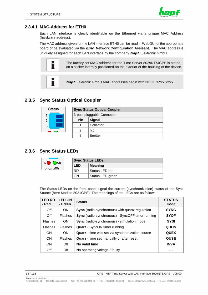
2.3.5 Sync Status Optical Coupler
Sync Status Optical Coupler
3-pole pluggable Connector
Pin Signal
1 Collector
2 n.c.
3 Emitter
2.3.6 Sync Status LEDs
Sync Status LEDs
LED Meaning
RD Status LED red
GN Status LED green
The Status LEDs on the front panel signal the current (synchronization) status of the Sync Source (here Module 8021GPS). The meanings of the LEDs are as follows:
LED RD - Red
LED GN - Green
Status STATUS
Code
Off ON Sync (radio-synchronous) with quartz regulation SYNC
Off Flashes Sync (radio-synchronous) - SyncOFF timer running SYOF
Flashes ON Sync (radio-synchronous) - simulation mode SYSI
Flashes Flashes Quarz - SyncON timer running QUON
ON ON Quarz - time was set via synchronization source QUEX
ON Flashes Quarz - time set manually or after reset QUSE
ON Off No valid time INVA
Off Off No operating voltage / faulty ---
SYSTEM STRUCTURE
GPS - NTP Time Server with LAN Interface 8029NTS/GPS - V05.00 15 / 118
This chapter describes the function principle of the Time Server 8029NTS/GPS and the internal relations between the different functional groups.
3.1 Block Diagram
Internal Supply Voltage
The individual functional components are supplied with the required operating voltage via the implemented power supply unit.
Firmware Update
A H8 firmware update of the Sync Souce (here Module 8021GPS) is completey controlled by Module 8029NTS. The update file for Module 8021GPS is loaded into Module 8029NTS via LAN through the WebGUI. Then Module 8029NTS performs the update of the Sync Source (here Module 8021GPS) independently.
Management
The entire control of the Sync Source (here Module 8021GPS) is done by Module 8029NTS. All data of the Sync Source, indicated via WebGUI, are demanded cyclically by Module 8029NTS from the Sync Source (here Module 8021GPS) or if necessary. These data are then prepared for the display in WebGUI. After activation settings for the Sync Source are transferred to the Sync Source immediately.
High Precision Time
The Sync Source provides a high-precision time information and the according synchronization status to Module 8029NTS. This time and status information is used for synchronization of the NTP service and if applicable other signal generations running on 8029NTS.
FUNCTION PRINCIPLE
GPS - NTP Time Server with LAN Interface 8029NTS/GPS - V05.00 17 / 118
The Module 8029NTS is the "heart" of the Time Server 8029NTS/GPS. A complete LINUX operating system is running on this Module providing all functions such as NTP, WebGUI etc. The Module also controls the connected Sync Source (here Module 8021GPS). Using the high-precise time information of Module 8021GPS the NTP service running on Module 8029NTS is also adjusted with high-precision. Thus the Module 8029NTS is a very precise NTP STRATUM 1 - Time Server.
3.3 Function 8021GPS (WebGUI: Sync Source)
The Module 8021GPS is in principle an independent Module with GPS receiver and its own µProcessor. In synchronous status it provides a high-precise time information to the Module 8029NTS. The control of Module 8021GPS in this system is completely done via Module 8029NTS. Parameters required by Module 8021GPS or provided are entered into WebGUI of Module 8029NTS or rather be output.
The Module 8021GPS has an own failsafe memory in which all required data for operation after generation via WebGUI are stored.
As the data of the Sync Source for the WebGUI indication need to be received by the Module 8029NTS at first, it is no real-time indication in WebGUI.
SYSTEM BEHAVIOUR
18 / 118 GPS - NTP Time Server with LAN Interface 8029NTS/GPS - V05.00
This chapter describes the behaviour of the system in special operational phases and conditions.
4.1 Boot Phase
The boot process of the Time Server 8029NTS/GPS starts after turning on the system or a reset.
During the boot process the Module 8029NTS boots its LINUX operation system and is therefore not available via LAN.
The end of the boot process is reached when the green NTP LED is shining and thereby indicates that the NTP service on Module 8029NTS has been started and enabled. The boot process lasts approx. 1-1.5 minutes.
4.2 NTP Adjustment Process (NTP/Stratum/Accuracy)
NTP is a regulation process. After start of the NTP services, automatically processed during booting, the Time Server 8029NTS/GPS requires approximately 5-10 minutes after synchronization of the Sync Source (Status "SYNC") until NTP is set to the high accuracy of the Sync Source (here Module 8021GPS) and reaches the optimized operation condition of STRATUM = 1 and ACCURACY = High.
The decisive factors here are accuracy of the synchronization source and the appropriate synchronization condition of the Sync Source.
4.3 Reset-(Default) Button
The Time Server 8029NTS/GPS can be reset by the Reset-(Default) Button behind the front panel of the board. The Reset-(Default) Button is accessible with a thin objective through the small drilling in the front panel.
The button triggers different functions depending on how long it is pressed:
Duration Function
< 1 sec. No action
1 - 9 sec. After releasing a systemwide hardware reset is triggered
10 - 19 sec. After releasing a CUSTOM DEFAULT followd by a REBOOT is triggered after approx. 10 seconds.
>= 20 sec. After releasing a FACTORY DEFAULT followd by a REBOOT is triggered after approx. 10 seconds
If the user saves no CUSTOM DEFAULT via the WebGUI, a FACTORY DEFAULT is triggered instead.
SYSTEM BEHAVIOUR
GPS - NTP Time Server with LAN Interface 8029NTS/GPS - V05.00 19 / 118
The Time Server 8029NTS/GPS is a multi processor system. For this reason a firmware update always consists of a so called Software SET including up to three (3) program releases defined by the SET version needed to be loaded into the board.
Module 8029NTS (WebGUI: Device):
1x Image Update
1x H8 Update (optional – not in the standard device)
Module 8021GPS (WebGUI: Sync Source):
1x H8 Update
An update is a critical process. The device should not be turned off during the update and the network connection to the device not be interrupted.
All programs of a SET needed to be uploaded to ensure a defined operation condition.
The progam releases assigned to a SET version may be taken from the release notes of the software SETs of the Time Sever 8029NTS/GPS.
4.4.1 Firmware Update 8029NTS (WebGUI: Device)
The general process of a software update of Module 8029NTS is described below:
H8 Update (Optional – only when in WebGUI available)
1. Log in as Master in WebGUI of the board.
2. Select in the Device tab the menu item H8 Firmware Update.
3. Select the file with the file extension .mot for Module 8029 via the selection window.
4. The selected file is shown in the selection window.
5. The update process is started with the button Upload now.
6. In WebGUI the successful file transfer to the Module is indicated.
7. Now the update of the board automatically starts after a few seconds.
8. After successful update the board automatically reboots.
9. After approx. 2 minutes the H8 update process is finished and the board is again accessible via WebGUI.
SYSTEM BEHAVIOUR
20 / 118 GPS - NTP Time Server with LAN Interface 8029NTS/GPS - V05.00
Currently the Time Server 8029NTS/GPS offers three functions that require an "Activation Key".
These functions are only available after entering a valid activation key related to the serial number of the Module 8029NTS (not the serial number of the overall system).
The activation of such function(s) can be done by default and also later by the user if required.
These functions are:
Alarming
After activation the functions SNMPv2, SNMPv3, Syslog and Email notification are available in order to monitor the system condition. Furthermore a MIB II and private enterprise MIB are provided with which management functions can be realized.
Routing
This function allows entering routes in the the Time Server 8029NTS/GPS for spezial network requirements.
SINEC H1 time datagram
This function allows paramerization of the SINEC H1 datagram and output via the LAN interface.
The settins for activation keys (e.g. an entered activation key) are neither modified nor influenced by the functions FACTORY DEFAULTS and CUSTOM DEFAULTS.
INSTALLATION
22 / 118 GPS - NTP Time Server with LAN Interface 8029NTS/GPS - V05.00
Grounding of the Time Server 8029NTS/GPS is achieved via the PE line of the power supply wiring.
5.3 Power Connection
Depending on the version of the appliance an AC or DC power feeding is available.
5.3.1 AC Power Supply
The standard AC power supply unit of the Time Server 8029NTS/GPS is described hereunder. However, the connection data on the nameplate of the respective device are always applicable.
Pay attention to the following when connecting the power supply:
Correct voltage type (AC or DC),
Voltage amount
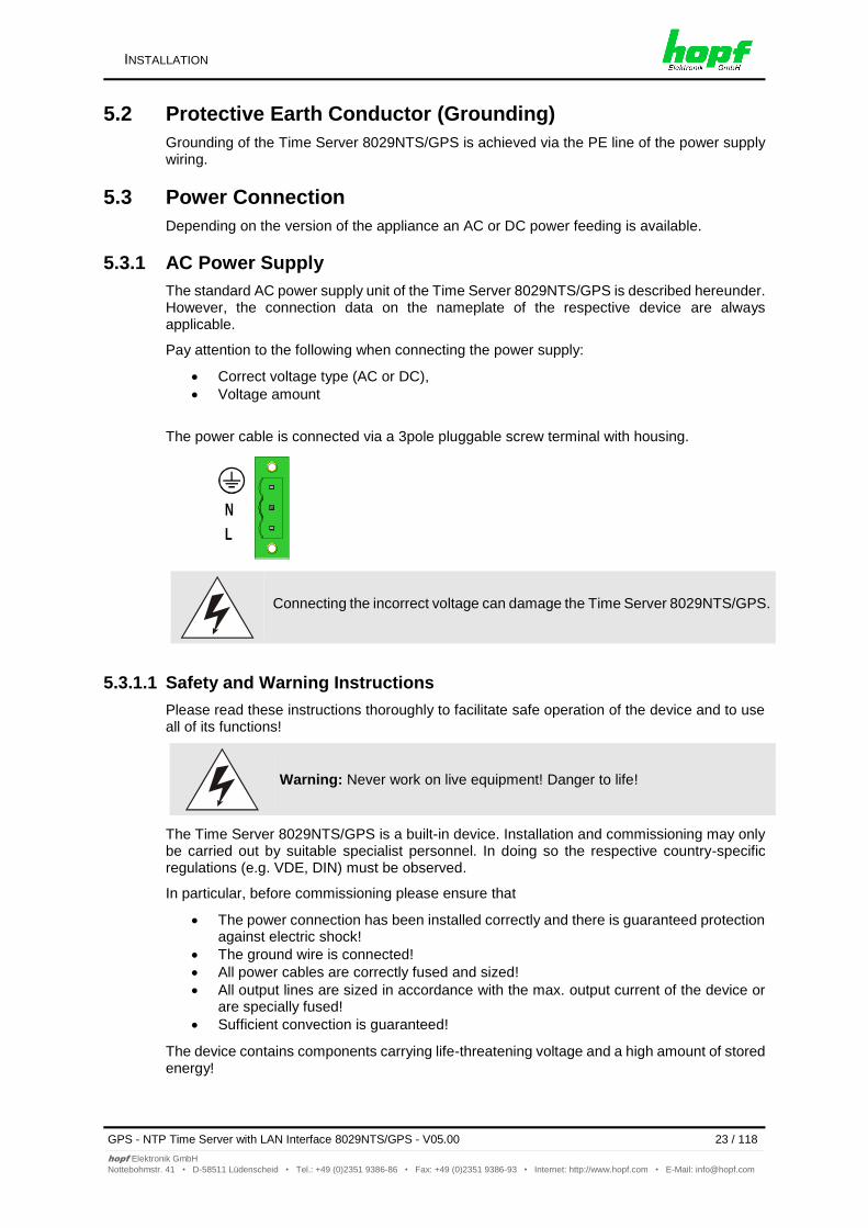
The power cable is connected via a 3pole pluggable screw terminal with housing.
N
L
Connecting the incorrect voltage can damage the Time Server 8029NTS/GPS.
5.3.1.1 Safety and Warning Instructions
Please read these instructions thoroughly to facilitate safe operation of the device and to use all of its functions!
Warning: Never work on live equipment! Danger to life!
The Time Server 8029NTS/GPS is a built-in device. Installation and commissioning may only be carried out by suitable specialist personnel. In doing so the respective country-specific regulations (e.g. VDE, DIN) must be observed.
In particular, before commissioning please ensure that
The power connection has been installed correctly and there is guaranteed protection against electric shock!
The ground wire is connected!
All power cables are correctly fused and sized!
All output lines are sized in accordance with the max. output current of the device or are specially fused!
Sufficient convection is guaranteed!
The device contains components carrying life-threatening voltage and a high amount of stored energy!
INSTALLATION
24 / 118 GPS - NTP Time Server with LAN Interface 8029NTS/GPS - V05.00
The 100-240V AC connection is made via the pluggable screw terminal L, N and .
Primary Side Fuse Protection
The device must be installed in accordance with the provisions of EN 60950. There must be a suitable isolating device external to the power supply capable of switching the device off.
The primary side line protection, for example, is suitable for this purpose.
Further equipment protection is not required because the device is fused internally.
Recommended External Fuse
When connecting the Time Server 8029NTS/GPS a suitable fuse protection of the power supply needs to be observed.
Accordingly, the performance data should be taken from the nameplate of the device. Currently the standard versions of the Time Server 8029NTS/GPS are supplied with power supplies with power consumption between 6 and 15VA.
Regarding DC applications a suitable fuse must be connected.
If the internal fuse trips it is highly likely that the device is faulty. In this case the equipment should be checked at the factory!
5.3.1.5 Power Supply Specifications
All specifications regarding the AC power supply can be found in Chapter 12.4 Power Supplies.
5.3.1.6 Power LED
The green Power LED allows a functional evaluation directly on site at the control cabinet.
LED lights Normal power supply operation
LED off No power supply is available or the device is faulty.
5.3.2 DC Power Supply
Make sure that the external voltage source is switched off. When connecting the power supply, ensure that the polarity and ground connection are correct!
The power supply cable is connected to the Time Server 8029NTS/GPS by means of a 2-pole plug connector with additional ground connection and interlock:
+Vin: Positive pole (contact 1)
–Vin: Negative pole (contact 2)
PE: Ground
INSTALLATION
26 / 118 GPS - NTP Time Server with LAN Interface 8029NTS/GPS - V05.00
Connecting the incorrect voltage can damage the Time Server 8029NTS/GPS.
Grounding: The negative pole (-Vin) and the ground (PE) are connected together as standard on the system side.
5.3.2.1 Power Supply Unit Specifications
All specifications regarding the DC power supply can be found in Chapter 12.4 Power Supplies.
5.3.2.2 Fuse Protection
When connecting the Time Server 8029NTS/GPS a suitable fuse protection of the power supply needs to be observed.
Accordingly, the performance data should be taken from the nameplate of the device. Currently the standard versions of the Time Server 8029NTS/GPS are supplied with power supplies with power consumption of max. 20VA.
If the internal fuse (device fuse) blows, it is most probable that the device is defective. In this case the device needs to be checked in the facatory!
5.4 Connection GPS Antenna System
The coaxial line of the GPS antenna system is placed on the BNC female connector with the "GPS Antenna" inscription on the front panel of the Time Server 8029NTS/GPS. More detailed descriptions referring to the installation of the antenna system, for example, cable lengths and cable types, are described in the document “Antenna System GPS”.
GPS Antenna
BNC Connector
GPS Antenna input
There is an antenna input monitoring for “open“ and “short-ciruit“ on the the system side.
INSTALLATION
GPS - NTP Time Server with LAN Interface 8029NTS/GPS - V05.00 27 / 118
This chapter describes commissioning of the Time Server 8029NTS/GPS.
6.1 General Procedure
Overview of the general commissioning procedure:
Finish the installation process completely
Switch on the device
Wait until the booting phase is finsihed (Duration approx. 2 min. – finished when the green NTP LED is lit on)
Using the SEARCH Function of the hmc - Network Configuration Assistant in order
to access the Time Server 8029NTS/GPS and set the basis LAN parameters (e.g. DHCP). Afterwards connect to the WebGUI of the Time Server 8029NTS/GPS via Web browser OR connect directly with the factory default IP-address (192.168.0.1) to the WebGUI of the Time Server 8029NTS/GPS via Web browser
Log in as "master"
Change default passwords for "master" and "device" In the DEVICE tab
Set all required LAN parameters (e.g. entry of DNS server) in NETWORK tab if necessary
Check current settings in NTP tab and modify according to individual needs as necessary
Parametrize following values of the Sync Source (here Module 8021GPS) in GPS SYNC SOURCE tab:
o Set current UTC time
o Set the local difference time to UTC
o Set or deactivate the changeover times for summer/winter time
o Set local position (if not known as 0)
o Check values for reception mode, SyncON/SyncOFF Timer and status OC
Trigger a Module Reset after the above mentioned entries
Check for Module Error in register GPS SYNC SOURCE
Parametrize optional functions e.g. SNMP or SINEC H1 time datagram
If all base settings are carried out correctly and there is GPS reception, the GENERAL tab should look like this after approx. 30 min.:
COMMISSIONING
GPS - NTP Time Server with LAN Interface 8029NTS/GPS - V05.00 29 / 118
The Time Server 8029NTS/GPS has no own switch for the power supply. The converter is activated by switching on the external power supply source.
6.3 Establish the Network Connection via Web Browser
Ensure that the network parameters of the Time Server 8029NTS/GPS are configured in accordance with the local network before connecting the device to the network.
Connecting a network to an incorrectly configured Time Server 8029NTS/GPS (e.g. duplicate IP address) may cause interference on the network.
The Time Server 8029NTS/GPS is supplied with a static IP-address (equivalent to the factory default setting). IP-address: 192.168.0.1 Network mask: 255.255.255.0 Gateway: not set
In case it is not known whether the Time Server 8029NTS/GPS with a Factory Default setting causes problems in the network, the basis network parameterization should be executed via a "Peer to Peer" network connection.
Request the required network parameters from your network administrator if those are unknown.
The network connection is made via a LAN cable and RJ45 plug (recommended cable type: CAT5 or better).
6.4 Network Configuration for ETH0 via LAN through hmc
After connecting the system to the power supply and creating the physical network connection to LAN interface of the Time Server 8029NTS/GPS, the device can be searched for on the
network via the hmc (hopf Management Console). Then the base LAN parameters (IP
address, netmask and gateway or DHCP) may be adjusted in order to allow accessibility of the Time Server 8029NTS/GPS for other systems on the network.
The SEACH Function of the hmc - Network Configuration Assistant
requires for location and recognition of the wished Time Server
8029NTS/GPS the hmc-computer in the same SUB Net.
COMMISSIONING
30 / 118 GPS - NTP Time Server with LAN Interface 8029NTS/GPS - V05.00
For an extended configuration of the Time Server 8029NTS/GPS through a browser via WebGUI the following base parameters are required:
Host Name e.g. hopf8029NTS
Network Configuration Type e.g. Static IP Address or DHCP
IP Address e.g. 192.168.100.149
Netmask e.g. 255.255.255.0
Gateway e.g. 192.168.100.1
The hostname must meet the following conditions:
The hostname may only contain the characters 'A'-'Z', '0'-'9', '-' and '.' . There should be no distinction between upper-and lower-case letters.
The character '.' may only appear as a separator between labels in domain names.
The sign '-' must not appear as first or last character of a label.
The network parameters being assigned should be pre-determined with the network administrator in order to avoid problems on the network (e.g. duplicate IP address).
IP Address (IPv4)
An IP address is a 32 bit value divided into four 8 bit numbers. The standard presentation is 4 decimal numbers (in the range 0...255) separated from each other by dots (dotted quad notation).
Example: 192.002.001.123
The IP address consists of a leading network ID followed by the host ID. Four common network classes were defined in order to cover different requirements. Depending on the network class, the last one, two or three bytes define the host while the rest define the network (network ID) in each case.
In the following text the "x" stands for the host part of the IP address.
Class A Networks
IP addresses 001.xxx.xxx.xxx to 127.xxx.xxx.xxx
There is a maximum of 127 different networks in this class. This allows the possibility to connect a very high number of devices (max. 16.777.216)
These network addresses are the most commonly used. Up to 254 devices can be connected.
Class D Networks
The addresses from 224.xxx.xxx.xxx - 239.xxx.xxx.xxx are used as multicast addresses.
Class E Networks
The addresses from 240.xxx.xxx.xxx - 254.xxx.xxx.xxx are designated as "Class E" and are reserved.
Gateway Address
The gateway or router address is required in order to be able to communicate with other network segments. The standard gateway must be set to the router address which connects these segments. This address must be within the local network.
After entering the above mentioned LAN parameters, they needed to be transferred to the Time Server 8029NTS/GPS via the Apply button. Afterwards the entry of the Device
Password is requested:
The Time Server 8029NTP/GPS is supplied with the default device password <device> on
delivery. After entry click on the OK button
to confirm. The LAN parameters thus set are directly adopted (without reboot) by the Time Server 8029NTS/GPS and are immediately active.
HTTP/HTTPS WEBGUI – WEB BROWSER CONFIGURATION INTERFACE
GPS - NTP Time Server with LAN Interface 8029NTS/GPS - V05.00 33 / 118
7 HTTP/HTTPS WebGUI – Web Browser Configuration Interface
For the correct display and function of the WebGUI, JavaScript and Cookies must be enabled in the browser.
The correct function & display of the WebGUI were verified on Windows XP and Windows7 using the browsers MS InternetExplorer 8 and Mozilla Firefox, version 6.0.2 and 14.0.1
7.1 Quick Configuration
This chapter gives a brief description of the basic operation of the WebGUI installed on the module.
7.1.1 Requirements
Ready-for-operation hopf NTP Time Server 8029NTS/GPS
PC with installed web browser (e.g. Internet Explorer) in the sub-network of Time Server 8029NTS/GPS
7.1.2 Configuration Steps
Create the connection to the Time Server with a web browser
Login as a 'master' user (default password <master> is set by delivery)
Switch to "Network" tab if available and enter the DNS Server (required for NTP and the alarm messages depending of network)
Save the configuration
Switch to "Device" tab and restart Network Time Server via "Reboot Device"
NTP Service is now available with the standard settings
NTP specified settings can be done in the "NTP" tab
Alarm messages via Syslog/SNMP/Email can be configured in "Alarm" tab – only if this function is enabled by an activation key
The following detailed explanatory information should be read if anything is unclear while executing the configuration steps.
HTTP/HTTPS WEBGUI – WEB BROWSER CONFIGURATION INTERFACE
34 / 118 GPS - NTP Time Server with LAN Interface 8029NTS/GPS - V05.00
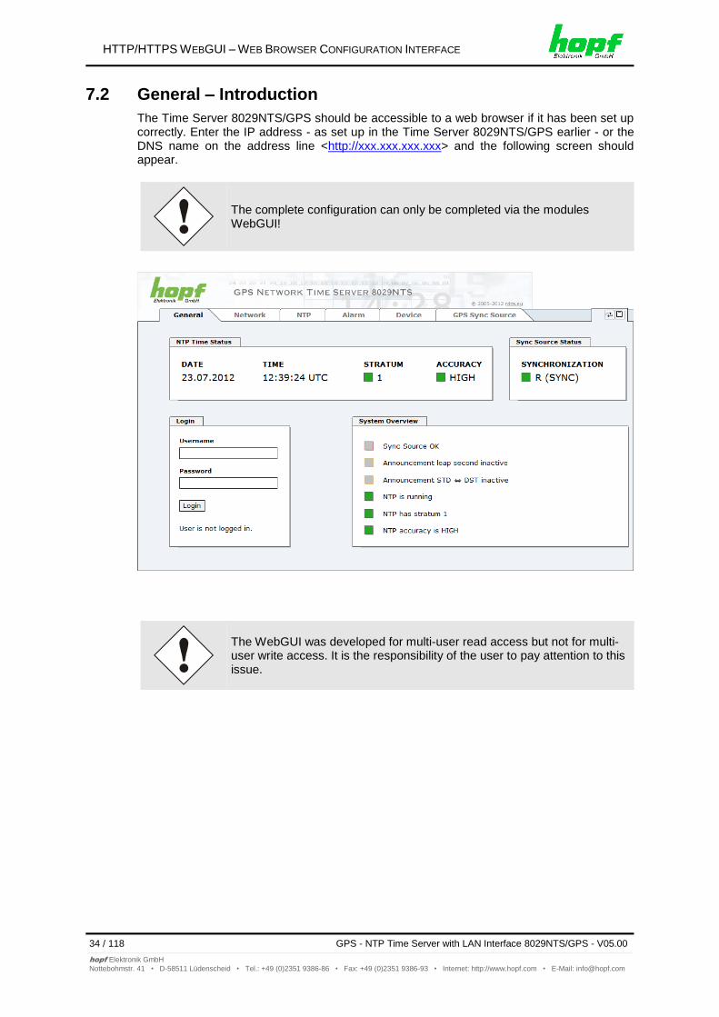
The Time Server 8029NTS/GPS should be accessible to a web browser if it has been set up correctly. Enter the IP address - as set up in the Time Server 8029NTS/GPS earlier - or the DNS name on the address line <http://xxx.xxx.xxx.xxx> and the following screen should appear.
The complete configuration can only be completed via the modules WebGUI!
The WebGUI was developed for multi-user read access but not for multi-user write access. It is the responsibility of the user to pay attention to this issue.
All of the modules data can be read without being logged on as a special user. However, the configuration and modification of settings and data can only be carried out by an authorised user! Two types of user are defined:
"master" user (default password on delivery: <master> )
"device" user (default password on delivery: <device> )
Differentiation is made between upper and lower case characters in the password. Alphanumeric characters and the following symbols can be used: [ ] ( ) * - _ ! $ % & / = ?
The password should be changed after the first login for security reasons.
The following screen should be visible after logging in as a "master" user:
Click on the Logout button to log out.
The WebGUI is equipped with a session management. If the user does not conduct a logout, the logout is automatically made after 10 minutes of inactivity (idle time).
HTTP/HTTPS WEBGUI – WEB BROWSER CONFIGURATION INTERFACE
36 / 118 GPS - NTP Time Server with LAN Interface 8029NTS/GPS - V05.00
After successful login, depending on the access level (device or master user), changes can be made to the configuration and saved.
Users logged in as "master" have all access rights to the Time Server 8029NTS/GPS.
Users logged in as "device" do not have access to:
Trigger reboot
Trigger factory defaults
Carry out image update
Carry out H8 firmware update
Upload certificate
Change master password
Download configuration files
7.2.2 Navigation via the Web Interface
The WebGUI is divided into functional tabs. Click on one of these tabs to navigate through the board. The selected tab is identified by a darker background colour, see the following image (General in this case).
User login is not required in order to navigate through the board configuration options.
JavaScript and Cookies should be enabled in the browser in order to guarantee the correct operation of the web interface.
All the links within the tabs on the left hand side lead to corresponding detailed display or setting options.
HTTP/HTTPS WEBGUI – WEB BROWSER CONFIGURATION INTERFACE
GPS - NTP Time Server with LAN Interface 8029NTS/GPS - V05.00 37 / 118
It is necessary to be logged on as one of the users described above in order to enter or change data.
7.2.3.1 Changing of Data in 8029NTS (WebGUI: Device)
All changeable data, except those in GPS SYNC SOURCE tab, are saved in Module 8029NTS. For these data the value saving is divided into two steps.
For a permanent saving the modified value MUST first be accepted with Apply from the module and then be stored with Save. Otherwise the modifications get lost after a reboot of the module or switching the system off.
After an entry with Apply is made, the configured field is marked with a star ' * '. This means that a value has been entered or changed but not yet been stored in the flash memory.
Meaning of the symbols from left to right:
No. Symbol Description
1 Apply Acceptance of changes and entered data
2 Reload Restoring the saved data
3 Save Fail-save storage of the data in the flash configuration
HTTP/HTTPS WEBGUI – WEB BROWSER CONFIGURATION INTERFACE
38 / 118 GPS - NTP Time Server with LAN Interface 8029NTS/GPS - V05.00
If the data should only be tested it is sufficient to accept the changes with Apply.
Changing Network Parameters
Modifications of the network parameters (e.g. IP address) are immediately effective clicking on Apply to confirm. However, the modifications are not permanently saved yet. This requires to access the WebGUI with the new network paramters again and to save the data with Save permanently.
For adopting changes and entering values only the respective buttons in the WebGUI can be used.
7.2.3.2 Changing of Data in 8021GPS (WebGUI: Sync Source)
The modified data in the GPS SYNC SOURCE tab are diretly transferred to the Module 8021GPS by pushing the button 1 and stored failsafe in Module 8021GPS. This can also be recognized by the modified display of the Apply button. The buttons 2 and 3 in GPS SYNC SOURCE tab are disabled and are not required.
The new reading of the modified data from Module 8029NTS for the WebGUI indication can take up to 30 seconds after data transfer to Module 8021GPS. However, this has no effect on the function of the appropriate setting/value.
HTTP/HTTPS WEBGUI – WEB BROWSER CONFIGURATION INTERFACE
GPS - NTP Time Server with LAN Interface 8029NTS/GPS - V05.00 39 / 118
A plausibility check is generally carried out during input.
As illustrated in the above image, an invalid value (e.g. text where a number should be entered, IP address not within the range etc.) is identified by a red border when an attempt is made to accept these settings. It should be noted here that this is only a semantic check and not to test whether an entered IP address can be used on the own network or in the configuration! As long as an error message is displayed it is not possible to save the configuration in the flash memory.
The error check only verifies semantics and the validity of ranges. It is NOT a logic or network check for entered data.
HTTP/HTTPS WEBGUI – WEB BROWSER CONFIGURATION INTERFACE
40 / 118 GPS - NTP Time Server with LAN Interface 8029NTS/GPS - V05.00
This is the first tab displayed when using the web interface.
NTP Time Status
This area shows basic information about the current time and date of the Time Server 8029NTS/GPS. The time always corresponds to UTC. The reason for this is that NTP always works with UTC and not with local time.
Stratum displays the actual NTP stratum value of the Time Server 8029NTS/GPS with the value range from 1-16.
The ACCURACY field (accuracy of NTP) can contain the values LOW - MEDIUM - HIGH. The meaning of these values is explained in Chapter 13.5 Accuracy & NTP Basic Principles.
HTTP/HTTPS WEBGUI – WEB BROWSER CONFIGURATION INTERFACE
GPS - NTP Time Server with LAN Interface 8029NTS/GPS - V05.00 41 / 118
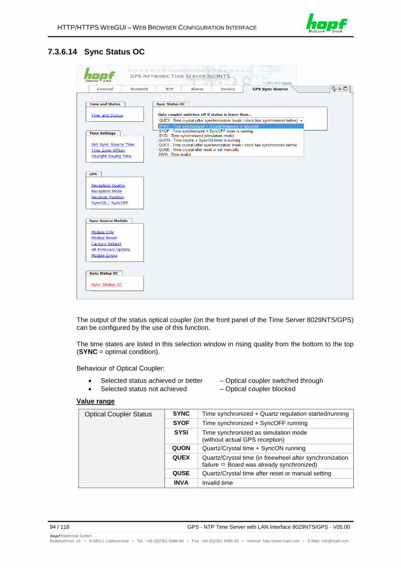
Display of the actual status of synchronization of the Sync Source (here Module 8021GPS) with these possible values:
SYNC Time synchronized + Quartz regulation started/running
SYOF Time synchronized + SyncOFF running
SYSI Time synchronized as simulation mode (without actual GPS reception)
QUON Quartz/Crystal time + SyncON running
QUEX Quartz/Crystal time (in freewheel after synchronization failure Board was already synchronized)
QUSE Quartz/Crystal time after reset or manual setting
INVA Invalid time
Login
The login box is described in Chapter 7.2.1 LOGIN and LOGOUT as User.
System Overview
This table gives a direct overview of the Time Server’s 8028NTS/GPS current operating states.
WebGUI Description
Sync Source OK When active (RED) there is a Sync Souce failure. For details please go to GPS SYNC SOURCE tab - Module Errors.
Announcement leap second inactive When active (ORANGE) there is an announcement for a leap-second.
Announcement STD DST inactive When active (ORANGE) there is an announcement for a summer / winter time change-over.
NTP is running The NTP process on Module 8029NTS is running
NTP has stratum 1 Shows the appropriate stratum the NTP process works with.
NTP Accuracy is High Shows the appropriate accuracy the NTP process works with.
Announcements
The display fields LEAP SECOND and STD DST announce a corrosponding event to the next hour (insertion of a leap-second or rather switchover of summer/winter time).
HTTP/HTTPS WEBGUI – WEB BROWSER CONFIGURATION INTERFACE
42 / 118 GPS - NTP Time Server with LAN Interface 8029NTS/GPS - V05.00
All the links within the tab on the left hand side lead to corresponding detailed setting options.
Changing Network Paramaters
Modifications of the network parameters (e.g. IP address) are immediately effective clicking on Apply to confirm. However, the modifications are not permanently saved yet. This requires to access the WebGUI with the new network paramters again and to save the data with Save permanently.
7.3.2.1 Host/Nameservice
Setting for the clear network detection.
7.3.2.1.1 Hostname
The standard setting for the Hostname is "hopf8029nts". This name should also be adapted to the respective network infrastructure.
If in doubt, simply leave the standard value in place or ask your network administrator.
The hostname must meet the following conditions:
The hostname may only contain the characters 'A'-'Z', '0'-'9', '-' and '.' . There should be no distinction between upper-and lower-case letters.
The character '.' may only appear as a separator between labels in domain names.
The sign '-' must not appear as first or last character of a label.
For a correct operation a hostname is required. The field for the hostname must not be left blank.
HTTP/HTTPS WEBGUI – WEB BROWSER CONFIGURATION INTERFACE
GPS - NTP Time Server with LAN Interface 8029NTS/GPS - V05.00 43 / 118
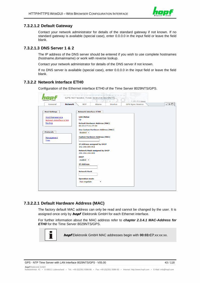
Contact your network administrator for details of the standard gateway if not known. If no standard gateway is available (special case), enter 0.0.0.0 in the input field or leave the field blank.
7.3.2.1.3 DNS Server 1 & 2
The IP address of the DNS server should be entered if you wish to use complete hostnames (hostname.domainname) or work with reverse lookup.
Contact your network administrator for details of the DNS server if not known.
If no DNS server is available (special case), enter 0.0.0.0 in the input field or leave the field blank.
7.3.2.2 Network Interface ETH0
Configuration of the Ethernet interface ETH0 of the Time Server 8029NTS/GPS.
7.3.2.2.1 Default Hardware Address (MAC)
The factory default MAC address can only be read and cannot be changed by the user. It is
assigned once only by hopf Elektronik GmbH for each Ethernet interface.
For further information about the MAC address refer to chapter 2.3.4.1 MAC-Address for ETH0 for the Time Server 8029NTS/GPS.
hopf Elektronik GmbH MAC addresses begin with 00:03:C7:xx:xx:xx.
HTTP/HTTPS WEBGUI – WEB BROWSER CONFIGURATION INTERFACE
44 / 118 GPS - NTP Time Server with LAN Interface 8029NTS/GPS - V05.00
The MAC address assigned from hopf can be changed to any user-defined MAC address.
The board identifies itself with the user-defined MAC address to the network. The default hardware address shown in WebGUI remains unchanged.
Double assignment of MAC addresses on the Ethernet referring to customers MAC addresses should be avoided. If the MAC address is not known, please contact your network administrator.
The use of customers MAC address needs to be activated by the function Use Custom Hardware Address (MAC) with enable.
The customers MAC address has to be entered in hexadecimal form with a colon to separateas described in the below example, e.g. 00:03:c7:55:55:02
The MAC address assigned by hopf can be activated at any time by
disabling this function.
There are no MAC multicast addresses allowed!
7.3.2.2.3 DHCP
If DHCP is to be used, activate this with enabled.
7.3.2.2.4 IP Address
If DHCP is not used, the IP address needed to be entered here. Contact your network administrator for details of the used IP address if not known.
7.3.2.2.5 Network Mask
If DHCP is not used, the network mask needed to be entered here. Contact your network administrator for details of the used network mask if not known.
7.3.2.2.6 Operation Mode
The network device usually adjusts the data stream and duplex mode to the device to which it is connected (e.g. HUB, SWITCH) automatically. If the network device requires a certain speed or duplex mode, this can be configured via the web interface. The value should only be changed in special cases. The automatic setting is normally used.
In individual cases an enabled "Auto negotiate" might lead to problems between the network components and the adjustment process fails.
In such cases it is recommended to set the network speed of the Time Server 8029NTS/GPS and the connected network components manually to the same value.
HTTP/HTTPS WEBGUI – WEB BROWSER CONFIGURATION INTERFACE
GPS - NTP Time Server with LAN Interface 8029NTS/GPS - V05.00 45 / 118
Protocols that are not required should be disabled for security reasons. A correctly configured module is always accessible via the web interface.
Changes to the availability of a protocol (enable/disable) take effect immediately.
For SNMP functionality an activation key is necessary.
If by mistake all protocol channels become "disabled", the SSH channel is automatically "enabled" after the attempt to save.
After a Factory Default the HTTP and SSH channels are "enabled".
These service settings are valid globally! Services with “disabled” status are not externally accessible and are not made externally available by the module!
HTTP/HTTPS WEBGUI – WEB BROWSER CONFIGURATION INTERFACE
GPS - NTP Time Server with LAN Interface 8029NTS/GPS - V05.00 47 / 118
7.3.2.5.2 SINEC H1 time datagram (Activation Key necessary)
Configuration of the SINEC H1 time datagram
Broadcast transmission intervals of the SINEC H1 time datagram (Send Interval):
every second
every 10 second
every 60 second
Timebase see also Chapter 13.2.1 Time-specific expressions:
Local time
UTC
Standard time
Standard time with daylight / standard time status
Destination MAC Address:
09:00:06:03:FF:EF
09:00:06:01:FF:EF
FF:FF:FF:FF:FF:FF
Synchronization Status based on Starting Transmission (Minimum Accuracy)
This setting defines at which internal accuracy status the SINEC H1 time datagram should be transmitted (see Chapter 13.5 Accuracy & NTP Basic Principles and Chapter 11 Technical Data):
LOW
MEDIUM
HIGH
The setting Minimum Accuracy = LOW may lead to the output of non-synchronised (thus possibly wrong) time information.
HTTP/HTTPS WEBGUI – WEB BROWSER CONFIGURATION INTERFACE
50 / 118 GPS - NTP Time Server with LAN Interface 8029NTS/GPS - V05.00
This tab shows information and adjustment possiblities of the NTP services of the Time Server 8029NTS/GPS. The NTP service is the significant main service of the Time Server 8029NTS/GPS.
If you are not familiar with the subject of NTP you can find a short description in the Glossary. More details are also available at http://www.ntp.org/.
NTP functionality is provided by an NTP-Demon running on the embedded Linux of the Time Server 8029NTS/GPS.
Depending on the receiving conditions and under unfavourable circumstances it may take several hours until long-term accuracy is obtained (normally 5-10 minutes). During this time the NTP algorithm adjusts the internal accuracy parameters.
The NTP time protocol must be enabled in order to use NTP (see Chapter 7.3.2.5 Time)
After all changes relating to NTP a restart of the NTP service must be performed (see Chapter 7.3.3.6 (Restart NTP)).
Via the NTP protocol SNTP Clients can also be synchronized. In contrast to NTP in SNTP Clients delay times are not evaluated on the network. For this reason the accuracy reached in SNTP Clients is lower than in NTP Clients.
7.3.3.1 System Info
In the window "System Info" the current NTP values of the NTP service running on the embedded Linux of the Time Server 8029NTS/GPS are indicated. In addition to the NTP calculated values for root delay, root dispersion, jitter, and stability the stratum value of the Time Server 8029NTS/GPS, the status to the leap second, and the current system peer are also found here.
The NTP version used adjusts the leap second correctly.
The Time Server 8029NTS/GPS works as NTP Server with stratum 1 and belongs to the best available class of NTP server, as it has a reference clock with direct access.
7.3.3.2 Kernel Info
The “Kernel Info” overview shows the current error values of the internal embedded Linux clock. Both values are internally updated every second.
This screenshot shows a maximum kernel clock error of 0.246 msec (milliseconds). The estimated error value is 5 μs (microseconds).
The values indicated here are based on the calculation of the NTP service and have no significance for the accuracy of the Sync Source (here Module 8021GPS).
HTTP/HTTPS WEBGUI – WEB BROWSER CONFIGURATION INTERFACE
52 / 118 GPS - NTP Time Server with LAN Interface 8029NTS/GPS - V05.00
The “Peers summary” is used to track the performance of the configured NTP server/driver and the NTP algorithm itself.
The information displayed is identical with the information available via NTPQ or NTPDC programes.
Each NTP server/driver that has been set up in the NTP server configuration is displayed in the peer information.
The connection status is displayed in the reachability column (not reachable, bad, medium, and reachable).
Three lines can be seen in the above image. The first line displays the hopf - refclock ntp
driver that gets the time information directly from the Sync Source.
The second and third line display external NTP server that can be additionally added to the
internal hopf – refclock ntp driver in the menu server configuration.
A short explanation and definition of the displayed values can be found in Chapter 13.5 Accuracy & NTP Basic Principles.
The character in the first column on the left presents the current status of the NTP association in the NTP selection algorithm. A list and description of possible characters can be found in the Glossary (see Chapter 13.2 Tally Codes (NTP-specific)).
HTTP/HTTPS WEBGUI – WEB BROWSER CONFIGURATION INTERFACE
GPS - NTP Time Server with LAN Interface 8029NTS/GPS - V05.00 53 / 118
As "Synchronization source" either GPS or DCF77, depending on the appropriate Sync Source, has to be selected. This is reuiqred in order to align the NTP algorithm for the calculation of the accuracy with the synchronization source.
Based on the selection of GPS, even though GPS is not the source of the Sync Source (different product option) the value HIGH for Accuracy may never be reached.
If the Sync Source (here Module 8021GPS) runs in crystal operation (status "crystal") the NTP service of the Time Server 8029NTS/GPS usually behaves in the way that the receipt of time information is stopped from the Sync Source and the stratum value reset to 16 (defined as invalid in NTP).
NTP Clients do not accept time information from a NTP Time Server with stratum 16 (invalid). Briefly, as long as the Time Server 8029NTS/GPS indicates the stratum value 16, NTP Clients are not synchronized.
This behaviour of NTP during crystal operation of the Sync Source can be changed. Therefore the function "Switch to specific stratum" should be enabled by setting the value to "enabled" and the so-called downgrading stratum (= stratum value of the Time Server 8029NTS/GPS during crystal operation of the Sync Source).
For the sychronization of NTP Clients during crystal operation of the Sync Source or for testing the system without connected synchronization source, in the setting "enabled" any stratum value between 1 and 15 can be set.
Crystal Operation / Stratum in Crystal Operation
The value defined here (range 1-15) designates the transmitted fallback NTP stratum level of the module in "Quartz" synchronization status. Stratum 1 should be configured if downgrading is not desired in status "Quartz".
The NTP service MUST also be restarted (see Chapter 7.3.3.6 Restart NTP).
Using the option "Switch to specific stratum" the NTP Clients are synchronized with time information indicated in the general menu of the WebGUI of the Sync Source (here Module 80121GPS) during crystal operating. Whether this time information (e.g. through drift) is imprecise or the time is manually set (wrong) cannot be detected by the NTP Client!
In case the value 1 is used for "Stratum in crystal operation", the NTP Client cannot not verify whether the Time Server 8029NTS/GPS is synchronised or runs in crystal operation. Should a differentiation be wished between synchronized and crystal operation the downgrading stratum needs to be set to a value between 2 and 15.
The value is only adjustable if the "Switch to specific stratum" function is enabled.
HTTP/HTTPS WEBGUI – WEB BROWSER CONFIGURATION INTERFACE
GPS - NTP Time Server with LAN Interface 8029NTS/GPS - V05.00 55 / 118
This section is used to configure the Time Server 8029NTS/GPS as a broadcast or multicast server.
The broadcast mode in NTPv3 and NTPv4 is limited to clients on the same sub-network and Ethernets which support broadcast technology.
This technology does not generally extend beyond the first hop (network node - such as router or gateway).
The broadcast mode is provided for configurations which are designed to facilitate one or more servers and as many clients as possible in a sub-network. The server continuously generates broadcast messages at defined intervals, corresponding to 16 seconds (minpoll 4) for Time Server 8029NTS/GPS. Care should be taken to ensure that the correct broadcast address is used for the sub-network, usually xxx.xxx.xxx.255 (e.g. 192.168.1.255). If the broadcast address is not known, this can be requested from the network administrator.
This section can also be used to configure the Time Server 8029NTS/GPS as a multicast server. The configuration of a multicast server is similar to that of a broadcast server. However, a multicast group address (class D) is used instead of the broadcast address.
An explanation of multicast technology goes beyond the scope of this document.
In principle, a host or router sends a message to an IPv4 multicast group address and expects all hosts and routers to receive this message. In doing so, there is no limit to the number of senders and receivers and a sender may also be a receiver and vice-versa. The IANA has assigned the multicast group address IPv4 224.0.1.1 to the NTP, however this should only be used if the multicast range can be safely limited in order to protect neighbouring networks. As a basic principle, administratively manageable IPv4 group addresses should be used as described in RFC-2365 or GLOP group addresses as described in RFC-2770.
7.3.3.4.5 Broadcast / Authentication / Key ID
Broadcast packets can be protected by authentication for security reasons.
If a security method is selected here, this must be configured additionally in the security settings of the NTP tab. A key must be defined if the Symmetric Key is selected.
7.3.3.4.6 Additional NTP SERVERS
Adding further NTP servers provides the opportunity to implement a security system for the time service. However, this affects the accuracy and stability of the Time Server 8029NTS/GPS.
Detailed information on this subject can be found in the NTP documentation (http://www.ntp.org/).
NTP is a standard for synchronising clocks in computer systems via packet-based communication networks. For special applications a NON standard setting can be configured.
For activation of this special NTP setting, the customer's approval shown in the WebGUI needed to be declared by checking the field "I agree".
7.3.3.5.1 Suppression of unspecified NTP Outputs (Block Output when Stratum Unspecified)
Unspecified NTP outputs that e.g. are generated by NTP at a restart are suppressed when this function is enabled.
HTTP/HTTPS WEBGUI – WEB BROWSER CONFIGURATION INTERFACE
GPS - NTP Time Server with LAN Interface 8029NTS/GPS - V05.00 57 / 118
For custom applications this function enables adjustment of the time base of the NTP output.
Entering this function the transmitted time protocol of the modul 8029NTC is not conform to the NTP standard anymore. According to the NTP standard NTP uses only the UTC time base. The NTP time protocol does not allow any leaps in time.
This function is only allowed for the Output of NTP In case of activated function the output of the module 8029NTS for SINEC H1 TIME DATAGRAM / TIME / DAYTIME is released with a wrong time basis. Therefore this datagram should be deactivated for security reasons.
Following configuration steps for the activation of the NTP time basis are required:
Select the wished NTP time base.
Transfer the setting with Apply Changes to the modul 8029NTC.
Fail-save storage of the configuration by pressing Save to Flash within 10 seconds. Depending on the activated time base leap a board reset might be released after transfer with Apply Changes eliminating non saved configurations.
UTC - NTP with Time Basis UTC
According to the RFC standard NTP uses only the UTC time base.
NTP with the Time Base Standard Time
Using the NTP time protocol with the standard time base the released time information correspond with UTC plus the time difference, adjusted in the base system without considering the daylight saving time changeover.
NTP with the Time Base Local Time
Output of the NTP time protocol with the local time base the released time information correspond with UTC plus the time difference and the additional offset for the possible summer time, adjusted in the base system.
NTP does not allow any leaps in time. Using the NTP time protocol with the local time base the internal NTP process of a board is restarted based on a summer-/winter time adjustment.
Using the NTP time protocol with the local time base the summer-/winter time adjustment is released one to two minutes belated.
Afterwards the local time is correctly available in the NTP time protocol. Therefore, within this transition period a requested NTP time protocol is replied by the former time base.
Changing the time base for the output of the protocol for NTP is only designed for customized applications and does not correspond with the standard of NTP. The synchronisation of a standard NTP-Client with a time basis deviating from UTC results in a wrong time information in the standard NTP-Client and might cause time leaps!
HTTP/HTTPS WEBGUI – WEB BROWSER CONFIGURATION INTERFACE
58 / 118 GPS - NTP Time Server with LAN Interface 8029NTS/GPS - V05.00
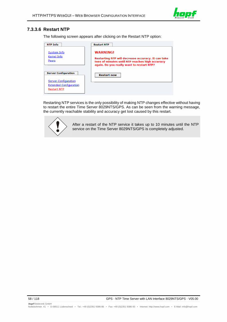
The following screen appears after clicking on the Restart NTP option:
Restarting NTP services is the only possibility of making NTP changes effective without having to restart the entire Time Server 8029NTS/GPS. As can be seen from the warning message, the currently reachable stability and accuracy get lost caused by this restart.
After a restart of the NTP service it takes up to 10 minutes until the NTP service on the Time Server 8029NTS/GPS is completely adjusted.
HTTP/HTTPS WEBGUI – WEB BROWSER CONFIGURATION INTERFACE
GPS - NTP Time Server with LAN Interface 8029NTS/GPS - V05.00 59 / 118
One of the extended configuration options for NTP is the "Access Restrictions" (NTP access restictions).
Restrictions are used in order to control access to the System’s NTP service and these are regrettably the most misunderstood options of the NTP configuration.
If you are not familiar with these options, a detailed explanation can be found at http://www.ntp.org/.
IP addresses should be used when configuring the restrictions – no Hostnames!
The following steps show how restrictions can be configured - should these not be required it is sufficient to retain the standard settings.
The standard restrictions tell the NTP service how to handle packets of hosts (including remote time servers) and sub-network which otherwise have no special restrictions.
The NTP configuration can simplify the selection of the correct standard restrictions while making the required security available.
Before beginning the configuration the points 7.3.3.7.1 to 7.3.3.7.4 must be checked by the user:
7.3.3.7.1 NAT or Firewall
Are incoming connections to the NTP Service blocked by NAT or a Stateful Inspection Firewall?
No Proceed to Chapter 7.3.3.7.2 Blocking Unauthorised Access
Yes No restrictions are required in this case. Proceed further to Chapter 7.3.3.7.4 Internal Client Protection / Local Network
Is it really necessary to block all connections from unauthorised hosts if the NTP Service is openly accessible?
No Proceed to Chapter 7.3.3.7.3 Allowing Client Requests
Yes
In this case the following restrictions are to be used:
ignore in the default restrictions
If a standard restriction is selected in this area, exceptions can be declared in separate lines for each authorised server, client or sub-network. See Chapter
7.3.3.7.5 Addition of Exceptions to Standard
7.3.3.7.3 Allowing Client Requests
Are clients to be allowed to see the server status information when they receive the time information from the NTP service (even if this is information about the module, operating system and NTPD version)?
No
In this case select from the following standard restrictions: See Chapter 7.3.3.7.6 Access Control Options
kod
notrap
nopeer
noquery.
Yes
In this case select from the following standard restrictions: See Chapter 7.3.3.7.6 Access Control Options:
kod
notrap
nopeer
If a standard restriction is selected in this area, exceptions can be declared in separate lines for each authorised server, client or sub-network. See Chapter
7.3.3.7.5 Addition of Exceptions to Standard .
7.3.3.7.4 Internal Client Protection / Local Network Threat Level
How much protection from internal network clients is required?
Yes
The following restrictions can be enabled if greater security settings than the installed authentication are required in order to protect the NTP service from the clients see Chapter 7.3.3.7.6 Access Control Options.
kod
notrap
nopeer
HTTP/HTTPS WEBGUI – WEB BROWSER CONFIGURATION INTERFACE
GPS - NTP Time Server with LAN Interface 8029NTS/GPS - V05.00 61 / 118
7.3.3.7.5 Addition of Exceptions to Standard Restrictions
After the standard restrictions have been set once, certain exceptions may be necessary for special hosts/sub-networks in order to allow remote time servers and client hosts/sub-networks to contact the NTP service.
These standard restrictions are to be added in the form of restriction lines.
An unrestricted access of the Time Server 8029NTS/GPS to its own NTP service is always allowed, irrespective of whether standard restrictions are ignored or not. This is necessary in order to be able to display NTP data on the web interface.
Add restriction exception: (for each remote time server)
Restrictions: Press ADD
Enter the IP address of the remote time server.
Enable restrictions: e.g.
notrap / nopeer / noquery
Allow unrestricted access to a special host (e.g. System administrator’s workstation):
Restrictions: Press ADD
IP address 192.168.1.101
Do not enable any restrictions
Allow a sub-network to receive time server and query server statistics:
Restrictions: Press ADD
IP address 192.168.1.0
Network mask 255.255.255.0
notrap / nopeer
HTTP/HTTPS WEBGUI – WEB BROWSER CONFIGURATION INTERFACE
62 / 118 GPS - NTP Time Server with LAN Interface 8029NTS/GPS - V05.00
The official documentation concerning the current implementation of the restriction instructions can be found on the “Access Control Options” page at http://www.ntp.org/.
Numerous access control options are used. The most important of these are described in detail here.
nomodify – "Do not allow this host/sub-network to modify the NTPD settings unless it has the correct key.“
Default Settings: Always active. Can't be modified by the user.
As standard, NTP requires authentication with a symmetric key in order to carry out modifications with NTPDC. If a symmetric key is not configured for the NTP service, or if this is kept in a safe place, it is not necessary to use the nomodify option unless the authentication procedure appears to be unsafe.
noserver – "Do not transmit time to this host/sub-network." This option is used if a host/sub-network is only allowed access to the NTP service in order to monitor or remotely configure the service.
notrust – "Ignore all NTP packets which are not encrypted.“ This option tells the NTP service that all NTP packets which are not encrypted should be ignored (it should be noted that this is a change from ntp-4.1.x). The notrust option MUST NOT be used unless NTP Crypto (e.g. symmetric key or Autokey) has been correctly configured on both sides of the NTP connection (e.g. NTP service and remote time server, NTP service and client).
noquery – "Do not allow this host/sub-network to request the NTP service status." The ntpd status request function, provided by ntpd/ntpdc, declassifies certain information over the running ntpd Base System (e.g. operating system version, ntpd version) which under certain circumstances ought not to be made known to others. It must be decided whether it is more important to hide this information or to give clients the possibility of seeing synchronization information over ntpd.
ignore – "In this case ALL packets are refused, including ntpq and ntpdc requests".
kod – "A kiss-o'-death (KoD) packet is transmitted if this option is enabled in the case of an access error." KoD packets are limited. They cannot be transmitted more frequently than once per second. Any KoD packet which occurs within one second from the last packet is removed.
notrap – "Denies support for the mode 6 control message trap service in order to synchronise hosts." The trap service is a sub-system of the ntpq control message protocols. This service logs remote events in programmes.
version – "Denies packets which do not correspond to the current NTP version."
Changes in data do not take effect immediately after clicking on the "Apply" symbol. The NTP service MUST also be restarted (see Chapter 7.3.3.6 Restart NTP ).
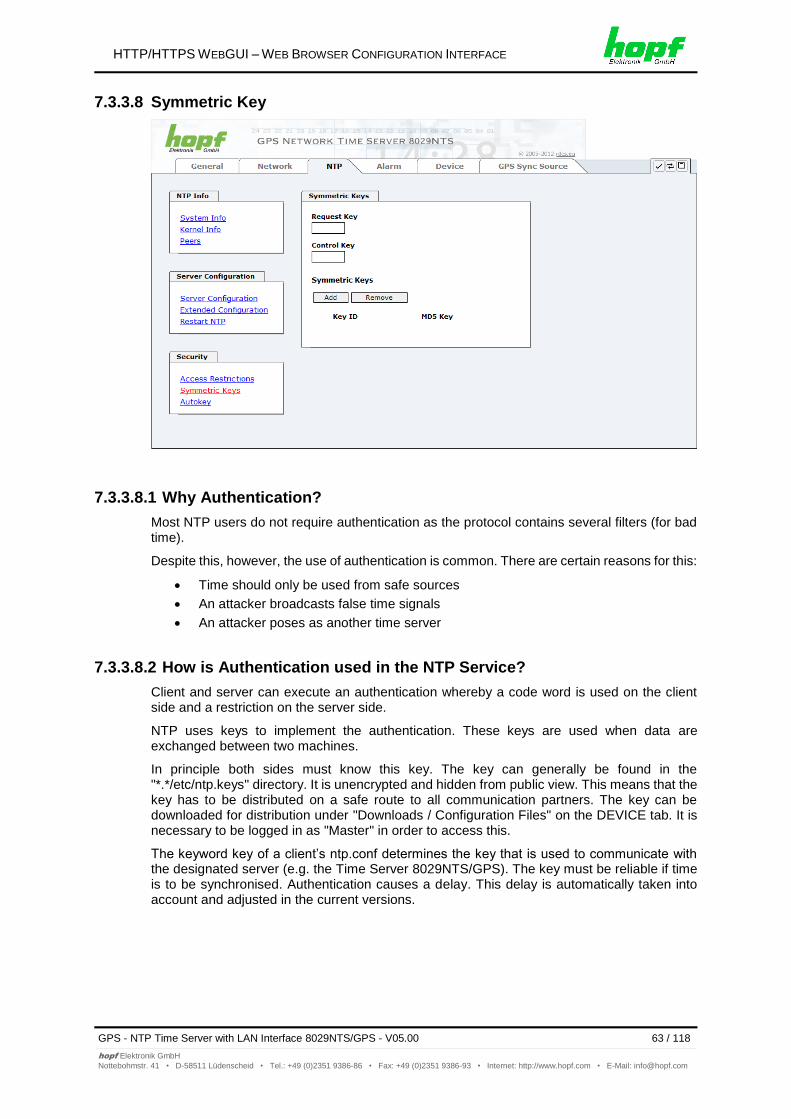
Most NTP users do not require authentication as the protocol contains several filters (for bad time).
Despite this, however, the use of authentication is common. There are certain reasons for this:
Time should only be used from safe sources
An attacker broadcasts false time signals
An attacker poses as another time server
7.3.3.8.2 How is Authentication used in the NTP Service?
Client and server can execute an authentication whereby a code word is used on the client side and a restriction on the server side.
NTP uses keys to implement the authentication. These keys are used when data are exchanged between two machines.
In principle both sides must know this key. The key can generally be found in the "*.*/etc/ntp.keys" directory. It is unencrypted and hidden from public view. This means that the key has to be distributed on a safe route to all communication partners. The key can be downloaded for distribution under "Downloads / Configuration Files" on the DEVICE tab. It is necessary to be logged in as "Master" in order to access this.
The keyword key of a client’s ntp.conf determines the key that is used to communicate with the designated server (e.g. the Time Server 8029NTS/GPS). The key must be reliable if time is to be synchronised. Authentication causes a delay. This delay is automatically taken into account and adjusted in the current versions.
HTTP/HTTPS WEBGUI – WEB BROWSER CONFIGURATION INTERFACE
64 / 118 GPS - NTP Time Server with LAN Interface 8029NTS/GPS - V05.00
A key is a sequence of up to 31 ASCII characters. Some characters with special significance cannot be used (alphanumeric characters and the following symbols can be used:[ ] ( ) * - _ ! $ % & / = ?).
A new line can be inserted by pressing the ADD key. The key which is stored in the key file
is entered on this line. The key ID is used to identify the key and is in the range from 1 – 65534. This means that 65534 different keys can be defined.
Duplicate key ID’s are not allowed. Having now explained the principles of keys, it should be possible to use a key in practically the same way as a password.
The value of the request key field is used as the password for the ntpdc tool while the value of the control key field is used as the password for the ntpq tool.
More information is available at http://www.ntp.org/.
7.3.3.8.4 How does authentication work?
The basic authentication is a digital signature and no data encryption (if there are any differences between the two). The data packet and the key are used to create a non-reversible number which is attached to the packet.
The receiver (which has the same key) carries out the same calculation and compares the results. Authentication has been successful if the results agree.
7.3.3.9 Autokey
NTPv4 offers a new Autokey scheme based on public key cryptography.
As a basic principle, public key cryptography is safer than symmetric key cryptography as protection is based on a private value which is generated by each host and is never visible.
In order to enable Autokey v2 authentication, the “Autokey Enabled” option must be set to "enabled" and a password specified (may not be blank).
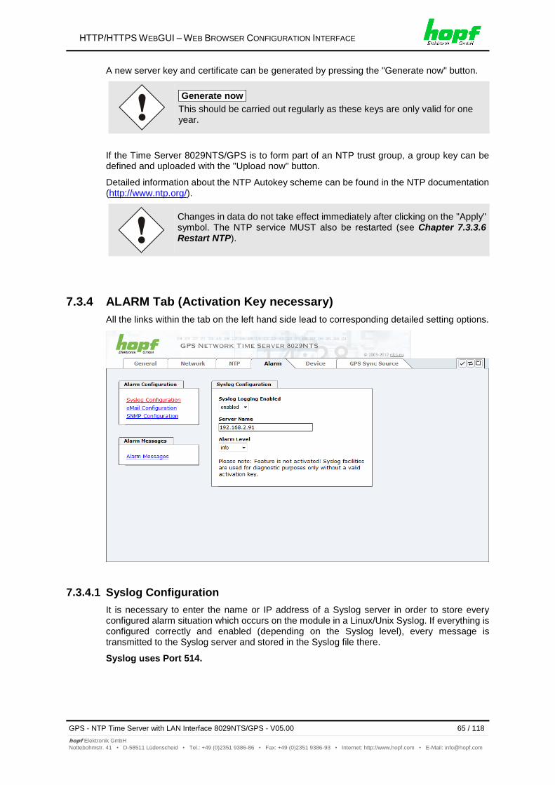
A new server key and certificate can be generated by pressing the "Generate now" button.
Generate now
This should be carried out regularly as these keys are only valid for one year.
If the Time Server 8029NTS/GPS is to form part of an NTP trust group, a group key can be defined and uploaded with the "Upload now" button.
Detailed information about the NTP Autokey scheme can be found in the NTP documentation (http://www.ntp.org/).
Changes in data do not take effect immediately after clicking on the "Apply" symbol. The NTP service MUST also be restarted (see Chapter 7.3.3.6 Restart NTP).
7.3.4 ALARM Tab (Activation Key necessary)
All the links within the tab on the left hand side lead to corresponding detailed setting options.
7.3.4.1 Syslog Configuration
It is necessary to enter the name or IP address of a Syslog server in order to store every configured alarm situation which occurs on the module in a Linux/Unix Syslog. If everything is configured correctly and enabled (depending on the Syslog level), every message is transmitted to the Syslog server and stored in the Syslog file there.
Co-logging in the system itself is not possible as therefore the internal memory is not of sufficient size.
It should be noted that the standard Linux/Unix Syslog mechanism is used for this functionality. This is not the same as the Windows System Event mechanism!
The alarm level designates the priority level of the messages to be transmitted and the level from which transmission should take place (see Chapter 7.3.4.4 Alarm Messages).
Alarm Level Transmitted Messages
none no messages
info info / warning / error / alarm
warning warning / error / alarm
error error / alarm
alarm alarm
The NTP service implemented in the system can transmit its own Syslog messages (see Chapter 7.3.3.4.2 NTP Syslog Messages (General / Log NTP Messages to Syslog)).
HTTP/HTTPS WEBGUI – WEB BROWSER CONFIGURATION INTERFACE
GPS - NTP Time Server with LAN Interface 8029NTS/GPS - V05.00 67 / 118
E-mail notification is one of the important features of this device which offers technical personnel the opportunity to monitor and/or control the IT environment.
It is possible to configure various, independing E-mail addresses which each have different alarm levels.
Dependending on the configured level, an E-mail is sent after an error has occurred on the respective receiver.
A valid E-mail server (SMTP server) must be entered for the purpose of correct configuration.
Some E-mail servers only accept messages if the sender address entered is valid (spam protection). This can be inserted in the “Sender Address” field.
The Alarm Level designates the priority level of the messages to be sent and determines from which level the message should be sent (see Chapter 7.3.4.4 Alarm Messages).
Alarm Level Transmitted Messages
none no messages
info info / warning / error / alarm
warning warning / error / alarm
error error / alarm
alarm alarm
HTTP/HTTPS WEBGUI – WEB BROWSER CONFIGURATION INTERFACE
68 / 118 GPS - NTP Time Server with LAN Interface 8029NTS/GPS - V05.00
It is possible to use an SNMP agent (with MIB) or to configure SNMP traps in order to monitor the module over SNMP.
SNMP traps are sent to the configured hosts over the network. It should be noted that these are based on UDP and therefore it is not certain that they will reach the configured host!
Several hosts can be configured. However, all have the same alarm level.
The private hopf enterprise MIB is also available over the web (see Chapter 7.3.5.11
Downloading Configuration Files / SNMP MIB).
The Alarm Level designates the priority level of the messages to be sent and determines from which level the message should be sent (see Chapter 7.3.4.4 Alarm Messages).
Alarm Level Transmitted Messages
none no messages
info info / warning / error / alarm
warning warning / error / alarm
error error / alarm
alarm alarm
The SNMP protocol must be enabled in order to use SNMP (see Chapter 7.3.2.4 Management (Management-Protocols – HTTP, SNMP etc.)).
HTTP/HTTPS WEBGUI – WEB BROWSER CONFIGURATION INTERFACE
GPS - NTP Time Server with LAN Interface 8029NTS/GPS - V05.00 69 / 118
Every message shown in the image can be configured with the displayed alarm levels. Selection of the level NONE means that this message is completely ignored.
Depending on the messages, their configured levels and notifications levels of the E-mails, a corresponding action is carried out if an event occurs.
Modified settings are failsafe stored after Apply and Save only.
HTTP/HTTPS WEBGUI – WEB BROWSER CONFIGURATION INTERFACE
70 / 118 GPS - NTP Time Server with LAN Interface 8029NTS/GPS - V05.00
All the links within the tab on the left hand side lead to corresponding detailed setting options.
This tab provides the basic information about the hardware of Module 8029NTS as well as software/firmware. Password administration and the update services for the module are also made accessible via this website. The complete download zone is also a component of this site.
7.3.5.1 Device Information
All information is available exclusively in write-protected and read-only form. Details on the board type, serial number and current software versions are provided to the user for service and enquiry purposes.
HTTP/HTTPS WEBGUI – WEB BROWSER CONFIGURATION INTERFACE
GPS - NTP Time Server with LAN Interface 8029NTS/GPS - V05.00 71 / 118
Read-only access is provided here in the same way as for device information.
The user requires this information in the case of service requests, e.g. MACH version, hardware status etc.
The display "Current DIP Switch Settings" is not applicable for this device.
7.3.5.3 Restoring the Factory Defaults Settings
In some cases it may be necessary or wished to reset all settings of module 8029NTS to factory settings (factory defaults).
This function serves to reset all values in the flash memory to their factory default values. This also includes passwords (see Chapter 12.1 Factory Default Values of Module 8029NTS (Device)).
HTTP/HTTPS WEBGUI – WEB BROWSER CONFIGURATION INTERFACE
72 / 118 GPS - NTP Time Server with LAN Interface 8029NTS/GPS - V05.00
Please log in as a “Master” user in accordance with the description in Chapter 7.2.1 LOGIN and LOGOUT as User
Pressing the "Reset now" button releases setting of the factory default values.
Once this procedure has been triggered there is NO possibility of restoring the deleted configuration.
A Factory Default requires a complete check and optionally a new configuration of the Module 8029NTS. In particulary the default MASTER and DEVICE passwords should be reset.
This function allows to save a current configuration as CUSTOM DEFAULTS.
The current configuration is saved. It is irrelevant whether the configuration has already been saved with "SAVE to FLASH" or just activated by "Apply".
In order to activate a CUSTOM DEFAULTS a configuration has to be saved initially.
Saving is only processed via the button "Save Custom Defaults now". A successful saving is confimred with a text message underneath the button.
If the user saves no CUSTOM DEFAULT via the WebGUI, a FACTORY DEFAULT via dthe Reset-(Default) button is triggered instead.
With this function the saved configuration is written back into the flash memory.
The settings for activation keys (e.g. an entered activation key) are neither deleted nor restored by the CUSTOM DEFAULTS.
HTTP/HTTPS WEBGUI – WEB BROWSER CONFIGURATION INTERFACE
GPS - NTP Time Server with LAN Interface 8029NTS/GPS - V05.00 73 / 118
The restart concerns the Module 8029NTS only but not the Sync Source (here Module 8021GPS).
All settings not saved with "Save" are lost on reboot (see Chapter 7.2.3 Enter or Changing Data).
Moreover the NTP service implemented in the system is restarted. This leads to a renewed alignment phase with the loss of the stability and accuracy reached up to this point.
Log in is carried out as “Master” user in accordance with the description in Chapter 7.2.1 LOGIN and LOGOUT as User.
Press the "Reboot now" button and wait until the restart has been perfomed.
7.3.5.6 Image Update for Module 8029NTS (WebGUI: Device)
Patches and Bug Fixes are provided for the individual boards by means of updates.
The embedded image is loaded only via the web interface in the Time Server 8029NTS/GPS (log in as “master” user required). See also Chapter 4.4 Firmware Update.
HTTP/HTTPS WEBGUI – WEB BROWSER CONFIGURATION INTERFACE
74 / 118 GPS - NTP Time Server with LAN Interface 8029NTS/GPS - V05.00
The following points should be considered regarding updates:
Only experienced users or trained technical personnel should carry out a board update after checking all necessary preconditions.
Important: Faulty updates or update attempts may, under certain circumstances, require the module to be returned to the factory for repair at customer’s expense.
Is the update on hand suitable for the module? If there are any
doubts please consult the support of the hopf company.
In order to guarantee a correct update, the "New version of saved site" function must be set to "On each access to the site" on the Internet browser used.
During the update procedure, the device must not be switched off not settings be saved to the flash memory!
Updates are always carried out as Software SETs. That means that all programmes included in the SET must be downloaded to the system.
For the update pay attention to point described in Chapter 4.4 Firmware Update
In order to carry out an update, enter the name and the folder in which the update / firmware image is located in the text field or open the file selection dialogue by pressing the "Browse" button.
A correct image designation is (e.g.):
upgrade_8029gen_v0120.img for the embedded image (update takes approx. 2-3 minutes)
The update process is started by pressing the "Update now" button. The update is installed if the transfer and checksum test are successful. A success page is displayed and shows the number of bytes that have been transferred and installed.
After the image-update the WebGUI displays a window to confirm the reboot of the Time Server 8029NTS/GPS.
HTTP/HTTPS WEBGUI – WEB BROWSER CONFIGURATION INTERFACE
GPS - NTP Time Server with LAN Interface 8029NTS/GPS - V05.00 75 / 118
Special security information displayed in the General tab can be entered here by the user.
The security information can be written as 'unformatted' text as well as in HTML format. There are 2000 characters available to write failsafe into the Time Server 8029NTS/GPS.
After a successful storage the "Customized Security Banner" with the saved security information is displayed in the General-Tab.
To delete the "Customized Security Banner" the inserted text must be deleted and saved again.
7.3.5.8 Product Activation
For the activation of optional functions, e.g "alarming" or "SINEC H1 time datagram", a special
activation key is required for which an order with the hopf Elektronik GmbH can be placed.
Each activation key is related to a special board with an appropriate serial number and cannot be used for several boards.
For a subsequent order of an activation key the serial number of the Module 8029NTS (device) needs to be provided. The serial number can be found under the tab DEVICE – Device info (serial number 8029…).
The settings for activation keys (e.g. an entered activation key) are neither deleted nor restored via the functions FACTORY DEFAULTS and CUSTOM DEFAULTS.
HTTP/HTTPS WEBGUI – WEB BROWSER CONFIGURATION INTERFACE
76 / 118 GPS - NTP Time Server with LAN Interface 8029NTS/GPS - V05.00
Full listening of all optional functions with the current activation status and stored activation key
Activate Feature
Input field to enter a new activation key. After entering the feature is activated by pressing the Apply button.
If the activation was successful the new feature is listed in the overview with status “Active” and can be used immediately.
Key Reset
Clears all activation keys and sets all optional features to status “Inactive”. All other non-optinal features are still available after peforming the key reset. If an optional feature is enabled again, the last stored configuration for this feature is restored.
HTTP/HTTPS WEBGUI – WEB BROWSER CONFIGURATION INTERFACE
GPS - NTP Time Server with LAN Interface 8029NTS/GPS - V05.00 77 / 118
It "status messages" is enabled the output is processed as SYSLOG message. This function
should only be used/enabled in case a problem arises and after consulting the hopf support.
7.3.5.10 Passwords (Master/Device)
Differentiation is made between upper and lower case characters in passwords. In principle, all alphanumeric characters and the following symbols are allowed in passwords:
[ ] ( ) * - _ ! $ % & / = ?
(See also Chapter 7.2.1 LOGIN and LOGOUT as User)
HTTP/HTTPS WEBGUI – WEB BROWSER CONFIGURATION INTERFACE
78 / 118 GPS - NTP Time Server with LAN Interface 8029NTS/GPS - V05.00
In order to be able to download certain configuration files via the web interface, it is necessary to be logged on as a "master" user.
The loaded file System Configuration from the module is only used for support purposes and cannot be reloaded for adjusting the settings in the Time Server 8029NTS/GPS.
For the download of the file System Configuration the following process is mandatory:
1. Pressing the button SAVE
2. Pressing the button Refresch System Configuration
3. Perform the download of the file
The "private hopf enterprise MIB" is also available via the WebGUI in this area.
HTTP/HTTPS WEBGUI – WEB BROWSER CONFIGURATION INTERFACE
GPS - NTP Time Server with LAN Interface 8029NTS/GPS - V05.00 79 / 118
The complete display and parameterization of the Sync Source (here Module 8021GPS) takes place in this tab.
The modified values in the tab GPS SYNC SOURCE are directly transferred to the Module 8021GPS (Sync Source) by pressing the button 1 and failsafe stored in Module 8021GPS. This behaviour is indicated on the modified display of the Apply button. The buttons 2 and 3 are without function in the tab GPS SYNC SOURCE and are not required.
After the data transfer to 8021GPS it can take up to 30 seconds until the modified data are re-read from 8029NTS for the WebGUI indication.
This delayed indication has no effect on the functionality.
Generally it is recommended to perform a restart of the the Sync Source (here Module 8021GPS) with a Module Reset after performing all modifications. This ensures that the Module 8021GPS will be operated with the new and failsafe stored data.
7.3.6.1 Time and Status
HTTP/HTTPS WEBGUI – WEB BROWSER CONFIGURATION INTERFACE
80 / 118 GPS - NTP Time Server with LAN Interface 8029NTS/GPS - V05.00
This area indicates the curent time and date of the Sync Source. Both the local and UTC time are displayed.
In theory, depending on the synchronization status of the Sync Source, the time displayed here can differ from the NTP time since two independent time systems are involved.
Announcements
The display fields LEAP SECOND and STD DST announce a corrosponding event to the next hour (insertion of a leap-second or rather switch-over of summer/winter time).
Sync Source Status
Display of the actual status of synchronization of the Sync Source with these possible values:
SYNC Time synchronized + Quartz regulation started/running
SYOF Time synchronized + SyncOFF running
SYSI Time synchronized as simulation mode (without actual GPS reception)
QUON Quartz/Crystal time + SyncON running
QUEX Quartz/Crystal time (in freewheel after synchronization failure Board was already synchronized)
QUSE Quartz/Crystal time after reset or manual setting
INVA Invalid time
7.3.6.2 Set Sync Source Time
Adjustment of UTC including the date in the Sync Source (here Module 8021GPS)
After entering the plausibility of these values are directly checked by clicking on the Apply button and then sent to the Sync Source (here Module 8021GPS).
Always the UTC time must be set. The local time is internally calculated from the difference time (Time Zone Offset) and the summer / winter time changeover (Daylight Saving Time).
HTTP/HTTPS WEBGUI – WEB BROWSER CONFIGURATION INTERFACE
GPS - NTP Time Server with LAN Interface 8029NTS/GPS - V05.00 81 / 118
The input must be complete and according to the stated format.
7.3.6.3 Time Zone Offset
Setting of the difference time (Time Zone Offset) from UTC to the local standard time (winter time) in the Sync Source (here Module 8021GPS)
The difference time to be entered always relates to the local standard time (winter time) even though the commissioning or rather the input of the difference time takes place during daylight saving time.
Offset Hours Time Zone Offset input of the full hour (0-13)
Offset Minutes Time Zone Offset input of minutes (0-59)
Example:
Time Offset for Germany East, 1 hour and 0 minutes (+ 01:00)
Time Offset for Peru West, 5 hours and 0 minutes (- 05:00)
Direction relating to Prime Meridian – Direction of the Difference Ttime
Entering the direction the local time deviates from world time:
'East' corresponds to east,
'West' corresponds to west of the Prime-Meridian (Greenwich)
HTTP/HTTPS WEBGUI – WEB BROWSER CONFIGURATION INTERFACE
82 / 118 GPS - NTP Time Server with LAN Interface 8029NTS/GPS - V05.00
Setting of the changeover times for summer/winter time in the Sync Source (here Module 8021GPS).
This input is used to define the point of time at which the changeover to Daylight Saving Time or winter time occurs during the course of the year. The hour, day of the week, week of the month and month at which the the Daylight Saving Time begins and ends are determined.
So the exact times are automatically calculated for the running year.
After the turn of the year the changeover times for summer/winter time are automatically recalculated, without any user intervention.
DST Activation (enabled/disabled) – Changeover times for summer/winter time
DST Begin – Changeover time for standard time to Daylight Saving Time
DST End – Changeover time for Daylight Saving Time to standard time
The individual items have the following meanings:
Week How often the changeover should be processed per day of the week in the month
First - 1st week
Second - 2nd week
Third - 3th week
Fourth - 4th week
Last - last week
Day The day of the week when the changeover should be processed
Sunday, Monday … Saturday
Month the month when the changeover should be processed
January, February ... December
Hour Minute
The time in hour and minute when the changeover should be processed
00h ... 23h 00min ... 59min
The data are entered on the basis of the local time.
HTTP/HTTPS WEBGUI – WEB BROWSER CONFIGURATION INTERFACE
GPS - NTP Time Server with LAN Interface 8029NTS/GPS - V05.00 83 / 118
In this tab the GPS reception mode is adjusted and displayed.
3D - Evaluation
The accuracy of the time evaluation is defined by the exact position calculation of the installation site. For this calculation (3D evaluation) it is necessary to receive information from at least four (4) satellites. The signal runtime to several satellites is determined from the calculated position and the precise second mark is generated from their mean value.
Position-fix - Evaluation
In position-fix mode the system can be synchronized using the data from only one received satellite. The system accuracy is depending on the exactness of the entered position of the installation site. The second mark is calculated for the set position. If four or more satellites are received in the position-of mode, the evaluation switches automatically into 3D mode and calculates the exact position. In this case, the accuracy of the position-fix evaluation increases to the same accuracy as in 3D evaluation.
HTTP/HTTPS WEBGUI – WEB BROWSER CONFIGURATION INTERFACE
GPS - NTP Time Server with LAN Interface 8029NTS/GPS - V05.00 85 / 118
In this tab the current postion is adjusted and displayed.
Longitude / Latitude – Current Position with Longitude and Latitude
Hereby the geographical position of the system is entered. This is a helpful function referring to the initial commissioning of the system and reduces the first synchronization time of the GPS receiver.
For an acceleration of the synchronization of the GPS receiver it is only required to adjust the position exactly to 1-2 degrees (without minutes and decimal expansions).
If the position is unknown, enter 0 for all numbers and North and East for the direction.
Relating to a manual input the last numbers (milliseconds) of the position are always 00000. After a succesful synchronization of the Clock System there should at least in one of the two lines the numbers 00000 be replaced by the complete position calculated by the GPS receiver.
HTTP/HTTPS WEBGUI – WEB BROWSER CONFIGURATION INTERFACE
86 / 118 GPS - NTP Time Server with LAN Interface 8029NTS/GPS - V05.00
The SyncON timer is used to delay the sync-status “SYNC” by the set time although the GPS receiver is synchronous.
This function is enabled when adjustment processes should be terminated as defined before the sync status is “SYNC”.
This function is not required for this device and should always be set to 0.
SyncOFF Timer
This value is used to provide reception failure bypassing for an error-message free operation even under poor reception conditions.
In the event of a reception failure of the Sync Soure (here Module 8021GPS), the re-synchronization of the Sync Source to quartz status is delayed by the set value. The system continues to run in synchronization status on the internally regulated, highly accurate quartz base during this period.
This timer is of special significance when certain system outputs are linked to a specific system status.
The Timer can be set from 2min. to 1440min.
Current Timer values
In case of an active Timer the appropriate value of the timer is displayed here.
HTTP/HTTPS WEBGUI – WEB BROWSER CONFIGURATION INTERFACE
GPS - NTP Time Server with LAN Interface 8029NTS/GPS - V05.00 87 / 118
After setting the Sync Source to factory default values the GPS receiver needs up to 13 minutes of satellite reception in order to generate the correct information on the leap second from the GPS data. Only then the Sync Source (here Module 8021GPS) can be synchronized.
During this time (however only when the GPS receiver really receives satellites) the following message is displayed in the tab Module Errors:
GPS Receiver in raw data mode - no sychronisation
If the changeover times for summer/winter time and the difference time are not initial set after a factory default of the Sync Source (here Module 8021GPS) the following message is displayed in the tab Module Errors:
Missing data for Time Zone Offset
and/or
Missing or incomplete data for daylight saving time (DST)
HTTP/HTTPS WEBGUI – WEB BROWSER CONFIGURATION INTERFACE
90 / 118 GPS - NTP Time Server with LAN Interface 8029NTS/GPS - V05.00
Patches and Bug Fixes are provided for the Time Server 8029NTS/GPS by means of updates.
The H8 update of the Sync Source is loaded only via the web interface in the Time Server 8029NTS/GPS (log in as “master” user required). See also Chapter 4.4 Firmware Update.
The following points should be considered regarding updates:
Only experienced users or trained technical personnel should carry out a board update after checking all necessary preconditions.
Important: Faulty updates or update attempts may, under certain circumstances, require the module to be returned to the factory for repair at customer’s expense.
Is the the update on hand suitable for the module? If there are any
doubts please consult the support of the hopf company.
In order to guarantee a correct update, the "New version of saved site" function must be set to "On each access to the site" on the Internet browser used.
During the update procedure, the device must not be switched off not settings be saved to the flash memory!
Updates are always carried out as Software SETs. That means that all programmes included in the SET must be downloaded to the system.
For the update pay attention to point described in Chapter 4.4 Firmware Update
In order to carry out an update, enter the name and the folder in which the update / firmware image is located in the text field or open the file selection dialogue by pressing the "Browse" button.
HTTP/HTTPS WEBGUI – WEB BROWSER CONFIGURATION INTERFACE
GPS - NTP Time Server with LAN Interface 8029NTS/GPS - V05.00 91 / 118
Missing or incomplete data for daylight saving time (DST)
The switchover times for summer/winter time must be initially set / disabled by the user.
Otherwise there is no synchronization of the Sync Source (here Module 8021GPS).
SPIO setting error
If this error occurs even after a voltage reset, the support team of company hopf
needs to be contacted for further actions.
Overview Hardware Errors
Adjustment of internal quartz frequency error
Problems with the internal quartz regulation of the Sync Source (here Module 8021GPS) have occured. So the specified accuracy of the Sync Source cannot be guaranteed anymore.
Antenna circuit shorted
The Sync Source (here Module 8021GPS) has detected a short circuit in the antenna system. The antenna system should be checked.
Antenna circuit open
The Sync Source (here Module 8021GPS) has detected an open antenna input. The antenna system should be checked.
FRAM error
If this error occurs even after a voltage reset, the support team of company hopf
needs to be contacted for further actions.
RTC error
If this error occurs even after a Power down, the internal backup clock is damaged. So there is no valid time information available after switching on the device or after a reset of the Sync Source.
GPS receiver communication error
If this error occurs even after a Power down, the support team of company hopf needs
to be contacted for further actions.
GPS receiver in raw data mode – no synchronization
If this condition is indicated, the GPS receiver requires special data from the GPS signal for which it needs up to 13 minutes signal receiption of satellites. Only then the Sync Source (here Module 8021GPS) can be synchronized.
This happens e.g. after resetting the Sync Source paramaters to factory default values.
HTTP/HTTPS WEBGUI – WEB BROWSER CONFIGURATION INTERFACE
94 / 118 GPS - NTP Time Server with LAN Interface 8029NTS/GPS - V05.00
Only basic configuration is possible via SSH or Telnet. The complete configuration of the Time Server 8029NTS/GPS takes place exclusively via the WebGUI.
It is just as easy to use SSH (Port 22) or Telnet (Port 23) as the WebGUI. Both protocols use the same user interface and menu structure.
The user names and passwords are the same as on the WebGUI and are kept in alignment (see Chapter 7.3.5.10 Passwords (Master/Device)).
SSH does not allow blank passwords for safety reasons.
The corresponding protocols should be enabled for the use of Telnet or SSH (see Chapter 7.3.2.4 Management (Management-Protocols – HTTP, SNMP etc.)).
The navigation through the menu takes place by entering the respective number associated with the menu option (as can be seen in the above image).
FAULT ANALYSIS / TROUBLESHOOTING
96 / 118 GPS - NTP Time Server with LAN Interface 8029NTS/GPS - V05.00
This chapter explains different error patterns and the process to contact the hopf support
team.
9.1 Error Patterns
This chapter describes various error patterns which enable the customer to make a preliminary problem analysis. In addition they also provide assistance in describing the error when
contacting the hopf support.
If possible, for each problem the entire status in the tabs GENERAL and GPS SYNC SOURCE page "Module Errors" via WebGUI should always be checked.
9.1.1 Complete Failure
Description
The Status LEDs on the front panel are off
Cause / Problem Solution
Device is switched off
Voltage supply failure
Power supply defective
9.1.2 No GPS Reception / No Synchronization
Description
In WebGUI the status of the SYNC SOURCE is not displayed with SYNC or SYOF
The Status LEDs of Module 8021GPS on the front panel do not indicate SYNC or SYOF status
Cause / Problem Solution
System was not correctly/completely initialized
The following describes various effects and their possible causes on a non-synchronizing system:
FAULT ANALYSIS / TROUBLESHOOTING
GPS - NTP Time Server with LAN Interface 8029NTS/GPS - V05.00 97 / 118
Effect: After the first installation, no satellite appears on the display after several hours and 00 is displayed under Satellites in View.
Possible Errors:
The antenna cable is too long
An incorrect cable type was used for the length of the antenna equipment
The antenna cable is faulty
The antenna cable is not connected
The antenna is defective
The indirect lightning protection is defective
Case 2:
Effect: There are 7 satellites in the visibility range (V=07) but a maximum of 2 appear on the display frame. However, the value of these satellites is 70 or above.
Possible Errors:
The visibility range of the antenna to the sky is limited and the Module 8021GPS set to 3D reception mode.
Case 3:
Effect: There are 9 satellites in the visibility range (V=09) and 6 appear on the display frame. The signal/noise ratios are all below 30. The equipment is not synchronized.
Possible Errors:
The cable is too long
An incorrect cable type was used for the length of the antenna equipment
The BNC connectors are poorly mounted
The cable is bent or crimped
Indirect lightning protection was irreversibly damaged by overvoltage
The antenna is defective
Case 4:
Effect: The equipment was working perfectly but has not been receiving for several days. 7 satellites appear in the visibility range (V=07) but no satellite is displayed.
Possible Errors:
The cable has been damaged
There was excess voltage on the antenna equipment and the indirect lightning protector is defective
The antenna is defective
The GPS receiver of Module 8021GPS is defective
A building change has had an effect on the antenna equipment (e.g. shading of the antenna caused by subsequent building installation, or the laying of cables with a high electrical alternating field in the immediate vicinity of the GPS antenna cable)
Electronic equipment with an interference effect on the GPS signal has been put into operation in the vicinity of the GPS antenna equipment / GPS receiver (e.g. transmitter for pagers)
Further information on the subject of the GPS antenna system can be consulted in the manual "Antenna Equipment GPS".
FAULT ANALYSIS / TROUBLESHOOTING
98 / 118 GPS - NTP Time Server with LAN Interface 8029NTS/GPS - V05.00
Providing a detailed error description and above listed information avoid the need for additional clarification and leads to a faster processing by the support team.
The Time Server 8029NTS/GPS is generally maintenance-free. The following points should be observed if a cleaning of the system might be necessary.
10.1 General Guidelines for Cleaning
The following must not be used to clean the Time Server 8029NTS/GPS:
Fluids
Cleaning agents containing solvents
Cleaning agents containing acids
Abrasive media
The use of such cleaning agents or media could damage the Time Server 8029NTS/GPS.
Do not use a wet cloth to clean the Time Server 8029NTS/GPS. There is the danger of an electric shock.
To clean the Time Server 8029NTS/GPS use a cloth that is:
Antistatic
Soft
Non-fabric
Damp
10.2 Cleaning the Housing
Make sure that connections or cables are not loosened while cleaning the housing of the Time Server 8029NTS/GPS. There is the danger of damage and functionality loss.
TECHNICAL DATA
100 / 118 GPS - NTP Time Server with LAN Interface 8029NTS/GPS - V05.00
This chapter lists the factory default values of the individual components integrated in the Time Server 8029NTS/GPS.
12.1 Factory Default Values of Module 8029NTS (Device)
The default delivery status of the Time Server 8029NTS/GPS meets the factory default values when using GPS synchronization sources. In case of DCF77 synchronization (different product variant) the function "NTP / General / Sync Source" is factrory-set to "DCF77" on delivery.
Using the board in DCF77 sytems (different product variant) the setting for NTP / General / Sync Source" needs to be re-configured to "DCF77" after a factory default.
NTP Server Configuration Setting WebGUI
Sync Source DCF77 DCF77
12.1.1 Network
Host/Name Service Setting WebGUI
Hostname hopf8029nts hopf8029nts
Default Gateway Blank ---
DNS 1 Blank ---
DNS 2 Blank ---
Network Interface ETH0 Setting WebGUI
Use Custom Hardware Address (MAC) Disabled Disabled
Custom Hardware Address (MAC) Blank ---
DHCP Disbabled Disabled
IP 192.168.0.1 192.168.0.1
Netmask 255.255.255.0 255.255.255.0
Operation mode Auto negotiate Auto negotiate
Routing Setting WebGUI
User Defined Routes Blank ---
Management Setting WebGUI
HTTP Enabled Enabled
HTTPS Disabled Disabled
SSH Enabled Enabled
TELNET Disabled Disabled
SNMP Disabled Disabled
System Location Blank ---
System Contact Blank ---
Read Only Community Blank ---
Read/Write Community Blank ---
Security Name Blank ---
Access Rights Readonly Readonly
Authentication Protocol MD5 MD5
Authentication Passphrase Blank ---
Privacy Protocol DES DES
Privacy Passphrase Blank ---
FACTORY DEFAULTS OF TIME SERVER 8029NTS/GPS
GPS - NTP Time Server with LAN Interface 8029NTS/GPS - V05.00 107 / 118
Stability The average frequency stability of the clock system.
Accuracy Specifies the accuracy in comparison to other clocks.
Precision of a clock
Specifies how precisely the stability and accuracy of a clock system can be maintained.
Offset This value represents the time difference between two clocks. It is the offset by which the local time would have to be adjusted in order to keep it congruent with the reference clock.
Clock skew The frequency difference between two clocks (first derivative of offset over time).
Drift Real clocks vary in frequency difference (second derivative of offset over time). This variation is known as drift.
Roundtrip delay Roundtrip delay of an NTP message to the reference and back.
Dispersion Represents the maximum error of the local clock relative to the reference clock.
Jitter The estimated time error of the system clock measured as the average exponential value of the time offset.
13.2 Tally Codes (NTP-specific)
space reject Rejected peer – either the peer is not reachable or its synchronization distance is too great.
x falsetick The peer was picked out by the NTP intersection algorithm as a false time supplier.
. excess The peer was picked out by the NTP sort algorithm as a weak time supplier on the basis of synchronization distance (concerns the first 10 peers).
- outlyer The peer was picked out by the NTP clustering algorithm as an outlyer.
+ candidate The peer was selected as a candidate for the NTP combining algorithm.
# selected The peer is of good quality but not among the first six peers selected by the sort algorithm on the basis of synchronization distance.
* sys.peer The peer was selected as a system peer. Its characteristics are transferred to the Base System.
o pps.peer The peer was selected as a system peer. Its characteristics are transferred to the Base System. The current synchronization is derived from a PPS (pulse-per-second) signal either indirectly via PPS reference clock driver or directly via kernel interface.
GLOSSARY AND ABBREVIATIONS
110 / 118 GPS - NTP Time Server with LAN Interface 8029NTS/GPS - V05.00
UTC UTC Time (Universal Time Coordinated) was depending on the Greenwich Mean Time (GMT) definition of the zero meridian. While GMT follows astrological calculations, UTC is based on the stability and accuracy of the Caesium standard. The leap second was defined in order to cover this deviation.
Time Zone The globe was originally divided into 24 longitudinal segments or time zones. Today, however, there are a number of time zones which in part apply specifically to certain individual countries only.
In relation to the time zones, consideration was given to the fact that local daylight and sunlight coincide at different times in the individual time zones.
The zero meridian runs through the British city of Greenwich.
Time Offset
This is the difference between UTC and the valid standard time of the current time zone. The Time Offset will be commit from the local time zone.
Local Standard Time
(winter time)
Standard Time = UTC + Time Offset
The time offset is defined by the local time zone and the local political regulations.
Daylight Saving Time
(summer time)
Offset of Daylight Saving Time = + 1h
Daylight Saving Time was introduced to reduce the energy requirement in some countries. In this case one hour is added to the standard time during the summer months.
Local Time Local Time = Standard Time if exists with summer / winter time changeover
Leap Second A leap second is a second which is added to the official time (UTC) in order to synchronise this with Greenwich Mean Time when required. Leap seconds are defined internationally by the International Earth Rotation and Reference Systems Service (IERS).
GLOSSARY AND ABBREVIATIONS
GPS - NTP Time Server with LAN Interface 8029NTS/GPS - V05.00 111 / 118
An explanation of the terms used in this document.
13.4.1 DHCP (Dynamic Host Configuration Protocol)
DHCP makes it possible to integrate a new computer into an existing network with no additional configuration. It is only necessary to set the automatic reference of the IP address on the client. Without DHCP, relatively complex settings need to be made. Beside the IP address, further parameters such as network mask, gateway and DNS server have to be entered. A DHCP server can assign these parameters automatically by DHCP when starting a new computer (DHCP client).
DHCP is an extension of the BOOTP protocol. A valid IP address is allocated automatically if a DHCP server is available on the network and DHCP is enabled.
See RFC 2131 Dynamic Host Configuration Protocol for further information.
13.4.2 NTP (Network Time Protocol)
Network Time Protocol (NTP) is a standard for the synchronization of clocks in computer systems via packet-based communication networks. Although it is processed mainly over UDP, it can also be transported by other layer 4 protocols such as TCP. It was specially developed to facilitate reliable timing via networks with variable packet runtime.
NTP uses the Marzullo algorithm (devised by Keith Marzullo of the San Diego University in his dissertation) with a UTC timescale and supports leap seconds from Version 4.0. NTP. It is one of the oldest TCP/IP protocols still in use. It was developed by David Mills of the University of Delaware and published in 1985. The protocol and UNIX implementation continue to be developed under his direction. Version 4 is the up to date version of the protocol. This uses UDP Port 123.
NTPv4 can maintain the local time of a system to an accuracy of some 10 milliseconds via the public Internet. Accuracies of 500 microseconds and better are possible under ideal conditions on local networks.
With a sufficiently stable, local clock generator (oven-stabilised quartz, rubidium oscillator, etc.) and using the kernel PLL (see above), the phase error between reference clock generator and local clock can be reduced to something of the order of a few hundred microseconds. NTP automatically compensates for the drift of the local clock.
NTP can be installed over firewalls and offers a range of security functions.
See RFC 5905 for further information.
GLOSSARY AND ABBREVIATIONS
GPS - NTP Time Server with LAN Interface 8029NTS/GPS - V05.00 113 / 118
Simple Network Management Protocol (SNMP) is a network protocol which was developed by the IETF in order to be able to monitor and control network elements from a central station. This protocol regulates the communication between the monitored devices and the monitoring station. SNMP describes the composition of the data packets which can be transmitted and the communication procedure. SNMP was designed in such a way that can be provided by SNMP include:
Monitoring of network components
Remote control and configuration of network components
Fault detection and notification
Due to its simplicity, SNMP has become the standard which is supported by most management programmes. SNMP Versions 1 and 2c hardly offer any safety mechanisms. The safety mechanisms have been significantly expanded in the current Version 3.
Using description files, so-called MIB’s (Management Information Base), the management programmes are able to represent the hierarchical structure of the data of any SNMP agent and to request data from them. In addition to the MIB’s defined in the RFC’s, every software and hardware manufacturer can define his own so-called private MIB’s which reflect the special characteristics of his product.
13.4.4 TCP/IP (Transmission Control Protocol / Internet Protocol)
TCP and IP are generally used concurrently and thus the term TCP/IP has become established as the standard for both protocols.
IP is based on network layer 3 (layer 3) in the OSI Layer Model whereas TCP is based on layer 4, the transport layer. In other words, the expression TCP/IP signifies network communication in which the TCP transport mechanism is used to distribute or deliver data over IP networks. As a simple example: Web browsers use TCP/IP to communicate with web servers.
13.5 Accuracy & NTP Basic Principles
NTP is based on the Internet protocol. Transmission delays and errors as well as the loss of data packets can lead to unpredictable accuracy data and time synchronization effects.
NTP protocol neither defines nor guarantees the accuracy or correctness of the time server.
Thus the QoS (Quality of Service) used for direct synchronization with GPS or serial interface does not apply to synchronization via NTP.
In simplified terms, accuracies of between 1msec and 1sec can be expected, depending on the accuracies of the servers used.
GLOSSARY AND ABBREVIATIONS
114 / 118 GPS - NTP Time Server with LAN Interface 8029NTS/GPS - V05.00
The accuracy of IP-based time synchronization is depending on the following criteria:
Characteristics and accuracy of the time server / time signal used
Characteristics of the sub-network
Characteristics and quality of the synchronization client
The algorithm used
NTP has a variety of algorithms to equalise the possible characteristics of IP networks. Algorithms also exist to equalise the offset between reference time source and the local clock.
However, under some circumstances it is not possible to provide an algorithmic solution.
For example:
1. Time servers which do not deliver any correct time cannot be detected at all. The only option available to NTP is to mark these time servers as FALSETICKERS in comparison to other time servers and to disregard them. However, this means that if only 2 time servers are configured, NTP has no way of determining the correctness of the individual times and clearly identifying which time is incorrect.
2. Asymmetries in the transmission between NTP servers and NTP clients can neither be measured nor calculated by NTP. NTP works on the assumption that the transmission path to the NTP server is exactly as long as the return path. The NTP algorithm can only filter out changes on a statistical basis. The use of several servers makes it possible for the combining algorithm to pick up and filter out any such errors. However, there is no possibility of filtering if this asymmetry is present on all or most of the NTP servers (faulty routing etc).
3. It goes without saying that the accuracy of the synchronised time cannot be better than the accuracy resolution of the local clock on the NTP server and NTP client.
With reference to the above mentioned error circumstances, the delivered time offset of the NTP should be considered to be at best the most favourable case and in no way to be a value that takes account of all possible errors.
In order to resolve this problem, NTP delivers the maximum possible error in relation to the offset. This value is designated as the synchronization distance ("LAMBDA") and is the sum of the Root Dispersion and half of the Root Delay of all NTP servers used. This value describes the worst possible case and thus the maximum error that can be expected.
Finally, please note that the user of the Time Server is responsible for the network conditions between the Time Server and the NTP clients.
As an example, we mention the case where a network has a delay of 500msec and an accuracy shift (asynchronization.) of 50msec occurs. The synchronised clients will therefore NEVER achieve accuracy values of one millisecond or even microseconds!
The accuracy value in the GENERAL tab of the WebGUI is designed to help the user to estimate the accuracy.
LIST OF RFCS
GPS - NTP Time Server with LAN Interface 8029NTS/GPS - V05.00 115 / 118
The hopf Time Server 8029NTS/GPS includes a numerous of software packages subject to
other license conditions. In case the use of such a software package might violate the licence conditions immediately after written notice it is ensured that the underlying licence conditions are met again.
If the underlying licence conditions relating to a specific software package require availibility of the source code the package is provided electronically (email, download etc.) on requested.
The following table includes all used software packages with the applicable underlying software license conditions:
Package name
Version License License details Patches
boa 0.94.14rc21 GPL v1+ No
busybox 1.18.5 GPL v2 No
eeprog 0.7.6 GPL v2+ No
ethtool 2.6.39 GPL v2 No
i2c-tools 3.0.3 GPL v2 No
libatomic_ops 1.2 GPL v2 No
libdaemon 0.14 LGPL v2.1 No
libelf 0.8.12 LGPL v2 No
libevent 1.4.12 3-clause BSD http://libevent.org/LICENSE.txt No
libgcrypt 1.5.0 GPL v2 No
libgpg-error 1.8 GPL v2 No
libsysfs 2.1.0 LGPL v2.1 No
libupnp 1.6.6 BSD http://pupnp.sourceforge.net/LICENSE No