26
GPS Rover Travis Gruber Phil Treddenick Matt Kennedy Marcin Skirucha
| Date post: | 22-Dec-2015 |
| Category: |
Documents |
| View: | 216 times |
| Download: | 0 times |
GPS Rover
Travis Gruber
Phil Treddenick
Matt Kennedy
Marcin Skirucha

Overview
• Rover Features• Overall System Block Diagram• Parts Listing• Peripherals • System Board • Software• Schedule• Division of Labor

Rover Features
• User Friendly GUI• On-The-Fly Waypoint
Selection • Remote Shutdown• Multi-Speed Selection• Integrated Collision &
Inclination Detection• Waypoint Backtracking
upon collision

System Block Diagram
ADC
ADC
68HC11
A/D
Various IO Pins
RS232
SystemMemory
GPS
Digital Compass
Inclinometer
RF receiver
DAC
DAC
Drive Servo
MotorServo
Terminal
RF transmitter
Collision detectors
RS232Time/DivMux
RS232

Parts Listing
Peripherals
Traxxas RC Car BodyFutaba Remote and Servos
Trimble AgGPS 124/132 LocatorDigital CompassT2 Inclinometer
8.2 V NiCad Battery Pack8.2V NiCad battery for embedded board
Limit SwitchSerial RF Receiver/Transmitter
Digital Camera
System Board Components
MC68HC11 MCUEPROMSRAM
Xilinkx FPGAJtag interface
Bidirectional TransceiverTransparent Latches
5V Voltage RegulatorSPDT Reset Switch
Maxim RS232 DriverSiPs
DACs, ADCsVarious TTL logic
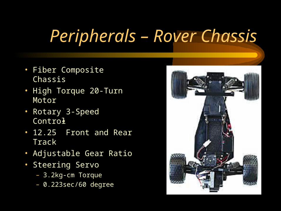
Peripherals – Rover Chassis
• Fiber Composite Chassis
• High Torque 20-Turn Motor
• Rotary 3-Speed Control
• 12.25” Front and Rear Track
• Adjustable Gear Ratio
• Steering Servo– 3.2kg-cm Torque
– 0.223sec/60 degree

Peripherals – Servo Interface
Universal
Servo Param’s
Vbat =8.2V
Vpower =6.2V
fservo =52.08Hz
pservo =20ms
Vp-p =5.7V
Steering Servo Duty
CyclesDneutral =8.2%
Dleft-MAX =10.4%
Dright-MAX =5.9%
Drive Servo DutyCycles
Dneutral =7.8%DMAX =10.4%DMIN =5.7%

Peripherals - GPS
• Trimble AgGPS 124/132– Receiver Specs:
• Size: 14.5cm W * 5.1cm H * 19.5cm D
• Weight: 0.76 Kk (1.68lb)
• Power: 7 Watts (max), 10-32V DC
– Antenna Specs• Size: 15.5 cm D * 14cm H
• Weight: 0.55Kg (1.2lb)

Peripherals – GPS Channels
• General– 12-channel, parallel tracking L1 C/A code and carrier phase filtered
measurements and multi-bit digitizer• Update Rate
– 1 Hz standard; 10Hz optional• Differential Speed Accuracy
– 0.1MPH (0.16KPH)• Differential Position Accuracy
– Less than 1 meter horizontal RMS; At least 5 Satellites, PDOP < 4 and RTCM SC-104 standard format broadcast form Trimble 4000RSI or equivalent reference station
• Time to first Fix– < 30sec (typical)
• NMEA Messages– ALM, GGA, GGL, GSA, GSV, MSS, RMC, VTG, ZDA

Peripherals – Limit Switch
• 2XC12 Enclosed Snap Action Limit Switch– Actuator Short Roller
– Size• 0.69in D * 0.95in H * 1.94in L
– Max Pretravel• 0.106in
– Overtravel• 0.064in
– Operating Force• 8.8-12.3oz
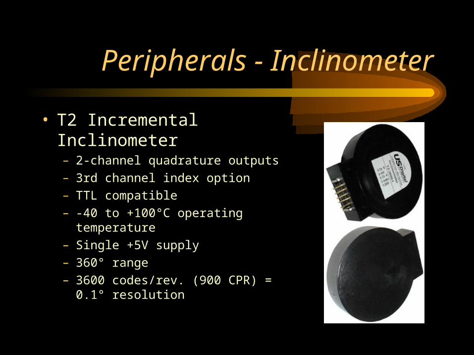
Peripherals - Inclinometer
• T2 Incremental Inclinometer– 2-channel quadrature outputs
– 3rd channel index option
– TTL compatible
– -40 to +100°C operating temperature
– Single +5V supply
– 360° range
– 3600 codes/rev. (900 CPR) = 0.1° resolution

Inclinometer Timing Diagram

Peripherals – Digital Compass
• 1490 Digital Compass– Power
• 5-18 volts DC @ 30 ma – Outputs
• Open collector NPN, sink 25 ma per direction– Weight
• 2.25 grams– Size
• 12.7 mm diameter, 16 mm tall– Pins
• 3 pins on 4 sides on .050 centers– Temp
• -20 to +85 degrees C

Quatech QTM-8524 RF Transceiver
• Power– 10-30 volts DC
• Features– Up to 500 m range with
open line of sight
– Supports baud rates from 600bps-57.6kbps
– Supports RS-232• Has TxD and RxD pins
– Requires external antenna, also provided by Quatech

Digital Camera
• KB Gear Jamcam V 3.0
• System Specs– 640 X 480 Max Resolution
– Serial Output with RS-232 Communications
– Stores up to 8 photos at 640 X 480 and 28 photos at 320 X 240
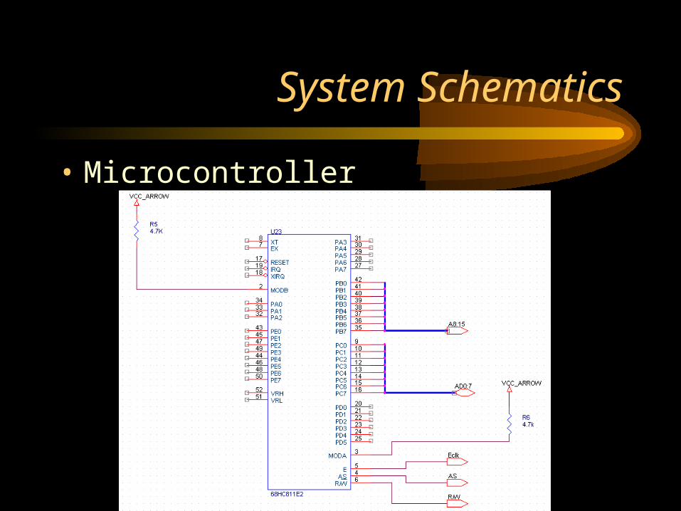
System Schematics
• Microcontroller
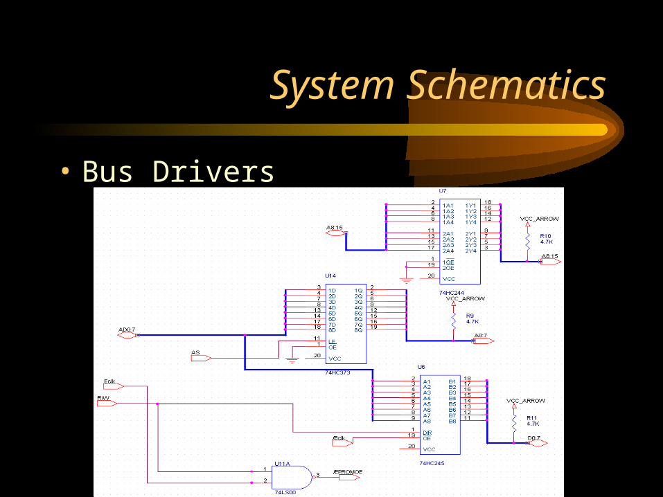
System Schematics
• Bus Drivers

System Schematics
• FPGA and EPROM

Memory Map
• 64 byte Register Block moved to 0000h
• 512 byte Internal RAM moved to 7000h
• External NVRAM mapped to 5000h
• EEPROM removed from B600h
• Memory Mapped IO at 1000h to 4FFFh

Current Status
• Successful Program Fetch and Execution– NOP NOP NOP JMP
• Integrated Xilinx FPGA– Debugging various chip selects
• Boot Monitor

Software Diagram
text
GPS
DigitalCom pass
Inclinom eter
Servos
SerialHandler
HeadingDeterm ination
S lope AngleDeterm ination
ServoControl
Inform ationDecode
SerialHandler
Com m andDecode
RFReceiver
RFTransm itter
Com m and GUIon W orkstation
MAINCONTROL
S oftware R unn ingon 68H C 11
Cam eraCam era
Com m unication

Workstation Software
RFTransm itter
Serial Connectoron W orkstation
File System onW orkstation
Serial Com m andEncoder and Handler
Location DataStorage
GUI
S oftware R unn ingon W orksta tion

Workstation GUI
• Send kill command• View current
waypoints• Set new waypoints• Store waypoint history• View waypoint history

Schedule Update

Division of Labor
• Matt– Finishing Board
– GPS Communications
• Marcin– Finishing Board
– Inclinometer
– Digital Compass
– Camera
• Travis– RF Communications
– Limit Switch
• Phil– Servo control
implementation
– GUI Interface

Conclusions
• Choices about Peripherals
• Progress so far
• Places where we anticipate the most difficulty
• Any Questions?


