Specifications are subject to change without notice.
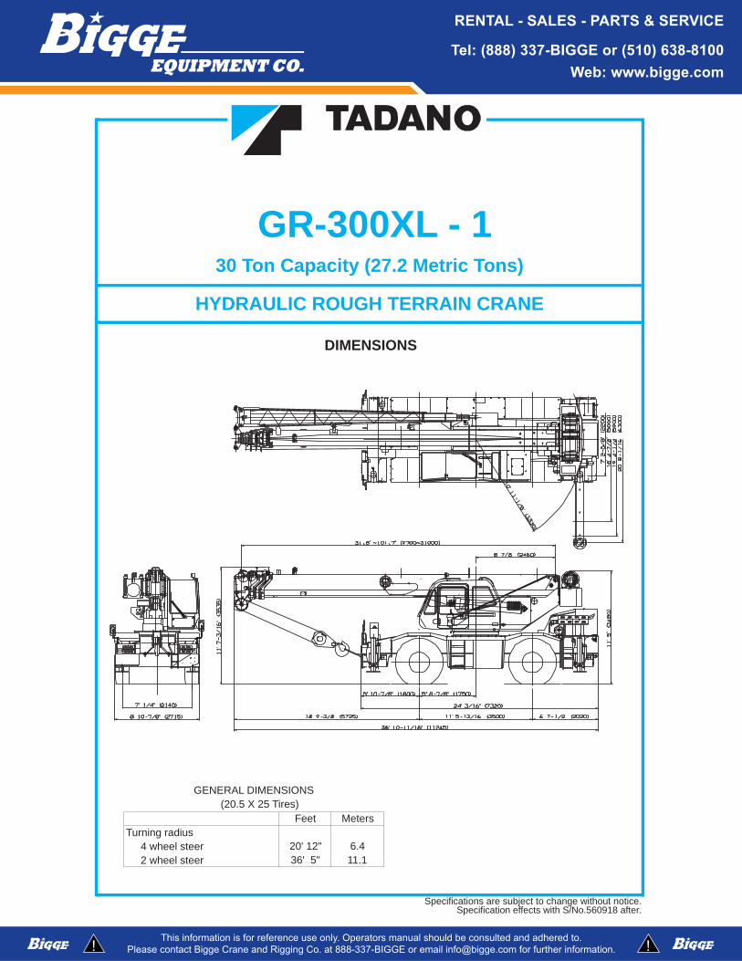
GENERAL DIMENSIONS (20.5 X 25 Tires)
30 Ton Capacity (27.2 Metric Tons)
HYDRAULIC ROUGH TERRAIN CRANE
DIMENSIONS
1Specification effects with S/No.560918 after.
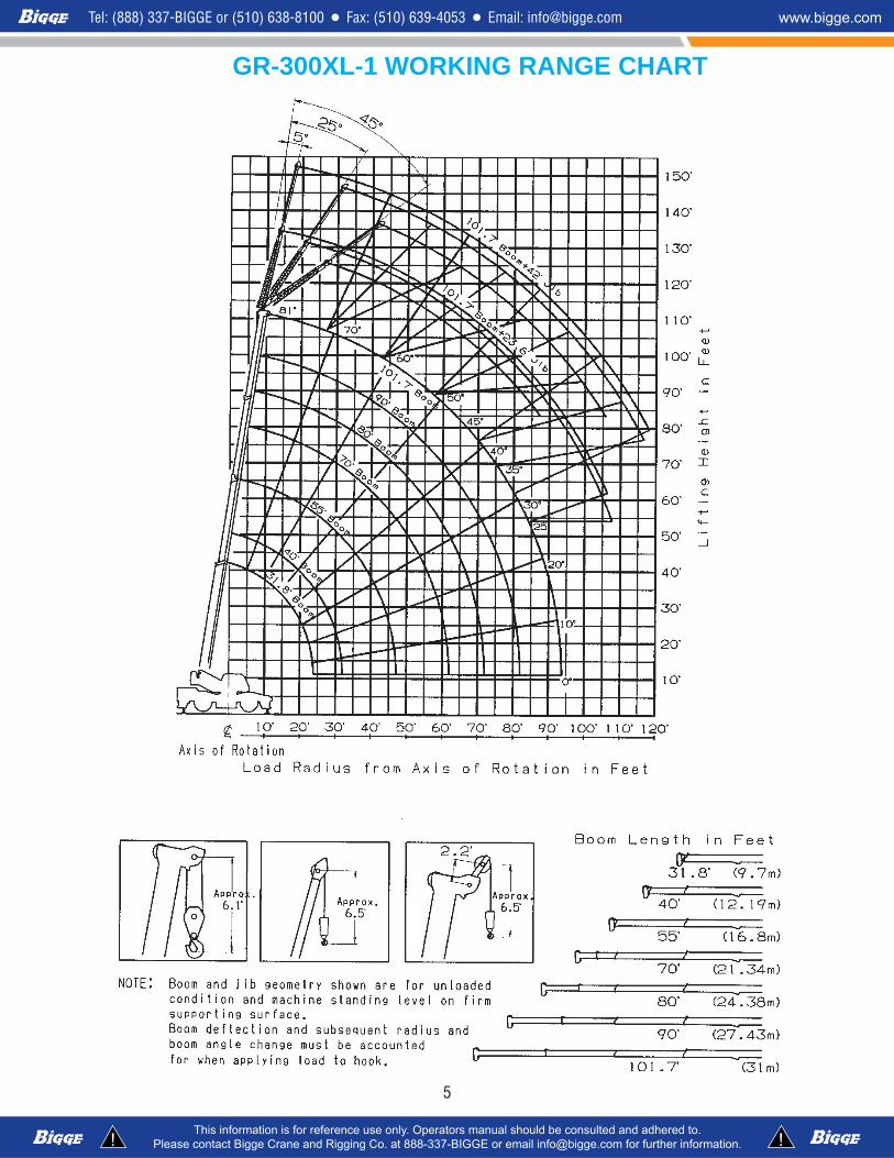
CRANE SPECIFICATIONSBOOM * Maximum permissible line pull may be affected by wire ropeFour section full power synchronized telescoping boom, strength.31.8'~101.7' (9.7m~31.0m), of round hexagonal box construction with three sheaves, 13-1/4" (0.336m) root diameter, at boom head. WIRE ROPE - Warrington seal wire, extra improved plow steel,The synchronization system consists of two double acting telescope preformed, independent wire rope core, right regular lay.cylinders, an extension cable and retraction cable. Hydraulic 5/8"(16 mm) 6X37 classcylinder fitted with holding valve. Two easily removable wire rope guards, rope dead end provided on both sides of boom head. HOOK BLOCKSBoom telescope sections are supported by wear pads both
4.4 ton (4.0 metric ton) - Weighted hook with swivel andBOOM ELEVATION - By a double acting hydraulic cylinder safety latch, for 5/8"(16mm) wire rope.with holding valve. Elevation 0o~81o, combination controls forhand or foot operation. Boom angle indicator.Automatic speed reduction and soft stop function. HYDRAULIC SYSTEMElevating speed 0° to 81° in 44 seconds.
PUMPS - Two variable piston pumps for crane functions.JIB - Two stage lattice type, 5o, 25o or 45o offset (tilt type). Tandem gear pump for steering, swing and optional equipment.Single sheave, 13-7/8"(0.352m) root diameter, at jib head. Powered by carrier engine. Pump disconnect for crane isBox type top section telescopes from lattice type base section engaged/ disengaged by rotary switch from operator's cab.which stores alongside base boom section. Jib length is 23.6' (7.2m) or 42' (12.8m). CONTROL VALVES - Multiple valves actuated by pilot
pressure with integral pressure relief valves.AUXILIARY LIFTING SHEAVE (SINGLE TOP) -Single sheave, 13-1/4"(0.336m) root diameter. Mounted to main RESERVOIR - 100 gallon (380 lit.) capacity. External sight
.eguaglevel.)elbawots(krowenilelgnisrofdaehmoob
ANTI-TWO BLOCK - Pendant type over-winding cut out FILTRATION - 26 micron return filter, full flow with bypassdevice with audio-visual (FAILURE lamp/BUZZER) warning protection, located inside of hydraulic reservoir. Accessible for
.tnemecalperysae.metsys
RELOOCLIOGNIWS - Air cooled fan type.Hydraulic axial piston motor driven through planetary swingspeed reducer. Continuous 360o full circle swing on ball bearingturntable at 2.7rpm. Equipped with manually locked/released CAB AND CONTROLSswing brake. A 360o positive swing lock for pick and carryand travel modes, manually engaged in cab. Twin swing system: Both crane and drive operations can be performed from oneFree swing or lock swing controlled by selector switch on front console. cab mounted on rotating superstructure.Automatic speed reduction and soft stop function.
Left side, 1 man type, steel construction with sliding doorHOIST access and tinted safety glass windows opening at side. Door
window is powered control. Windshield glass window and roofMAIN HOIST - Variable speed type with grooved drum driven glass window are shatter-resistant. Tilt-telescoping steeringby hydraulic axial piston motor through winch speed reducer. wheel. Adjustable control lever stands for swing, boom hoist,Power load lowering and raising. Equipped with automatic boom telescoping, auxiliary hoist and main hoist. Control leverbrake (neutral brake) and counterbalance valve. Controlled stands can change neutral positions and tilt for easy access to independently of auxiliary hoist. Equipped with cable follower cab. Engine throttle knob. Foot operated controls: boom hoist,
retawtoH.elttorhtenignednaekarbecivres,gnipocseletmoob.rotacidninoitatormurddnacab heater and air conditioning (OPTIONAL).
DRUM - Grooved 12-5/8"(0.32m) root diameter x 19-1/16"(0.485m) wide. Wire rope: 558' of 5/8"diameter rope (170m of Dash-mounted engine start/stop, monitor lamps, cigarette16mm). Drum capacity: 720' (219.5m) 6 layers. Maximum line lighter, drive selector switch, parking brake switch, steeringpull (permissible): 12,600lbs. (5,710kg)*. Maximum line speed: mode select switch, power window switch, pump engaged/
AUXILIARY HOIST (OPTIONAL) - Variable speed type selector switch.with grooved drum driven by hydraulic axial piston motorthrough winch speed reducer. Power load lowering and Instruments - Torque converter oil temperature, engine waterraising. Equipped with automatic brake (neutral brake) and temperature, air pressure, fuel, speedometer, tachometer andcounterbalance valve. Controlled independently of main hoist. hour meter. Hydraulic oil pressure is monitored and displayedEquipped with cable follower and drum rotation indicator. on the AML-L display panel.
DRUM - Grooved 12-5/8"(0.32m) root diameter x 10-3/8"(0.263m) wide. Wire rope: 322' of 5/8"diameter rope (98m of16mm). Drum capacity: 392' (119.4m) 6 layers. Maximum linepull (permissible): 12,600lbs. (5,710kg)*. Maximum line speed:410FPM (125m/min).
2
2
Tadano electronic LOAD MOMENT INDICATOR system TADANO AML-L monitors outrigger extended length andGNITFILDETAR"gnidnopserrocehtsmargorpyllacitamotua:gnidulcni)L-LMA(
• Control lever lockout function with audible and visual CAPACITIES" table.)tnemyolped(noisnetxereggirtuolacirtemys-noNdnalacirtemyshtoBgninraw-erp
• .dettimrepsirotacidnisutatstfiL• Outrigger status indicator• Load radius / boom angle / tip height / swing range
radius / rated lifting capacities / actual loads read out emergency outrigger set up key switch, jib equipped/removed • Ratio of actual load moment to rated load moment select switch, boom emergency telescoping switch (2nd and 3rd-Top)
dnarevelkcolgniwS.hctiwslortnocgninoitidnocriadnanoitacidni• Automatic Speed Reduction and Soft Stop function 3 way adjustable seat with high back and seat belt.
on boom elevation and/or swing• Working condition register switch• ETONpmalgninrawlanretxE :Each crane motion speed is based on unladen
conditions.
CARRIER SPECIFICATIONSSUSPENSION - Front: Semi-elliptic leaf springs with hydraulic
TYPE - Rear engine, left hand steering, 4x2 front drive or lockout device. Rear: Semi-elliptic leaf springs with hydraulic4x4 front and rear drive, selected by 2-way manual switch. lockout device.
FRAME - High tensile steel, all welded mono-box construction. BRAKE SYSTEMS - Service: Air over hydraulic disc brakes onall 4 wheels. Parking/Emergency: Spring applied-air released
TRANSMISSION - Electronically controlled full automatic brake acting on input shaft of front axle. Auxiliary: Electro-transmission. Torque converter driving full powershift with pneumatic operated exhaust brake.driving axle selector. 8 forward and 2 reverse speeds, constantmesh. TIRES - 20.5-25 24PR(OR)
4 speeds - high range - 2 wheel drive; 4 wheel drive4 speeds - low range - 4 wheel drive OUTRIGGERS - Four hydraulic beam and jack outriggers.
Vertical jack cylinders equipped with integral holding valve. EachTRAVEL SPEED - 29 mph (47 km/h) outrigger beam and jack is controlled independently from cab.
Beams extend to 20'8-1/16" (6.3 m) center-line and retract toAXLE - Front: Full floating type, steering and driving axle with within 7'2-5/8" (2.2 m) overall width with floats. Outrigger jackplanetary reduction. Rear: Full floating type, steering and driving floats are attached thus eliminating the need to manually axle with planetary reduction and non-spin rear differential. attach and detach them. Controls and sight bubble located in
superstructure cab. Four outrigger extension lengths areSTEERING- Hydraulic power steering controlled by steering provided with corresponding "RATED LIFTING CAPACITIES" forwheel. Three steering modes available: 2 wheel front, 4 wheel crane duty in confined areas. Both symetrical and Non-symetrical
.dettimrepsi)tnemyolped(noisnetxereggirtuo.barcleehw4dnadetanidroocMin. Extension 7' 2-5/8" center to center Mid. Extension 16' 4-7/8" center to centerMid. Extension 19' 4-1/4" center to centerMax. Extension 20' 8-1/16" center to center
Float size (Diameter) 1'3-3/4"(0.4m)ENGINE
ellortnoctatsomreht,erocebutdnaniFrotaidaR7.6BSQsnimmuCledoM dTyp nitceriDe j .ni,naFleseidnoitce (mm) Suction type, 6-blade, 28 (711) dia.No. of cylinders 6 Starting lov42 tCombustion 4 cycle, turbo charged and after cooled Charging 24 volt system, negative groundBoreXStroke, in.(mm) 4.212 X 4.882 (107X124) Battery ma021-2 p. HourDisplacement, cu. in (liters) 409 (6.700) Compressor, air, CFM(l /min) 15.2 CFM (430) at 2,500rpmAir inlet heater 24 volt preheat Horsepower (kW) Gross 215 (129) at 2,500rpmAir cleaner Dry type, replaceable element Torque, Max. ft-lb (kgm) 620 (86) at 1,600rpmOil filter Full flow with replaceable element Capacity, gal.(liters)Fuel filter Full flow with replaceable element Cooling water 2.7 (10)Fuel tank, gal.(liters) 79.2 (300), right side of carrier Lubrication 4.0 (15)
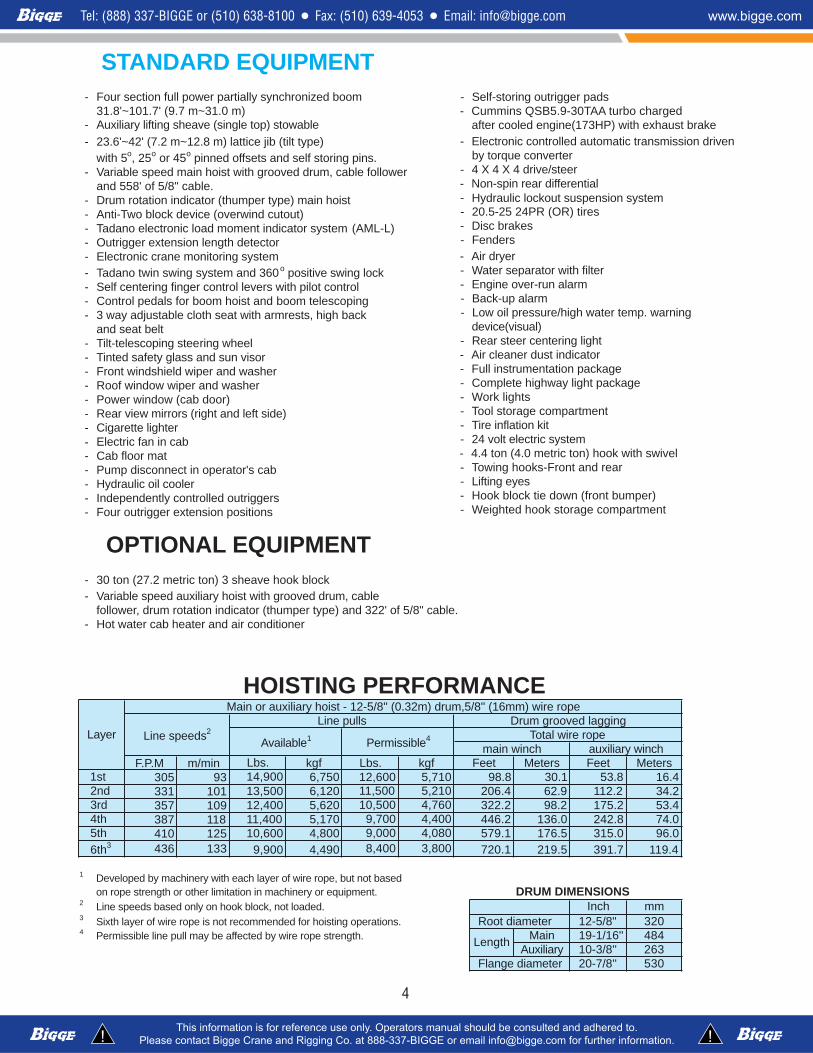
1 Developed by machinery with each layer of wire rope, but not basedon rope strength or other limitation in machinery or equipment. DRUM DIMENSIONS
2 Line speeds based only on hook block, not loaded.3 Sixth layer of wire rope is not recommended for hoisting operations.4 Permissible line pull may be affected by wire rope strength.
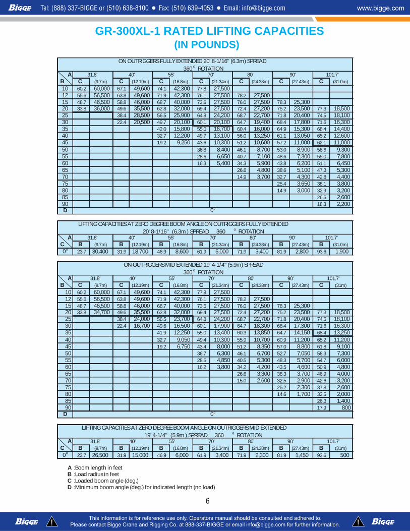
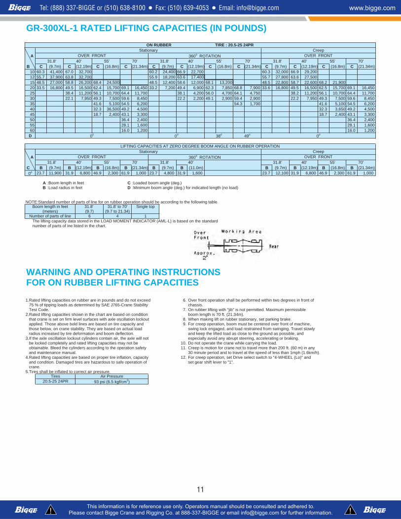
AC B (9.7m) B (12.19m) B (16.8m) B (21.34m) B (24.38m) B (27.43m) B (31.0m)0o 23.7 30,400 31.9 18,700 46.9 8,600 61.9 5,000 71.9 3,400 81.9 2,800 93.6 1,900
A 31.8' 40' 55' 70' 80' 90' 101.7'B C (9.7m) C (12.19m) C (16.8m) C (21.34m) C (24.38m) C (27.43m) C (31m)
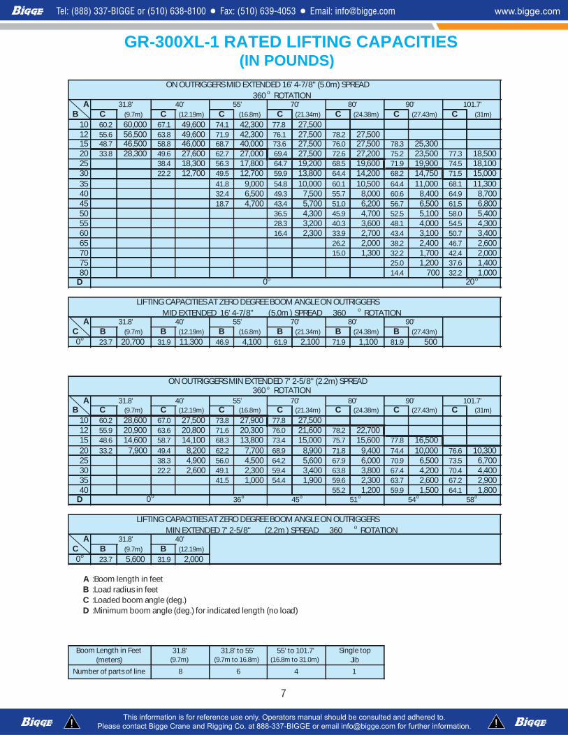
A 31.8' 40' 55' 70' 80' 90' 101.7'C B (9.7m) B (12.19m) B (16.8m) B (21.34m) B (24.38m) B (27.43m) B (31m)0o 23.7 26,500 31.9 15,000 46.9 6,000 61.9 3,400 71.9 2,300 81.9 1,450 93.6 500
A :Boom length in feetB :Load radius in feetC :Loaded boom angle (deg.)D :Minimum boom angle (deg.) for indicated length (no load)
70'
19' 4-1/4'' (5.9m ) SPREAD 360 o ROTATION
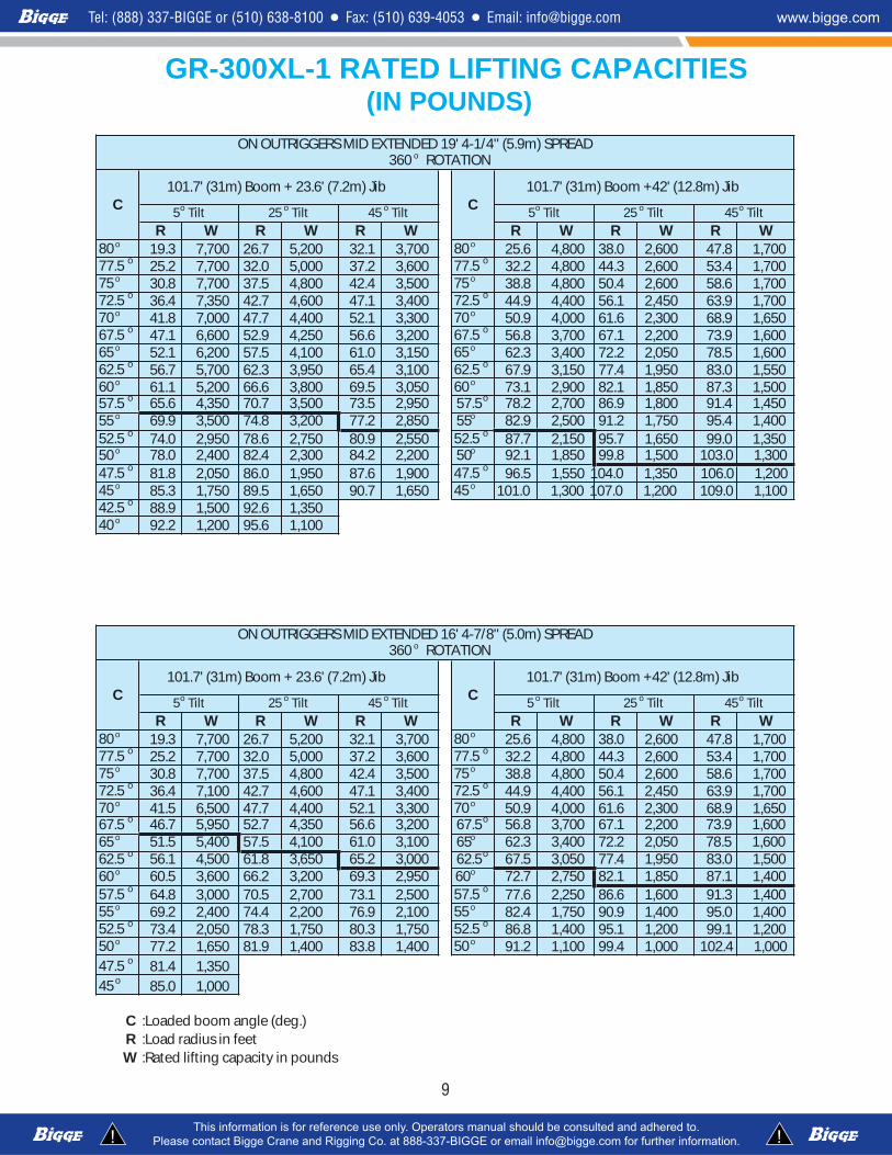
ON OUTRIGGERS MID EXTENDED 19' 4-1/4'' (5.9m) SPREAD360 o ROTATION
0o
LIFTING CAPACITIES AT ZERO DEGREE BOOM ANGLE ON OUTRIGGERS MID EXTENDED
GR-300XL-1 RATED LIFTING CAPACITIES
31.8' 40' 55' 70' 80'
ON OUTRIGGERS FULLY EXTENDED 20' 8-1/16'' (6.3m) SPREAD
101.7'90'360 o ROTATION
(IN POUNDS)
80' 90' 101.7'20' 8-1/16'' (6.3m ) SPREAD 360 o ROTATION
0o
LIFTING CAPACITIES AT ZERO DEGREE BOOM ANGLE ON OUTRIGGERS FULLY EXTENDED
31.8' 40' 55'
6 6
A 31.8' 40' 55' 70' 80' 90' 101.7'B C (9.7m) C (12.19m) C (16.8m) C (21.34m) C (24.38m) C (27.43m) C (31m)
A 31.8' 40' 55' 70' 80' 90'C B (9.7m) B (12.19m) B (16.8m) B (21.34m) B (24.38m) B (27.43m)0o 23.7 20,700 31.9 11,300 46.9 4,100 61.9 2,100 71.9 1,100 81.9 500
A 31.8' 40' 55' 70' 80' 90' 101.7'B C (9.7m) C (12.19m) C (16.8m) C (21.34m) C (24.38m) C (27.43m) C (31m)
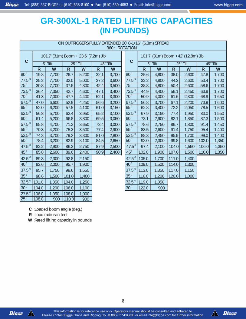
R W R W R W R W R W R W80 o 19.3 7,700 26.7 5,200 32.1 3,700 80 o 25.6 4,800 38.0 2,600 47.8 1,70077.5 o 25.2 7,700 32.0 5,000 37.2 3,600 77.5 o 32.2 4,800 44.3 2,600 53.4 1,70075 o 30.8 7,700 37.5 4,800 42.4 3,500 75 o 38.8 4,800 50.4 2,600 58.6 1,70072.5 o 36.4 7,350 42.7 4,600 47.1 3,400 72.5 o 44.9 4,400 56.1 2,450 63.9 1,70070 o 41.8 7,000 47.7 4,400 52.1 3,300 70 o 50.9 4,000 61.6 2,300 68.9 1,65067.5 o 47.1 6,600 52.9 4,250 56.6 3,200 67.5 o 56.8 3,700 67.1 2,200 73.9 1,60065 o 52.1 6,200 57.5 4,100 61.0 3,150 65 o 62.3 3,400 72.2 2,050 78.5 1,60062.5 o 56.7 5,700 62.3 3,950 65.4 3,100 62.5 o 67.9 3,150 77.4 1,950 83.0 1,55060 o 61.1 5,200 66.6 3,800 69.5 3,050 60 o 73.1 2,900 82.1 1,850 87.3 1,50057.5 o 65.6 4,350 70.7 3,500 73.5 2,950 57.5o 78.2 2,700 86.9 1,800 91.4 1,45055 o 69.9 3,500 74.8 3,200 77.2 2,850 55o 82.9 2,500 91.2 1,750 95.4 1,40052.5 o 74.0 2,950 78.6 2,750 80.9 2,550 52.5 o 87.7 2,150 95.7 1,650 99.0 1,35050 o 78.0 2,400 82.4 2,300 84.2 2,200 50o 92.1 1,850 99.8 1,500 103.0 1,30047.5 o 81.8 2,050 86.0 1,950 87.6 1,900 47.5 o 96.5 1,550 104.0 1,350 106.0 1,20045 o 85.3 1,750 89.5 1,650 90.7 1,650 45 o 101.0 1,300 107.0 1,200 109.0 1,10042.5 o 88.9 1,500 92.6 1,35040 o 92.2 1,200 95.6 1,100
R W R W R W R W R W R W80 o 19.3 7,700 26.7 5,200 32.1 3,700 80 o 25.6 4,800 38.0 2,600 47.8 1,70077.5 o 25.2 7,700 32.0 5,000 37.2 3,600 77.5 o 32.2 4,800 44.3 2,600 53.4 1,70075 o 30.8 7,700 37.5 4,800 42.4 3,500 75 o 38.8 4,800 50.4 2,600 58.6 1,70072.5 o 36.4 7,100 42.7 4,600 47.1 3,400 72.5 o 44.9 4,400 56.1 2,450 63.9 1,70070 o 41.5 6,500 47.7 4,400 52.1 3,300 70 o 50.9 4,000 61.6 2,300 68.9 1,65067.5 o 46.7 5,950 52.7 4,350 56.6 3,200 67.5o 56.8 3,700 67.1 2,200 73.9 1,60065 o 51.5 5,400 57.5 4,100 61.0 3,100 65o 62.3 3,400 72.2 2,050 78.5 1,60062.5 o 56.1 4,500 61.8 3,650 65.2 3,000 62.5o 67.5 3,050 77.4 1,950 83.0 1,50060 o 60.5 3,600 66.2 3,200 69.3 2,950 60o 72.7 2,750 82.1 1,850 87.1 1,40057.5 o 64.8 3,000 70.5 2,700 73.1 2,500 57.5 o 77.6 2,250 86.6 1,600 91.3 1,40055 o 69.2 2,400 74.4 2,200 76.9 2,100 55 o 82.4 1,750 90.9 1,400 95.0 1,40052.5 o 73.4 2,050 78.3 1,750 80.3 1,750 52.5 o 86.8 1,400 95.1 1,200 99.1 1,20050 o 77.2 1,650 81.9 1,400 83.8 1,400 50 o 91.2 1,100 99.4 1,000 102.4 1,00047.5 o 81.4 1,35045 o 85.0 1,000
C :Loaded boom angle (deg.)R :Load radius in feetW :Rated lifting capacity in pounds
GR-300XL-1 RATED LIFTING CAPACITIES(IN POUNDS)
ON OUTRIGGERS MID EXTENDED 19' 4-1/4'' (5.9m) SPREAD360 o ROTATION
C101.7' (31m) Boom +42' (12.8m) Jib
45o Tilt5o Tilt 25 o Tilt
ON OUTRIGGERS MID EXTENDED 16' 4-7/8'' (5.0m) SPREAD
45o Tilt
C101.7' (31m) Boom + 23.6' (7.2m) Jib
5o Tilt 25 o Tilt 45 o Tilt
360 o ROTATION
C101.7' (31m) Boom + 23.6' (7.2m) Jib
C101.7' (31m) Boom +42' (12.8m) Jib
5o Tilt 25 o Tilt 45 o Tilt 5 o Tilt 25 o Tilt
9
9
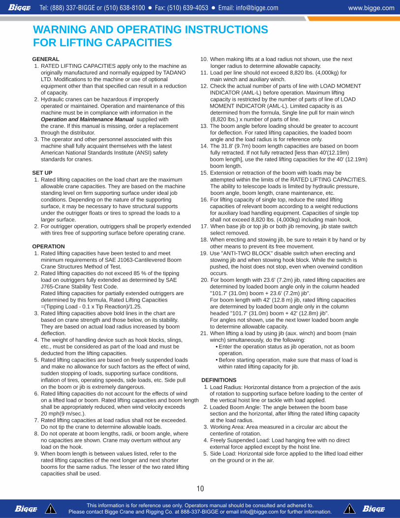
WARNING AND OPERATING INSTRUCTIONSFOR LIFTING CAPACITIESGENERAL 10. When making lifts at a load radius not shown, use the next1. RATED LIFTING CAPACITIES apply only to the machine as longer radius to determine allowable capacity.
originally manufactured and normally equipped by TADANO 11. Load per line should not exceed 8,820 lbs. (4,000kg) forLTD. Modifications to the machine or use of optional main winch and auxiliary winch.equipment other than that specified can result in a reduction 12. Check the actual number of parts of line with LOAD MOMENTof capacity. INDICATOR (AML-L) before operation. Maximum lifting
2. Hydraulic cranes can be hazardous if improperly capacity is restricted by the number of parts of line of LOADoperated or maintained. Operation and maintenance of this MOMENT INDICATOR (AML-L). Limited capacity is asmachine must be in compliance with information in the determined from the formula, Single line pull for main winchOperation and Maintenance Manual supplied with (8,820 lbs.) x number of parts of line.the crane. If this manual is missing, order a replacement 13. The boom angle before loading should be greater to accountthrough the distributor. for deflection. For rated lifting capacities, the loaded boom
3. The operator and other personnel associated with this angle and the load radius is for reference only.machine shall fully acquaint themselves with the latest 14. The 31.8' (9.7m) boom length capacities are based on boomAmerican National Standards Institute (ANSI) safety fully retracted. If not fully retracted [less than 40'(12.19m)standards for cranes. boom length], use the rated lifting capacities for the 40' (12.19m)
boom length.SET UP 15. Extension or retraction of the boom with loads may be1. Rated lifting capacities on the load chart are the maximum attempted within the limits of the RATED LIFTING CAPACITIES.
allowable crane capacities. They are based on the machine The ability to telescope loads is limited by hydraulic pressure,standing level on firm supporting surface under ideal job boom angle, boom length, crane maintenance, etc.conditions. Depending on the nature of the supporting 16. For lifting capacity of single top, reduce the rated liftingsurface, it may be necessary to have structural supports capacities of relevant boom according to a weight reductionsunder the outrigger floats or tires to spread the loads to a for auxiliary load handling equipment. Capacities of single top larger surface. shall not exceed 8,820 lbs. (4,000kg) including main hook.
2. For outrigger operation, outriggers shall be properly extended 17. When base jib or top jib or both jib removing, jib state switchwith tires free of supporting surface before operating crane. select removed.
18. When erecting and stowing jib, be sure to retain it by hand or byOPERATION other means to prevent its free movement.1. Rated lifting capacities have been tested to and meet 19. Use "ANTI-TWO BLOCK" disable switch when erecting and
minimum requirements of SAE J1063-Cantilevered Boom stowing jib and when stowing hook block. While the switch isCrane Structures Method of Test. pushed, the hoist does not stop, even when overwind condition
2. Rated lifting capacities do not exceed 85 % of the tipping occurs.load on outriggers fully extended as determined by SAE 20. For boom length with 23.6' (7.2m) jib, rated lifting capacities areJ765-Crane Stability Test Code. determined by loaded boom angle only in the column headedRated lifting capacities for partially extended outriggers are "101.7' (31.0m) boom + 23.6' (7.2m) jib". determined by this formula, Rated Lifting Capacities For boom length with 42' (12.8 m) jib, rated lifting capacities=(Tipping Load - 0.1 x Tip Reaction)/1.25. are determined by loaded boom angle only in the column
3. Rated lifting capacities above bold lines in the chart are headed "101.7' (31.0m) boom + 42' (12.8m) jib". based on crane strength and those below, on its stability. For angles not shown, use the next lower loaded boom angleThey are based on actual load radius increased by boom to determine allowable capacity. deflection. 21. When lifting a load by using jib (aux. winch) and boom (main
4. The weight of handling device such as hook blocks, slings, winch) simultaneously, do the following:etc., must be considered as part of the load and must be Enter the operation status as jib operation, not as boomdeducted from the lifting capacities. operation.
5. Rated lifting capacities are based on freely suspended loads Before starting operation, make sure that mass of load isand make no allowance for such factors as the effect of wind, within rated lifting capacity for jib.sudden stopping of loads, supporting surface conditions,inflation of tires, operating speeds, side loads, etc. Side pull DEFINITIONSon the boom or jib is extremely dangerous. 1. Load Radius: Horizontal distance from a projection of the axis
6. Rated lifting capacities do not account for the effects of wind of rotation to supporting surface before loading to the center ofon a lifted load or boom. Rated lifting capacities and boom length the vertical hoist line or tackle with load applied.shall be appropriately reduced, when wind velocity exceeds 2. Loaded Boom Angle: The angle between the boom base20 mph(9 m/sec.). section and the horizontal, after lifting the rated lifting capacity
7. Rated lifting capacities at load radius shall not be exceeded. at the load radius.Do not tip the crane to determine allowable loads. 3. Working Area: Area measured in a circular arc about the
8. Do not operate at boom lengths, radii, or boom angle, where centerline of rotation.no capacities are shown. Crane may overturn without any 4. Freely Suspended Load: Load hanging free with no directload on the hook. external force applied except by the hoist line.
9. When boom length is between values listed, refer to the 5. Side Load: Horizontal side force applied to the lifted load eitherrated lifting capacities of the next longer and next shorter on the ground or in the air.booms for the same radius. The lesser of the two rated liftingcapacities shall be used.
B C (9.7m) C (12.19m) C (16.8m) C (21.34m) C (9.7m) C (12.19m) C (16.8m) C (21.34m) C (9.7m) C (12.19m) C (16.8m) C (21.34m)002,929.66000,233.06007,229.66004,422.06007,230.76004,143.0601005,726.36008,727.55004,716.36002,819.55007,238.36009,737.5521
C B (9.7m) B (12.19m) B (16.8m) B (21.34m) B (9.7m) B (11.0m) B (9.7m) B (12.19m) B (16.8m) B (21.34m)0o 000,19.16003,29.64008,69.13001,217.32006,19.13008,47.32000,19.16003,29.64008,69.13009,117.32
A :Boom length in feet C :Loaded boom angle (deg.)B :Load radius in feet D :Minimum boom angle (deg.) for indicated length (no load)
NOTE:Standard number of parts of line for on rubber operation should be according to the following table.
The lifting capacity data stored in the LOAD MOMENT INDICATOR (AML-L) is based on the standard number of parts of ine listed in the chart.
WARNING AND OPERATING INSTRUCTIONSFOR ON RUBBER LIFTING CAPACITIES
1.Rated lifting capacities on rubber are in pounds and do not exceed 6. Over front operation shall be performed within two degrees in front of 75 % of tipping loads as determined by SAE J765-Crane Stability chassis. Test Code. 7. On rubber lifting with "jib" is not permitted. Maximum permissible2.Rated lifting capacities shown in the chart are based on condition boom length is 70 ft. (21.34m). that crane is set on firm level surfaces with axle oscillation lockout 8. When making lift on rubber stationary, set parking brake. applied. Those above bold lines are based on tire capacity and 9. For creep operation, boom must be centered over front of machine,
3.If the axle oscillation lockout cylinders contain air, the axle will not especially avoid any abrupt steering, accelerating or braking..daolehtgniyrracelihwenarcehtetarepotonoD.01ebtonyamseiticapacgnitfildetardnayletelpmocdekcoleb
obtainable. Bleed the cylinders according to the operation safety 11. Creep is motion for crane not to travel more than 200 ft. (60 m) in any.)h/mk6.1(hpm1nahtsselfodeepsehttalevartotdnadoirepetunim03.launamecnanetniamdna
4.Rated lifting capacities are based on proper tire inflation, capacity 12. For creep operation, set Drive select switch to "4-WHEEL (Lo)" and and condition. Damaged tires are hazardous to safe operation of set gear shift lever to "1". crane.5.Tires shall be inflated to correct air pressure.
CreepOVER FRONT
49o
LIFTING CAPACITIES AT ZERO DEGREE BOOM ANGLE ON RUBBER OPERATION
38o0o 0o 0o
20.5-25 24PR 93 psi (6.5 kgf/cm2)
1enilfostrapforebmuN 6 4
Tires Air Pressure
(meters) (9.7) (9.7 to 21.34)potelgniSteefnihtgnelmooB
StationaryOVER FRONT 360o ROTATION
31.8' 31.8' to 70'
ON RUBBER TIRE : 20.5-25 24PRStationary Creep
OVER FRONT 360o ROTATION OVER FRONT
11
11
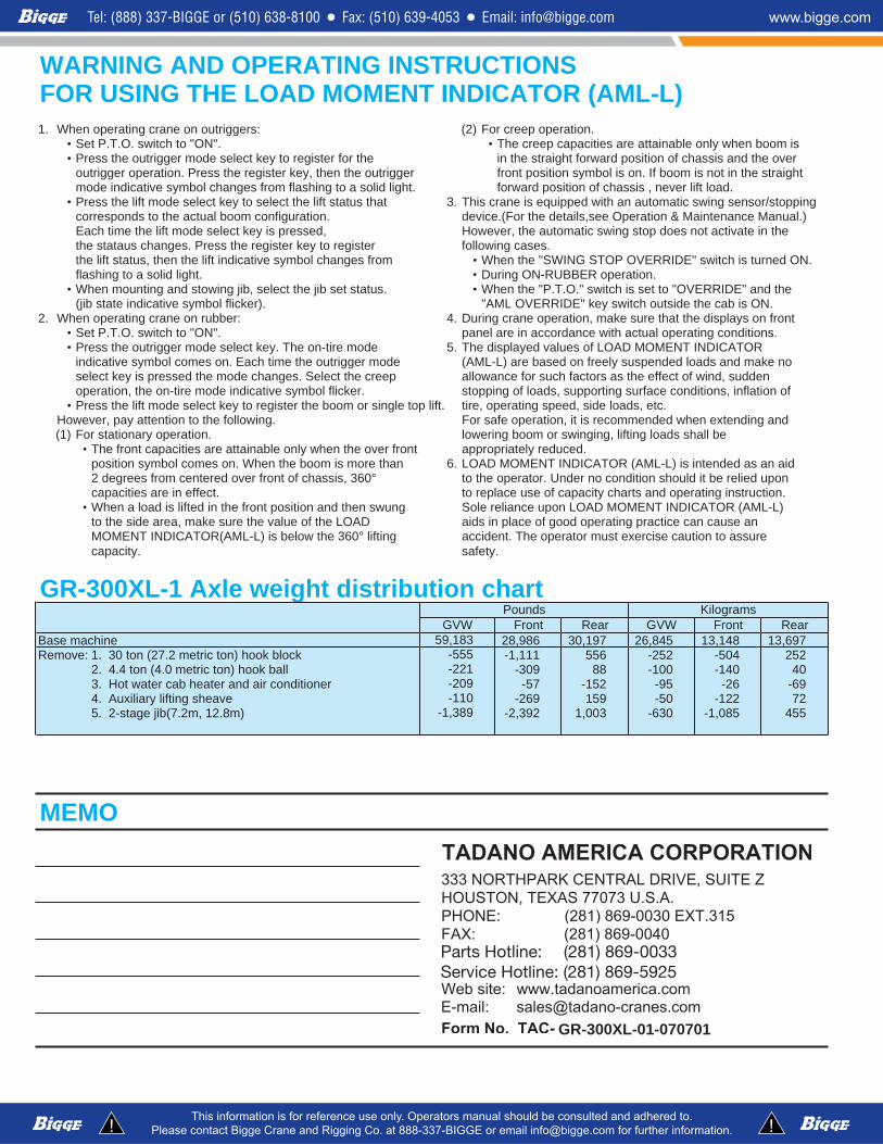
WARNING AND OPERATING INSTRUCTIONSFOR USING THE LOAD MOMENT INDICATOR (AML-L)
.noitarepopeercroF)2(:sreggirtuonoenarcgnitareponehW.1• Set P.T.O. switch to "ON". • The creep capacities are attainable only when boom is• Press the outrigger mode select key to register for the in the straight forward position of chassis and the over
outrigger operation. Press the register key, then the outrigger front position symbol is on. If boom is not in the straight mode indicative symbol changes from flashing to a solid light. forward position of chassis , never lift load.
• Press the lift mode select key to select the lift status that 3. This crane is equipped with an automatic swing sensor/stopping ).launaMecnanetniaM&noitarepOees,sliatedehtroF(.ecived.noitarugifnocmooblautcaehtotsdnopserroc
ehtnietavitcatonseodpotsgniwscitamotuaeht,revewoH,desserpsiyektcelesedomtfilehtemithcaEthe stataus changes. Press the register key to register following cases.the lift status, then the lift indicative symbol changes from • When the "SWING STOP OVERRIDE" switch is turned ON.flashing to a solid light. • During ON-RUBBER operation.
• When mounting and stowing jib, select the jib set status. • When the "P.T.O." switch is set to "OVERRIDE" and the.NOsibacehtedistuohctiwsyek"EDIRREVOLMA".)rekcilflobmysevitacidnietatsbij(
tnorfnosyalpsidehttahterusekam,noitarepoenarcgniruD.4:rebburnoenarcgnitareponehW.2• .snoitidnocgnitarepolautcahtiwecnadroccanieralenap."NO"othctiws.O.T.PteS• Press the outrigger mode select key. The on-tire mode 5. The displayed values of LOAD MOMENT INDICATOR
indicative symbol comes on. Each time the outrigger mode (AML-L) are based on freely suspended loads and make noselect key is pressed the mode changes. Select the creep allowance for such factors as the effect of wind, suddenoperation, the on-tire mode indicative symbol flicker. stopping of loads, supporting surface conditions, inflation of
• Press the lift mode select key to register the boom or single top lift. tire, operating speed, side loads, etc. dnagnidnetxenehwdednemmocersiti,noitarepoefasroF.gniwollofehtotnoitnettayap,revewoH
ebllahssdaolgnitfil,gnigniwsromoobgnirewol.noitarepoyranoitatsroF)1(• The front capacities are attainable only when the over front appropriately reduced.
position symbol comes on. When the boom is more than 6. LOAD MOMENT INDICATOR (AML-L) is intended as an aid2 degrees from centered over front of chassis, 360° to the operator. Under no condition should it be relied upon
.noitcurtsnignitarepodnastrahcyticapacfoesuecalperot.tceffenieraseiticapac• When a load is lifted in the front position and then swung Sole reliance upon LOAD MOMENT INDICATOR (AML-L)
to the side area, make sure the value of the LOAD aids in place of good operating practice can cause anMOMENT INDICATOR(AML-L) is below the 360° lifting accident. The operator must exercise caution to assure