GRACE: Generative Robust Analog Circuit Exploration Michael A. Terry, Jonathan Marcus, Matthew Farrell, Varun Aggarwal, Una-May O’Reilly Computer Science and Artificial Intelligence Lab (CSAIL) Massachusetts Institute of Technology Cambridge, MA, USA m [email protected], [email protected]Abstract. We motivate and describe an analog evolvable hardware de- sign platform named GRACE (i.e. Generative Robust Analog Circuit Ex- ploration). GRACE combines coarse-grained, topological circuit search with intrinsic testing on a Commercial Off-The-Shelf (COTS) field pro- grammable device, the Anadigm AN221E04. It is suited for adaptive, fault tolerant system design as well as CAD flow applications. 1 Introduction With our Generative Robust Analog Ciruit Exploration (GRACE) tool we are investigating whether it is possible to evolve circuits that can be realized effi- ciently and in a routine manner. We are focusing upon the domain of analog circuit design. Our decision is motivated by the lack of automation in analog de- sign as compared to digital design. We intend to investigate whether evolvable hardware (EHW) approaches can contribute to the complex, human-intensive activity domain of analog design. The goal of this paper is to describe how we arrived at GRACE. By com- bining the exploitation of coarse grained elements with intrinsic testing, we think GRACE sits in an interesting and novel space. It allows a distinctive foray into on-line adaptive and fault tolerant evolvable hardware circuits since it uses a COTS (Commercial-Off-The-Shelf) device and standard components. This should make its results more acceptable to industry. It also allows an eco- nomical and time efficient foray into the broad domain of VLSI and CAD with its use of elements that are conversant with human design. We proceed thus: In Sec- tion 2 we describe how we reached a decision to select the Anadigm AN221E04 as GRACE’s reconfigurable device. In Section 3 we give an overview of GRACE. In Section 4 we describe GRACE’s genetic representation of a circuit and its search algorithms. In Section 5 we design a controller for a plant using GRACE to demonstrate its ability to evolve circuits. We conclude with a summary.
Transcript
GRACE: Generative Robust Analog CircuitExploration
Michael A. Terry, Jonathan Marcus, Matthew Farrell, Varun Aggarwal,Una-May O’Reilly
Computer Science and Artificial Intelligence Lab (CSAIL)Massachusetts Institute of Technology
Abstract. We motivate and describe an analog evolvable hardware de-sign platform named GRACE (i.e. Generative Robust Analog Circuit Ex-ploration). GRACE combines coarse-grained, topological circuit searchwith intrinsic testing on a Commercial Off-The-Shelf (COTS) field pro-grammable device, the Anadigm AN221E04. It is suited for adaptive,fault tolerant system design as well as CAD flow applications.
1 Introduction
With our Generative Robust Analog Ciruit Exploration (GRACE) tool we areinvestigating whether it is possible to evolve circuits that can be realized effi-ciently and in a routine manner. We are focusing upon the domain of analogcircuit design. Our decision is motivated by the lack of automation in analog de-sign as compared to digital design. We intend to investigate whether evolvablehardware (EHW) approaches can contribute to the complex, human-intensiveactivity domain of analog design.
The goal of this paper is to describe how we arrived at GRACE. By com-bining the exploitation of coarse grained elements with intrinsic testing, wethink GRACE sits in an interesting and novel space. It allows a distinctiveforay into on-line adaptive and fault tolerant evolvable hardware circuits sinceit uses a COTS (Commercial-Off-The-Shelf) device and standard components.This should make its results more acceptable to industry. It also allows an eco-nomical and time efficient foray into the broad domain of VLSI and CAD with itsuse of elements that are conversant with human design. We proceed thus: In Sec-tion 2 we describe how we reached a decision to select the Anadigm AN221E04as GRACE’s reconfigurable device. In Section 3 we give an overview of GRACE.In Section 4 we describe GRACE’s genetic representation of a circuit and itssearch algorithms. In Section 5 we design a controller for a plant using GRACEto demonstrate its ability to evolve circuits. We conclude with a summary.
2 Choosing GRACE’s Reconfigurable Device
For GRACE, the choice of its reconfigurable device was driven by three criteria(see [1] for a related discussion):
1. A desire to work at an abstraction level where the human design principlesare inherent in the building blocks so that GRACE will derive conventional,human-competent, portable and robust circuits;
2. Availability of a reconfigurable device that matched the project’s budget of$5K;
3. Flexibility that would allow design elements to be chosen depending uponthe design problem, (i.e. level of hierarchy in the analog design flow).
Among the devices we assessed for our purposes were the class of custom designedField Programmable Transistor Arrays (FPTA), the Lattice Semiconductor isp-PAC10 field programmable analog array (FPAA, e.g. [2]), and the AnadigmFPAA family ([3]).
With respect to Criterion 1, there are open questions regarding the suitabilityof an FPTA for evolving conventional, human-competent circuits:
1. Can an FPTA be configured to respect certain design principles so that in-terconnections of the transistor-switched cells and inter-cell topology willconstitute circuits that a human engineer will trust? Some of these designprinciples such as no floating gates could be encoded in the circuit construc-tion and circuit modification functions of an evolutionary algorithm. How-ever, not all expectations/insights (such as parasitic insensitive connections)can be mapped into rules.
2. Can the non-idealities arising from the switching elements in the FPTAs becircumvented to avoid reliability, portability and engineering acceptance is-sues? The FPTAs require electronic switches that are implemented by trans-mission gates. This adds parasitic non-linear resistance and capacitance,which results in delay, de-amplification and alteration in frequency domainproperties. While some of the evolved circuits to date use these non-idealitiesof switches as an integral feature of the design [4], realistically this makesthe evolved design idiosyncratic (i.e. unportable) and unreliable since thebehavior of its switches is neither characterizable or replicable.
3. Is there sufficient flexibility for sizing? Industry practice is to explore sizingoptions as a means of balancing functional goals and specifications. Becauseit only has one size of transistor, the FPTA-2 ([1] )is constrained in thisrespect.
FPTAs are well suited for the exploration of non-conventional realms of cir-cuit design such as polymorphic circuits, extreme temperature electronics andfault tolerant circuits [5–7]. However, they are not well suited to our desire toexplore robust, novel topologies of interpretable and portable circuits.
Circuit synthesis with opamps has straightforward and methodical designrules (which can be easily incorporated in the evolutionary algorithm) to ensure
that the evolved circuit is interpretable and robust. The IsPAC10 and AnadigmFPAA have circuit elements based on opamps. The IsPAC10, see Figure 1 right,consists of 4 programmable analog modules (4 opamps, and 8 input amplifierstotal) interconnected with programmable switching networks. Configuration ofthe IsPAC10 is a proprietary process [2] . The Anadigm AN221E04, see Fig-ure 1 left (and described in more detail in Section 2.1), also provides opampbased circuits as building blocks. It uses switched-capacitor technology which isinherently robust and portable.
With respect to Criterion 2, the cost of an FPTA is beyond $5K. The de-velopment board of an IsPAC10 or Anadigm AN221E04 has a cost in the lowhundreds of dollars. Integrated with a conventional computer and other signalprocessing devices, they facilitate a system with cost below $5K.
Wth respect to Criterion 3, each device we assessed offers a different levelof circuit element granularity. The FPTAs are very flexible, fine-grained devicesThe U. of Heidelberg’s FPTA ([8], henceforth called FPTA-H) is a switchednetwork of 256 (16 X 16) programmable CMOS transistors (half NMOS andhalf PMOS) arranged in a checkerboard pattern.
The FPTA-1 designed at JPL ( [4, 9]) is composed of 12 cells, where each cellcontains 8 CMOS transistors interconnectable via 24 switches. The transistorsare fixed size and the switches are electronically programmable. The FPTA-1appears to have been a prototype device for FPTA-2. The FPTA-2 ([1]) containsan 8X8 matrix of 64 reconfigurable cells, where each cell consists of 14 transistorsinterconnectable via 44 switches. The transistors are fixed size. Each cell alsocontains three capacitors, two reconfigurable resistors and photodetectors. Itfits into the Evolution-Oriented Reconfigurable Architecture (EORA) and isintegrated with a DSP processor running the evolutionary algorithm to form theSABLES (Stand-Alone Board-Level Evolvable System).
FPTA-H is more versatile than FPTA-2 with respect to interconnection andsizing of transistors. In FPTA-H, in general any transistor can connect to anyother transistor, while in FPTA-2, transistors are arranged in a particular topol-ogy with switches to realize different circuits. Even though the FPTA-2 cell has44 switches which creates a large space of possible realizable topologies, thereare human-conceivable designs which cannot be directly synthesized using it. InFPTA-H, 75 different aspect ratios could be chosen for each transistor, while theFPTA-2 uses fixed length transistors. This flexibility of FPTA-H comes at thecost of space (equivalent to the number of transistors that can be fabricated onthe same chip). The FPTA-2 has 3.5 times more transistors on the same chip ascompared to FPTA-H. This difference may also be attributed to the fact thatFPTA-2 uses 0.18µm process, while FPTA-H uses 0.6µm process.
The IsPAC10 and Anadigm AN221E04 exemplify a tradeoff between flexibil-ity and appropriate building block abstraction. The opamp is a building blockthat can be combined with passive components to arrive at variety of human-designed circuits such as amplifiers, integrators, differentiators, sum-differenceamplifiers, or filters. However, it is not as flexible as a switched transistor array.On the IsPAC10, there is very limited interconnect between a small quantity of
resources. The Anadigm AN221E04 provides a fixed abstraction level of opampbased circuits but supports very flexible interconnection.
After our assessment, we chose the Anadigm AN221E04 over the IsPAC10 oran FPTA. In a nutshell, we have forgone a large degree of flexibility by choosinga fixed abstraction level (of opamp based circuits) in order to ensure robustness,portability and reliability. Nonetheless we are content given that there are anumber of analog design problems (such as PID controllers, ADCs and filters)which can be addressed by the given design abstraction. More details of theAnadigm AN221E04 are provided in the next section.
For detailed description of the Anadigm Vortex family of devices, see [3].
Resources: The Anadigm AN221E04 is an array of CABs (configurable analogblocks), each of which contain two opamps, 8 capacitors, a comparator, and aSuccessive Approximation Register (SAR) that performs 8-bit analog-to-digitalconversion of signals. The device also contains one programmable lookup tablethat can be used to store information about the generation of arbitrary wave-forms, and is shared amongst the CABs. The architecture is illustrated in the lefthand block diagram of Figure 1. Any signal can be routed to the I/O pins of thedevice through 4 programmable I/O interface blocks and two dedicated outputs,each of which can also act as a filter or amplifier. The option for expanding thenumber of resources is to daisy chain multiple devices.
Configurable Elements: Despite the existence of opamps and switched ca-pacitors, the Anadigm AN221E04 does not support circuit design at this levelof granularity. Instead, a circuit must be specified at the abstraction of coarser
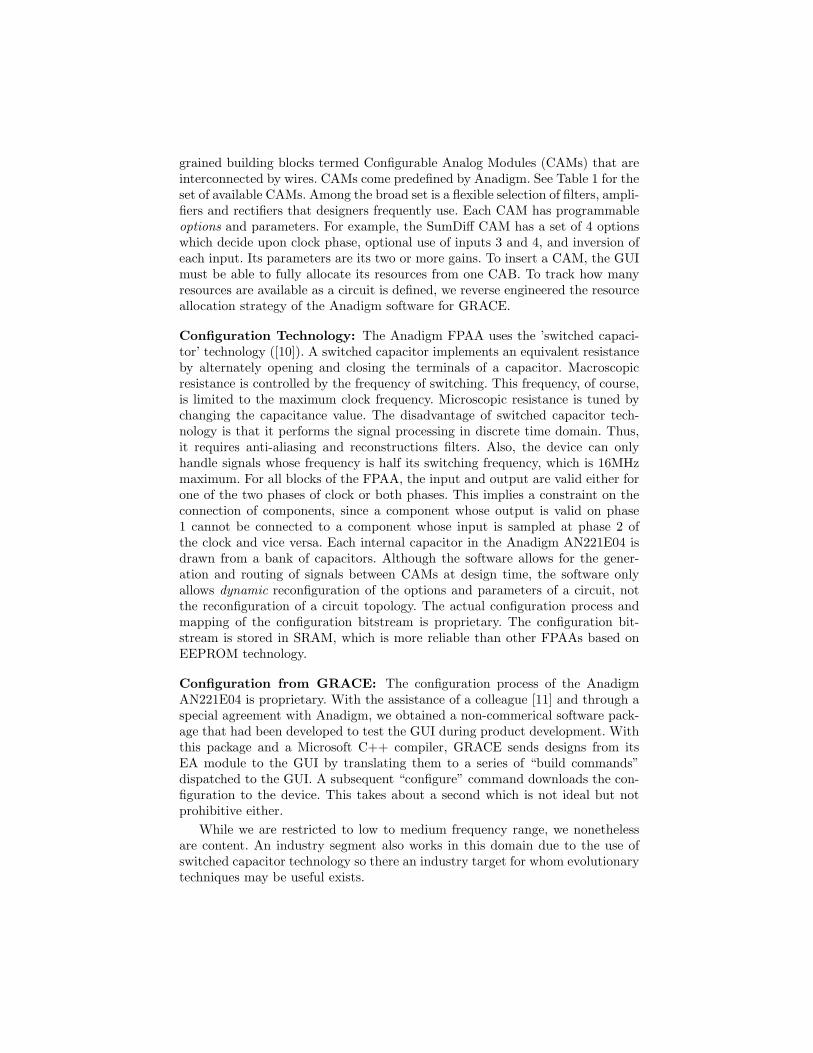
grained building blocks termed Configurable Analog Modules (CAMs) that areinterconnected by wires. CAMs come predefined by Anadigm. See Table 1 for theset of available CAMs. Among the broad set is a flexible selection of filters, ampli-fiers and rectifiers that designers frequently use. Each CAM has programmableoptions and parameters. For example, the SumDiff CAM has a set of 4 optionswhich decide upon clock phase, optional use of inputs 3 and 4, and inversion ofeach input. Its parameters are its two or more gains. To insert a CAM, the GUImust be able to fully allocate its resources from one CAB. To track how manyresources are available as a circuit is defined, we reverse engineered the resourceallocation strategy of the Anadigm software for GRACE.
Configuration Technology: The Anadigm FPAA uses the ’switched capaci-tor’ technology ([10]). A switched capacitor implements an equivalent resistanceby alternately opening and closing the terminals of a capacitor. Macroscopicresistance is controlled by the frequency of switching. This frequency, of course,is limited to the maximum clock frequency. Microscopic resistance is tuned bychanging the capacitance value. The disadvantage of switched capacitor tech-nology is that it performs the signal processing in discrete time domain. Thus,it requires anti-aliasing and reconstructions filters. Also, the device can onlyhandle signals whose frequency is half its switching frequency, which is 16MHzmaximum. For all blocks of the FPAA, the input and output are valid either forone of the two phases of clock or both phases. This implies a constraint on theconnection of components, since a component whose output is valid on phase1 cannot be connected to a component whose input is sampled at phase 2 ofthe clock and vice versa. Each internal capacitor in the Anadigm AN221E04 isdrawn from a bank of capacitors. Although the software allows for the gener-ation and routing of signals between CAMs at design time, the software onlyallows dynamic reconfiguration of the options and parameters of a circuit, notthe reconfiguration of a circuit topology. The actual configuration process andmapping of the configuration bitstream is proprietary. The configuration bit-stream is stored in SRAM, which is more reliable than other FPAAs based onEEPROM technology.
Configuration from GRACE: The configuration process of the AnadigmAN221E04 is proprietary. With the assistance of a colleague [11] and through aspecial agreement with Anadigm, we obtained a non-commerical software pack-age that had been developed to test the GUI during product development. Withthis package and a Microsoft C++ compiler, GRACE sends designs from itsEA module to the GUI by translating them to a series of “build commands”dispatched to the GUI. A subsequent “configure” command downloads the con-figuration to the device. This takes about a second which is not ideal but notprohibitive either.
While we are restricted to low to medium frequency range, we nonethelessare content. An industry segment also works in this domain due to the use ofswitched capacitor technology so there an industry target for whom evolutionarytechniques may be useful exists.
CAM CAM CAM
Voltage Transfer Function Inverting Differentiator Divider
Half cycle inverting Gain Stage Biquadratic Filter Half Cycle Gain Stage
Half Cycle Sum/Difference Stage DC Voltage Source Inverting Gain Stage
Gain Stage: Switchable inputs Bilinear Filter Integrator
Gain Stage: Polarity Control Half Cycle Rectifier Half Cycle Gain Stage
Gain Stage - Output V Limiting Inverting Sum Stage Multiplier
Rectifier with Low Pass Filter Sample & Hold Sinewave Oscillator
Transimpedance Amplifier Waveform Generator
Table 1. Anadigm AN221E04 CAMs
3 GRACE: The system
GRACE is depicted in Figure 2 which shows an adaptive controller on the FPAAthat controls a third order plant. The evolutionary algorithm (EA) runs on anPentium P4 machine. It reconfigures the Anadigm AN221E04 to build new con-trollers, evaluate their efficiency in controlling the plant and thus guide the searchto find better controllers. A summary of the components is given in Table 2.
EHW@CSAIL
Controller
ConfigurationEvolutionary
Algorithm
-
PLANT
Configured
Controller
FPAA
SRAM
Vin
Vout
Vreft
DAQ
serial
Fig. 2. GRACE Architecture.
The Anadigm AN221E04 is configured by the EA via the serial port. The EAsends inputs to the hardware and extract outputs via National Instrument’s PCI-6221 multifunction data acquisition card (DAQ). (The PCI-6221 DAQ boardprovides up to 80 analog inputs and 4 analog outputs giving GRACE scalabil-ity). The DAQ provides both analog to digital and digital to analog conversionwith 16-bit resolution (for a voltage range of -10V to 10V). The reference signalto the testbench is specified by the algorithm to the DAQ as a digital waveform.The DAQ converts it to an analog signal and sends it to the testbench. Simul-taneously, the DAQ converts the plant’s analog output signal to a digital signalfor the evolutionary algorithm to compare with the reference signal. Our sys-tem actually duplicates the reference signal sent to the controller to be matchedwith the plant output. This yields a time synchronized comparison between thereference and plant signals.
Component Specifications Procured From Price
Dell Dimension 8400 3.6GHz P4 CPU, 2GBRAM
Dell Computers $2200 + costof monitor
FPAA DevelopmentKit
PCB with FPAA and 2Signal Conditioning Dual-opamps
NI 6221 DAQ Multifunction DAQ withanalog output, PCI Card
National Instru-ments
$430
NI Connect Block andCable
Shielded Connection Blockwith Cable to Interface toPCI DAQ card
National Instru-ments
$350
Table 2. GRACE: System Components, specifications, sources and cost.
4 Choosing a Genetic Representation
The genetic representations of the evolvable hardware community have rangedfrom directly expressing the configuration bitstream to expressing a circuit com-ponent representation. A prominent example of the first extreme are the projectsby A. Thompson [12] and his co-authors who used the Xilinx 6216. At the otheris the “circuit constructing tree” which is a developmental encoding, e.g. [13]. Incontrast, in GRACE a subset of the Anadigm CAM’s are the functions in thesense of genetic programming. All CAMs with valid output for only one of theclock phases had their outputs connected to a ”Sample and Hold” component.The GRACE genome is a cyclic graph (see Figure 3) in which each node is aninstance of a CAM and directional links define the topology. A circuit has avariable number of CAMs but we implement the graph as a fixed length vector.Each element of the vector is a structure which specifies a CAM, its options,parameters and input source(s). Each instance of a CAM has a variable numberof programmable options and parameters. For example, the SumDiff CAM has 4options and 2 gain parameters while the simple “Half cycle Gain Stage” has only2 options and 1 gain parameter. The genome stores in each structure anothertwo vectors of data that the genome-to-circuit translation process interprets asparameters and options. Each vector is a fixed length. If the parameters andattributes of the CAM are fewer than the vector length, the extra values areignored. Like the redundant nodes and links of the circuit which do not connectinput to output, this redundant information is maintained in the genome.
The encoding of coarse grained components in the genome makes GRACEreminiscent of Koza’s genetic programming tree representation, e.g. in [14]. Theobvious difference is the cyclic graph versus the tree. Another difference is thegenome length – fixed in GRACE’s case and variable in Koza’s. The physicallimitation of resource quantities on the device demand that GRACE not evolvea genome that requires more resources than on the device. This is ensured by
C
Type: gain_inv
Parms[1.1,0.4]
Options:{0,0,1,1}
Inputs [!2]
Type: sumDiff2*
Parms: [0.05,0.1]
Options:{1,0,1,1}
Inputs [I1,I2]-G
!2
!3
-G
!2
!3
I1
I2
I2!
!C
Type: gain_inv
Parms[1.1,0.4,0.0,0.1]
Options:{0,0,1,1}
Inputs [!2]
Type: sumDiff2*
Parms: [0.05,0., 0.0, 0.01]
Options:{1,0,1,1}
Inputs [I1,I2]-G
!2
!3
-G
!2
!3
I1
I2
I2!
!
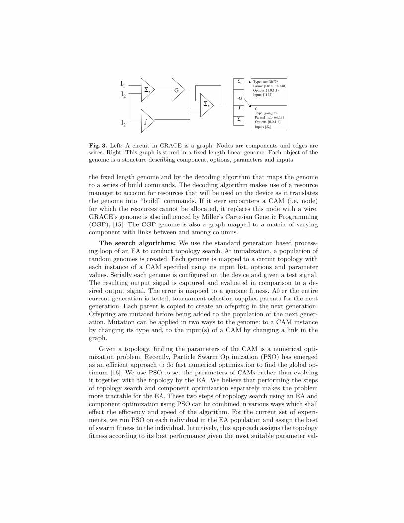
Fig. 3. Left: A circuit in GRACE is a graph. Nodes are components and edges arewires. Right: This graph is stored in a fixed length linear genome. Each object of thegenome is a structure describing component, options, parameters and inputs.
the fixed length genome and by the decoding algorithm that maps the genometo a series of build commands. The decoding algorithm makes use of a resourcemanager to account for resources that will be used on the device as it translatesthe genome into “build” commands. If it ever encounters a CAM (i.e. node)for which the resources cannot be allocated, it replaces this node with a wire.GRACE’s genome is also influenced by Miller’s Cartesian Genetic Programming(CGP), [15]. The CGP genome is also a graph mapped to a matrix of varyingcomponent with links between and among columns.
The search algorithms: We use the standard generation based process-ing loop of an EA to conduct topology search. At initialization, a population ofrandom genomes is created. Each genome is mapped to a circuit topology witheach instance of a CAM specified using its input list, options and parametervalues. Serially each genome is configured on the device and given a test signal.The resulting output signal is captured and evaluated in comparison to a de-sired output signal. The error is mapped to a genome fitness. After the entirecurrent generation is tested, tournament selection supplies parents for the nextgeneration. Each parent is copied to create an offspring in the next generation.Offspring are mutated before being added to the population of the next gener-ation. Mutation can be applied in two ways to the genome: to a CAM instanceby changing its type and, to the input(s) of a CAM by changing a link in thegraph.
Given a topology, finding the parameters of the CAM is a numerical opti-mization problem. Recently, Particle Swarm Optimization (PSO) has emergedas an efficient approach to do fast numerical optimization to find the global op-timum [16]. We use PSO to set the parameters of CAMs rather than evolvingit together with the topology by the EA. We believe that performing the stepsof topology search and component optimization separately makes the problemmore tractable for the EA. These two steps of topology search using an EA andcomponent optimization using PSO can be combined in various ways which shalleffect the efficiency and speed of the algorithm. For the current set of experi-ments, we run PSO on each individual in the EA population and assign the bestof swarm fitness to the individual. Intuitively, this approach assigns the topologyfitness according to its best performance given the most suitable parameter val-
ues. Other approaches which trade speed for efficiency and vice-versa are understudy.
5 GRACE in Action: Evolving a Controller
We have initially used GRACE to evolve a controller for the simple first orderplant shown in Figure 4 (left). The plant has bandwidth of 338.6Hz and a steadystate gain of 2.5. The CAMs in the primitive set for the given problem canbe found in Table 3 along with their respective parameters and options. TheseCAMs are capable of creating any transfer function (realizable given the capacityof the FPAA) including the ubiquitous Proportional-Integral-Differential control.The population size was 15 with tournament selection of size 3 and elitism for3 individuals. A run was 10 generations with the probability of mutating aCAM 0.45 and a wire 0.45. The PSO ran 6 iterations every generation on everyindividual with a swarm size of 4.
Fitness Function Though a simple step function would seem to be all thatis required to evaluate a controller, we used a more complex signal to ensure thatGRACE did not evolve a signal generator regardless of the input. The signal anda candidate circuit’s response is shown on the right in Figure 4. The signal hassix voltage levels (-1.5V, -0.75V, -0.375, 0.375, 0.75V. and 1.5V) and changesstate every 4.16ms. We sampled the signal at 125 KHz. The fitness of a circuitis the weighted sum of squared errors between the circuit’s output signal andthe test signal. The fitness function weights can be tuned to trade-off criteria ofsettling time, peak overshoot and steady state error. For instance, more weightto the error in latter part of the step response shall bias the search towardscontrollers with lower steady state error and shall care less for rise time andpeak overshoot. For the current set of experiments, we used the time-weightedleast squares, which increases the weights linearly with time. It is postulated in[17], such a fitness function is ideal for judging the efficiency of a controller.
Evolved Solutions The system evolved solutions with high fitness value(validated by visual inspection of generated waveforms) that instantiate variouscontrol strategies, for instance, proportional control, integral control or lossyintegral control. Evolution also found interesting ways to build solutions, likeuse of a differentiator in feedback to evolve a lossy integrator and using multiplefeedback to realize different gains (including high gain through positive feedback)for proportional control.
Analysis of one of the best-of-run controller showed how evolution can thinkout-of-the-box. Figure 5 shows the controller as seen in the Anadigm GUI on theleft and the equivalent simple block diagram on the right. Simple hand-analysisshows that the solution is a filter. The summing-integrator filter topology isa well-known approach to synthesize filters. It is counter-intuitive why a filterwould be a good controller. Evolution exploits the high integration-constant (ofthe order of Mega per second) realizable by the integrator. It evolves a highgain filter with a large bandwidth that has an integrator in both the forwardand feedback paths. This effectively behaves like proportional control with a
large gain. The high gain of the P-control reduces the steady-state error thuscontributing to high fitness. This solution has not been included in discussion forits usefulness in a real scenario, but due to illustrate the ability of algorithm tosynthesize interesting topologies and the capability of evolution to explore realmsof unconventional design even when it uses coarse-grained building blocks.
Work is underway to study the solutions generated and use a carefully craftedfitness function to better capture the characteristics of the controller. With aneffective fitness function instantiated in the system, we shall determine the use-fulness of the circuits evolved and compare them with those evolved on otherplatforms such as the FPTAs. We also plan to study how variation in the evolu-tionary algorithm (method/parameters) affects its ability to search for a solutionin the given problem domain.
CAM Parameter(s) # In
SumDiff-2* inputs gain value(s) 2
SumDiff-3* inputs gain value(s) 3
Inverting Differentiator diff. constant (us) 1
Integrator gain 1
Gain Inverter gain 1
Gain* gain 1
Wire 0 1Table 3. CAMs used in the GRACE Function Set for Controller Evolution. Asteriskindicates output is connected to sample and hold block for two clock phase results.
Fig. 4. Left: Plant for evolved controller, Right: Fitness function test signal (squarewave) with example circuit’s output signal for the controller experiment.
6 Summary
By combining the exploitation of coarse grained elements with intrinsic testingon a COTS device, we think GRACE comprises a distinctive approach to analogEHW. This paper’s goal has been to elucidate our decision process in engineeringGRACE. We feel our decision to use the Anadigm AN221E04 forges GRACE’s
Fig. 5. Left: An evolved filter solution displayed from GUI , Right: Schematic of samesolution.
identity. It is a COTS rather than custom device. The proprietary nature ofits configuration process can be circumvented for practicality. It uses SRAMto hold a configuration. This makes it suited as a component of an adaptive,fault tolerant system. It exploits switched capacitor technology. This allows itsevolved designs to conform with industry specifications and be realizable. Thiswill facilitate the ultimate placement of evolved circuits in the field.
Finally, in using the Anadigm AN221E04, it offers coarse grained elements.Coarse granularity makes GRACE contrast with FPTA approaches by exchang-ing flexibility with higher level building block abstraction. We think that GRACEenables a parallel set of investigations that will provide interesting comparisonsbetween the non-linear design space of the FPTA and the human oriented, con-ventional design space. We believe our choices additionally provide us with trac-tion into both adaptive, robust hardware evolution and the more traditionalpursuit of analog CAD. This will be the direction of our future research usingGRACE.
Acknowledgements
We would like to thank Anadigm, Dimitri Berensen, Garrison Greenwood, DavidHunter, Didier Keymeulen, Adrian Stoica, and Eduardo Torres-Jara for theircontributions to the development of GRACE.
References
1. Stoica, A., Zebulum, R.S., Keymeulen, D.: Progress and challenges in buildingevolvable devices. In: Evolvable Hardware. (2001) 33–35
2. Greenwood, G., Hunter, D.: Fault recovery in linear systems via intrinsic evolution.In Zebulum, R., Gwaltney, D., Hornby, G., Keymeulen, D., Lohn, J., Stoica, A.,eds.: Proceedings of the NASA/DoD Conference on Evolvable Hardware, Seattle,Washington, IEEE Computer Society (2004) 115–122
4. Stoica, A., Zebulum, R., Keymeulen, D., Tawel, R., Daud, T., Thakoor, A.: Re-configurable vlsi architectures for evolvable hardware: from experimental field pro-grammable transistor arrays to evolution-oriented chips. IEEE Transactions onVLSI Systems, Special Issue on Reconfigurable and Adaptive VLSI Systems 9(1)(2001) 227–232
5. Stoica, A., Zebulum, R.S., Keymeulen, D.: Polymorphic electronics. In Liu, Y.,Tanaka, K., Iwata, M., Higuchi, T., Yasunaga, M., eds.: ICES. Volume 2210 ofLecture Notes in Computer Science., Springer (2001) 291–302
6. Keymeulen, D., Stoica, A., Zebulum, R.: Fault-tolerant evolvable hardware usingfield programmable transistor arrays. IEEE Transactions on Reliability, SpecialIssue on Fault-Tolerant VLSI Systems 49(3) (2000) 305–316
7. Stoica, A., Keymeulen, D., Zebulum, R.S.: Evolvable hardware solutions for ex-treme temperature electronics. In: Evolvable Hardware, IEEE Computer Society(2001) 93–97
8. Langeheine, J., Becker, J., Folling, S., Meier, K., Schemmel, J.: Initial studies ofa new vlsi field programmable transistor array. In Liu, Y., Tanaka, K., Iwata, M.,Higuchi, T., Yasunaga, M., eds.: Evolvable Systems: From Biology to Hardware:Proceedings of 4th International Conference, ICES 2001. Volume 2210 of LectureNotes in Computer Science., Tokyo, Japan, Springer-Verlag (2001)
9. Stoica, A., Zebulum, R., Ferguson, M., Keymeulen, D., Duong, V.: Evolving cir-cuits in seconds: Experiments with a stand-along board-level evolvable system. InStoica, A., Lohn, J., Katz, R., Keymeulen, D., Zebulum, R.S., eds.: Proceedings ofthe NASA/DoD Conferenece on Evolvable Hardware, Alexandria, Virginia, IEEEComputer Society (2002) 129–130
11. Berenson, D.: Personal communication. email: January 18, 2005 (2005)12. Thompson, A.: Hardware Evolution: Automatic design of electronic circuits in
reconfigurable hardware by artificial evolution. Springer-Verlag (1998)13. Koza, J.R., Bennett III, F.H., Andre, D., Keane, M.A.: Four problems for which
a computer program evolved by genetic programming is competitive with humanperformance. In: Proceedings of the 1996 IEEE International Conference on Evo-lutionary Computation. Volume 1., IEEE Press (1996) 1–10
15. Miller, J.F., Thompson, P.: Cartesian genetic programming. In: Proceedings ofThird European Conference on Genetic Programming, Springer-Verlag (2000) 121–132
16. Kennedy, J., Eberhart, R.: Particle swarm optimization. In: Proceedings of theFourth IEEE International Conference on Neural Networks, IEEE Press (1995)
17. Krohling, R.A., Jaschek, H., Rey, J.: Designing PI/PID controllers for a motioncontrol system based on genetic algorithms. In: Proceedings of the 12th IEEEInternational Symposium on Intelligent Control. (1997) 125–130