` Province of the EASTERN CAPE EDUCATION NATIONAL SENIOR CERTIFICATE GRADE 11 NOVEMBER 2012 MECHANICAL TECHNOLOGY MARKS: 200 TIME: 3 hours This paper consists of 21 pages including an answer sheet and 2-page formula sheet. *MCHTDM*
Transcript
`
Province of the
EASTERN CAPE EDUCATION
NATIONAL SENIOR CERTIFICATE
GRADE 11
NOVEMBER 2012
MECHANICAL TECHNOLOGY
MARKS: 200
TIME: 3 hours
This paper consists of 21 pages including an answer sheet and 2-page formula sheet.
*MCHTDM*
2 MECHANICAL TECHNOLOGY (NOVEMBER 2012)
INSTRUCTIONS AND INFORMATION 1. Write your name and surname number in the spaces provided on the
answer book.
2. Answer ALL the questions. 3. Read ALL the questions carefully. 4. Number and answer according to the numbering system used in the
questions.
5. Write neatly and legibly. 6. Show all calculations and units. 7. Candidates may use non-programmable scientific calculators and
drawing/mathematical instruments.
8. The value of the gravitational force should be taken as 10 m/s2. 9. Use the criteria below to assist you in managing your time.
Question Assessment Standards
Concepts covered Marks Time
1 1 – 9 Multiple-choice questions 20 18 minutes
2 6 and 8 Applied Mechanics 50 45 minutes
3 2 Tools and equipment 20 18 minutes
4 3 Materials 20 18 minutes
5 1, 4 and 5 Manufacturing process, construction methods and safety
50 45 minutes
6 7 and 9 Pumps and maintenance 40 36 minutes
Total 200 180 minutes
(NOVEMBER 2012) MECHANICAL TECHNOLOGY 3
QUESTION 1: MULTIPLE-CHOICE QUESTIONS Various options are provided as possible answers to the following questions. Choose the answer and make a cross (X) in the block (A – D) next to the question number (1.1 – 1.20) on the attached ANSWER SHEET.
EXAMPLE: 1.21 A B C D
1.1 Which ONE of the following is NOT a safety device which is used at a
guillotine?
A Fixed guard B Automatic sweep-away or push-away guard C Freestanding guard D Self-adjusting guard (1) 1.2 What needs to be taken into account when working with a hydraulic
press? Which ONE does NOT fit?
A That the predetermined pressure may be exceeded for a short
period of time.
B That the platform must be rigid and square with the cylinder of the press.
C That the platform must rest on the supports provided. D That all the bolts and nuts are tightened on the apparatus. (1) 1.3 At which temperature is the gauge blocks most accurate? A 19 °Celsius B 20 °Celsius C 36 °Celsius D 26 °Celsius (1)
4 MECHANICAL TECHNOLOGY (NOVEMBER 2012)
1.4 FIGURE 1.4 shows a sine bar used in conjunction with other instruments.
What is the application of the sine bar?
FIGURE 1.4 A To set out various angles. B To test the accuracy of a work piece. C A and B. D None of the above-mentioned. (1) 1.5 How can we prevent incomplete or spotty hardening of steel, during liquid
quenching in baths?
A Either the quenching medium or steel being quenched should be
agitated (moved around).
B Increase the cooling rate. C Prevent the cooling liquid from boiling. D Increase the timeframe/period when quenching. (1) 1.6 Which method is NOT a case-hardening method? A Carburising B Cyaniding C Nitriding D Oil hardening (1) 1.7 The metric measurement system uses … A inches measurement for length. B millimetre measurements for length. C foot measurements for length. D yard measurements for length (1)
(NOVEMBER 2012) MECHANICAL TECHNOLOGY 5
1.8 Study the sketch of a turning procedure which can be carried out on a
lathe. Which of the answers below represents the procedure in the sketch?
FIGURE 1.8 A Internal taper turning B External turning C Taper turning between centres D Screw cutting (1) 1.9 Identify the type of welding joint shown in FIGURE 1.9.
FIGURE 1.9 A Corner joint B Lap joint C Butt joint D T-joint (1)
6 MECHANICAL TECHNOLOGY (NOVEMBER 2012)
1.10 Which welding position is illustrated in FIGURE 1.10?
FIGURE 1.10 A Flat position B Overhead position C Oblique position D Horizontal position (1) 1.11 What concept describes “tie” the best? A Pulling force B Shearing force C Pushing force D Tearing force (1) 1.12 What type of lathe method is shown in FIGURE 1.12?
FIGURE 1.12 A Groove cutting B Facing C Thread cutting D Boring (1)
(NOVEMBER 2012) MECHANICAL TECHNOLOGY 7
1.13 Failure of an engine cooling system is an obvious cause of … A inadequate lubrication. B inadequate maintenance. C inadequate cooling. D none of the above-mentioned. (1) 1.14 What will happen if the engine oil in a vehicle becomes too dirty? A The oil canals will become blocked. B The dirty oil circulates and promotes further wear. C The oil cannot disperse heat effectively. D All the above-mentioned. (1) 1.15 What is the purpose of the non-return valve? A To lower the pressure in the system. B To allow only a certain amount of oil through. C To allow flow in one direction. D A and C. (1) 1.16 Which component in the ABS-braking system detects when a wheel
starts to spin on a wet, icy or slippery surface?
A Hydraulic control valve/unit. B Electric control unit. C Wheel speed sensor D Microprocessor. (1) 1.17 What is the purpose of the strainer in an oil pump? A Prevents the pump from drawing dirt. B Increases the pressure of the pump. C Increases the volume of the oil inside the pump casing. D Decrease the thickness of the oil in the pump system. (1)
8 MECHANICAL TECHNOLOGY (NOVEMBER 2012)
1.18 Which of the following descriptions represents the pump as shown in
FIGURE 1.18?
FIGURE 1.18 A Vane pump B Centrifugal pump C Rotor pump D Gear pump (1) 1.19 Which of the following gear systems will be suitable for the operation of
an electronic sliding gate?
A Rack and Pinion system B Worm gear system C Spur gear system D Helical gear system (1) 1.20 FIGURE 1.20 shows a beam with two loads. Determine the distance of
load B from the fulcrum in order to balance the beam.
FIGURE 1.20 A 8 m B 6 m C 4 m D 2 m (1) [20]
(NOVEMBER 2012) MECHANICAL TECHNOLOGY 9
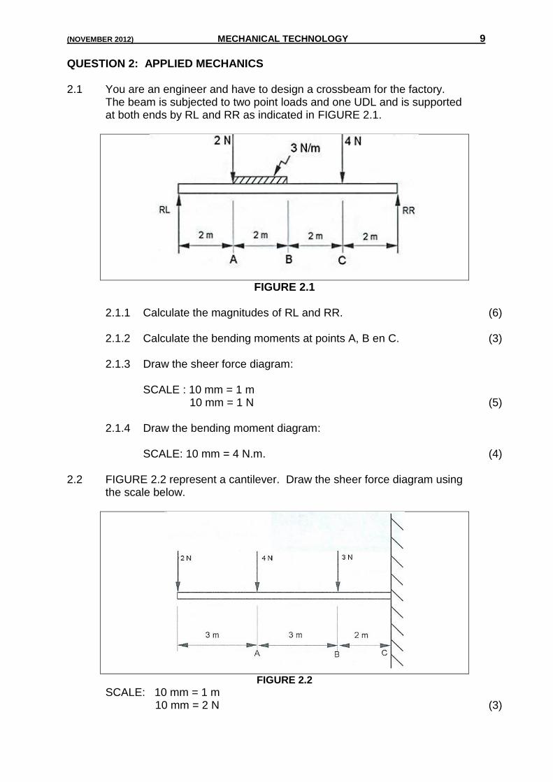
QUESTION 2: APPLIED MECHANICS 2.1 You are an engineer and have to design a crossbeam for the factory.
The beam is subjected to two point loads and one UDL and is supported at both ends by RL and RR as indicated in FIGURE 2.1.
FIGURE 2.1
2.1.1 Calculate the magnitudes of RL and RR. (6) 2.1.2 Calculate the bending moments at points A, B en C. (3) 2.1.3 Draw the sheer force diagram:
SCALE : 10 mm = 1 m 10 mm = 1 N (5)
2.1.4 Draw the bending moment diagram:
SCALE: 10 mm = 4 N.m. (4)
2.2 FIGURE 2.2 represent a cantilever. Draw the sheer force diagram using
the scale below.
FIGURE 2.2
SCALE: 10 mm = 1 m 10 mm = 2 N (3)
10 MECHANICAL TECHNOLOGY (NOVEMBER 2012)
2.3 The figure shows different types of gears. Identify the different type of
gears.
A B
C D (4)
2.4 Screw threads are fundamental to industrial progress, being used for
hundreds of different functions. The following is an external screw thread which can be manufactured by cutting on the lathe/milling machine. Analyse and label the screw thread from A – H.
(8)
(NOVEMBER 2012) MECHANICAL TECHNOLOGY 11
2.5 Name the THREE categories clutches can be divided into. (3) 2.6 Which part is driven by the clutch plate? (1) 2.7 In which class lever will you classify the wheelbarrow as shown in
FIGURE 2.5? (1)
FIGURE 2.5
2.8 The cam mechanism is commonly used to operate valves in motor vehicle engines. Name the THREE parts of the cam mechanism. (3)
2.9 Identify the pneumatic and hydraulic symbols as shown below:
A B C (3)
2.10 What does the abbreviation ABS denotes, or stands for? (1) 2.11 Valves play an important role in hydraulic and pneumatic systems.
Write down THREE functions of valves in a hydraulic or pneumatic system. (3)
2.12 Modern motor vehicles are fitted with fuel injection systems. The
injector nozzles can be mounted in two places. Name the TWO places. (2)
[50]
12 MECHANICAL TECHNOLOGY (NOVEMBER 2012)
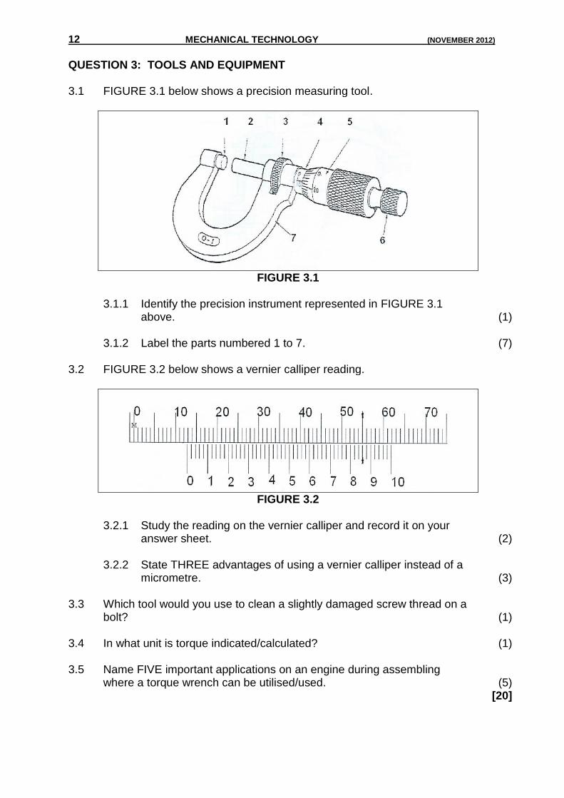
QUESTION 3: TOOLS AND EQUIPMENT 3.1 FIGURE 3.1 below shows a precision measuring tool.
FIGURE 3.1 3.1.1 Identify the precision instrument represented in FIGURE 3.1
above. (1) 3.1.2 Label the parts numbered 1 to 7. (7) 3.2 FIGURE 3.2 below shows a vernier calliper reading.
FIGURE 3.2 3.2.1 Study the reading on the vernier calliper and record it on your
answer sheet. (2) 3.2.2 State THREE advantages of using a vernier calliper instead of a
micrometre. (3) 3.3 Which tool would you use to clean a slightly damaged screw thread on a
bolt? (1) 3.4 In what unit is torque indicated/calculated? (1) 3.5 Name FIVE important applications on an engine during assembling
where a torque wrench can be utilised/used. (5) [20]
(NOVEMBER 2012) MECHANICAL TECHNOLOGY 13
QUESTION 4: MATERIALS 4.1 Explain the term, “heat treatment”. (3) 4.2 A hardness test is a means of determining resistance to penetration.
This is one way of determining hardness. Name the other TWO ways in which hardness is measured. (2)
4.3 Tabulate the following heat treatment processes and identify ONE
property and its quenching media.
Processes Property Media
4.3.1 Hardening (2)
4.3.2 Tempering (2)
4.3.3 Annealing (2)
4.3.4 Normalising (2)
4.4 Due to non-availability of hardness equipment or machine at your
school; you are required to demonstrate an engineering activity which is to conduct an indentation test. The following tools and metal been given to you.
1. One piece of aluminium (soft metal) 2. Alloy tool steel (hard metal) 3. Ball peen hammer 4. Centre punch Explain the method/procedure of your demonstration and findings/
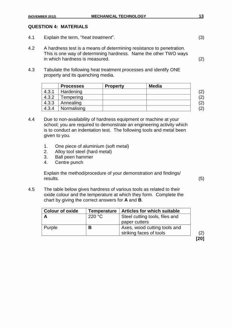
results. (5) 4.5 The table below gives hardness of various tools as related to their
oxide colour and the temperature at which they form. Complete the chart by giving the correct answers for A and B.
Colour of oxide Temperature Articles for which suitable
A 220 °C Steel cutting tools, files and paper cutters
Purple B Axes, wood cutting tools and striking faces of tools (2)
[20]
14 MECHANICAL TECHNOLOGY (NOVEMBER 2012)
QUESTION 5: MANUFACTURING PROCESS, CONSTRUCTION AND SAFETY 5.1 You must drill holes in a work piece using a drill press. Name FIVE safety
rules to be observed during the use of the drill press. (5) 5.2 You must cut a 50 mm solid round bar using the power saw. Identify FOUR
safety rules when using the power saw. (4) 5.3 Name FOUR safety precautions to follow when working with a milling
machine. (4) 5.4 Your teacher instructed you to braze two metal pieces together. First you
need to explain the preparation processes, which will assist the brazing filler material in making a bond. (2)
5.5 5.5.1 Name any FIVE turning operations that can be executed on a centre
lathe. (5) 5.5.2 Identify the sectional view of a lathe, by labelling the components
from A – E.
(5)
5.6 When working on a centre lathe, cutting tools and tool holders plays an
important role in the efficient and smooth cutting action of material. Name FOUR precautionary measures that need to be adhere to for an efficient and smooth cutting action. (4)
(NOVEMBER 2012) MECHANICAL TECHNOLOGY 15
5.7 What is the meaning of the welding symbol, as indicated in FIGURE 5.7?
(2)
FIGURE 5.7 5.8 Complete the following: 5.8.1 Give the symbol for pressure, stress (1) 5.8.2 Give the symbol for area (1) 5.8.3 Give the symbol for speed, velocity (1) 5.8.4 Seven kilometre = … metre (convert) (1) 5.8.5 Give the meaning of RPM. (1) 5.9 5.9.1 Describe in SIX steps how the start-up (ignite) procedure will work
for the oxy-acetylene apparatus. (6) 5.9.2 Which gas bottle uses a left-hand screw thread? (1) 5.9.3 What does it mean to sniff a cylinder? (1) 5.10 Identify the following welding symbols. Make a neat sketch to explain how
each welding joint will be applicable in practice.
5.10.1
(2) 5.10.2
(2) 5.10.3
(2) [50]
16 MECHANICAL TECHNOLOGY (NOVEMBER 2012)
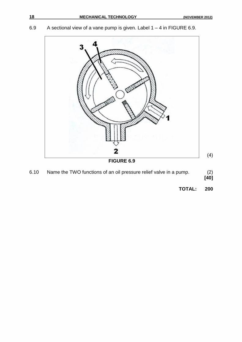
QUESTION 6: PUMPS AND MAINTENANCE
6.1 In mechanical components friction can never be completely eliminated, but can be drastically reduced by using suitable lubricants. Answer the following questions.
6.1.1 What is the purpose of any lubricant? (1)
6.1.2 What does the term friction mean? (1)
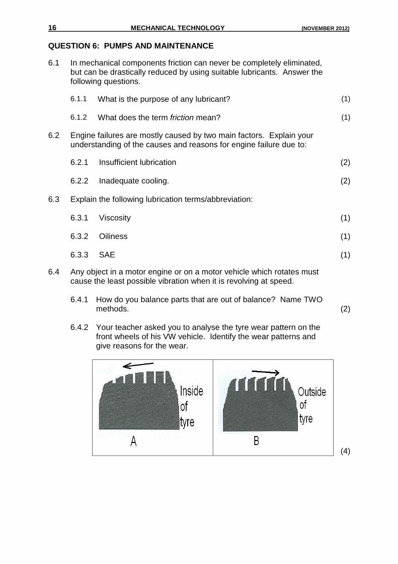
6.2 Engine failures are mostly caused by two main factors. Explain your understanding of the causes and reasons for engine failure due to: