GRAFIK Eye ® Window Treatments GRAFIK Eye 3000 SYSTEM MAP (SHOWN) • Use the map at right to identify system component being reviewed in each section • For overall wiring information, see pgs. 24 and 34 SPECIFICATIONS GRAFIK Eye 3000/4000 Sivoia QED Controller (SG-SVCN) must be used with one of the following GRAFIK Eye model numbers: GRX-350X-X-XX-CPN1622 or GRX-450X-X-XX-CPN1623 • Power: 24VAC (Supplied by Sivoia QED Electronic Drive Unit) • Wiring Specifications: Connects to both GRAFIK Eye and Sivoia QED communication links: - to GRAFIK Eye 3000 Series: (2) twisted pair #18 AWG (1.0mm 2 ) plus wiring to Sivoia QED EDU - to GRAFIK Eye 4000 Series: (2) #12 AWG (2.5mm 2 ), (1) twisted, shielded pair #18 AWG (1.0mm 2 ), plus (1) #18 AWG (1.0mm 2 ), plus wiring to Sivoia QED EDU - to Sivoia QED EDU: (3) #18 AWG (1.0mm 2 ) [24VAC, plus earth ground] and (1) twisted, shielded pair #22 AWG (1.0mm 2 ) • Mounting: Standard US wallbox; no derating required when multiganged AC Motor Group Controller (GRX-4M-GC) must be used with one of the following GRAFIK Eye model numbers: GRX-350X-X-XX-CPN1622 or GRX-450X-X-XX-CPN1623 • Power: 110-127 VAC, 50-60 Hz • Channel Capacity: 4 channels each at 5 A, 1/4 HP motor load per channel at 120 VAC; 20 A total input current • Mounting: Must be accessible for programming and setup - Wall-mounted; allow 4.5” (114mm) between Group Controllers when mounting multiple units - Unit’s relays will click in normal use; mount where this is acceptable www.lutron.com Lutron World Headquarters: 1.610.282.3800 Standards listed below apply to one or more products in the GRAFIK Eye product line. Consult factory for specific information. LUTRON Quality Systems registered to ISO 9001 Sivoia QED Controller AC Motor Group Controller Sources Controllable Window Treatments Window Treatment Controllers and Wallstations • Used to incorporate Sivoia QED™ and AC motorized projection screens/shades and draperies into scenes, or control independently from GRAFIK Eye Control Units or seeTouch wallstations • Up to total of 8 Window Treatment Controllers (Sivoia QED Controllers plus AC Motor Group Controllers) can be in one system with 8 GRAFIK Eye Control Units and 16 Control Station Devices (includes Window Treatment Wallstations) • Must be used with one of the following GRAFIK Eye model numbers: GRX-350X-X-XX-CPN1622, pg. 27 or GRX-450X-X-XX-CPN1623, pg. 37 • Requires a dedicated zone on the GRAFIK Eye Control Unit for each independent Window Treatment, screen, shade, or drapery zone GRAFIK Eye Window Treatments 66
Transcript
GRAFIK Eye® Window Treatments
GRAFIK Eye 3000SYSTEM MAP (SHOWN)• Use the map at right to identify system
component being reviewed in each section
• For overall wiring information, see pgs. 24 and 34
SPECIF ICATIONS
GRAFIK Eye 3000/4000 Sivoia QED Controller (SG-SVCN) must be used with one of the following GRAFIK Eye model numbers: GRX-350X-X-XX-CPN1622 or GRX-450X-X-XX-CPN1623• Power: 24VAC (Supplied by Sivoia QED Electronic Drive Unit)• Wiring Specifications: Connects to both GRAFIK Eye and Sivoia QED communication links:
- to GRAFIK Eye 3000 Series: (2) twisted pair #18 AWG (1.0mm2) plus wiring to Sivoia QED EDU- to GRAFIK Eye 4000 Series: (2) #12 AWG (2.5mm2), (1) twisted, shielded pair #18 AWG (1.0mm2),
plus (1) #18 AWG (1.0mm2), plus wiring to Sivoia QED EDU- to Sivoia QED EDU: (3) #18 AWG (1.0mm2) [24VAC, plus earth ground] and
(1) twisted, shielded pair #22 AWG (1.0mm2)• Mounting: Standard US wallbox; no derating required when multiganged
AC Motor Group Controller (GRX-4M-GC) must be used with one of the following GRAFIK Eye model numbers: GRX-350X-X-XX-CPN1622 or GRX-450X-X-XX-CPN1623• Power: 110-127 VAC, 50-60 Hz• Channel Capacity: 4 channels each at 5 A, 1⁄4 HP motor load per channel at 120 VAC; 20 A total input current• Mounting: Must be accessible for programming and setup
- Wall-mounted; allow 4.5” (114mm) between Group Controllers when mounting multiple units- Unit’s relays will click in normal use; mount where this is acceptable
www.lutron.com Lutron World Headquarters: 1.610.282.3800
Standards listed below apply to one or moreproducts in the GRAFIK Eye product line.Consult factory for specific information.
LUTRONQuality Systems
registered to ISO 9001
Sivoia QED Controller AC Motor Group Controller
Sources
Controllable Window Treatments
Window Treatment Controllers and Wallstations• Used to incorporate Sivoia QED™ and AC motorized projection screens/shades and draperies
into scenes, or control independently from GRAFIK Eye Control Units or seeTouch wallstations• Up to total of 8 Window Treatment Controllers (Sivoia QED Controllers plus AC Motor Group
Controllers) can be in one system with 8 GRAFIK Eye Control Units and 16 Control StationDevices (includes Window Treatment Wallstations)
• Must be used with one of the following GRAFIK Eye model numbers:GRX-350X-X-XX-CPN1622, pg. 27 or GRX-450X-X-XX-CPN1623, pg. 37
• Requires a dedicated zone on the GRAFIK Eye Control Unit for each independent Window Treatment, screen, shade, or drapery zone
GR
AFI
K E
yeW
indo
w T
reat
men
ts
66
AC MOTOR GROUP CONTROLLER GRX-4M-GC3
• Must be used with one of the following GRAFIK Eye model numbers: GRX-350X-X-XX-CPN1622 or GRX-450X-X-XX-CPN1623
• Requires a dedicated zone on GRAFIK Eye Control Unit for each channel in Group Controller
• 4 channel AC Motor controller; 5A, 1/4HP motor load per channel at 120VAC• Provides capability to incorporate AC Motorized Window
Treatments or projection screens into lighting scenes• Window Treatment zones may be set to Open, Close, or Unaffected
for each and every lighting scene, including the Off scene• Can control AC Motorized Window Treatments independent of lighting scenes• Provides dry contact closure inputs for control by low voltage, dry contact
closure devices in addition to GRAFIK Eye Communications link• Provides Open, Close, and Stop terminals for contact closure
input; stop function may also be accomplished by applying Open and Close simultaneously
• Provides LED indication of last position of AC window treatments (Open, Close, Stop)
• Integrates seamlessly with GRAFIK Eye 3000/4000 controls; wires directlyinto GRAFIK Eye communications link, see Wiring Diagram, pgs. 24 and 34
• Separates low-voltage and line-voltage wiring for ease of installation
SIVOIA QED™ CONTROLLER SG-SVCN-2, 3
• Must be used with one of the following GRAFIK Eye model numbers: GRX-350X-X-XX-CPN1622 or GRX-450X-X-XX-CPN1623
• Requires a dedicated zone on GRAFIK Eye Control Unit for each Sivoia QED Controller Zone
• Provides programming and control of one group of Sivoia QED Controllable WindowTreatments; one SG-SVCN needed per group of Sivoia QED Controllable Window Treatments (up to 64 EDUs) moving together
• Provides capability to incorporate Sivoia QED into lighting scenes• Window Treatment zones may be set to Open, Close, or
Unaffected in each and every lighting scene, including the Off scene
• Can control Sivoia QED independent of lighting scenes• Pressing the Open button once will cause the window
treatments to move to their fully open position Pressing the Open button again while the window treatments are opening will stop their movement
• Pressing Preset 1, 2, or 3 once will cause the window treatments to move to that preset level. If that Preset button is pressed again while the windowtreatments are moving, the window treatments will stop
• Pressing the Close button once will cause the window treatments to move to their fully closed position. Pressing the Close button again will stop their movement
• Pressing the Raise/Lower buttons will cause the window treatments to open/close while the button is pressed
• The LEDs next to each button are used during programming and provide feedback of the current Sivoia QED preset
• Connects to both GRAFIK Eye and Sivoia QEDElectronic Drive Unit (EDU) link, see Wiring Diagram, pgs. 24 and 34
Technical Support: 1.800.523.9466…24 hours/7 days (US/CAN) To Order: 1.888.LUTRON1…8a.m.–8p.m./M-F ET (US/CAN)
GRAFIK Eye® Window Treatments
Dimensions
W: 7.90” (200mm)H: 12.00” (305mm)D: 2.75” (70mm)
Surface Mount
Source Product Model Color Suffix
Footnotes, pg. 671 Depth of wallplate and backbox. Wallplate depth is 0.31”(8mm).2 Class 2/PELV wiring.3 Counts as one of eight maximum Window Treatment Controllers.
Dimensions
W: 2.75” (70mm)H: 4.56” (116mm)D: 1.06” (27mm)1
Wallbox Size: single-gang
Ordering ExampleSG-SVCN-WHadd color/finish andengraving suffix to model #.
For choices see:www.lutron.com/seetouchMatte FinishesShips in 48 hrs.White WHIvory IVBeige BEGray GRBrown BRBlack BLGloss (NEMA)FinishesShips in 48 hrs.(Insert models only)White GWHLight Almond GLA
Satin FinishesShips in 48 hrs.• See pg. 10 for complete
color offering and suffixes.
CustomizationShips in 4-6 weeks.• See pg. 12 for multigang
wallplates, color matching,engraving/silk screening,and custom controls.
• See pg. 143 for engraving schedules.
Locking Covers• See pg. 64 for
more information.
GR
AFIK
EyeW
indow Treatm
ents-Controllers
67
CONTROLLERS
Footnotes, pg. 681 Depth includes wallplate and backbox.Wallplate depth is 0.31” (8mm).2 Insert version available for Multigang installations. For insert version use I in
place of last N in Model Number. See pg.136 for more information.3 Counts as one of 16 maximum Control Station Devices.
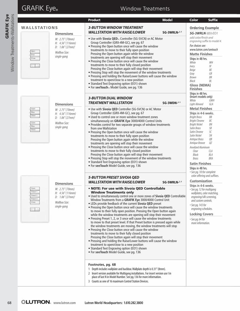
3-BUTTON WINDOW TREATMENTWALLSTATION WITH RAISE/LOWER SG-3WRLN-2, 3
• Use with Sivoia QED™ Controller (SG-SVCN) or AC Motor Group Controller (GRX-4M-GC), see pg. 67
• Pressing the Open button once will cause the window treatments to move to their fully open position Pressing the Open button again while the window treatments are opening will stop their movement
• Pressing the Close button once will cause the window treatments to move to their fully closed position Pressing the Close button again will stop their movement
• Pressing Stop will stop the movement of the window treatments• Pressing and holding the Raise/Lower buttons will cause the window
treatment to open/close to a new position• Standard Text Engraving option (EO1) shown• For seeTouch™ Model Guide, see pg. 136
• Use with Sivoia QED Controller (SG-SVCN) or AC Motor Group Controller (GRX-4M-GC), see pg. 67
• Used to control one or more window treatment zones simultaneously on GRAFIK Eye 3000/4000 Control Units
• Provides control for two separate groups of window treatments from one Wallstation
• Pressing the Open button once will cause the window treatments to move to their fully open position Pressing the Open button again while the window treatments are opening will stop their movement
• Pressing the Close button once will cause the window treatments to move to their fully closed position Pressing the Close button again will stop their movement
• Pressing Stop will stop the movement of the window treatments• Standard Text Engraving option (EO1) shown• For seeTouch Model Guide, see pg. 136
5-BUTTON PRESET SIVOIA QEDWALLSTATION WITH RAISE/LOWER SG-5WRLN-2, 3
• NOTE: For use with Sivoia QED Controllable Window Treatments only
• Used to simultaneously control one or more zones of Sivoia QED ControllableWindow Treatments from a GRAFIK Eye 3000/4000 Control Unit
• LEDs provide feedback of the current Sivoia QED preset• Pressing the Open button once will cause the window treatments
to move to their fully open position. Pressing the Open button again while the window treatments are opening will stop their movement
• Pressing Preset 1, 2, or 3 once will cause the window treatments to move to that preset level. If that Preset button is pressed again while the window treatments are moving, the window treatments will stop
• Pressing the Close button once will cause the window treatments to move to their fully closed position Pressing the Close button again will stop their movement
• Pressing and holding the Raise/Lower buttons will cause the window treatment to open/close to a new position
• Standard Text Engraving option (EO1) shown• For seeTouch Model Guide, see pg. 136
www.lutron.com Lutron World Headquarters: 1.610.282.3800
GRAFIK Eye® Window Treatments
Dimensions
W: 2.75” (70mm)H: 4.56” (116mm)D: 1.06” (27mm)1
Wallbox Size:single-gang
Dimensions
W: 2.75” (70mm)H: 4.56” (116mm)D: 1.06” (27mm)1
Wallbox Size:single-gang
Dimensions
W: 2.75” (70mm)H: 4.56” (116mm)D: 1.06” (27mm)1
Wallbox Size:single-gang
Product Model Color Suffix
GR
AFI
K E
yeW
indo
w T
reat
men
ts-W
allst
atio
ns
68
Ordering ExampleSG-3WRLN-WH-EO1add color/finish andengraving suffix to model #.
For choices see:www.lutron.com/seetouchMatte FinishesShips in 48 hrs.White WHIvory IVBeige BEGray GRBrown BRBlack BLGloss (NEMA)FinishesShips in 48 hrs.(Insert models only)White GWHLight Almond GLA
Satin FinishesShips in 48 hrs.• See pg. 10 for complete
color offering and suffixes.
CustomizationShips in 4-6 weeks.• See pg. 12 for multigang
wallplates, color matching,engraving/silk screening,and custom controls.
• See pg. 143 for engraving schedules.
Locking Covers• See pg. 64 for
more information.
2-BUTTON WINDOW TREATMENT WALLSTATION SG-2WN-2, 3
• Use with Sivoia QED™ Controller (SG-SVCN) or AC Motor Group Controller(GRX-4M-GC), see pg. 67
• Used to control one or more window treatment zones simultaneously on GRAFIK Eye 3000/4000 Control Units
• Can control Sivoia QED and AC Motorized Window Treatments• Pressing the Open button once will cause the window
treatments to move to their fully open position Pressing the Open button again while the window treatments are opening will stop their movement
• Pressing the Close button once will cause the window treatments to move to their fully closed position Pressing the Close button again will stop their movement
• Standard Text Engraving option (EO1) shown• For seeTouch™ Model Guide, see pg. 136
3-BUTTON WINDOW TREATMENT WALLSTATION SG-3WN-2, 3
• Use with Sivoia QED Controller (SG-SVCN) or AC Motor Group Controller Controller (GRX-4M-GC), see pg. 67
• Pressing the Open button once will cause the window treatments to move to their fully open position Pressing the Open button again while the window treatments are opening will stop their movement
• Pressing the Close button once will cause the window treatments to move to their fully closed position Pressing the Close button again will stop their movement
• Pressing Stop will stop the movement of the window treatments• Standard Text Engraving option (EO1) shown• For seeTouch Model Guide, see pg. 136
Dimensions
W: 2.75” (70mm)H: 4.56” (116mm)D: 1.06” (27mm)1
Wallbox Size:single-gang2
Footnotes, pg. 691 Depth includes wallplate and backbox.Wallplate depth is 0.31” (8mm).2 Insert version available for Multigang installations. For insert version use I in
place of last N in Model Number. See pg.136 for more information.3 Counts as one of 16 maximum Control Station Devices.
Technical Support: 1.800.523.9466…24 hours/7 days (US/CAN) To Order: 1.888.LUTRON1…8a.m.–8p.m./M-F ET (US/CAN)
GRAFIK Eye® Window Treatments
Product Model Color Suffix
Dimensions
W: 2.75” (70mm)H: 4.56” (116mm)D: 1.06” (27mm)1
Wallbox Size:single-gang2
GR
AFIK
EyeW
indow Treatm
ents-Wallstations
69
WALLSTATIONS
INTERFACING OTHEREQUIPMENT WITH GRX-AV/OMX-AV
The ability to provide output closuresfrom a GRAFIK System to interfacewith other equipment (A/V, securitysystems, building management, etc.)can be accomplished using a GRX-AV/OMX-AV Contact ClosureInterface. Outputs are open collectortransistor outputs that sink currentonly. Refer to the diagram at right for set up.
1 2 3 4
Inputs Outputs
MUX Link
C 1 2 3 4 5 1 2 3 4 5 C Pro
gra
mSw
itch
GRX-AV/OMX-AV
To Customer Supplied Equipment
Relay Suppliedby Others
Current not to exceed 200 mA
Power SupplySupplied by Customer(Not to exceed 30VDC)V1
V– +
CO
M
+
V
MU
X
MU
XOCCUPANCY SENSORS
The ability to turn lights on when aroom or space is entered and off whenthat space is unoccupied can beaccomplished with an occupant sensorwith a low-voltage contact and a GRX-AV/OMX-AV.
The occupant sensor should providemaintained dry-contact closures to the GRX-AV/OMX-AV.One GRX-AV/OMX-AV can accept up to five occupant sensor inputs to control up to five different rooms or spaces.
WhiteBlackOrange
BlueBlueNo Connection
(cap off)
Neutral
120VAC
277VAC
Input Power(Cap off unused wire)
2 #18 AWG
3 #18 AWG
MOS-CM-15-WHCeiling MountedOccupancy Sensor
To additional Ceiling-Mounted Occupant Sensor (Five Maximum per Power Pack)
PP-20Power Pack
1 2 3 4
Inputs Outputs
MUX Control Link
C 1 2 3 4 5 1 2 3 4 5 C Pro
gra
mSw
itch
GRX-AV/OMX-AV
CO
M
+
V
MU
X
MU
X
www.lutron.com Lutron World Headquarters: 1.610.282.3800
GRAFIK Eye® Application NotesG
RA
FIK
Eye
A
pplic
atio
n N
otes
70
USING THE UNAFFECTED FEATURE FOR INDIVIDUAL ZONE CONTROL
Individual zone control from a second location can be accomplished through the use of an Scene Selector Control,NTGRX-4S, or Wireless Remote Control, GRX-8IT-WH, and the Unaffected feature of a GRAFIK Eye® Control Unit.GRAFIK Eye Control Unit zones can be set to be “Unaffected” when a scene is selected. The Unaffected zone’s light levels remain unchanged when the new specified scene is selected, and the Unaffected zone(s) does not respond to Master Raise/Lower commands. Several zones can be set up as Unaffected in a scene.
Function Notes1. Each Scene (5-8) should be set up to have one zone adjustable; all others should be set up as Unaffected.2. Set the Fade Time to approximately one minute to avoid any sudden jumps in light intensity.3. To adjust an individual zone, press the corresponding scene button (5-8) on the NTGRX-4S or GRX-8IT-WH, and then
use the Master Raise/Lower button to fine-tune that zone. All zones set as Unaffected will not respond to the Master Raise/Lower function, i.e., the Unaffected zone(s) light level will remain unchanged.
OperationBy pressing any of the Scene 1-4 buttons, the user gets four standard presets. By pressing any of the Scene 5-8 buttons,the user gets individual control of a zone. Once the Scene 5-8 button is pressed, the zone of lights can be adjusted using the Raise/Lower button, and the other zones will be unaffected. This series of events can be done one after the other to individually adjust all four zones.
Typical Wiring Diagram
LineBlack Black
YellowYellow
AC CONTROLUNIT DIMMING
BALLASTS
EMERGENCYBALLASTS
BlueBlue
Lamp 1
Lamp 2 (EMERGENCY)
Red
BlueBlue/White
Yellow/Black
Black
WhiteOrange
Red White
Indicator LightBattery Connector
White 277VCOM
120V
RedRedWhite
OrangeYellow
To unswitched AC:use proper tap andcap unused lead
USING EMERGENCY BACKUP BALLASTS WITH LUTRON HI -LUME ® AND ECO-10 TM(ECO-SERIES) D IMMING BALLASTS
In commercial fluorescent applications specifiers are increasingly using a backup ballast for required emergency and egress lighting. Battery backup ballasts provide one solution for addressing emergency lighting.These ballasts provide light on a temporary basis when normal power has been interrupted.
While the wiring method may change for each manufacturer, the main function is to illuminate one lamp within the chosen fixture. There are a few guidelines for using this technology with Lutron dimming ballasts.• Always keep the lamp wires as short as possible. The total lamp wire length for Hi-lume and Eco-10
fluorescent ballasts includes the wire length of the back up device.• Depending on the fixture layout there may be a slight imbalance of illumination on a multi-lamp ballast during
normal operation.• Use only the approved models listed below with the appropriate T8, T12 or compact fluorescent Hi-lume and Eco-10
dimming ballasts. Other ballasts may be compatible. Contact Lutron for further information.
Contact Lutron Technical Support for approved emergency backup ballasts.
Technical Support: 1.800.523.9466…24 hours/7 days (US/CAN) To Order: 1.888.LUTRON1…8a.m.–8p.m./M-F ET (US/CAN)
GRAFIK Eye® Application NotesG
RA
FIK Eye
Application N
otes
71
www.lutron.com Lutron World Headquarters: 1.610.282.3800
GRAFIK Eye® Wiring Diagrams
Wiring Diagram #1GRAFIK Eye 3000 SeriesControl Unit Power and Load Wiring
Notes:1. Each line voltage terminal can accept up to (2) #12 AWG (2.5mm2) wires.2. Each Class 2/PELV terminal can accept up to (2) #18 AWG (1.0mm2) wires.3. For load side emergency transfer wiring, see Application Notes, available at www.lutron.com.4. Input wiring for Lutron Tu-Wire® ballasts is the same as wiring shown above for loads 1-6.
GR
AFI
K E
ye
Wiri
ng D
iagr
ams
72
CLASS 21 2 3 4
USAClass 2IECPELV
ZONE 2
ZONE 4
ZONE 6
SSA
HOT/LIVE
NEUTRAL
Wallstation Wallstation Wallstation
ZONE 1
ZONE 3
ZONE 5
Class 2/PELVControl Wiring1: Common2: 12VDC
Lutron Cable,GRX-CBL-346S
Data Link3: MUX4: MUX
123456 123456 123456
4321
4321
Hot/Live
Earth/Ground from Distribution Panel
Black Blue
NTGRX-1S(10 Maximum)
4321
CU WIRE ONLY
Rear View of GRAFIK Eye Control Unit (GRX-3106 shown)
Line Voltagewiring
Distribution Panel
Hot/Live
NeutralNeutral
(2.5mm2)
2 #12 AWG
Wiring Diagram #2GRAFIK Eye 3000 SeriesControl Unit to Wallstation Wiring
Notes:1. For other possible NTGRX-1S wiring configurations, see GRAFIK Eye
Application Notes available at www.lutron.com.2. The NTGRX-1S is for use with 3-, 4- and 6-zone Control Units only.3. Each Control Unit can power up to three Class 2/PELV Wallstations/Control
Interfaces. If more than three need to be connected to one Control Unit,install an external 12VDC power supply as shown in Diagram #5.
4. Class 2/PELV cable is available from Lutron, order GRX-CBL-346S.
Technical Support: 1.800.523.9466…24 hours/7 days (US/CAN) To Order: 1.888.LUTRON1…8a.m.–8p.m./M-F ET (US/CAN)
GRAFIK Eye® Wiring DiagramsG
RA
FIK Eye
Wiring D
iagrams
73
CLASS 21 2 3 4
USAClass 2IECPELV
ZONE 2
ZONE 4
ZONE 6
SSA
HOT/LIVE
NEUTRAL
ZONE 1
ZONE 3
ZONE 5
CU WIRE ONLY
1 2 3 4USAClass 2IECPELV
ZONE 2
ZONE 4
ZONE 6
SSA
HOT/LIVE
NEUTRAL
ZONE 1
ZONE 3
ZONE 5
CU WIRE ONLY
Rear View of GRAFIK Eye Control Unit (GRX-3106 shown) Rear View of GRAFIK Eye Control Unit (GRX-3106 shown)
CLASS 2
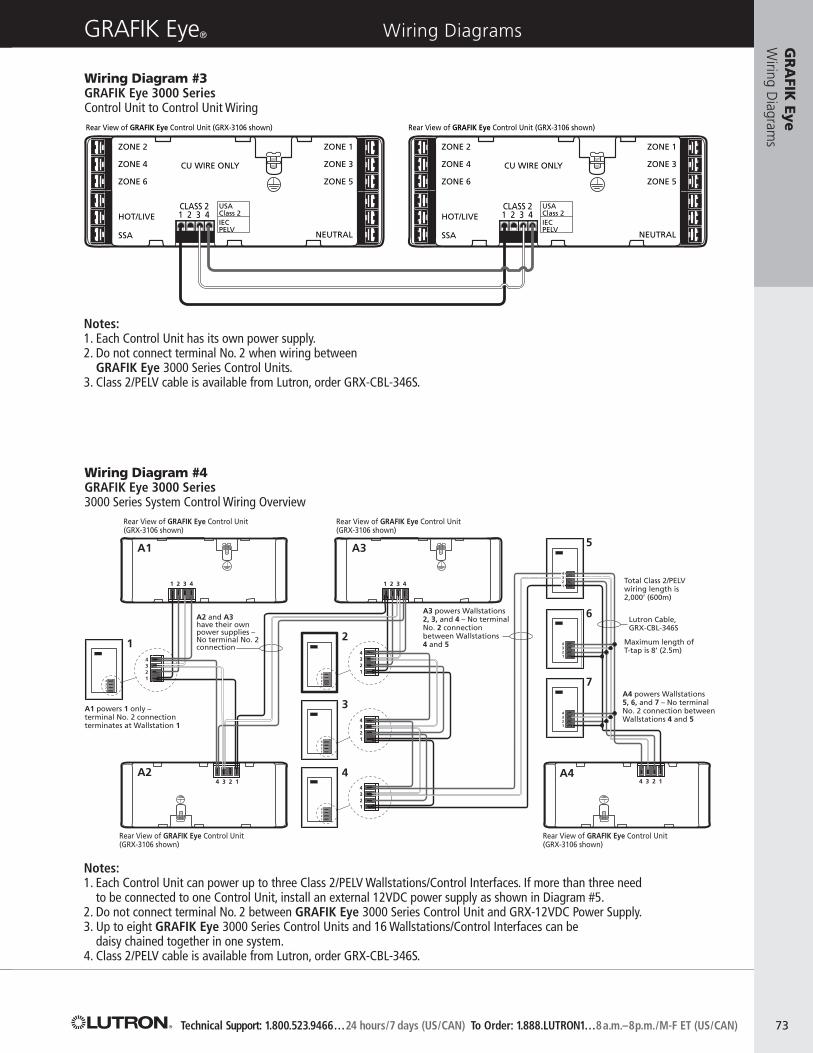
Wiring Diagram #3GRAFIK Eye 3000 SeriesControl Unit to Control Unit Wiring
Notes:1. Each Control Unit has its own power supply.2. Do not connect terminal No. 2 when wiring between
GRAFIK Eye 3000 Series Control Units.3. Class 2/PELV cable is available from Lutron, order GRX-CBL-346S.
A1
12
3
4
5
6
7
A3
A2 A4
A2 and A3 have their own power supplies –No terminal No. 2 connection
Total Class 2/PELVwiring length is2,000’ (600m)
Maximum length ofT-tap is 8’ (2.5m)
A1 powers 1 only – terminal No. 2 connection terminates at Wallstation 1
A4 powers Wallstations5, 6, and 7 – No terminal No. 2 connection between Wallstations 4 and 5
A3 powers Wallstations 2, 3, and 4 – No terminal No. 2 connection between Wallstations4 and 5
Lutron Cable, GRX-CBL-346S
4321
4321
1 2 3 4
4 3 2 1
1 2 3 4
4 3 2 1
4321
4321
4321
4321
4321
4321
4321
4321
4321
Rear View of GRAFIK Eye Control Unit (GRX-3106 shown)
Rear View of GRAFIK Eye Control Unit (GRX-3106 shown)
Rear View of GRAFIK Eye Control Unit (GRX-3106 shown)
Rear View of GRAFIK Eye Control Unit (GRX-3106 shown)
Notes:1. Each Control Unit can power up to three Class 2/PELV Wallstations/Control Interfaces. If more than three need
to be connected to one Control Unit, install an external 12VDC power supply as shown in Diagram #5.2. Do not connect terminal No. 2 between GRAFIK Eye 3000 Series Control Unit and GRX-12VDC Power Supply.3. Up to eight GRAFIK Eye 3000 Series Control Units and 16 Wallstations/Control Interfaces can be
daisy chained together in one system.4. Class 2/PELV cable is available from Lutron, order GRX-CBL-346S.
Wiring Diagram #4GRAFIK Eye 3000 Series3000 Series System Control Wiring Overview
www.lutron.com Lutron World Headquarters: 1.610.282.3800
Rear View of GRAFIK Eye Control Unit (GRX-3106 shown)
Wallstation Wallstation
4321
4321
Lutron cable,GRX-CBL-346S (non-plenum)
4321
4321
Wiring Diagram #5GRAFIK Eye 3000 SeriesWallstation Power Supply (GRX-12VDC) Wiring
Notes:1. Do not connect terminal No. 2 between GRAFIK Eye 3000 Series Control Unit and GRX-12VDC Power Supply.2. Class 2/PELV cable is available from Lutron, order GRX-CBL-346S.
Notes:1. Each terminal can accept up to two #12 AWG (2.5mm2) wires.2. FDBI Hot/Live can be on the same phase or different phase than
the GRAFIK Eye 3000 Series Control Unit Hot/Live.3. Lutron Tu-Wire® ballasts do not require the use of FDBI Power Interface.4. Up to two FDBI interfaces can be wired to a single GRAFIK Eye zone.
Notes:1. Each terminal can accept up to (2) #12 AWG (2.5mm2) wires.2. PB/ELVI Hot/Live can be on the same phase or different phase than the GRAFIK Eye 3000
Series Control Unit Hot/Live.3. Up to two PB/ELVI interfaces can be wired to a single GRAFIK Eye zone.
Technical Support: 1.800.523.9466…24 hours/7 days (US/CAN) To Order: 1.888.LUTRON1…8a.m.–8p.m./M-F ET (US/CAN)
GRAFIK Eye® Wiring DiagramsG
RA
FIK Eye
Wiring D
iagrams
77
Note:Distribution panels can be different phases or voltages (120VAC shown).
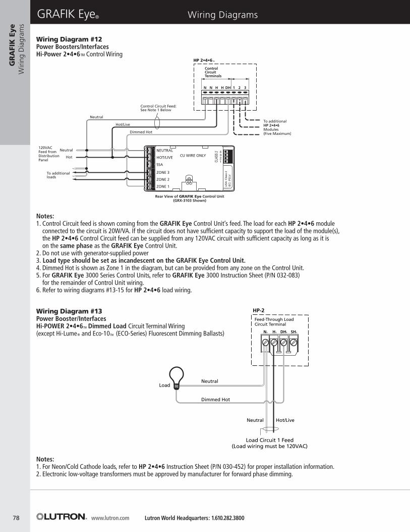
Notes:1. For Neon/Cold Cathode loads, refer to HP 2•4•6 Instruction Sheet (P/N 030-452) for proper installation information.2. Electronic low-voltage transformers must be approved by manufacturer for forward phase dimming.
www.lutron.com Lutron World Headquarters: 1.610.282.3800
GRAFIK Eye® Wiring DiagramsG
RA
FIK
Eye
Wiri
ng D
iagr
ams
78
Wiring Diagram #12Power Boosters/InterfacesHi-Power 2•4•6™ Control Wiring
Notes:1. Control Circuit feed is shown coming from the GRAFIK Eye Control Unit’s feed. The load for each HP 2•4•6 module
connected to the circuit is 20W/VA. If the circuit does not have sufficient capacity to support the load of the module(s),the HP 2•4•6 Control Circuit feed can be supplied from any 120VAC circuit with sufficient capacity as long as it is on the same phase as the GRAFIK Eye Control Unit.
2. Do not use with generator-supplied power3. Load type should be set as incandescent on the GRAFIK Eye Control Unit.4. Dimmed Hot is shown as Zone 1 in the diagram, but can be provided from any zone on the Control Unit.5. For GRAFIK Eye 3000 Series Control Units, refer to GRAFIK Eye 3000 Instruction Sheet (P/N 032-083)
for the remainder of Control Unit wiring.6. Refer to wiring diagrams #13-15 for HP 2•4•6 load wiring.
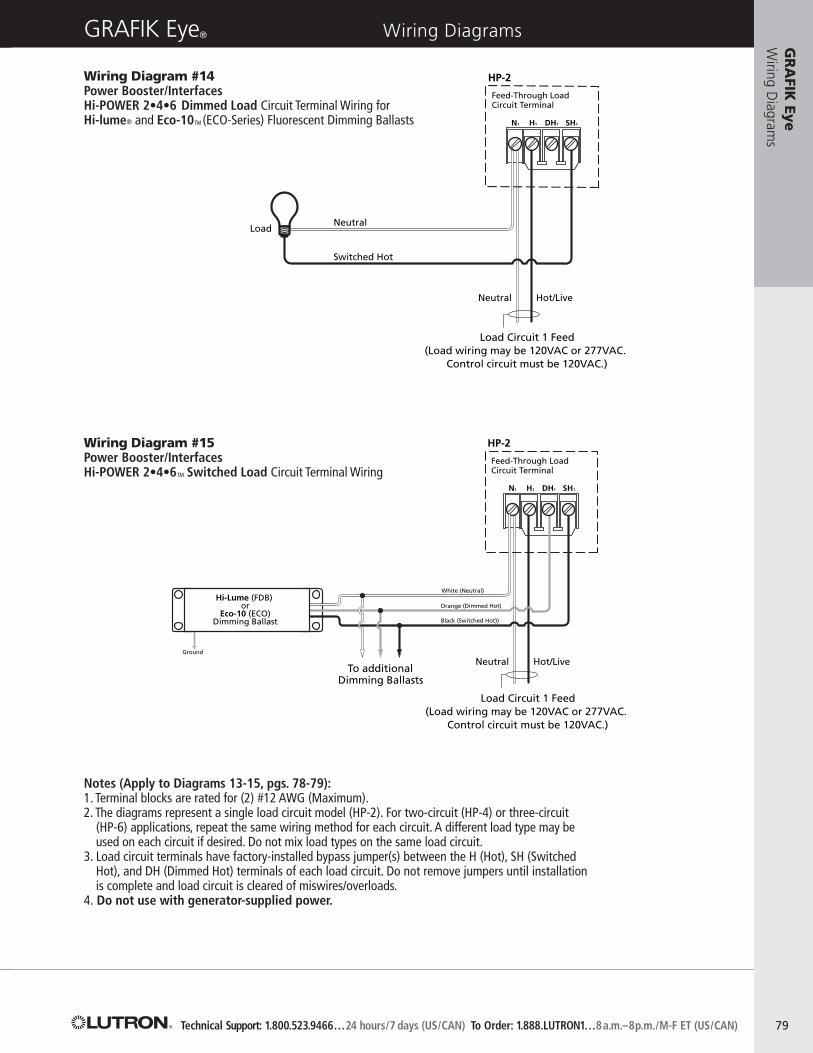
Load Circuit 1 Feed(Load wiring may be 120VAC or 277VAC.
Control circuit must be 120VAC.)
Neutral
Neutral Hot/Live
Switched Hot
Load
N1 H1 DH1 SH1
ring Diagram 10OWER 2•4•6 Dimming Module System
d Circuit Terminal Wiring for Switched Loads:ndescent, Magnetic Low-Voltage, tronic Low-Voltage, Neon/Cold Cathode,-Capacitive Fluorescent and Metal Halide
Wiring Diagram #11HI-POWER 2•4•6TM Dimming Module SystemLoad circuit terminal wiring for dimmed loads:Hi-lume® and Eco-10® (ECO-Series)Fluorescent Dimming Ballasts
HP-2
Feed-Through Load Circuit Terminal
Load Circuit 1 Feed(Load wiring may be 120VAC or 277VAC.
Control circuit must be 120VAC.)
Notes (Apply to Diagrams 13-15, pgs. 78-79):1. Terminal blocks are rated for (2) #12 AWG (Maximum).2. The diagrams represent a single load circuit model (HP-2). For two-circuit (HP-4) or three-circuit
(HP-6) applications, repeat the same wiring method for each circuit. A different load type may beused on each circuit if desired. Do not mix load types on the same load circuit.
3. Load circuit terminals have factory-installed bypass jumper(s) between the H (Hot), SH (SwitchedHot), and DH (Dimmed Hot) terminals of each load circuit. Do not remove jumpers until installation is complete and load circuit is cleared of miswires/overloads.
Notes:1. Use (2) #12 AWG (2.5mm2) wires for terminals
1 and 2, and (1) #18 AWG (1.0mm2) twisted shieldedpair for terminals 3 and 4.
2. Drain/Shield must be connected as shown, and terminated only at Power Panel if Drain Terminal is provided. It is easiest to connect the bare drainwires and cut off the outside shield throughout thecontrol link.
3. Up to eight GRAFIK Eye 4000 Series Control Units(addresses) and 16 Wallstations/Control Interfacescan be daisy chained together in one system.A 16-zone Control Unit requires two addresses;a 24-zone Control Unit requires three addresses.
4. Class 2/PELV cable is available from Lutron,order GRX-CBL-46L.
Notes:1. Use (2) #12 AWG (2.5mm2) wires for terminals
1 and 2, and (1) #18 AWG (1.0mm2) twisted shielded pair for terminals 3 and 4.
2. All control wiring is Class 2/PELV. Do not place any of these wires in with line-voltage (mainsvoltage) wiring.
3. (2) #12 AWG (2.5mm2) wires will not fit in theWallstations/Control Interfaces terminal blocks.Use the diagram shown here to make the connections in the wallbox. #12 AWG (2.5mm2)wiring is necessary to minimize voltage drop.
4. Drain/Shield must be connected as shown. Do notconnect to Ground (Earth) or Wallstations/ControlInterfaces. It is easiest to connect the bare drainwires and cut off the outside shield throughoutthe control link.
5. Make wire connections inside the wallbox andPower Panel or in a junction box (provided by others) within 8’ (2.4m) of the terminals.
6. Class 2/PELV cable is available from Lutron,order GRX-CBL-46L.
GR
AFI
K E
yeW
iring
Dia
gram
s
80
Technical Support: 1.800.523.9466…24 hours/7 days (US/CAN) To Order: 1.888.LUTRON1…8a.m.–8p.m./M-F ET (US/CAN)
www.lutron.com Lutron World Headquarters: 1.610.282.3800
GRAFIK Eye® Wiring DiagramsG
RA
FIK
Eye
Wiri
ng D
iagr
ams
82
1 2 3 4
RS-232 Link
GRX-RS232/GRX-PRG
1 2 3 4 5
COM
50' (15m)(Maximum)
RxDPC or A/VEquipment
TxD
MUX Link
Circuit Selector
Power Panel
Wiring Detail
Drain
Drain
Sen
se
+24
V
Com
mon
Com
mon
Dra
in
Dra
in
MU
X
MU
X
MU
X
MU
X
Link Link
Data B OKPowerData A OK
A B
1 2 3 4 D 5 C D
Rear View of GRAFIK Eye Control Unit (GRXSLD-4103 is shown)
1 2 3 4 D 5 C D
1 2 3 4 D 5
SSA
SSA RTN
DO NOT USE
2 IN, OUT
1 IN, OUT
DO NOT USE
MUX (4) INMUX (3) INMUX (4) OUTMUX (3) OUT
USA
: CLA
SS 2
IEC
: PEL
V
CU WIRE ONLY
Class 2/PELVControl Wiring1: Common2: 24VFW
Data Link3: MUX4: MUX
To additional Wallstations/ControlInterfaces (16 maximum)
Wiring Diagram #19GRAFIK Eye 4000 SeriesRS-232 Interface (GRX-RS232) or Astronomical Timeclock and Programmer Interface (GRX-PRG) Wiring
Notes:1. Use (2) #12 AWG (2.5mm2) wires for terminals 1 and 2,
and (1) #18 AWG (2.5mm2) twisted shielded pair for terminals 3 and 4.2. Drain/Shield must be connected as shown, and terminated only
at Power Panel if Drain terminal is provided. It is easiest to connect the bare drain wires and cut off the outside shield throughout the control link.
3. Up to eight GRAFIK Eye 4000 Series Control Units and 16 Wallstations/ Control Interfaces can be daisy chained together in one system.
4. Class 2/PELV cable is available from Lutron, order GRX-CBL-46L.
Technical Support: 1.800.523.9466…24 hours/7 days (US/CAN) To Order: 1.888.LUTRON1…8a.m.–8p.m./M-F ET (US/CAN)
Notes:1. Use (2) #12 AWG (2.5mm2) wires for terminals 1 and 2, and (1) #18 AWG (1.0mm2) twisted shielded pair
for terminals 3 and 4.2.An additional #18 AWG (1.0mm2) wire can be used as a “sense” line from terminal
5 of another panel. This sense line allows an Emergency (Essential) Lighting Panel to “sense” when Normal (Non-Essential) power is lost. For more information on Emergency,see Application Notes pg. 176.
3. For Panel to Panel wiring, refer to Power Panel Instruction Sheet.4. Centralized Lighting Control Systems have separate Power Panel and Control links. GRAFIK Eye
4000 Series Power Panels connect to the same link as Control Units and Wallstations/ Control Interfaces.5. Class 2/PELV cable is available from Lutron, order GRX-CBL-46L.6. DMX512 Class 2/PELV cable is available from Lutron, order GRX-CBL-DMX
(available in 250’ and 500’ lengths).
GRAFIK Eye® Wiring Diagrams
LUTRON
SELECT CIRCUIT
Data A OK Power Data B OK
1 2 3 4 D 5 C D
1 2 3 4 D 5 C D
Co
mm
on
Co
mm
on
+24
VFW
Sen
se
MU
X
MU
X
Dra
in
Dra
in
MU
X
MU
X
Circuit
1
2
Link
ALink
B
NovaTB®-StyleDMX Jack
To GRAFIK Eye 4000 Series Control Unitor Centralized Lighting Control System Panel
Power Panel Circuit Selector
Power Panel
Link AClass 2/PELVControl Wiring1: Common2: 24VFW
Link AClass 2/PELVData Link3: MUX4: MUX
Link BClass 2/PELVData Link4: No Connection5: No Connection
Link BClass 2/PELVData Link1: Common2: –3: +
To additionalpower panels
Wires must be daisy-chained and capped off at both ends
123
4
5
45123
DMX Theatrical Console
LUTRON
Link A Link B
GR
AFIK
EyeW
iring Diagram
s
83
4
3
2
1
54368
MUXCOM
COM
MUXACAC
MUX
MUX
+V
EDU TERMINAL BLOCKEDU TERMINAL BLOCK
MU
X
MU
X
GN
D
AC
2
AC
1
CO
M
+12
MU
X
MU
X
GN
D
AC
2
AC
1
CO
M
+12
ACAC
GRDAC
ACGRD
To GRAFIK Eye3000/4000
Control Unit(see wiring
diagram #6 or #18
Sivoia QED Controller
24VAC Transformer
24VAC Transformer
Connect pins 3, 4 and 5 only for eachadditional Electronic Drive Unit
Lutron Cable, SVQ-CBL-250SG-SVC pins 1 through 7 connectedto first Electronic Drive Unit
Sivoia QED Electronic Drive Unit Sivoia QED Electronic Drive UnitWiring Diagram #21GRAFIK Eye 3000/4000 SeriesSivoia QED™ Controller (SG-SVCN) Wiring
www.lutron.com Lutron World Headquarters: 1.610.282.3800
GRAFIK Eye® Wiring DiagramsG
RA
FIK
Eye
W
iring
Dia
gram
s
84
Notes:1. Sivoia QED Electronic Drive Units shown will be controlled together as one zone.2. One SG-SVC is needed per group of Sivoia QED Controllable Window Treatments
(up to 64 EDUs) moving together.
12
34
5
ON
COM1
CLOSE1
STOP1
OPEN1OPEN
1CL
OSE1
OPEN
2CL
OSE2
OPEN
3CL
OSE3
OPEN
4CL
OSE4
OPEN
ALL
CLOS
E AL
L
MAS
TER
CONT
ROL
S
PROG
RAM
STAT
US
POW
ER
OPTI
ONS
MS
240V
120V
NN
C1O1
NC
2O
2N
C3O3
NC
4O
4
COM2
CLOSE2
STOP2
OPEN2
COM3
CLOSE3
STOP3
OPEN3
COM4
CLOSE4
STOP4
OPEN4
COM
CLOSE
STOP
OPEN
Power Feed Wiring
Motor 1
*Motor earth/ground wire not shown.
Motor 2
Motor 3
Motor 4
GRX-4M-GC AC Group Controller
AC Motor 1 AC Motor 2 AC Motor 3 AC Motor 4
Wiring entry knockouts
Distribution Panel
Technical Support: 1.800.523.9466…24 hours/7 days (US/CAN) To Order: 1.888.LUTRON1…8a.m.–8p.m./M-F ET (US/CAN)
GRAFIK Eye® Wiring DiagramsG
RA
FIK Eye
Wiring D
iagrams
85
Wiring Diagram #22GRAFIK Eye 3000/4000 SeriesFour-Motor AC Group Controller (GRX-4M-GC) Wiring
12
34
5
ON
PROGRAMSTATUS POWER
OPTIONS
Neutral
120V
240V
MotorSupply
MUX
MUX
V+
CO M
12
34
5
ON
ADDRESS
ON 4
3
2
1
OPEN ALL
CLOSE ALL
OPEN 4
CLOSE 4
OPEN 3
CLOSE 3
OPEN 2
CLOSE 2
OPEN 1
CLOSE 1
SW Live1B
SW Live1A
Neutral
SW Live2B
SW Live2A
Neutral
SW Live3B
SW Live3A
Neutral
SW Live4B
SW Live4A
Neutral
Zone 4
Zone 6
Hot/Live
SSA
CU WIRE ONLY
Zone 2
1 2 3 4
Zone 3
Zone 5
Neutral
Zone 1
USACLASS 2IECPELV
ComOpen AllStop AllClose All
Class 2/PELV Wiring
Group Controller
Coopersburg, PA 18036 USAwww.lutron.com
500-9574 Rev. A
GRX-4M-GC4 MOTOR GROUP CONTROLLER110-127 V~ 60 Hz20 A Max. Input Current
LOAD TYPESSingle Phase, Bi-directional Motor5 A, 1/4 HP per Channel at 120 V~
TYPES DE CHARGESPhase Simple, Moteur Bidirectionel5 A, 1/4 HP par Canal a 120 V~