Page 1
GRANT AGREEMENT NO.: 732174
Call: H2020-ICT-2016-2017
Topic: ICT-13-2016
Type of action: RIA
Orchestration and Reconfiguration Control Architecture
D2.4: Development and Integration
of Showcases in Year 2 Revision: v.1.0
Work package WP2
Task Task 2.3
Due date 31/12/2018
Submission date 21/12/2018
Deliverable lead TUD
Version 1.0
Authors Wei Liu (IMEC) , Ingrid Moerman (IMEC), Xianjun Jiao (IMEC),
Roberto Bomfin (TUD), Joao F. Santos (TCD), Walter Nitzold (NI),
Seyed Ali Hassani (KUL), Muhammad Aslam (IMEC), Martin
Danneberg (TUD), Jonathan van de Belt (TCD)
Page 2
D2.4: Development and Integration of Showcases in Year 2
© ORCA Consortium 2017-2020 Page 2 of 22
Reviewers Wei Liu (IMEC), Joao F. Santos (TCD)
Abstract This document specifies the showcases to be demonstrated after the
development of year 2. The showcases were defined in D2.1 with the
purpose of being examples of how people can use ORCA facilities,
and the functionalities were described in D2.2 such that the
experimenters can have a clear understanding of what ORCA can
offer.
Keywords
Disclaimer
The information, documentation and figures available in this deliverable, are written by the ORCA
(Orchestration and Reconfiguration Control Architecture) – project consortium under EC grant
agreement 732174 and does not necessarily reflect the views of the European Commission. The
European Commission is not liable for any use that may be made of the information contained herein.
Confidential - The information contained in this document and any attachments are confidential. It is
governed according to the terms of the project consortium agreement
Copyright notice
© 2017 - 2020 ORCA Consortium
Acknowledgment
This report has received funding from the EC under the grant agreement 731274.
* R: Document, report (excluding the periodic and final reports)
Project co-funded by the European Commission in the H2020 Programme
Nature of the deliverable: R
Dissemination Level
PU Public, fully open, e.g. web ✓
CI Classified, information as referred to in Commission Decision 2001/844/EC
CO Confidential to ORCA project and Commission Services
Page 3
D2.4: Development and Integration of Showcases in Year 2
© ORCA Consortium 2017-2020 Page 3 of 22
EXECUTIVE SUMMARY
The ORCA project intends to offer end-to-end (E2E) experimentation facilities to the research
community making use of novel Software-defined Radio (SDR) and Software-defined Networking
(SDN) evolutions. Thus, this deliverable provides examples on how the ORCA showcases and
functionalities can be utilized by external partners. Comparing to Y1, the showcases in Y2 are further
extended to demonstrate the functionalities that have been improved. In particular, Showcase 1
demonstrates a high throughput mmWave system that can be configured in real-time in order to optimize
the use of resources. In this year’s showcase, mmWave link is demonstrated as backbone link in
showcase4. Showcase 2 targets at demonstrating spectrum sharing capability of ORCA SDRs applied
to remotely controlled robots while maintaining low latency link performance. Showcase 3 demonstrates
the coordination between SDN and SDRs, as well as the different types of radio slicing and virtualization
applied to different contexts. And finally, Showcase 4 aims to combine LTE and WiFi as well as 5G
type of links into a unified experimental platform for RAT interworking studies with E2E capabilities.
Page 4
D2.4: Development and Integration of Showcases in Year 2
© ORCA Consortium 2017-2020 Page 4 of 22
TABLE OF CONTENTS
EXECUTIVE SUMMARY ....................................................................................................................3
TABLE OF CONTENTS .......................................................................................................................4
LIST OF FIGURES ...............................................................................................................................6
ABBREVIATIONS ................................................................................................................................7
1 INTRODUCTION ..................................................................................................................8
2 SHOWCASE 1: HIGH THROUGHPUT .............................................................................9
2.1 Motivation .................................................................................................................................9
2.2 Demonstrator ............................................................................................................................9
2.3 Integration to Showcase 4 – mmWave backhaul ....................................................................10
2.4 Mapping to the ORCA KPIs ...................................................................................................10
2.5 Innovation Aspects .................................................................................................................11
Main contributions & achievements ......................................................................................................11
Beyond the state-of-the-art .....................................................................................................................11
2.6 Involved partners and their role ..............................................................................................11
2.7 Conclusion ..............................................................................................................................11
3 SHOWCASE 2: LOW LATENCY INDUSTRIAL COMMUNICATION ......................12
3.1 Motivation ...............................................................................................................................12
3.1 Demonstrator ..........................................................................................................................12
3.2 Mapping to the ORCA KPIs ...................................................................................................13
3.3 Innovation Aspects .................................................................................................................13
Main contributions & achievements ......................................................................................................13
Beyond the state-of-the-art .....................................................................................................................14
3.4 Involved partners and their role ..............................................................................................14
3.5 Conclusion ..............................................................................................................................14
4 SHOWCASE 3: LOW LATENCY AND HIGH THROUGHPUT INDUSTRIAL
COMMUNICATION ...........................................................................................................................15
4.1 Motivation ...............................................................................................................................15
4.2 Demonstrator ..........................................................................................................................15
4.3 Mapping to the ORCA KPIs ...................................................................................................16
4.4 Innovation Aspects .................................................................................................................16
Main contributions & achievements ......................................................................................................16
Beyond the state-of-the-art .....................................................................................................................16
Page 5
D2.4: Development and Integration of Showcases in Year 2
© ORCA Consortium 2017-2020 Page 5 of 22
4.5 Involved partners and their role ..............................................................................................17
4.6 Conclusion ..............................................................................................................................17
5 SHOWCASE 4: INTERWORKING AND AGGREGATION OF MULTIPLE RADIO
ACCESS TECHNOLOGIES ..............................................................................................................18
5.1 Motivation ...............................................................................................................................18
5.2 Demonstrator ..........................................................................................................................18
5.3 Mapping to the ORCA KPIs ...................................................................................................19
5.4 Innovation Aspects .................................................................................................................19
Main contributions & achievements ......................................................................................................19
Beyond the state-of-the-art .....................................................................................................................19
5.5 Involved partner and their role ................................................................................................20
5.6 Conclusion ..............................................................................................................................20
6 CONCLUSIONS ...................................................................................................................21
REFERENCES .....................................................................................................................................22
Page 6
D2.4: Development and Integration of Showcases in Year 2
© ORCA Consortium 2017-2020 Page 6 of 22
LIST OF FIGURES
Figure 1 Testbed in a moveable trolley. .............................................................................................10
Figure 2 ORCA SC2 heterogeneous network for cloud-based remote robot controlling and
efficient spectrum utilization ...............................................................................................................12
Figure 3 Demonstrator using FRANKA EMIKA robot arms connected to the USRP-SDR
platform. ................................................................................................................................................13
Figure 4 Showcase 3 demonstrator overview.....................................................................................16
Figure 5 Showcase 4 demonstration scenario from Year 2. .............................................................18
Page 7
D2.4: Development and Integration of Showcases in Year 2
© ORCA Consortium 2017-2020 Page 7 of 22
ABBREVIATIONS
AP Access Point
CPU Central Processing Unit
CR Cognitive Radio
CLAWS Cross-Layer Adaptable Wireless System
DSS Dynamic Spectrum Sharing
E2E End-to-end
FPGA Field-Programmable Gate Array
GFDM Generalized Frequency Division Multiplexing
IBFD In-Band Full Duplex
IQ In-phase and Quadrature
LWA LTE-WLAN Aggregation
LWIP LTE-WLAN radio level integration with IP security tunnel
MAC Media Access Control
MCS Modulation Coding Scheme
mmWave Millimeter Wave
NFV Network Function Virtualisation
OCM On-Chip Memory
ORCA Orchestration and Reconfiguration Control Architecture
QoS Quality of Service
PHY Physical Layer
RAT Radio Access Technology
RF Radio Frequency
SDN Software-Defined Networking
SDR Software-Defined Radio
TDD Time Division Duplex
UD User Device
USRP Universal Software Radio Peripherals
V-TX Virtualized Transmitter
VR Virtual Reality
Page 8
D2.4: Development and Integration of Showcases in Year 2
© ORCA Consortium 2017-2020 Page 8 of 22
1 INTRODUCTION
Future wireless communication systems will need to consider new aspects that were not so important
before. For instance, simultaneous applications that possess diverging Quality of Service (QoS)
requirements and high data rates will use the same wireless infrastructure, which is certainly challenging
for the upcoming technologies, since the systems will have to support more than one wireless
technology. In addition, the amount and variety of devices connected to the network will increase
substantially, which also brings new challenges. Moreover, the lack of available spectrum gives rise to
Dynamical Spectrum Sharing (DSS) and Cognitive Radio (CR) networking. In order to deal this new
and more complex communication scenario, Software-defined Radio (SDR) devices will be utilized to
achieve the requirements previously described. With the capability of providing a flexible physical layer
(PHY) transceivers by adapting its parameters at real-time, SDRs are suitable for future applications
because they can adapt according to the network needs, resulting in a more efficient system where the
resources are used more wisely. In conjunction with SDRs, Software Defined Networking (SDN) will
allow the virtualization of PHY instances, creating logical networks that are capable of providing
services to diverse categories according to QoS requirements.
In this context, ORCA intends to merge SDR, DSS and SDN into a framework in order to allow end-to-
end (E2E) networking experiments to the research community and industry, including real-time SDR
platforms with low-runtime latencies, high throughput and flexibility. These experiments are meaningful
to several market segments such as manufacturing, automotive industry, health care, etc.
In order specify what the ORCA facilities can provide, four showcases were defined in deliverable 2.1
(D2.1) [1]. The showcases target at being a basis for the possible experimenters. Additionally, in
deliverable 2.2 (D2.2) [2], it was defined the ORCA functionalities organized as SDR Data Plane, Basic
SDR Control Plane and Advanced SDR Control and Management. Similarly to the showcase definition
for year 1 exposed in deliverable 2.3 (D2.3) [3], this deliverable aims at demonstrating functionalities
that were available for year 2. The summary of showcases are specified below:
Showcase 1 – The high throughput Millimeter Wave (mmWave) demonstrator will show the real-time
re-configuration capability of the E2E link at 60GHz.
Showcase 2 – The low latency systems are used for industrial applications and will demonstrate different
platforms remotely controlling robots in the same spectrum.
Showcase 3 – The low latency and high throughput demonstrator will show the different approaches to
radio slicing, as well as the coordination between SDN and SDR to establish E2E services.
Showcase 4 – The Multi-Radio Access Technology (RAT) interworking platform will show various
options to run E2E applications over multiple possible interworking radio access technologies such as
LTE and WiFi.
Page 9
D2.4: Development and Integration of Showcases in Year 2
© ORCA Consortium 2017-2020 Page 9 of 22
2 SHOWCASE 1: HIGH THROUGHPUT
2.1 Motivation
The novel spectrum bands brought by the mmWave technologies will play an important role in the future
communication systems. For instance, the data rate per user is expected to increase in the order of 10
Gbit/s. Due to limited bandwidth of conventional systems, the mmWave schemes become a very
promising solution for these applications, since the bandwidth is largely increased in a way that users
can experience higher data rates in cellular systems [4]. In addition, mmWave systems allow much more
spectrum reuse than conventional systems, since the mmWave cells are much smaller and the
transmitted signals are irradiated through narrower beams, decreasing interference substantially.
Consequently, mmWave transmissions allow not only high throughput transmission due to large
bandwidth spans, but it also supports larger number of users due to frequency reuse. Another feasible
application is fronthaul or backhaul, in cases where wired connection are more expensive or not possible
at all [5].
Another important aspect of future communication systems is the real-time reconfiguration capability.
This is a key feature in order to allow efficient exploitation of the resources. Thus, this showcase intends
to demonstrate the reconfiguration capability of the TUD mmWave communication system at 57-66
GHz. In particular, this real-time system can configure a beam-steering algorithm according to the
channel behaviour, where the channel can be variant or static, depending on whether the user device is
moving or not.
2.2 Demonstrator
This showcase targets at demonstrating the real-time re-configurability feature of the 60 GHz mmWave
wave system (see [6] and [10] for details). The reconfigurable parameters include Modulation Coding
Scheme (MCS), beam steering algorithm and mobility. Depending on the scenario, e.g., with or without
mobility, MCS and the beam steering algorithm can be properly configured in order to maximize
transmission rate with reasonable performance. Using an antenna rotation table, a mobility scenario can
be simulated in a pre-defined way. The testbed is equipped with two moveable trolley structures depicted
in the next figure. They are composed by the following components:
o Sibeam V band transceiver and antenna array: these components is capable of
transmitting and receiving signals over-the-air in the V band, i.e., 57-66 GHz using the
beam alignment feature.
o Power Supply for Sibeam: this component is simply the power supplier of the V band
transceiver board.
o PXI baseband chassis: NI modular system based on PXI components to provide
baseband processing and beamsteering MAC functionality
Page 10
D2.4: Development and Integration of Showcases in Year 2
© ORCA Consortium 2017-2020 Page 10 of 22
Figure 1 Testbed in a moveable trolley.
The demonstrator consists of two devices as the one depicted in Figure 1, which are the access point
(AP) and user device (UD). The UD differs from AP with the rotation table where the antenna is
mounted. The rotation table allows us to emulate mobility and study the system under more dynamical
conditions.
2.3 Integration to Showcase 4 – mmWave backhaul
In year 2, we have integrated the mmWave demonstrator of Showcase 1 with the multi-RAT base station
defined in Showcase 4, where the mmWave link will serve as the backhaul for the base station, as
illustrated in Figure 5 in Section 5. Our motivation to perform such integration has two main aspects.
First, the mmWave link as a backhaul solution will be common in future networks, in cases where fiber
is not feasible to each cell, e.g., in cases of small base stations. Secondly, with this integration we
demonstrate that this systems can be integrated to each other, increasing the range of possible
experiments with the ORCA facilities. To avoid duplications, more details of this integration and how
mmWave backhaul link is being used are available in Section 5.
2.4 Mapping to the ORCA KPIs
This showcase will contribute to the KPI’s 4 and 5. KPI 4 is related to use of real-time steerable antennas,
and KPI 5 is related bi-directional Time Division Duplex (TDD) protocol enabling beam tracking. This
showcase is in accordance with KPI 4 since we demonstrate a functioning real-time system exploiting
the steerable mmWave antennas. Additionally, it is also related to KPI 5 since the beam tracking
algorithm uses the bi-direction TDD protocol. This showcase demonstrates the capabilities to support
the ORCA partners for performing research towards future communication networks.
Page 11
D2.4: Development and Integration of Showcases in Year 2
© ORCA Consortium 2017-2020 Page 11 of 22
2.5 Innovation Aspects
Main contributions & achievements
This showcase demonstrates a re-configurable real-time mmWave system with flexible beam steering
algorithm and MCS. This setup is very relevant for research, since there is no cellular protocol with
beam steering defined yet. With our mmWave equipment, this showcase intends to demonstrate the
flexible real-time setup working under realistic environment. In addition, the mobility environment
emulated by the rotation table can be further used for future research and experiments. Thus, the ORCA
project achieves the goal of enabling mmWave related experiments to the research community and
industry with our flexible mmWave system.
Additionally, this showcase is integrated with showcase 4, which can serve as an example for future
experiments in TUD’s testbed.
Beyond the state-of-the-art
This showcase investigates the benefits of having a real-time re-configurable mmWave link under
mobility scenario. The outcomes are relevant for high throughput cellular systems. Since there is still
no open real time cellular protocol available, this showcase can be a basis for future development of this
technology.
2.6 Involved partners and their role
TUD provides and hosts the mmWave baseband including beam steering functionality with support of
NI. NI will guide TUD to implement required changes to its platform to ease testbed management and
configurability. This includes also the provision of additional configuration parameters if needed to
control and monitor the NI platform. Furthermore, NI will provide guidance for planning of testbed
experiments.
TUD is responsible for integrate the functionalities to the testbed and make it be accessible for external
experimenters.
2.7 Conclusion
It is clear that the new spectral bands made possible by the mmWave transmission will play an important
role for future communication systems. In particular, new applications such as Virtual Reality (VR) will
demand high data rate transmission and cellular cells will be more dense. In this context, the real-time
mmWave system of ORCA enables researchers to investigate the relevant aspects of PHY and MAC of
these systems through TUD’s testbed. Thus, this showcase was built in order to provide a flexible
mmWave PHY structure with capabilities of real time reconfiguration, beam alignment and beam
tracking, such that ORCA can contribute to the high throughput mmWave researches of the future
communication systems, since the evaluation of new applications in a realistic platform will be made
possible.
Page 12
D2.4: Development and Integration of Showcases in Year 2
© ORCA Consortium 2017-2020 Page 12 of 22
3 SHOWCASE 2: LOW LATENCY INDUSTRIAL COMMUNICATION
3.1 Motivation
Wireless communication systems for industrial applications is a major topic for the development of
upcoming technologies, since it is not always possible or feasible to install complex cabled
communication systems in a factory hall. Thus, with flexibility and potential of wireless systems, new
applications that can improve the production processes are possible. For instance, remotely controlled
robots will be deployed with more flexibility and less costs. In this cases, the wireless connection has to
deal with low-latency, reliability and optimization of radio resources, since in general there are several
applications that require the spectrum. In this context, this showcase aims at demonstrating the capability
of ORCA’s SDRs of sharing the same spectrum under the low-latency constraint, where three different
systems work simultaneously to remotely control multiple robots, a scenario which is expected in an
industrial factory. We also demonstrate how different PHY-MAC architectures developed by ORCA
partners can communicate with each other, and with standard compliant off-the-shelf devices.
3.1 Demonstrator
Figure 2 shows the overview of the SC2 demonstration where five communication devices share the
spectrum. The two KU Leuven SDRs benefit from an advanced cross-layer architecture which enables
flexible run-time reprogramming of the MAC layer. These two SDRs are interfaced with two reverse
pendulum robots. These brainless robots rely on the IMEC SDR, which plays the role of a central
processing unit and generates appropriate commands for the robots to maintain balance. The IMEC SDR
makes use of the TAISC framework running on an ARM processor for MAC layer, and IP cores in
FPGA for PHY layer, making it both flexible and low-latency. This network has to provide low-latency
communication between the clients, i.e. the balancing robots, and the processing unit in such a manner
that minimizes the interval between reading the sensory data and applying moving commands. Still this
network shares the spectrum opportunistically between the robots and the processing unit, while the
GFDM has to provide a very robust low latency link providing sufficient data rate for the robotic arms.
Figure 2 ORCA SC2 heterogeneous network for cloud-based remote robot controlling and efficient spectrum
utilization
Additionally, the two KUL In-Band Full Duplex (IBFD) SDRs present a low-latency full duplex
network in which concurrent send and receive is possible at the same channel. We demonstrate how
Page 13
D2.4: Development and Integration of Showcases in Year 2
© ORCA Consortium 2017-2020 Page 13 of 22
IBFD technology helps to improve latency and throughput in a real-life scenario. Employing flexibility,
reconfiguration and re-programmability, this demo also shows a run-time half and full duplex mode
selection.
Furthermore, IMEC demonstrates a five-node network, which comprises one SDR running 4 virtualized
transmitters (V-TX), and four receivers running on 4 different devices. The V-TX is able to transmit the
data at the same time on different channels. The four receivers operating at different frequency are
capable to decode the data sent by V-TX, showing that the virtualized transmitters on SDR are operating
correctly.
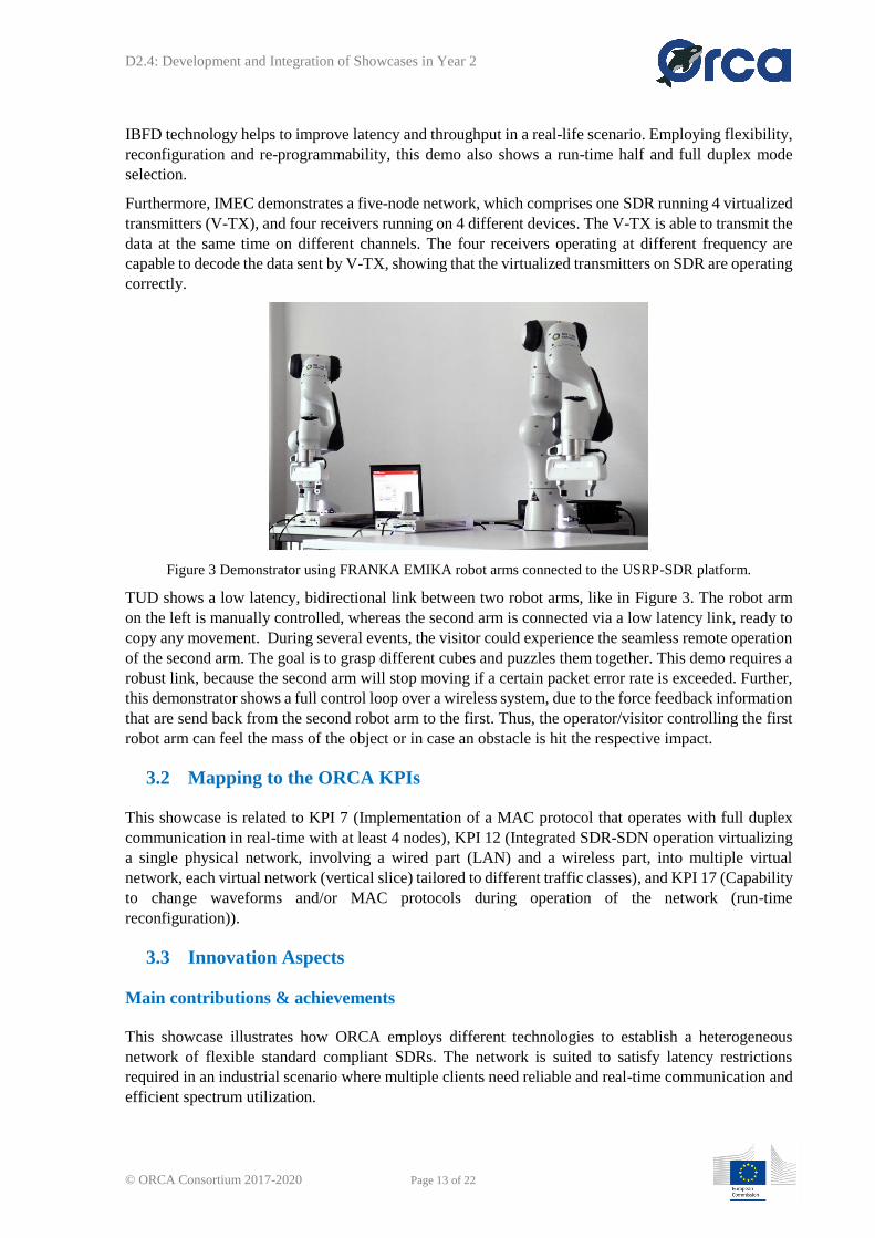
Figure 3 Demonstrator using FRANKA EMIKA robot arms connected to the USRP-SDR platform.
TUD shows a low latency, bidirectional link between two robot arms, like in Figure 3. The robot arm
on the left is manually controlled, whereas the second arm is connected via a low latency link, ready to
copy any movement. During several events, the visitor could experience the seamless remote operation
of the second arm. The goal is to grasp different cubes and puzzles them together. This demo requires a
robust link, because the second arm will stop moving if a certain packet error rate is exceeded. Further,
this demonstrator shows a full control loop over a wireless system, due to the force feedback information
that are send back from the second robot arm to the first. Thus, the operator/visitor controlling the first
robot arm can feel the mass of the object or in case an obstacle is hit the respective impact.
3.2 Mapping to the ORCA KPIs
This showcase is related to KPI 7 (Implementation of a MAC protocol that operates with full duplex
communication in real-time with at least 4 nodes), KPI 12 (Integrated SDR-SDN operation virtualizing
a single physical network, involving a wired part (LAN) and a wireless part, into multiple virtual
network, each virtual network (vertical slice) tailored to different traffic classes), and KPI 17 (Capability
to change waveforms and/or MAC protocols during operation of the network (run-time
reconfiguration)).
3.3 Innovation Aspects
Main contributions & achievements
This showcase illustrates how ORCA employs different technologies to establish a heterogeneous
network of flexible standard compliant SDRs. The network is suited to satisfy latency restrictions
required in an industrial scenario where multiple clients need reliable and real-time communication and
efficient spectrum utilization.
Page 14
D2.4: Development and Integration of Showcases in Year 2
© ORCA Consortium 2017-2020 Page 14 of 22
Beyond the state-of-the-art
While most of the available off-the-shelf communication devices suffer from a rigid PHY realization or
slow MAC implementation, the enhanced cross-layer adaptable wireless system (CLAWS) PHY-MAC
architecture in the KUL SDR enables an application-dependent trade-off between flexibility and low-
latency. Users can use a MAC protocol implemented in a MicroBlaze softcore, or alternatively rely on
the fast bare metal dedicated MAC implementation that is tightly coupled with the PHY to achieve
minimal latency. In addition, this implementation has a lot of features to interrupt the MAC from the
PHY, e.g., for the transmitter based collision detection.
The IMEC SDR provides a flexible and low latency state-of-the-art solution, which in terms of latency,
outperforms the off-the-shelf commercial chipsets. This is achieved by unifying the flexible MAC layer
implemented in TAISC, a cross-platform MAC protocol compiler and execution engine and capable of
modifying the MAC protocol even after deployment, running on ARM processor and low-latency PHY
layer implemented in FPGA. Reducing turnaround time in PHY layer, employing On-Chip Memory
(OCM) in ARM processor and low latency communication link between FPGA and ARM processor are
the major sources of achieving low latency.
The GFDM transceiver shows a 300 µs link between two robotic arms enabling a control loop
application running over a wireless network. Further, this demo needs to ensure that a specific packet
error rate (less than 20 wrong packets) is not exceeded while maintaining a static packet rate of 10
packets per millisecond.
3.4 Involved partners and their role
TUD will apply the GFDM PHY to control a robot arm from distance by moving another robot arm in
a different location. GFDM is able to avoid signals generated by KUL and IMEC radios, and make use
of the remaining spectrum very efficiently.
KUL and IMEC will demonstrate a 3-node mesh network, comprising two different types of standard
compliant SDRs. The network provides low-latency and reliable communication between two robots
and a central processing unit.
KUL will also present a 2-node network, including IBFD devices and shows how full duplex technology
improves the latency requirements in a real-life scenario, whereas IMEC demonstrates 4 virtualized
Zigbee transmitters successfully operating on a single SDR.
3.5 Conclusion
This showcase demonstrates how different ORCA systems can work simultaneously by sharing the same
spectrum, in which we utilize this functionality for an industrial application. Each of the systems is able
to maintain a very low latency wireless link in order to reach the industrial use case requirements. The
considered use cases in this showcase are (i) operating robots at dangerous locations remotely via a local
robot whose movement is copied exactly with very low latency and (ii) balancing “brainless” robots by
running processing algorithm running in the “cloud”.
Page 15
D2.4: Development and Integration of Showcases in Year 2
© ORCA Consortium 2017-2020 Page 15 of 22
4 SHOWCASE 3: LOW LATENCY AND HIGH THROUGHPUT
INDUSTRIAL COMMUNICATION
4.1 Motivation
The first motivation of this showcase is to demonstrate how the functionality provided by ORCA can
support diverse traffic requirements in industrial communication. On the one hand, today’s radio
hardware has dramatically evolved, and developers may expect redundant and programmable resources
located very close to the radio front-end. One the other hand, most radio access technologies in
commercial application still rely on dedicated hardware chipsets, while researchers in academic world
often rely on processing power located in the host device such as a CPU. This showcase exploits
processing power and resources at various locations to achieve flexible and efficient radio
implementation. More particularly, the flexibility of radio will be established on virtualized radio
instances, these instances can be easily constructed, configured, and replaced/removed.
Another motivation of this showcase is to demonstrate the integration of virtualized radio instances
created on SDR devices with SDN. SDN is a more established field, aiming to achieve easily
programmable network connections by separating the data and control planes of a network. Moreover,
SDN is tightly compared and often coupled to Network Function Virtualisation (NFV). NFV is service
oriented and processes interesting features to handle diverse traffic requirements. This showcase aims
to exploit basic SDN/NFV functionalities and tools for establishing highly flexible radio network.
4.2 Demonstrator
The control plane of this demonstration has an SDN controller, which communicates with both TCD
and IMEC radio infrastructure and an Open vSwitch [7] instance. In the data plane, there is a traffic
source streaming data to a user application, also connected to the Open vSwitch. The considered data
types include high throughput traffic such as video streaming, or low latency traffic such as health
monitoring/emergency assistance applications. The user device has both IMEC and TCD virtual radio
interfaces, which enable user traffic to be flexibly routed between the two infrastructures. The selection
of one infrastructure or the other is triggered by certain events, such as a change in spectrum occupancy
or in traffic load on the network. The SDN controller will then establish the necessary data path in the
virtual wired network, and the selected radio infrastructure will initiate virtual radio instances and serve
the traffic. Different virtual radio instances may be initiated or configured depending on the traffic type
being served. For example, a high throughput traffic stream may be allocated with wider spectrum
bandwidth than the regular traffic. The overview of this demonstrator is illustrated in the figure below.
Page 16
D2.4: Development and Integration of Showcases in Year 2
© ORCA Consortium 2017-2020 Page 16 of 22
Figure 4 Showcase 3 demonstrator overview.
The virtual radios are created via two different approaches. TCD radio is using MySVL [8] running on
host PC, which allows the flexible splitting and aggregation of radio spectrum allocated to multiple
baseband IQ streams. The IMEC radio is using digital up/down conversion combined with filter banks
on the FPGA of SDR device, allowing IQ samples of different radio stacks to be mapped to a set of
predefined bands. It is also noted that the radio stacks (PHY, MAC, etc) of the 1st approach is realized
on host CPU; whereas the 2nd approach allows radio stacks to be either partially or completely realized
on the embedded device, and the virtualization of radio instance includes the radio stack, i.e. the PHY.
4.3 Mapping to the ORCA KPIs
This showcase is related to KPI 12 and KPI 13. KPI 12: “Integrated SDR-SDN operation virtualizing a
single physical network, involving a wired part (LAN) and a wireless part, into multiple virtual network,
each virtual network (vertical slice) tailored to different traffic classes.” KPI 13: “Split of control and
data plane and dual connectivity of user terminal.”
4.4 Innovation Aspects
Main contributions & achievements
The main achievements of this showcase are (i) radio virtualization via different approaches (host PC
vs FPGA), and (ii) the integration of basic SDN functionality with SDR to realize a virtualized network
in joint wired and wireless network.
Beyond the state-of-the-art
There exist some efforts to bridge SDN with SDR, a quite known one is the SDN-R [9] initiated by
ONF, aiming to extend an SDN controller for radio communication. This work however uses a different
Page 17
D2.4: Development and Integration of Showcases in Year 2
© ORCA Consortium 2017-2020 Page 17 of 22
approach, each network segment has its own “manager”, they still jointly communicate to create E2E
network slices, rather than extending/porting an existing manager to do global control. We believe this
approach is beyond the state of the art, and has long term benefit as each network segment has full
freedom for network optimization.
4.5 Involved partners and their role
TCD and IMEC are involved in this showcase. TCD and IMEC each made development of radio
virtualization in a different manner. TCD also made contribution of the basic SDN controller and
configuration of the virtual switch in wired network setup. Both TCD and IMEC made developments to
communicate with the SDN controller to reach E2E network connection.
4.6 Conclusion
In conclusion this showcase illustrates radio virtualization achieved in two different approaches, one
approach is implemented on host PC using MySVL, which has advantage at flexibility; whereas the
other is implemented in FPGA using digital up and down conversion combined filter banks, which is
more optimized for performance in terms of processing bandwidth and latency. The virtualized radios
can be instantiated to cope with network request, which is achieved by integrating with SDN
functionality.
Page 18
D2.4: Development and Integration of Showcases in Year 2
© ORCA Consortium 2017-2020 Page 18 of 22
5 SHOWCASE 4: INTERWORKING AND AGGREGATION OF
MULTIPLE RADIO ACCESS TECHNOLOGIES
5.1 Motivation
The focus of this showcase is drawn towards the heterogeneous usage of multiple RATs. Current
communication networks incorporate multiple such technologies, which can be used to deliver specific
services to the user. While previous research was drawn towards investigations on a single RAT the
intention of Showcase 4 is to combine different access technologies in a single testbed to enable research
and experiments regarding trade-offs when technologies such as 3GPP LTE, Wireless LAN 802.11 and
5G are used and are working together to exchange data. This showcase shall shed light towards optimal
operation of data transmission over these technologies and reveal drawbacks and advantages.
5.2 Demonstrator
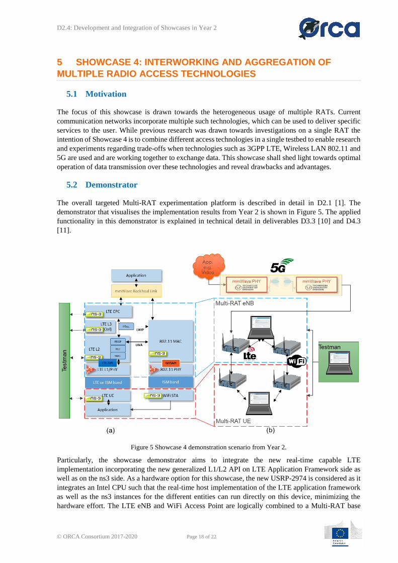
The overall targeted Multi-RAT experimentation platform is described in detail in D2.1 [1]. The
demonstrator that visualises the implementation results from Year 2 is shown in Figure 5. The applied
functionality in this demonstrator is explained in technical detail in deliverables D3.3 [10] and D4.3
[11].
Figure 5 Showcase 4 demonstration scenario from Year 2.
Particularly, the showcase demonstrator aims to integrate the new real-time capable LTE
implementation incorporating the new generalized L1/L2 API on LTE Application Framework side as
well as on the ns3 side. As a hardware option for this showcase, the new USRP-2974 is considered as it
integrates an Intel CPU such that the real-time host implementation of the LTE application framework
as well as the ns3 instances for the different entities can run directly on this device, minimizing the
hardware effort. The LTE eNB and WiFi Access Point are logically combined to a Multi-RAT base
Page 19
D2.4: Development and Integration of Showcases in Year 2
© ORCA Consortium 2017-2020 Page 19 of 22
station serving a virtual Multi-RAT UE. To reconfigure different parameters of the setup, a control PC
is used with the TestMan implementation for ns3 remote-control, which was implemented in Y2 and is
described in D4.3 [11].
To emphasize the possibility to integrate a mmWave link into the setup, in this scenario the 60GHz
mmWave system described in D3.1 and D3.3 is used as a back haul link. with the described functionality
from Section 2 to integrate Showcase 1 and 4. This can be seen as a first step towards integration of 5G
capable technology into the RAT interworking showcase as mmWave backhaul links will become
broadly available in cases where fiber connection of base stations to the core network are too costly to
be deployed.
With the setup of this showcase, experimenters can start diverse experiments, incorporating simple
networking examples and more involving interworking technologies such as LTE-WLAN Aggregation
(LWA) and LTE-WLAN radio level integration with IP security tunnel (LWIP).
5.3 Mapping to the ORCA KPIs
The Year 2 activities were focusing on further enhancing the data plane of the platform as well as the
introduction of a remote-control interface that will enable a split of data and control plane. Additionally,
the logical merge of LTE and WiFi devices in a single node of ns3 enables connectivity of a user terminal
over two different RATs. These two focus areas of Year 2 map directly to KPI 13 (Split of control and
data plane and dual connectivity of user terminal). The addition of RAT interworking techniques such
as LWA and LWIP in Year 2 through the Open Call 1 for Extension and the incorporation into the
overall Multi-RAT networking example have drawn insights into the interaction of two radio access
technologies and therefore map directly to KPI 14 (Interaction between two RATs to research where
and how legacy and 5G RAT need to exchange information).
5.4 Innovation Aspects
Main contributions & achievements
The main contribution of this showcase is the integration of multiple radio access and transmission
technologies into a single platform for experimentation. The LTE and WiFi systems are now completely
real-time capable and therefore closer to real stack implementations of the market. Furthermore, the E2E
capabilities shown in this Showcase allow for a diverse application involvement to understand the
influence of different applications on the transmission and usage of various RAT interworking strategies.
The remote control gives the experimenter two options at hand. First, simple reconfiguration of the
platform can be achieved. Secondly, the remote control can also be used to envisage simple SDN-type
of control experiments. Lastly, the introduction of support for the USRP-2974 is of great advantage as
it reduces the hardware footprint in the testbed.
Beyond the state-of-the-art
The showcase 4 claims to be the first prototyping and experimentation platform that involves
interworking between LTE and WiFi, with additional E2E inclusion of a 5G mmWave link. Such a
diverse setup was not made available before to do experiments. The anticipated gains of interworking
technologies that are shown in the literature can now be proven with real experiments. For such
scenarios, a fast adaption of the complete setup is needed. NI’s prototyping platform including latest
SDR technology with a streamlined toolflow, and the additional incorporation of ns3 as a widely used
network simulation environment, fulfil these constraints and equip researchers and experimenters with
the necessary tools.
Page 20
D2.4: Development and Integration of Showcases in Year 2
© ORCA Consortium 2017-2020 Page 20 of 22
5.5 Involved partner and their role
NI:
• Provides the Multi-RAT platform prototype setup for RAT interworking studies with 3GPP
LTE and 802.11:
o LabVIEW based real-time implementations of 3GPP LTE and 802.11 PHY layer
running on standalone USRPs or USRPs with PXI connection
o Real-time capable L1/L2 APIs for LTE and WiFi to interconnect 3GPP LTE and 802.11
PHY layers to the upper layers within ns3
o Ns3 extensions for networking examples as well as interworking technologies
(LWA/LWIP)
o Remote control of the setup via TestMan interface
TUD:
• Provides the mmWave link Physical layer and beamsteering MAC implementation with
necessary interfaces for E2E capabilities
5.6 Conclusion
Within Showcase 4 the goal is to gain insights into interworking techniques between multiple RATs
such as LTE, 802.11 as well as 5G. The described Year 2 platform allows for transmission using either
LTE or the Wifi system but also incorporates routing to a combined LTE/Wifi UE as well as
interworking strategies between these two radio access technologies using the latest real-time capable
implementation of the PHY layers. The incorporation of a mmWave link as a 5G backhaul option further
enhances the possibilities of experiments in the context of E2E application experiments involving
different transmission technologies. Lastly, remote control paves the way towards free orchestration of
the platform into the direction of SDN-like approaches.
Page 21
D2.4: Development and Integration of Showcases in Year 2
© ORCA Consortium 2017-2020 Page 21 of 22
6 CONCLUSIONS
In the deliverable D2.1 [1], ORCA defined four showcases that exemplify how the facilities can be
explored from a general viewpoint. Also, many functionalities were described in D2.2 [2] such that
ORCA capabilities can be easily consulted by interested third parties. Therefore, this document was
designed as a complement of D2.1 and D2.2, in which we report how the ORCA functionalities can be
explored in a more detailed and practical manner. In particular, Showcase 1 demonstrates a high
throughput mmWave system that can be configured in real-time in order to optimize the use of resources.
Showcase 2 targets at demonstrating spectrum sharing capability of ORCA SDRs applied to remotely
controlled robots while maintaining low latency link performance. Showcase 3 demonstrates the
coordination between SDN and SDRs, as well as the different types of radio slicing and virtualization
applied to different contexts. And finally, Showcase 4 aims to combine LTE and WiFi as well as 5G
type of links into a unified experimental platform for RAT interworking studies with E2E capabilities.
Page 22
D2.4: Development and Integration of Showcases in Year 2
© ORCA Consortium 2017-2020 Page 22 of 22
REFERENCES
[1] ORCA Deliverable D2.1, “Definition of showcases’’, March 2017.
[2] ORCA Deliverable D2.2, “D2.2: Technical Requirements of the ORCA Facility’’, July 2017.
[3] ORCA Deliverable D2.3, “D2.3: Development and Integration of Showcases in Year 1’’,
December 2017.
[4] T. S. Rappaport et al., “Millimeter Wave Mobile Communications for 5G Cellular: It Will
Work!,” in IEEE Access, vol. 1, no. , pp. 335-349, 2013.
[5] R. W. Heath, N. González-Prelcic, S. Rangan, W. Roh and A. M. Sayeed, “An Overview of
Signal Processing Techniques for Millimeter Wave MIMO Systems,” in IEEE Journal of
Selected Topics in Signal Processing, vol. 10, no. 3, pp. 436-453, April 2016.
[6] ORCA Deliverable D3.1, “First operational real-time SDR platforms”, December 2017
[7] Open vSwitch, https://www.openvswitch.org/, online, last accessed 2/12/2018
[8] MySVL, https://github.com/jvandebelt/gr-mysvl, online, last accessed 2/12/2018
[9] SDN-R, https://wiki.onap.org/display/DW/SDN-R+Objectives, online, last accessed 2/12/2018
[10] ORCA Deliverable D3.3, “Enhanced operational real-time SDR platforms”, December 2018
[11] ORCA Deliverable D4.3, “Enhanced operational SDR platforms with end-to-end capabilities”,
December 2018