1 Michael Floccare Casey Forman Ian Hochuli Kenneth Lopez DoRonne Shyu Dan Urban PolyurethaneGraphene Laminar Composite as Transparent Armour Abstract Current transparent armour requires a higher impact strength as well as maintaining visibility after impact. We propose the use of a graphenereinforced polyurethane laminar composite as a transparent protective material. This composite will allow for the production of lighter, thinner, and transparent under fire bullet resistant panels for use in military and private defense applications. We used VESTA, VASP, and DeepThought to investigate the elastic modulus of the laminar composite. We used ANSYS to run ballistic modeling on polyurethane and our composite system. Our model showed the addition of graphene reduced the kinetic energy of the projectile by an additional 30% compared to polyurethane alone. Motivation Bulletproof glass is used to protect personnel from incoming fire while maintaining visibility. The problem with current ceramicpolymeric composite technologies is crack and fracture upon impact [1]. This not only compromises visibility after sustaining a hit, but decreases the overall strength of the window. It also absorbs the bullets into the surface and introduces the possibility of collateral damage [1]. Polymers are an attractive material for bulletproof glass because of their resistance to crack propagation, and ability to melt and reseal around the path of the projectile as it impacts the surface and passes through the bulk [2]. Polyurethane exhibits the abilities of remaining transparent and encapsulating the projectile when struck. We propose the use of a graphene reinforced polyurethane media as a transparent protective material to create a transparent laminated composite with graphene to reinforce the polyurethane. This will allow for the production of lighter, thinner, and transparent under fire bullet resistant panels for use in military and private defense applications. Previous Work The most common design for bulletresistant transparent armour consists of alternating layers of glass, and polycarbonate [2]. The glass acts as a hard shell, deforming the bullet and slowing it down considerably. The polycarbonate acts as a shock absorber and dissipates the projectile energy while simultaneously enhancing the glass’s fracture
Transcript
1
Michael Floccare Casey Forman Ian Hochuli Kenneth Lopez DoRonne Shyu Dan Urban
Polyurethane-‐Graphene Laminar Composite as Transparent Armour Abstract Current transparent armour requires a higher impact strength as well as maintaining visibility after impact. We propose the use of a graphene-‐reinforced polyurethane laminar composite as a transparent protective material. This composite will allow for the production of lighter, thinner, and transparent under fire bullet resistant panels for use in military and private defense applications. We used VESTA, VASP, and DeepThought to investigate the elastic modulus of the laminar composite. We used ANSYS to run ballistic modeling on polyurethane and our composite system. Our model showed the addition of graphene reduced the kinetic energy of the projectile by an additional 30% compared to polyurethane alone. Motivation Bulletproof glass is used to protect personnel from incoming fire while maintaining visibility. The problem with current ceramic-‐polymeric composite technologies is crack and fracture upon impact [1]. This not only compromises visibility after sustaining a hit, but decreases the overall strength of the window. It also absorbs the bullets into the surface and introduces the possibility of collateral damage [1]. Polymers are an attractive material for bulletproof glass because of their resistance to crack propagation, and ability to melt and reseal around the path of the projectile as it impacts the surface and passes through the bulk [2]. Polyurethane exhibits the abilities of remaining transparent and encapsulating the projectile when struck. We propose the use of a graphene reinforced polyurethane media as a transparent protective material to create a transparent laminated composite with graphene to reinforce the polyurethane. This will allow for the production of lighter, thinner, and transparent under fire bullet resistant panels for use in military and private defense applications. Previous Work The most common design for bullet-‐resistant transparent armour consists of alternating layers of glass, and polycarbonate [2]. The glass acts as a hard shell, deforming the bullet and slowing it down considerably. The polycarbonate acts as a shock absorber and dissipates the projectile energy while simultaneously enhancing the glass’s fracture
2
toughness. The various layer thicknesses and total number of layers are dictated by the caliber of the bullet you wish to shield against [3]. To improve upon this pre-‐existing technology, we have proposed the use of graphene-‐reinforced polyurethane. Previous groups, to our knowledge, have not yet studied polyurethane's specific microstructure and ballistic impact characteristics. Work has been done to model the underlying mechanisms with polystyrene/PDMS block copolymer [4]. The polystyrene was used to model the stiff crystalline regions of polyurethane, and the PDMS was used to simulate the rubbery amorphous regions of polyurethane. There have also been studies performed to test the ballistic characteristics of graphene [5]. This research found that graphene had the highest ballistic resistance per thickness which makes it an extraordinary armour material exhibiting excellent impact energy delocalization under a high-‐speed penetration event [5]. Based upon these findings, researchers then showed that the addition of graphene platelets to a polyurethane matrix will strengthen its ballistic characteristics. Design Goals We looked to design the composite to have at least 90% transmittance after impact (with setting 100% transmittance before impact and at least 98% transmittance after application of graphene). As well as the composite seeing at least a 10% increase in impact strength with the addition of graphene layers. To reach these goals, we first looked at the interaction between graphene and polyurethane, then the impact resistance of the composite. This is discussed in the subsequent sections. Technical Approach Chemical Modeling: We started chemical modeling by generating computer models of both the graphene structure and the polyurethane molecules by utilizing VESTA and the Materials Project Python files. Figure 1 shows a graphene sheet with a single hydrogen atom attached. Figure 2 shows a single polyurethane unit. Our models depict the correct bond lengths, bond angles, and configurations.
3
Figure 1: Graphene sheet with oxygen atom attached created in VESTA
Figure 2: Polyurethane segment created in VESTA
The next stage of the chemical modeling process was completing the energy minimization using density functional theory (DFT) to find the equivalent spring constant of the bond between hydrogen(s) on the polymer with an oxygen atom attached on the graphene layer. We modeled only a single oxygen atom because the oxygen atoms will be far enough apart (infinitely far apart) that there will be no interference between them. With this spring constant, we can model the graphene with an attached oxygen atom as a sheet with a fixed effective spring constant. This fixed value is the summation of the spring constants of the bond between hydrogen on the polymer interface with oxygen of the graphene layer (since the bonds are parallel to each other) as in Figure 3.
4
Figure 3: Basic idea of modeling the PU/graphene spring constant
Thus, in a simple 1D model, we can would have essentially three layers (polymer bonded to the oxygen bonded to the graphene) in series with different spring constants. We will be able to determine an effective spring constant for the entire system (the summation of the 3 different spring constants) and this will reduce down to a single layer with an effective spring constant which we can replace with a modulus that represents the entire system. We will be able to do ballistic modeling and simple penetration depth modeling with this “new” layer. Ballistic Modeling: In order to ensure a feasible results from our model, we first focused on correctly modeling a simple Hertzian contact penetration depth in ANSYS Workbench. The model will incorporate the relevant materials to our project, lead and polyurethane, and the results will be compared to the calculated value. We are using classical Hertzian contact mechanics to model the simplest case: a sphere in contact with a semi-‐infinite slab under constant loading conditions. To ensure that the boundary effects are eliminated, the modeled slab is 50-‐times larger than the radius of the sphere in the x, y, and z directions. The penetration depth (d) depends on the contact area (a), reduced elastic modulus (E*), applied load (F), and sphere radius (R), shown in the Equation 1:
d=a2/R = (9F2/16RE*2)⅓ (1) This model makes several assumptions such as: the strains on both bodies are small so all deformation is elastic and that the area of contact is much smaller than the characteristic dimensions of the contacting bodies. Both of these can be maintained as long as the applied load is kept sufficiently small (1N in our analysis). The third assumption is addressed by the drastically large slab.
5
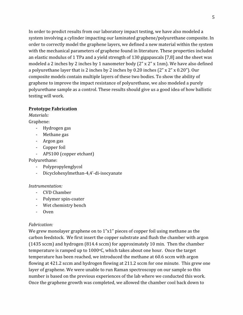
In order to predict results from our laboratory impact testing, we have also modeled a system involving a cylinder impacting our laminated graphene/polyurethane composite. In order to correctly model the graphene layers, we defined a new material within the system with the mechanical parameters of graphene found in literature. These properties included an elastic modulus of 1 TPa and a yield strength of 130 gigapascals [7,8] and the sheet was modeled a 2 inches by 2 inches by 1 nanometer body (2” x 2” x 1nm). We have also defined a polyurethane layer that is 2 inches by 2 inches by 0.20 inches (2” x 2” x 0.20”). Our composite models contain multiple layers of these two bodies. To show the ability of graphene to improve the impact resistance of polyurethane, we also modeled a purely polyurethane sample as a control. These results should give us a good idea of how ballistic testing will work. Prototype Fabrication Materials: Graphene:
-‐ Hydrogen gas -‐ Methane gas -‐ Argon gas -‐ Copper foil -‐ APS100 (copper etchant)
Fabrication: We grew monolayer graphene on to 1”x1” pieces of copper foil using methane as the carbon feedstock. We first insert the copper substrate and flush the chamber with argon (1435 sccm) and hydrogen (814.4 sccm) for approximately 10 min. Then the chamber temperature is ramped up to 1000oC, which takes about one hour. Once the target temperature has been reached, we introduced the methane at 60.6 sccm with argon flowing at 421.2 sccm and hydrogen flowing at 211.2 sccm for one minute. This grew one layer of graphene. We were unable to run Raman spectroscopy on our sample so this number is based on the previous experiences of the lab where we conducted this work. Once the graphene growth was completed, we allowed the chamber cool back down to
6
below 150oC before opening and removing the copper foil with the newly grown graphene from the chamber and shut down the entire system. This whole process took about 2.5 hours. The transfer process is done in sequential steps, shown in Figure 4-‐-‐the addition of the PU and then the removal of the graphene underlayer and copper. We first spin-‐coated 3 drops of PU onto the CVD-‐grown graphene on copper foil at 4500rpm for 45 sec; then the PU is cured at 150oC for 20min. Removing the copper from the graphene required that we first etch the graphene underlayer in 20 mL of ammonium persulfate for about 1 minute in a small flat beaker. Once the graphene underlayer was removed, we inserted a glass slide underneath the sample to remove it from the etchant and placed the sample onto the surface of clean etchant in another flat beaker. We etched the exposed copper foil in 40 mL of ammonium persulfate for 2-‐3 hours (depending on the size of substrate) in this large flat beaker. For this entire etching process, it is important that the sample is floating on the etchant and not submerged. After this process, we had graphene attached to the PU. We allowed let the sample air dry on the glass slide. Once the sample is dry, we first apply another PU layer onto the graphene/PU and then attach another graphene/PU sample onto the uncured PU, such that there are 5 total layers in the composite. Then laminar composite must be cured at 150oC for 20min.
Figure 4: Summary of processing steps to fabricate the composite (lighter red indicates
uncured PU, dark red indicates cured PU)
7
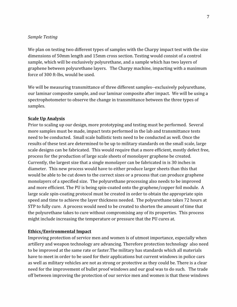
Sample Testing We plan on testing two different types of samples with the Charpy impact test with the size dimensions of 50mm length and 15mm cross section. Testing would consist of a control sample, which will be exclusively polyurethane, and a sample which has two layers of graphene between polyurethane layers. The Charpy machine, impacting with a maximum force of 300 ft-‐lbs, would be used. We will be measuring transmittance of three different samples-‐-‐exclusively polyurethane, our laminar composite sample, and our laminar composite after impact. We will be using a spectrophotometer to observe the change in transmittance between the three types of samples. Scale Up Analysis Prior to scaling up our design, more prototyping and testing must be performed. Several more samples must be made, impact tests performed in the lab and transmittance tests need to be conducted. Small scale ballistic tests need to be conducted as well. Once the results of these test are determined to be up to military standards on the small scale, large scale designs can be fabricated. This would require that a more efficient, mostly defect free, process for the production of large scale sheets of monolayer graphene be created. Currently, the largest size that a single monolayer can be fabricated in is 30 inches in diameter. This new process would have to either produce larger sheets than this that would be able to be cut down to the correct sizes or a process that can produce graphene monolayers of a specified size. The polyurethane processing also needs to be improved and more efficient. The PU is being spin-‐coated onto the graphene/copper foil module. A large scale spin-‐coating protocol must be created in order to obtain the appropriate spin speed and time to achieve the layer thickness needed. The polyurethane takes 72 hours at STP to fully cure. A process would need to be created to shorten the amount of time that the polyurethane takes to cure without compromising any of its properties. This process might include increasing the temperature or pressure that the PU cures at. Ethics/Environmental Impact Improving protection of service men and women is of utmost importance, especially when artillery and weapon technology are advancing. Therefore protection technology also need to be improved at the same rate or faster.The military has standards which all materials have to meet in order to be used for their applications but current windows in police cars as well as military vehicles are not as strong or protective as they could be. There is a clear need for the improvement of bullet proof windows and our goal was to do such. The trade off between improving the protection of our service men and women is that these windows
8
are not great for the environment. Polyurethane is a plastic, which means that it cannot be readily recycled into new windows. The other issue that is presented with this new technology is that by sandwiching graphene between the layers of polyurethane the recycling process becomes much more challenging. If the graphene can be extracted from the polyurethane, it can be reused in several different ways ranging from battery anodes to lubricants for metal-‐metal joints. This technology will benefit more than just our military and police men and women. If this technology proves useful and beats the current standards, it could be and should be put into use in buildings which house our world leaders such as embassies both here in the United States as well as other countries. We also think that this technology could prove more useful for ballistic shields like those that the SWAT teams use. The current design for these ballistic shields is a large metal and/or Kevlar plate with a small window cut out from the top middle section. If this technology improve bullet resistance better than the current technology, the SWAT teams could not only see through the entire shield to their attacker but also have a constant visual if their shield is hit. Materials used in the fabrication of the prototype include various inert gases for stabilizing the CVD chamber, carbon feedstock, copper substrate, polymer, and copper etchant. Methane is the carbon feedstock; it is flammable and as a compressed gas may cause explosions. Hydrogen is also flammable, an asphyxiant, and as compressed gas may cause explosions. Argon is also an asphyxiant and compressed gas may cause explosions. Polyurethane presents no significant hazard. Copper is hazardous upon ingestion and inhalation; once it has been dissolved in etchant, it goes down drain in the FabLab. We will be using approximately a square inch of copper foil at a time. The copper etchant being used is APS-‐100, which is a strong oxidizer and will disposed down the acid drain in FabLab where it will be neutralized; we will be using approximately 60 mL/run. This composite should last until the polymer starts to degrade. The polyurethane is UV stable so it will not degrade or change color when exposed to the sun for long periods of time. If the composite is hit by [a] bullet(s) before the polymer starts to degrade, the replacement of the window is up to the discretion of the driver, persons being protected, etc. The window should be replaced shortly after being struck by a bullet to account for the diminished mechanical properties which occur after impact. The more times the window is struck, the sooner the window should be replaced. These worn out devices can be “downcycled” into several different devices and structures including park benches and other structure, where small pieces of material can be shaped or pressed into something new.
9
Results With Water Clear Polyurethane from EasyComposites, we were able to construct the polyurethane model by combining polypropyleneglycol and dicyclohexylmethan-‐4,4'-‐di-‐isocyanate to form the polyurethane repeat unit (Figure 2). From this model, we ran energy minimization simulations on the DeepThought. The results showed that our polyurethane model had bonded to one of the unsatisfied carbon bonds on the graphene sheets Figure 5.
Figure 5: Bonding of PU to unsatisfied graphene platelet
We extended the graphene platelet to a sheet so that the bonding between the graphene and polyurethane will occur on the oxygen attached to the graphene sheet rather than the carbon atom (Figure 6). Once we successfully get bonding to the oxygen atom on the graphene sheet, we will be able to determine the spring constant of the bond using a Newtonian mechanics calculation of molecular vibrations.
Figure 6: 3D model of graphene sheet with polyurethane molecule
10
We attempted to confirm our chemical model bonding scheme between graphene and the polyurethane. We hypothesised that this would show that the dangling hydrogen bonds from the polyurethane would bond to the oxygen atom attached to the graphene layer. Once we determined the bonding, we planned to determine an equilibrium bond distance through energy minimization calculations. We would then perform energy calculations at distances of ±5 angstroms from equilibrium to establish energy vs. distance behavior of the bond. We would then use a parabolic fit to find the interfacial spring constant:
E=½ kx2 (2)
where E is energy, k is spring constant, and x is distance away from equilibrium. Using Hooke’s Law (Equation 3) we can then relate spring constant to elastic modulus with Equation 4:
F=-‐kx (3)
λ=-‐kx/A (4)
where F is force, k is spring constant, x is distance away from equilibrium, λ is elastic modulus, and A is area. Due to time constraint, we were unable to perform these calculations on a full sheet of graphene shown in Figure 6.
The initial results for our ballistic testing come from our Hertzian mechanics test, an example of which is shown in Figure 7. In this test, we found a penetration depth, d, of 5.619 μm, compared to the ideal value of 5.518 μm, this is a 1E-‐7 μm difference, and a 1.83% error. This gave us the confidence to use ANSYS and move forward with impact simulations.
Our impact simulation modeled a one-‐inch thick polyurethane block with four graphene sheets equally spaced throughout the composite. In this simulation we found an energy reduction from 469.74 J to 386.49 J (83.25 J change). In comparison to the energy reduction of 62.88 J from a one-‐inch block of polyurethane, this is a 32% increase in energy reduction
11
with the addition of graphene. The increased amount of energy reduction from graphene inclusion shown in Figure 8, is the most significant result from the ANSYS modeling.
Figure 8: Kinetic energy of the bullet as it progresses through the five-‐layer composite (blue)
and polyurethane-‐only specimens (red).
During fabrication, we decided to test the polyurethane’s resistance to our copper etchant. We wanted to see if it was possible to spin coat the PU on to our graphene/copper foil module without using an intermediate; therefore, we needed to make sure it was resistant to the etchant. It was determined that the polyurethane is resistant to the APS100 copper etchant. From here, would like to perform several tests to determine the optimal time, the spin speed, and the initial volume to spin coat the polyurethane. Due to time constraints we were unable to test our spin coating methods.
If given more time, we would like to refine our ballistics model by implementing a numerical method to calculate energy reduction errors. Also, we would construct an imperfect graphene sheet to account for grain boundary effects to make a more accurate ballistics model. Furthermore, we would like to test our prototype as well as fabricate a prototype using military grade materials to meet ballistic standards for transparent armour. Intellectual Merit This project will study the surface chemistry, mechanical properties and optical properties of the functionalization of graphene to polyurethane. To our knowledge, the effect of the addition of graphene between layers of polyurethane as a bulletproof shield has not yet been studied. Polyurethane has been recently been applied as a transparent bulletproof coating for glass [9], but there is not much data on the bullet resistance of polyurethane itself. This needs to be determined in order to understand if these windows will be, in fact, bulletproof. The dispersion dynamics of this window when it is hit by a bullet are also not
12
known. We must determine how this window will react when it is struck to make sure that there is no damage done to whatever is behind the window. This project will further the knowledge on the impact resistance for polyurethane and how the addition of a graphene layer affects polyurethane. It will be the first known study of how the addition of a graphene layer affects the impact resistance of polyurethane. Broader Impact From this work, we hope to spark more interest in the research and development of graphene-‐reinforced polymeric system for high impact resistance. Also, due to the fact that polyurethane is lighter than the current glass composite, this window would be useful in creating lighter weight vehicles therefore improving fuel efficiency and reducing the world’s carbon footprint. This composite would reduce collateral damage because it would not shatter or cause the bullet to ricochet. Conclusion From our ballistics model, we have shown that the inclusion of graphene to polyurethane shows a further reduction in the kinetic energy of the bullet compared to just polyurethane. A composite with five layers of polyurethane and four layers of graphene will reduce the kinetic energy of the bullet by 32% more than a polyurethane sample with comparable dimensions. We have developed a low-‐cost method to fabricate and characterize a lab-‐scale prototype. By using iterative steps of CVD, spin coating, and etching, a laminar structure with minimal defects can be fabricated. The charpy test and spectrophotometer would give impact strength and transmittance data, respectively, allowing for quantifiable comparison to military standards. Our design and modeling show that this composite could be a promising material to improve optical transmittance after impact as well as the impact strength for transparent armour. Acknowledgements We would like to thank Dr. Jon Cumings for letting us use his lab free of charge to grow graphene, Jeremy Ticey for teaching us how to grow graphene and perform graphene transfer, Dr. Ray Phaneuf for guiding us through our project, Dr. Tim Foecke for lending us a dessicator to cure the polyurethane, Jon Mecham for helping us with DeepThought simulations, Ginette Villeneuve for ordering materials for us in a timely manner, Dr. Gary Rubloff for providing insight on CVD and graphene transfer, Dr. Mo for providing insight into DeepThought simulations, Dr. Steven Kilczewski from the ARL for his support, Steven Lacey for insight into chemical modeling, FabLab staff for their support, and the MSE staff for their teachings and continued support.
13
Cited Works: [1] Wu, Huang, Wang, Wu, Yang, Li, Jiang. Hyperbranched-‐polymer functionalization of graphene sheets for enhanced mechanical and dielectric properties of polyurethane composites. 2012, 7010-‐7019. J. Mater. Chem., 22, 14. [2] Njoroge, Jean L. Atomistic Simulation of Graphene-‐Polyurethane Nanocomposite for Use in Ballistic Applications. 2012, Doctoral dissertation, Texas A & M University. http : / /hdl .handle .net /1969 .1 /151360. [3] Total Security Solutions. How is Bullet Proof Glass Made? 19, Nov. 2009. http://www.tssbulletproof.com/how-‐is-‐bulletproof-‐glass-‐made/ [4] Lee J.-‐H. et al., High strain rate deformation of layered nanocomposites, Nat. Commun. 3:1164 doi: 10.1038/ncomms2166 (2012).http://www.nature.com/ncomms/journal/v3/n10/full/ncomms2166.html [5] Lee, Jae-‐Hwang, et al. "Dynamic mechanical behavior of multilayer graphene via supersonic projectile penetration." Science 346.6213 (2014): 1092-‐1096. [6] Automotive Tank Purchase Description ATPD 2352, Transparent Armor, Revision R, (U.S. Army, 26 April 2010) [7] Military Detail Specification MIL-‐DTL-‐11352, Block, vision: Bullet-‐resistant, Revision K, (Tank Automotive Research, Development and Engineering Center, 01 April 2013) [8] Lee, Changgu, et al. "Measurement of the elastic properties and intrinsic strength of monolayer graphene." science 321.5887 (2008): 385-‐388. [9] Liu, Xiao, et al. "Shear modulus of monolayer graphene prepared by chemical vapor deposition." Nano letters 12.2 (2012): 1013-‐1017. [10] Toqueboeuf, W., Mortaigne, B., & Cottenot, C. (1997). Dynamic Behaviour of Polycarbonate/Polyurethane Multi-‐Layer for Transparent Armor. Le Journal De Physique IV, C3-‐504. References: Gale. General Utility Lattice Program. Nanochemistry research Institute. http://citeseerx.ist.psu.edu/viewdoc/download?doi=10.1.1.332.9343&rep=rep1&type=pdf
14
Cheng, Grest. Molecular dynamics simulations of evaporation-‐induced nanoparticle assembly. J Chem Phys, 2013, 138, 064701 . ANSYS AUTODYN in Workbench. Ansys, inc. Nov. 2009, 12.1 http://orange.engr.ucdavis.edu/Documentation12.1/121/wb_adyn.pdf Stankovich, Dikin, Piner. Synthesis of graphene-‐based nanosheets via chemical reduction of exfoliated graphite oxide. Carbon v. 45, n.7, 2007, 1558 -‐ 1565. American Society for Testing and Materials ASTM F1233, Standard Test Method for Security Glazing Materials and Systems, Revision 08, (ASTM, 2013) Jianguo Song, Xinzhi Wang, and Chang-‐Tang Chang, “Preparation and Characterization of Graphene Oxide,” Journal of Nanomaterials, vol. 2014, Article ID 276143, 6 pages, 2014. doi:10.1155/2014/276143