96
GRAPHISOFT EcoDesigner User Guide

GRAPHISOFT EcoDesigner User Guide

GRAPHISOFT®
Visit the GRAPHISOFT website at http://www.graphisoft.com for local distributor and product availability information.
GRAPHISOFT EcoDesigner™ User GuideCopyright © 2011 by GRAPHISOFT, all rights reserved. Reproduction, paraphrasing or translation without
express prior written permission is strictly prohibited.
TrademarksArchiCAD® is a registered trademark of GRAPHISOFT.
All other trademarks are the property of their respective holders.
Contents
ContentsNote: The titles of chapters that contain additional information, intended for advanced users, are written in green.
Overview . . . . . . . . . . . . . . . . . . . . . . . . . . . . . . . . . . . . . . . . . . . . . . . . . . . . . . . . . . . . . . . . . . . . . . . . . . . . . . . . . . . . . . . . . . . . . . 7EcoDesigner Workflow . . . . . . . . . . . . . . . . . . . . . . . . . . . . . . . . . . . . . . . . . . . . . . . . . . . . . . . . . . . . . . . . . . . . . . . . . . . . . . . . . . . 7New Features in EcoDesigner for ArchiCAD 15 . . . . . . . . . . . . . . . . . . . . . . . . . . . . . . . . . . . . . . . . . . . . . . . . . . . . . . . . . . . . . . . 8
New Building Energy Evaluation Report . . . . . . . . . . . . . . . . . . . . . . . . . . . . . . . . . . . . . . . . . . . . . . . . . . . . . . . . . . . . . . . . . . . 8Energy Balance Excel Workbook . . . . . . . . . . . . . . . . . . . . . . . . . . . . . . . . . . . . . . . . . . . . . . . . . . . . . . . . . . . . . . . . . . . . . . . . . 9Data Export to Passivhaus Energy Calculator . . . . . . . . . . . . . . . . . . . . . . . . . . . . . . . . . . . . . . . . . . . . . . . . . . . . . . . . . . . . . . 9
Function Enhancements in EcoDesigner for ArchiCAD 15 . . . . . . . . . . . . . . . . . . . . . . . . . . . . . . . . . . . . . . . . . . . . . . . . . . . . . . 10Definitions . . . . . . . . . . . . . . . . . . . . . . . . . . . . . . . . . . . . . . . . . . . . . . . . . . . . . . . . . . . . . . . . . . . . . . . . . . . . . . . . . . . . . . . . . . . 10Getting Started With EcoDesigner . . . . . . . . . . . . . . . . . . . . . . . . . . . . . . . . . . . . . . . . . . . . . . . . . . . . . . . . . . . . . . . . . . . . . . . 22
Hardware/Software Requirements . . . . . . . . . . . . . . . . . . . . . . . . . . . . . . . . . . . . . . . . . . . . . . . . . . . . . . . . . . . . . . . . . . . . . . . 22File Compatibility . . . . . . . . . . . . . . . . . . . . . . . . . . . . . . . . . . . . . . . . . . . . . . . . . . . . . . . . . . . . . . . . . . . . . . . . . . . . . . . . . . . 22Licenses . . . . . . . . . . . . . . . . . . . . . . . . . . . . . . . . . . . . . . . . . . . . . . . . . . . . . . . . . . . . . . . . . . . . . . . . . . . . . . . . . . . . . . . . . . . 22Installation . . . . . . . . . . . . . . . . . . . . . . . . . . . . . . . . . . . . . . . . . . . . . . . . . . . . . . . . . . . . . . . . . . . . . . . . . . . . . . . . . . . . . . . . . 23Program Folder Location . . . . . . . . . . . . . . . . . . . . . . . . . . . . . . . . . . . . . . . . . . . . . . . . . . . . . . . . . . . . . . . . . . . . . . . . . . . . . 23Uninstall . . . . . . . . . . . . . . . . . . . . . . . . . . . . . . . . . . . . . . . . . . . . . . . . . . . . . . . . . . . . . . . . . . . . . . . . . . . . . . . . . . . . . . . . . . . 23Calculation Unit Settings . . . . . . . . . . . . . . . . . . . . . . . . . . . . . . . . . . . . . . . . . . . . . . . . . . . . . . . . . . . . . . . . . . . . . . . . . . . . . . 23Localized EcoDesigner Contents – the XML Files . . . . . . . . . . . . . . . . . . . . . . . . . . . . . . . . . . . . . . . . . . . . . . . . . . . . . . . . . . 24Folders Used by EcoDesigner . . . . . . . . . . . . . . . . . . . . . . . . . . . . . . . . . . . . . . . . . . . . . . . . . . . . . . . . . . . . . . . . . . . . . . . . . . 25
Working with EcoDesigner . . . . . . . . . . . . . . . . . . . . . . . . . . . . . . . . . . . . . . . . . . . . . . . . . . . . . . . . . . . . . . . . . . . . . . . . . . . . . . 26Automatic Model Analysis . . . . . . . . . . . . . . . . . . . . . . . . . . . . . . . . . . . . . . . . . . . . . . . . . . . . . . . . . . . . . . . . . . . . . . . . . . . . . . . 28Model Review . . . . . . . . . . . . . . . . . . . . . . . . . . . . . . . . . . . . . . . . . . . . . . . . . . . . . . . . . . . . . . . . . . . . . . . . . . . . . . . . . . . . . . . . . 30
Changing Mark-Up Colors . . . . . . . . . . . . . . . . . . . . . . . . . . . . . . . . . . . . . . . . . . . . . . . . . . . . . . . . . . . . . . . . . . . . . . . . . . . . 31Modify Element’s Building Structure Group . . . . . . . . . . . . . . . . . . . . . . . . . . . . . . . . . . . . . . . . . . . . . . . . . . . . . . . . . . . . . . . 32Adiabatic Walls of the Building Shell . . . . . . . . . . . . . . . . . . . . . . . . . . . . . . . . . . . . . . . . . . . . . . . . . . . . . . . . . . . . . . . . . . . . 32
GRAPHISOFT EcoDesigner User Guide 3
Contents
Shell Slabs . . . . . . . . . . . . . . . . . . . . . . . . . . . . . . . . . . . . . . . . . . . . . . . . . . . . . . . . . . . . . . . . . . . . . . . . . . . . . . . . . . . . . . . . . 33Select Elements . . . . . . . . . . . . . . . . . . . . . . . . . . . . . . . . . . . . . . . . . . . . . . . . . . . . . . . . . . . . . . . . . . . . . . . . . . . . . . . . . . . . . 33Show/Hide Building Volume . . . . . . . . . . . . . . . . . . . . . . . . . . . . . . . . . . . . . . . . . . . . . . . . . . . . . . . . . . . . . . . . . . . . . . . . . . . . 34Customizing the Building Volume Display . . . . . . . . . . . . . . . . . . . . . . . . . . . . . . . . . . . . . . . . . . . . . . . . . . . . . . . . . . . . . . . . . 35Reanalyze Model . . . . . . . . . . . . . . . . . . . . . . . . . . . . . . . . . . . . . . . . . . . . . . . . . . . . . . . . . . . . . . . . . . . . . . . . . . . . . . . . . . . . 35Back to EcoDesigner . . . . . . . . . . . . . . . . . . . . . . . . . . . . . . . . . . . . . . . . . . . . . . . . . . . . . . . . . . . . . . . . . . . . . . . . . . . . . . . . . 36
Additional User Input . . . . . . . . . . . . . . . . . . . . . . . . . . . . . . . . . . . . . . . . . . . . . . . . . . . . . . . . . . . . . . . . . . . . . . . . . . . . . . . . . . . 36Location and Function . . . . . . . . . . . . . . . . . . . . . . . . . . . . . . . . . . . . . . . . . . . . . . . . . . . . . . . . . . . . . . . . . . . . . . . . . . . . . . . . . . . 37
Report Header . . . . . . . . . . . . . . . . . . . . . . . . . . . . . . . . . . . . . . . . . . . . . . . . . . . . . . . . . . . . . . . . . . . . . . . . . . . . . . . . . . . . . . 38Project Location . . . . . . . . . . . . . . . . . . . . . . . . . . . . . . . . . . . . . . . . . . . . . . . . . . . . . . . . . . . . . . . . . . . . . . . . . . . . . . . . . . . . . 38Climate Files . . . . . . . . . . . . . . . . . . . . . . . . . . . . . . . . . . . . . . . . . . . . . . . . . . . . . . . . . . . . . . . . . . . . . . . . . . . . . . . . . . . . . . . 39Grade Level to Project Zero . . . . . . . . . . . . . . . . . . . . . . . . . . . . . . . . . . . . . . . . . . . . . . . . . . . . . . . . . . . . . . . . . . . . . . . . . . . . 40Wind Protection . . . . . . . . . . . . . . . . . . . . . . . . . . . . . . . . . . . . . . . . . . . . . . . . . . . . . . . . . . . . . . . . . . . . . . . . . . . . . . . . . . . . . 41Surroundings . . . . . . . . . . . . . . . . . . . . . . . . . . . . . . . . . . . . . . . . . . . . . . . . . . . . . . . . . . . . . . . . . . . . . . . . . . . . . . . . . . . . . . . 41Facade Shadings . . . . . . . . . . . . . . . . . . . . . . . . . . . . . . . . . . . . . . . . . . . . . . . . . . . . . . . . . . . . . . . . . . . . . . . . . . . . . . . . . . . . 41Custom Façade Shadings . . . . . . . . . . . . . . . . . . . . . . . . . . . . . . . . . . . . . . . . . . . . . . . . . . . . . . . . . . . . . . . . . . . . . . . . . . . . . . 42Activity . . . . . . . . . . . . . . . . . . . . . . . . . . . . . . . . . . . . . . . . . . . . . . . . . . . . . . . . . . . . . . . . . . . . . . . . . . . . . . . . . . . . . . . . . . . . 43Custom Activity Profiles . . . . . . . . . . . . . . . . . . . . . . . . . . . . . . . . . . . . . . . . . . . . . . . . . . . . . . . . . . . . . . . . . . . . . . . . . . . . . . . 45
Structures . . . . . . . . . . . . . . . . . . . . . . . . . . . . . . . . . . . . . . . . . . . . . . . . . . . . . . . . . . . . . . . . . . . . . . . . . . . . . . . . . . . . . . . . . . . . . 46Building Shell Elements . . . . . . . . . . . . . . . . . . . . . . . . . . . . . . . . . . . . . . . . . . . . . . . . . . . . . . . . . . . . . . . . . . . . . . . . . . . . . . . 47Surface . . . . . . . . . . . . . . . . . . . . . . . . . . . . . . . . . . . . . . . . . . . . . . . . . . . . . . . . . . . . . . . . . . . . . . . . . . . . . . . . . . . . . . . . . . . . 49Infiltration . . . . . . . . . . . . . . . . . . . . . . . . . . . . . . . . . . . . . . . . . . . . . . . . . . . . . . . . . . . . . . . . . . . . . . . . . . . . . . . . . . . . . . . . . 50U-value (R-value) Calculator . . . . . . . . . . . . . . . . . . . . . . . . . . . . . . . . . . . . . . . . . . . . . . . . . . . . . . . . . . . . . . . . . . . . . . . . . . 51U-value (R-value) Calculation Algorithm . . . . . . . . . . . . . . . . . . . . . . . . . . . . . . . . . . . . . . . . . . . . . . . . . . . . . . . . . . . . . . . . . 52Thermal Property Assignment . . . . . . . . . . . . . . . . . . . . . . . . . . . . . . . . . . . . . . . . . . . . . . . . . . . . . . . . . . . . . . . . . . . . . . . . . . 53Default Thermal Property Assignments . . . . . . . . . . . . . . . . . . . . . . . . . . . . . . . . . . . . . . . . . . . . . . . . . . . . . . . . . . . . . . . . . . . 55U-value Override . . . . . . . . . . . . . . . . . . . . . . . . . . . . . . . . . . . . . . . . . . . . . . . . . . . . . . . . . . . . . . . . . . . . . . . . . . . . . . . . . . . . 55Material Catalog . . . . . . . . . . . . . . . . . . . . . . . . . . . . . . . . . . . . . . . . . . . . . . . . . . . . . . . . . . . . . . . . . . . . . . . . . . . . . . . . . . . . 57
4 GRAPHISOFT EcoDesigner User Guide
Contents
Customizing the Material Catalog . . . . . . . . . . . . . . . . . . . . . . . . . . . . . . . . . . . . . . . . . . . . . . . . . . . . . . . . . . . . . . . . . . . . . . . 58Building Geometry . . . . . . . . . . . . . . . . . . . . . . . . . . . . . . . . . . . . . . . . . . . . . . . . . . . . . . . . . . . . . . . . . . . . . . . . . . . . . . . . . . . 59Internal Heat Storage Mass . . . . . . . . . . . . . . . . . . . . . . . . . . . . . . . . . . . . . . . . . . . . . . . . . . . . . . . . . . . . . . . . . . . . . . . . . . . . 60Underground Insulation . . . . . . . . . . . . . . . . . . . . . . . . . . . . . . . . . . . . . . . . . . . . . . . . . . . . . . . . . . . . . . . . . . . . . . . . . . . . . . . 60Advanced Handling of Underground Insulation . . . . . . . . . . . . . . . . . . . . . . . . . . . . . . . . . . . . . . . . . . . . . . . . . . . . . . . . . . . . 61
Openings . . . . . . . . . . . . . . . . . . . . . . . . . . . . . . . . . . . . . . . . . . . . . . . . . . . . . . . . . . . . . . . . . . . . . . . . . . . . . . . . . . . . . . . . . . . . . 62Shading Devices . . . . . . . . . . . . . . . . . . . . . . . . . . . . . . . . . . . . . . . . . . . . . . . . . . . . . . . . . . . . . . . . . . . . . . . . . . . . . . . . . . . . . 64Custom Shading Devices . . . . . . . . . . . . . . . . . . . . . . . . . . . . . . . . . . . . . . . . . . . . . . . . . . . . . . . . . . . . . . . . . . . . . . . . . . . . . . 64Openings Catalog . . . . . . . . . . . . . . . . . . . . . . . . . . . . . . . . . . . . . . . . . . . . . . . . . . . . . . . . . . . . . . . . . . . . . . . . . . . . . . . . . . . 66Customizing the Openings Catalog . . . . . . . . . . . . . . . . . . . . . . . . . . . . . . . . . . . . . . . . . . . . . . . . . . . . . . . . . . . . . . . . . . . . . . 67
MEP Systems and Energy . . . . . . . . . . . . . . . . . . . . . . . . . . . . . . . . . . . . . . . . . . . . . . . . . . . . . . . . . . . . . . . . . . . . . . . . . . . . . . . . 68Energy Source . . . . . . . . . . . . . . . . . . . . . . . . . . . . . . . . . . . . . . . . . . . . . . . . . . . . . . . . . . . . . . . . . . . . . . . . . . . . . . . . . . . . . . 68Heating Type . . . . . . . . . . . . . . . . . . . . . . . . . . . . . . . . . . . . . . . . . . . . . . . . . . . . . . . . . . . . . . . . . . . . . . . . . . . . . . . . . . . . . . . 69Cooling Type . . . . . . . . . . . . . . . . . . . . . . . . . . . . . . . . . . . . . . . . . . . . . . . . . . . . . . . . . . . . . . . . . . . . . . . . . . . . . . . . . . . . . . . 70Ventilation Type . . . . . . . . . . . . . . . . . . . . . . . . . . . . . . . . . . . . . . . . . . . . . . . . . . . . . . . . . . . . . . . . . . . . . . . . . . . . . . . . . . . . . 70Hot Water Generation . . . . . . . . . . . . . . . . . . . . . . . . . . . . . . . . . . . . . . . . . . . . . . . . . . . . . . . . . . . . . . . . . . . . . . . . . . . . . . . . 71Interior Lighting . . . . . . . . . . . . . . . . . . . . . . . . . . . . . . . . . . . . . . . . . . . . . . . . . . . . . . . . . . . . . . . . . . . . . . . . . . . . . . . . . . . . 71Energy Source Factors . . . . . . . . . . . . . . . . . . . . . . . . . . . . . . . . . . . . . . . . . . . . . . . . . . . . . . . . . . . . . . . . . . . . . . . . . . . . . . . . 72Energy Costs . . . . . . . . . . . . . . . . . . . . . . . . . . . . . . . . . . . . . . . . . . . . . . . . . . . . . . . . . . . . . . . . . . . . . . . . . . . . . . . . . . . . . . . 73
Green Energy . . . . . . . . . . . . . . . . . . . . . . . . . . . . . . . . . . . . . . . . . . . . . . . . . . . . . . . . . . . . . . . . . . . . . . . . . . . . . . . . . . . . . . . . . . 74Solar Collector . . . . . . . . . . . . . . . . . . . . . . . . . . . . . . . . . . . . . . . . . . . . . . . . . . . . . . . . . . . . . . . . . . . . . . . . . . . . . . . . . . . . . . 75Air to air energy recovery . . . . . . . . . . . . . . . . . . . . . . . . . . . . . . . . . . . . . . . . . . . . . . . . . . . . . . . . . . . . . . . . . . . . . . . . . . . . . 75Heat Pump . . . . . . . . . . . . . . . . . . . . . . . . . . . . . . . . . . . . . . . . . . . . . . . . . . . . . . . . . . . . . . . . . . . . . . . . . . . . . . . . . . . . . . . . . 76Export to PHPP . . . . . . . . . . . . . . . . . . . . . . . . . . . . . . . . . . . . . . . . . . . . . . . . . . . . . . . . . . . . . . . . . . . . . . . . . . . . . . . . . . . . . 77Export to VIP-Energy . . . . . . . . . . . . . . . . . . . . . . . . . . . . . . . . . . . . . . . . . . . . . . . . . . . . . . . . . . . . . . . . . . . . . . . . . . . . . . . . . 80
Function Buttons of the EcoDesigner Dialog Box . . . . . . . . . . . . . . . . . . . . . . . . . . . . . . . . . . . . . . . . . . . . . . . . . . . . . . . . . . . . . 80The VIPCore Calculation Engine . . . . . . . . . . . . . . . . . . . . . . . . . . . . . . . . . . . . . . . . . . . . . . . . . . . . . . . . . . . . . . . . . . . . . . . . 80Conditions for Starting the Evaluation . . . . . . . . . . . . . . . . . . . . . . . . . . . . . . . . . . . . . . . . . . . . . . . . . . . . . . . . . . . . . . . . . . . . . . 81
GRAPHISOFT EcoDesigner User Guide 5

Contents
Calculation Engine Specification . . . . . . . . . . . . . . . . . . . . . . . . . . . . . . . . . . . . . . . . . . . . . . . . . . . . . . . . . . . . . . . . . . . . . . . . . . 81Calculation Methods . . . . . . . . . . . . . . . . . . . . . . . . . . . . . . . . . . . . . . . . . . . . . . . . . . . . . . . . . . . . . . . . . . . . . . . . . . . . . . . . . 82Validation . . . . . . . . . . . . . . . . . . . . . . . . . . . . . . . . . . . . . . . . . . . . . . . . . . . . . . . . . . . . . . . . . . . . . . . . . . . . . . . . . . . . . . . . . . 82
For Further Information . . . . . . . . . . . . . . . . . . . . . . . . . . . . . . . . . . . . . . . . . . . . . . . . . . . . . . . . . . . . . . . . . . . . . . . . . . . . . . . . . . 83Building Energy Evaluation Report . . . . . . . . . . . . . . . . . . . . . . . . . . . . . . . . . . . . . . . . . . . . . . . . . . . . . . . . . . . . . . . . . . . . . . . 84Key Values . . . . . . . . . . . . . . . . . . . . . . . . . . . . . . . . . . . . . . . . . . . . . . . . . . . . . . . . . . . . . . . . . . . . . . . . . . . . . . . . . . . . . . . . . . . . 84Energy Consumption by Sources . . . . . . . . . . . . . . . . . . . . . . . . . . . . . . . . . . . . . . . . . . . . . . . . . . . . . . . . . . . . . . . . . . . . . . . . . . . 85
Energy Sources . . . . . . . . . . . . . . . . . . . . . . . . . . . . . . . . . . . . . . . . . . . . . . . . . . . . . . . . . . . . . . . . . . . . . . . . . . . . . . . . . . . . . . 87Carbon Footprint . . . . . . . . . . . . . . . . . . . . . . . . . . . . . . . . . . . . . . . . . . . . . . . . . . . . . . . . . . . . . . . . . . . . . . . . . . . . . . . . . . . . 88
Energy Consumption by Targets . . . . . . . . . . . . . . . . . . . . . . . . . . . . . . . . . . . . . . . . . . . . . . . . . . . . . . . . . . . . . . . . . . . . . . . . . . . 89Primary Energy . . . . . . . . . . . . . . . . . . . . . . . . . . . . . . . . . . . . . . . . . . . . . . . . . . . . . . . . . . . . . . . . . . . . . . . . . . . . . . . . . . . . . 90
Monthly Energy Balance Bar Chart . . . . . . . . . . . . . . . . . . . . . . . . . . . . . . . . . . . . . . . . . . . . . . . . . . . . . . . . . . . . . . . . . . . . . . . . . 91Energy Supply and Emission Types . . . . . . . . . . . . . . . . . . . . . . . . . . . . . . . . . . . . . . . . . . . . . . . . . . . . . . . . . . . . . . . . . . . . . . 92Natural Energy Currents . . . . . . . . . . . . . . . . . . . . . . . . . . . . . . . . . . . . . . . . . . . . . . . . . . . . . . . . . . . . . . . . . . . . . . . . . . . . . . 93
Customizing the Appearance of the Energy Balance Evaluation Sheet . . . . . . . . . . . . . . . . . . . . . . . . . . . . . . . . . . . . . . . . . . . . . 93Function Buttons of the Evaluation Report . . . . . . . . . . . . . . . . . . . . . . . . . . . . . . . . . . . . . . . . . . . . . . . . . . . . . . . . . . . . . . . . . . 95Monthly Energy Balance Table . . . . . . . . . . . . . . . . . . . . . . . . . . . . . . . . . . . . . . . . . . . . . . . . . . . . . . . . . . . . . . . . . . . . . . . . . . . . 96
6 GRAPHISOFT EcoDesigner User Guide

Overview
OverviewGRAPHISOFT EcoDesigner is an add-on application for ArchiCAD 15 that allows architects to perform energy evaluation of their buildings within ArchiCAD, relying on building geometric analysis, hour-by-hour weather data for the building location, and straightforward user input.
Its certified calculation engine performs dynamic building energy evaluation, providing information on the project’s yearly energy consumption, carbon footprint and monthly energy balance.
EcoDesigner is optimized for producing fast and accurate evaluations at an early stage to give the architect a reliable snapshot of the building design’s energy efficiency, and to enable comparisons between different design solutions.
EcoDesigner is available for two platforms:
• Windows version for computers running Windows 7, Windows XP or Vista
• MacOS version for MacIntel computers running Mac OSX, 10.6 Snow Leopard
EcoDesigner Workflow1) Model Creation. Create a model in ArchiCAD. For successful evaluation, you should model, at minimum, the
enveloping building structures and the major internal structures that represent significant heat storage mass.
2) Automatic Model Analysis. EcoDesigner groups the model’s key structures for energy calculation purposes. Visualize the color-coded results in Floor Plan or 3D.
3) Location and Function definition. Access a database providing detailed weather information based on location; define building function to determine related temperature and heat gain profiles.
4) Structures and Model Review. Manually adjust the structure groups as necessary to increase calculation accuracy.
5) Additional calculation inputs. User-friendly dialog box enables quick definition of main parameters needed to run the energy balance calculation:
GRAPHISOFT EcoDesigner User Guide 7

Overview
- Define materials and their thermal properties for the building’s structures and openings. For easy input, select value sets from predefined lists of materials.
- Use built-in “U-value calculator” to define the heat transfer coefficient of your composite structures.
- Define the building’s mechanical systems (e.g. heating, ventilation) and energy sources, plus their costs.
6) Evaluation process. Built-in, certified VIPCore engine calculates building energy balance and provides Building Energy Evaluation Report containing information on the project’s energy-related structural performance, yearly energy consumption, carbon footprint and monthly energy balance.
New Features in EcoDesigner for ArchiCAD 15New Building Energy Evaluation Report40% percent more information compared to EcoDesigner for ArchiCAD 14
New Key Values (see Key Values)• Building shell area
• Average infiltration
• New Specific annual demands
- Net heating energy
- Net cooling energy
- Primary energy
More Energy Source Consumption Data (see Energy Consumption by Sources)• Energy sources classified by type
• CO2 emission by energy sources (see Carbon Footprint)
• Pie charts
8 GRAPHISOFT EcoDesigner User Guide
Overview
- Energy Quantities by Sources
- Energy Costs by Sources
- CO2 Emission by Sources
Energy Consumption by Targets (see Energy Consumption by Targets)• Energy Consumption by Targets Table
- Primary Energy values (see Primary Energy)
• Energy Source Consumption by Targets Bar Chart
• Pie charts
- Energy Quantities by Targets
- Energy Costs by Targets
- CO2 Emission by Targets
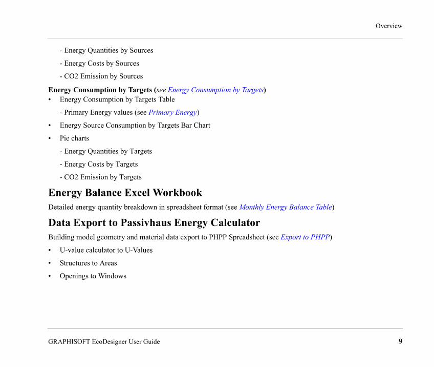
Energy Balance Excel Workbook Detailed energy quantity breakdown in spreadsheet format (see Monthly Energy Balance Table)
Data Export to Passivhaus Energy Calculator Building model geometry and material data export to PHPP Spreadsheet (see Export to PHPP)
• U-value calculator to U-Values
• Structures to Areas
• Openings to Windows
GRAPHISOFT EcoDesigner User Guide 9
Definitions
Function Enhancements in EcoDesigner for ArchiCAD 15Enhanced U-value OverrideMore accurate modeling in the preliminary design phase (see U-value Override)
• More detailed substitute material property options
Energy Source Options on the User Interface Easy application of local settings (see Energy Source Factors)
• Primary energy factors
• CO2 Emission factors
Report Header UpdateEnhanced documentation (see Report Header)
• Custom Evaluation Report Title
• Project Name Displayed
• Project File Name Displayed
DefinitionsAAbsorbance (also called absorption factor/attenuation coefficient): The physical process of absorbing light. This is a quantity that characterizes how easily a material or medium can be penetrated by a beam of light, sound, particles, or other energy or matter. A large attenuation coefficient means that the beam is quickly “attenuated” (weakened) as it passes through the medium, and a small attenuation coefficient means that the medium is relatively transparent to the beam. Attenuation coefficient is measured using units of reciprocal length. The terms “attenuation coefficient” and “absorption coefficient” are generally used interchangeably.
10 GRAPHISOFT EcoDesigner User Guide

Definitions
Note: “Attenuation coefficient.” Wikipedia the Free Encyclopedia. 14 May. 2010 < http://en.wikipedia.org/wiki/Attenuation_coefficient >Absorption factor: see Absorbance
Adiabatic wall: walls of the building shell that separate heated spaces. They are called adiabatic due to the absence of heat transfer through them. These walls do not contribute to heat losses but they do contribute to the thermal inertia (heat storage mass).
Air change per hour (also called air exchange rate) is the number of interior volume air changes that occur per hour, and has units of 1/h. An air change does not represent a complete change of all air in the enclosure or structure unless it can be considered “plug flow”. The actual percentage of an enclosure’s air, which is exchanged in a period depends on the airflow efficiency of the enclosure and the methods used to ventilate it. The actual amount of air changed in a well-mixed ventilation scenario will be 63.2% after 1 hour and 1 ACH. Examples: kitchens 20–60, Public bathrooms 6, Class rooms 3–4, Laboratories 6–12, Smoking rooms 10–15, Warehousing 1–2. See also: Ventilation
Note: “Air changes per hour.” Wikipedia the Free Encyclopedia. 14 May. 2010 < http://en.wikipedia.org/wiki/Air_changes_per_hour>Air exchange rate: see Air change per hour
Air leakage: see Infiltration
Air to air energy recovery: (a.k.a. heat recovery ventilation, HRV, mechanical ventilation heat recovery or MVHR) is an energy recovery ventilation system, using equipment known as a heat recovery ventilator, heat exchanger, air exchanger or air-to-air exchanger, that employs a counter-flow heat exchanger between the inbound and outbound air flow. Heat recovery ventilation provides fresh air and improved climate control, while also saving energy by reducing the heating (or cooling) requirements.
Attenuation coefficient: see Absorbance
BBuilding volume (net): the volume of the conditioned air space of a building measured by its internal dimensions.
GRAPHISOFT EcoDesigner User Guide 11

Definitions
CCarbon footprint: the carbon dioxide emissions caused by the operation of the building. The carbon footprint is a subset of the ecological footprint and of the more comprehensive Life Cycle Assessment (LCA). Once the size of a carbon footprint is known, a strategy can be devised to reduce it, e.g. by technological developments or consumption strategies. The mitigation of carbon footprints through the development of alternative projects, such as solar or wind energy, represents a way of reducing a carbon footprint and is often known as Carbon offsetting.
Note: “Carbon footprint.” Wikipedia the Free Encyclopedia. 14 May. 2010 < http://en.wikipedia.org/wiki/Carbon_footprint>Carbon offsetting: see Carbon footprint
Climate data: see Weather data
Cold bridge: see Thermal bridge
Conditioned area: is the sum of the floor areas of spaces that are heated or cooled.
DDirect Shade Factor Reduction: defines the percentage of heat energy that reaches the interior space due to solar irradiation.
District cooling: Working on broadly similar principles to district heating, district cooling delivers chilled water or other media to multiple buildings for cooling. The cooling (actually heat rejection) is usually provided from a dedicated cooling plant.
Note: “District cooling.” Wikipedia the Free Encyclopedia. 14 May. 2010 < http://en.wikipedia.org/wiki/District_cooling>
District heating (also called Teleheating): is a system for distributing heat generated in a centralized location for residential and commercial heating requirements such as space heating and water heating. The heat is often obtained from a cogeneration plant burning fossil fuels but increasingly biomass, although heat-only boiler stations, geothermal heating and central solar heating are also used, as well as nuclear power. District heating plants can provide higher efficiencies and better pollution control than localized boilers.
Note: “District heating.” Wikipedia the Free Encyclopedia. 14 May. 2010 <http://en.wikipedia.org/wiki/District_heating>
12 GRAPHISOFT EcoDesigner User Guide

Definitions
EEnergy evaluation: Information about the project’s energy performance based on building geometry analysis, weather data and some user input. As a result, yearly energy consumption, carbon footprint and monthly energy balance is available.
Energy fluctuation: irregular energy flow through a building structure (e.g. a wall)
FFenestration: products that fill openings in a building envelope, such as windows, doors, skylights, curtain walls, etc., that permit the passage of light.
Fluorescent light: is a gas-discharge lamp that uses electricity to excite mercury vapor. The excited mercury atoms produce short-wave ultraviolet light that then causes a phosphor to fluoresce, producing visible light. A fluorescent lamp converts electrical power into useful light more efficiently than an incandescent lamp. Lower energy cost typically offsets the higher initial cost of the lamp. The lamp is more costly because it requires a ballast to regulate the flow of current through the lamp.
Fresh air heating: Combined heating – air conditioning system, which gains the heat of the taken air, and heats up the fresh air in an air-handling unit, before being exhaled back out into the room. Cold and hot pipes, or more advanced technology is used to control the temperature of the air as it passes through the system. All of this is usually controlled from a basement or a control box somewhere secluded in the building.
GGreen energy: Green energy in EcoDesigner consists of energy obtained by air to air energy recovery, solar collectors and heat pumps. For further info, see these definitions.
HHeat capacity: see Heat storage mass
Heat pump: is a machine or device that moves heat from one location (the ‘source’) to another location (the ‘target’, ‘sink’ or ‘heat sink’) using mechanical work. Most heat pump technology moves heat from a low temperature heat source to a higher temperature heat sink. Most commonly, heat pumps draw heat from the air or from the ground. The reversing valve switches the direction of refrigerant through the cycle and therefore the heat pump may deliver either
GRAPHISOFT EcoDesigner User Guide 13
Definitions
heating or cooling to a building. In the cooler climates the default setting of the reversing valve is heating. The default setting in warmer climates is cooling.
Note: “Heat pump.” Wikipedia the Free Encyclopedia. 14 May. 2010 < http://en.wikipedia.org/wiki/Heat_pump>
Heat source: A heat source is anything that can heat up a building. Heat sources can be external (from outside the building) or internal (from inside the building). External heat sources include: the Sun, reflected sunlight, any kind of fuel, electricity and released heat from the ground. Internal heat sources can be electric equipment, people, lightning systems, etc.
Heat storage mass (also known thermal mass, thermal capacitance or heat capacity - Cth): is the capacity of a body to store heat. It is typically measured in units of J/°C or J/K (which are equivalent). If the body consists of a homogeneous material with sufficiently known physical properties, the thermal mass is simply the mass of material present times the specific heat capacity of that material. Thermal mass as a concept is most frequently applied in the field of building design. In this context, thermal mass provides “inertia” against temperature fluctuations, sometimes known as the thermal flywheel effect. For example, when outside temperatures are fluctuating throughout the day, a large thermal mass within the insulated portion of a house can serve to “flatten out” the daily temperature fluctuations, since the thermal mass will absorb heat when the surroundings are hotter than the mass, and give heat back when the surroundings are cooler. This is distinct from a material’s isolative value, which reduces a building’s thermal conductivity, allowing it to be heated or cooled relatively separate from the outside, or even just retain the occupants’ body heat longer.
Note: “Thermal mass.” Wikipedia the Free Encyclopedia. 14 May. 2010 < http://en.wikipedia.org/wiki/Thermal_mass>
Heat transfer coefficient: is used in calculating the heat transfer, typically by convection or phase change between two aggregates. The heat transfer coefficient has SI units in watts per meter squared-kelvin [h=W/m2K].
H=Q/AxΔTxΔt)
where
H = heat transfer coefficient, [W/m2K]
ΔQ = heat input or heat lost, [J]
14 GRAPHISOFT EcoDesigner User Guide

Definitions
A = heat transfer surface area, [m2 ]
ΔT = difference in temperature between the solid surface and surrounding fluid area, [K]
Δt = time period, [s]
Note: “Heat transfer coefficient.” Wikipedia the Free Encyclopedia. 14 May. 2010 < http://en.wikipedia.org/wiki/ Heat_transfer_coefficient >
Hot water generation: Typical domestic uses of hot water are for cooking, cleaning, bathing, and space heating. In industry, both hot water and water heated to steam have many uses. Appliances for providing a more-or-less constant supply of hot water are variously known as water heaters, boilers, heat exchangers, calorifiers, or geysers depending on whether they are heating potable or non-potable water, in domestic or industrial use, their energy source, and in which part of the world they are found. In domestic installations, potable water heated for uses other than space heating is sometimes known as domestic hot water (DHW). In many countries the most common energy sources for heating water are fossil fuels: natural gas, liquefied petroleum gas, oil, or sometimes solid fuels. These fuels may be consumed directly or by the use of electricity. Alternative energy such as solar energy, heat pumps, hot water heat recycling, and sometimes geothermal heating, may also be used as available, usually in combination with backup systems supplied by gas, oil or electricity. In some countries, district heating is a major source of water heating.
Note: “Water heating.” Wikipedia the Free Encyclopedia. 14 May. 2010 < http://en.wikipedia.org/wiki/ Water_heating >
Human heat gain: the amount of heat produced by the human bodies in the building.
IIncandescent light: is a source of electric light that works by incandescence (a general term for heat-driven light emissions, which includes the simple case of black body radiation). An electric current passes through a thin filament, heating it to a temperature that produces light. The enclosing glass bulb contains either a vacuum or an inert gas to prevent oxidation of the hot filament. Incandescent bulbs are also sometimes called electric lamps, a term also applied to the original arc lamps.
Note: “Incandescent light bulb.” Wikipedia the Free Encyclopedia. 14 May. 2010 <http://en.wikipedia.org/wiki/ Incandescent_light_bulb>
GRAPHISOFT EcoDesigner User Guide 15
Definitions
Infiltration (air leakage/air permeability): is the unintentional or accidental introduction of outside air into a building, typically through cracks in the building envelope and through use of doors for passage. Infiltration is caused by wind, building pressurization and stack effect. The infiltration rate is the volumetric flow rate of outside air into a building, typically in cubic feet per minute (CFMs) or liters per second (LPSs).
Note: “Infiltration (HVAC).” Wikipedia the Free Encyclopedia. 14 May. 2010 < http://en.wikipedia.org/wiki/ Infiltration_(HVAC)>
Internal heat gain: may result from the heat output of human bodies, lamps motors and appliances. In buildings such as office buildings, commercial stores, shopping centers, entertainment halls etc. much of the overheating problem during the summer can be caused by heat produced by equipment or by a high level of artificial lighting.
Internal target temperature: the temperature (range) needed in a room or building when it is used. Based on the activities in the building, the profile may vary by workdays/non-working days, needed temperature and daily period.
LLED light: A light-emitting-diode lamp is a solid-state lamp that uses light-emitting diodes (LEDs) as the source of light. Since the light output of individual light-emitting diodes is small compared to incandescent and compact fluorescent lamps, multiple diodes are used together. LED lamps can be made interchangeable with other types. Most LED lamps must also include internal circuits to operate from standard AC voltage. LED lamps offer long life and high efficiency, but initial costs are higher than those of fluorescent lamps.
Note: “LED lamp.” Wikipedia the Free Encyclopedia. 14 May. 2010 < http://en.wikipedia.org/wiki/ LED_lamp>
Lighting power density (LPD): the maximum lighting power per unit area of a building classification of space function. Examples for a whole building in W/ft2: Convention Center 1.22, Hospital 1.23, Hotel 1.02, Museum 1.11, Parking garage 0.27, School/University 1.2, Transportation 1.0, Warehouse 0.82.
Linear thermal currents: According to the second law of thermodynamics (a.k.a. the Clausius statement), thermal currents are induced inside a (building) material, if there is a temperature difference between its two sides. Theories of fundamental thermal physics are only valid if these thermal currents are perpendicular to the surface (one dimensional). This, in reality, could occur only if the structures were infinitely large and the composite layers were homogenous and parallel to each-other. Still, general external building shell elements are evaluated supposing that the nature of heat flow
16 GRAPHISOFT EcoDesigner User Guide

Definitions
through them is linear, because the result obtained using this method is within the error margin, compared to actual measurements. For further info on thermal currents, see also: Multi-dimensional thermal currents and Transmission.
MMechanical cooling: Air refrigeration is provided through the removal of heat. The definition of cold is the absence of heat; all mechanical air cooling systems work on this basic principle. Heat can be removed through the process of radiation, convection, and heat cooling through a process called the refrigeration cycle. The conduction mediums, such as water, air, ice, and chemicals, are referred to as refrigerants.
Note: “HVAC.” Wikipedia the Free Encyclopedia. 14 May. 2010 < http://en.wikipedia.org/wiki/ HVAC>
Mechanical ventilation (a.k.a. forced ventilation): through an air handling unit or direct injection to a space by a fan. A local exhaust fan can enhance infiltration or natural ventilation, thus increasing the ventilation air flow rate. See also Natural ventilation and Infiltration.
Note: “Ventilation (architecture).” Wikipedia the Free Encyclopedia. 14 May. 2010 < http://en.wikipedia.org/wiki/Ventilation_(architecture)>
Monthly energy balance: according to the Conservation of Energy law of physics, when monitoring all energy flows related to the building, the amount of energy the building emits must equal the amount of energy supplied to the building. The Monthly Energy Balance bar chart on EcoDesigner’s Energy Balance Evaluation report is the graphical representation of these energy flows.
Multi-dimensional thermal currents: According to the second law of thermodynamics (a.k.a. the Clausius statement), thermal currents are induced inside a (building) material, if there is a temperature difference between its two sides. In reality, multi-dimensional thermal currents occur at places of:
• material change
• change in geometry
• change in construction
For further info on thermal currents, see also: Linear thermal currents and Transmission.
GRAPHISOFT EcoDesigner User Guide 17

Definitions
NNatural heating: this Heating type option in EcoDesigner has been developed for warm climate countries, where the annual energy required for heating is very low. The installation of a heating system is not necessary, if the fact that the internal air temperature drops below the prescribed level on a couple of chilly nights or mornings a year is tolerated by the inhabitants. Set Heating type to natural in such cases, for the calculation engine of EcoDesigner to assume that the external air is sufficient for heating purposes.
Natural heat source: see Natural heating
Natural ventilation: is the process of supplying and removing air through an indoor space by natural means. There are two types of natural ventilation in buildings: wind driven ventilation and stack ventilation. The pressures generated by ‘the stack effect’, also known as buoyancy, are quite low (typical values: 0.3 Pa to 3 Pa) while wind pressures are usually far greater (~1 Pa to 35 Pa). The majority of buildings employing natural ventilation rely primarily on wind driven ventilation, but stack ventilation has several benefits. The most efficient design for a natural ventilation building should implement both types of ventilation.
Note: ”Natural ventilation.” Wikipedia the Free Encyclopedia. 14 May. 2010 < http://en.wikipedia.org/wiki/ Natural_ventilation >
O
PPellet (wood): is a type of wood fuel, generally made from compacted sawdust. Pellets are usually produced as a by-product of sawmills and other wood-related industry. The pellets are extremely dense and can be produced with a low humidity content (below 10%) that allows them to be burned with very high combustion efficiency.
Note: “Wood pellet.” Wikipedia the Free Encyclopedia. 14 May. 2010 < http://en.wikipedia.org/wiki/ Wood_pellet >
Primary heat source: In EcoDesigner, primary heat sources include natural gas, propane, oil, wood, coal or Pellet. See also Secondary heat source.
Primary hot water source: In EcoDesigner, primary hot water sources include natural gas, propane, oil, wood, coal or Pellet. See also Secondary heat source.
18 GRAPHISOFT EcoDesigner User Guide

Definitions
RR-value (Thermal resistance coefficient): The inverse of the U value. A measure of thermal resistance used in the building and construction industry. Under uniform conditions it is the ratio of the temperature difference across an insulator and the heat flux. The bigger the number, the better the building insulation’s effectiveness. Typically it is measured in square-metre kelvins per watt or m²·K/W (or equivalently to m²·°C/W). A thermal barrier that is composed of several layers will have several thermal resistors in the analogous circuit, each in series. Increasing the thickness of an insulating layer increases the thermal resistance.
Note: “R-value (insulation).” Wikipedia the Free Encyclopedia. 14 May. 2010 < http://en.wikipedia.org/wiki/R-value_(insulation)>
SSecondary heat source: Energy produced from a primary heat source by a power plant, then fed to the building. In EcoDesigner, secondary heat sources include electricity, district cooling and district heating. See also Primary heat source, District cooling and District heating.
Solar collector (solar thermal collector panels): a collector designed to collect heat by absorbing sunlight. A collector is a device for converting the energy in solar radiation into a more usable or storable form. The energy in sunlight is in the form of electromagnetic radiation from the infrared (long) to the ultraviolet (short) wavelengths. The solar energy striking the earth’s surface depends on weather conditions, as well as location and orientation of the surface, but overall, it averages about 1,000 watts per square meter under clear skies with the surface directly perpendicular to the sun’s rays.
Note: “Solar thermal collector.” Wikipedia the Free Encyclopedia. 14 May. 2010 < http://en.wikipedia.org/wiki/ Solar_thermal_collector >
Solar gain (a.k.a. solar heat gain or passive solar gain) refers to the increase in temperature in a space, object or structure that results from solar radiation. The amount of solar gain increases with the strength of the sun, and with the ability of any intervening material to transmit or resist the radiation. Objects struck by sunlight absorb the short-wave radiation from the light and reradiate the heat at longer infrared wavelengths. Where there is a material or substance (such as glass) between the sun and the objects struck that is more transparent to the shorter wavelengths than the longer, then when the sun is shining the net result is an increase in temperature - solar gain.
Note: “Solar gain.” Wikipedia the Free Encyclopedia. 14 May. 2010 < http://en.wikipedia.org/wiki/ Solar_gain >
GRAPHISOFT EcoDesigner User Guide 19

Definitions
Solar irradiation decreasing constants: Shadows cast upon the building shell by external objects (Façade Shadings/Shading) are taken into consideration in EcoDesigner by applying numeric reduction percentage values, which may be set for each orientation individually.
Solar transmission: The percentage of incident solar radiation transmitted by an object which includes the direct Solar Transmission plus the part of the Solar Absorption reradiated inward. TST (Total Solar Transmission) divided by 100 equals Solar Heat Gain Coefficient (SHGC) or g-value.
Space heating: is a kind of heating using a self-contained device for heating an enclosed area. It is also known as a portable heater, a room heater or an auxiliary heater. Space heating generally warms a small space, and is usually held in contrast with central heating, which warms many connected spaces at once. Space heating does not include water heating, unless it is used for hydronic heating.
Note: “Space heater.” Wikipedia the Free Encyclopedia. 14 May. 2010 < http://en.wikipedia.org/wiki/ Space_heater >
TTeleheating: see District heating
Thermal bridge (also called cold bridge): is created when materials that are poor insulators come in contact, allowing heat to flow through the path created. Insulation around a bridge is of little help in preventing heat loss or gain due to thermal bridging; the bridging has to be eliminated, rebuilt with a reduced cross-section or with materials that have better insulating properties, or with an additional insulating component (a thermal break). Thermal bridges are characterized by multi-dimensional heat flows that are typically approximated by one-dimensional models of calculation, which are used in norms and standards for the thermal performance of buildings.
Note: “Thermal bridge.” Wikipedia the Free Encyclopedia. 14 May. 2010 < http://en.wikipedia.org/wiki/ Thermal_bridge >
Thermal conductivity (k): is the property of a material that indicates its ability to conduct heat. Thermal conductivity is measured in watts per kelvin metre [W/K, m]. Multiplied by a temperature difference (in kelvins, K) and an area (in square metres, m2), and divided by a thickness (in metres, m) the thermal conductivity predicts the power loss (in watts, W) through a piece of material.
20 GRAPHISOFT EcoDesigner User Guide

Definitions
Note: “Thermal conductivity.” Wikipedia the Free Encyclopedia. 14 May. 2010 < http://en.wikipedia.org/wiki/ Thermal_conductivity >Thermal mass: see Heat storage mass
Thermal resistance coefficient: see R-value
Total shade factor reduction: defines the percentage of total heat energy that reaches the interior space.
Total solar transmission: see Solar transmission.
Transmission (Heat transfer) is the transition of thermal energy from a hotter mass to a cooler mass. When an object is at a different temperature than its surroundings or another object, transfer of thermal energy, also known as heat flow or heat exchange, occurs in such a way that the body and the surroundings reach thermal equilibrium; this means that they are at the same temperature. Heat transfer always occurs from a higher-temperature object to a cooler-temperature one as described by the second law of thermodynamics (a.k.a. the Clausius statement). Where there is a temperature difference between objects in proximity, heat transfer between them can never be stopped; it can only be slowed. In case of building physics, thermal currents are induced inside a (building) material, if there is temperature difference between its two sides. See also: Linear thermal currents and Multi-dimensional thermal currents
Note: “Heat transfer.” Wikipedia the Free Encyclopedia. 14 May. 2010 < http://en.wikipedia.org/wiki/ Heat_transfer >
UU-value: the measure of the rate of heat loss through a material. Thus in all aspects of home design one should strive for the lowest U-values possible because, the lower the U-value, the less heat that is needlessly escaping. It is measured as the amount of heat lost through a one square meter of the material for every degree difference in temperature either side of the material. It is indicated in units of Watts per Meter Squared per Degree Kelvin or W/m2K. U-value is the inverse of the R-value.
VVentilation: the intentional movement of air from outside a building to the inside. It is the V in HVAC. Types of Ventilation are Mechanical forced ventilation, Natural ventilation and Infiltration.
See also: Air changes per hour
GRAPHISOFT EcoDesigner User Guide 21

Getting Started With EcoDesigner
WWeather data (or climate data): searchable records of climatology and historical weather for all locations, worldwide. The weather data used by EcoDesigner contains hourly records of air temperature, relative humidity, wind speed and solar radiance for a reference year.
Wind velocity: The horizontal direction and speed of air motion. It is a scalar quantity, the magnitude of the vector of motion.
Note: “Wind speed.” Wikipedia the Free Encyclopedia. 14 May. 2010 < http://en.wikipedia.org/wiki/ Wind_speed >
YYearly energy consumption: The annual amount of energy the project needs in order to fulfill the interior climate criteria specified for the function of the building.
Getting Started With EcoDesignerHardware/Software RequirementsThe hardware/software requirements for GRAPHISOFT EcoDesigner are identical to those of ArchiCAD 15. For more details, see “Getting Started with ArchiCAD 15” available from the ArchiCAD Help menu.
File CompatibilityEcoDesigner is an add-on that runs with ArchiCAD 15.
LicensesTo run GRAPHISOFT EcoDesigner with your commercially licensed copy of ArchiCAD 15, you need a separate license for EcoDesigner. This license can be located either on the same or a different dongle than the one with the ArchiCAD license. If you do not have a license for EcoDesigner, consult your ArchiCAD distributor.
If you have successfully installed EcoDesigner and begun work, but your EcoDesigner license is later missing for any reason while you are working with EcoDesigner, a Warning informs you that you have two choices:
22 GRAPHISOFT EcoDesigner User Guide

Getting Started With EcoDesigner
1) Restore the missing license, then continue working; or
2) Continue working in ArchiCAD, without EcoDesigner functionality.
Installation• Insert the GRAPHISOFT EcoDesigner CD into your computer’s DVD drive.
• On PC: Click on Install EcoDesigner in the menu to start the Installation Wizard.
If the start-up menu does not appear automatically on PC, double-click on the “Setup” application in the CD root directory.
• On MacOS: The “GRAPHISOFT EcoDesigner for ArchiCAD 15” volume will be mounted on your desktop. Open this volume and click the “EcoDesigner Installer” icon to start the Installation Wizard.
Program Folder LocationAfter you accept the license agreement, the program will locate the ArchiCAD folder on your computer’s hard drive to which EcoDesigner will be installed. (This must be the folder of an installed ArchiCAD that is compatible with EcoDesigner.)
UninstallTo uninstall EcoDesigner from a PC, it is best to use the “Add or Remove Programs” utility, accessible from the Control Panel.
Alternatively, navigate to the “Uninstall EcoDesigner” folder in your ArchiCAD folder, and select the “Uninstaller” application.
On MacOS, navigate to the “Uninstall EcoDesigner” folder in your ArchiCAD folder, and select the “Uninstaller” application.
Calculation Unit SettingsEcoDesigner uses the calculation units defined by you in ArchiCAD, at Options > Project Preferences > Calculation Units & Rules. Thus, EcoDesigner uses the same units as the ArchiCAD Project to which it is applied.
GRAPHISOFT EcoDesigner User Guide 23
Getting Started With EcoDesigner
An additional unit setting option is available at the Hot water generation section of the MEP Systems and Energy tab page (see Hot Water Generation): choose either Celsius or Fahrenheit for the water temperature. This way you can set the temperature scale independently of other units. (This can be useful, for example, if your country uses metric dimensions and Fahrenheit temperatures concurrently.)
Localized EcoDesigner Contents – the XML FilesEcoDesigner creates its own folder in the Add-Ons folder of ArchiCAD 15 when installed (C:\Program Files\Graphisoft\ArchiCAD 15\Add-Ons\EcoDesigner). The version-specific localized content folder or folders (named with three-character nationality codes) are located here. EcoDesigner automatically loads its data from the folder corresponding to the localized version of ArchiCAD under which it runs. Each localized content folder contains the following six .xml files:
• DefaultFillAssignments.xml (see Default Thermal Property Assignments)
• DefaultValues.xml
See the following sections for details on XML files: Custom Façade Shadings, Customizing the Building Volume Display, Surface, Infiltration and Customizing the Appearance of the Energy Balance Evaluation Sheet.• InternalUsages.xml (see Activity and Custom Activity Profiles)
• MaterialCatalog.xml (see U-value Override)
• OpeningCatalog.xml (see Openings)
• ShadingCatalog.xml (see Shading Devices)
• PHPP Mapping (see Export to PHPP)
• DefaultEnergySourceProperties.xml (see Energy Source Factors)
To minimize the numeric user input required, several input parameters are set within EcoDesigner by default or are listed in database catalogs. The .xml files shown above contain these default settings and catalogs. It is possible for users to modify the content of these files by simply text-editing them, in order to tailor the application to their preferences and needs. The best software to use for this purpose is TextPad (available free for download from the internet). Microsoft Word is not suitable for editing .xml file content, as it changes the file format when the modified version is saved. NotePad may be used; however it is inconvenient as it displays the files in one continuous line.
24 GRAPHISOFT EcoDesigner User Guide

Getting Started With EcoDesigner
It is strongly advised to save a copy of the original .xml files to a different folder prior to modifying them. Replacing the modified .xml’s with the originals allow the users to reset the changed settings and return to EcoDesigner’s default state. Users should also back up their own modified files before installing any hotfixes or upgrades to ArchiCAD or EcoDesigner, as the update process may replace customized .xml files. ArchiCAD must be closed and then restarted in order for the modifications to take effect.
Folders Used by EcoDesignerEcoDesigner manages data using three different folders:
• \Add-Ons\EcoDesigner: (see Localized EcoDesigner Contents – the XML Files)
The locations of the other two folders (Temporary and Cache Folder) are specified individually under Options > Work Environment > Special Folders for every user.
• Temporary Folder: When ArchCAD is launched, an EcoDesigner reference result file (.vdt format) is copied into this folder automatically. If an evaluation is carried out in EcoDesigner during the work session, a resultant temporary .vut file (VIP Energy file format that may be opened by the StruSoft VIP-Energy software for detailed analysis) is saved here, as well. Both the .vdt and the .vut files are needed by EcoDesigner to produce the Energy Evaluation Report, because the result file alone is meaningless without the reference data. (For more info on the .vdt and .vut files, see Localized EcoDesigner Contents – the XML Files)
The Temporary folder is also used to store the calculation error file (.err file format), which contains information about the cause of failure in case of unsuccessful evaluation.
The climate .xml file currently in use is also copied here from the Cache Folder.
• Cache Folder: Climate files coming from the EcoDesigner folder or from the online weather database are managed here.
GRAPHISOFT EcoDesigner User Guide 25

Working with EcoDesigner
Working with EcoDesignerTo be able to perform a successful evaluation with EcoDesigner, you must create the virtual building model in ArchiCAD. The more detailed the model, the more accurate the calculation results will be. For successful evaluation, you should model, at minimum, the enveloping building structures and the major internal structures that represent significant heat storage mass.
For best results with EcoDesigner, follow these modeling conventions:
• Use walls, slabs, roofs and Curtain Walls to model your building structures. (For example, do not use a mesh tool to model your roof or the complex walls element type, as these are not supported by EcoDesigner.)
• Each structure should be either an interior or exterior structure. For example, if you have a slab that is both, split it into separate interior and exterior slabs.
• If possible, do not use multiple separate parallel walls (or slabs or roofs) to model composite structures. If such constructions exist in the building model, make sure that only one of the parallel structures is marked up as part of the building shell.
• Use fills consistently within your project: a particular fill should always indicate the same single building material or composite.
• When modeling wall intersections for several design variations, make sure you use the layer intersections groups consistently in each design variation.
If energy balance evaluation is needed only on a certain part of the model, select that part using the marquee tool. In this case, only the structures within the marquee boundaries will be analyzed.
26 GRAPHISOFT EcoDesigner User Guide
Working with EcoDesigner
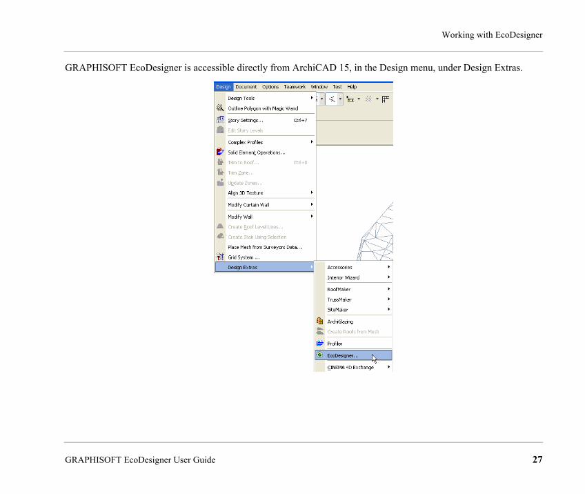
GRAPHISOFT EcoDesigner is accessible directly from ArchiCAD 15, in the Design menu, under Design Extras.
GRAPHISOFT EcoDesigner User Guide 27

Working with EcoDesigner
Automatic Model AnalysisAutomatic Model Analysis occurs when you run EcoDesigner (Design > Design Extras > EcoDesigner) on a project for the first time. Automatic Model Analysis investigates the visible elements of the model and defines which belong to the shell of the building and which make up the interior structures group.
The analysis further categorizes the structures that make up the building shell according to their relevance in the building’s energy system:
• Roofs and Shell Slabs
• External Walls
• Floors On Ground
• Basement Walls
• Basement Floors
• Interior Structures
When Automatic Model Analysis is complete, these automatically generated selection groups are marked up and displayed in different colors on the Floor Plan and in 3D. Their geometry data is gathered and saved on the Building Shell Elements list and the Openings list. (See Structures and Openings.)
28 GRAPHISOFT EcoDesigner User Guide

Working with EcoDesigner
The “Model analysis done” dialog box appears, showing the number of Building shell elements and Interior structure elements found.
This Model Analysis is a quick, automatic process. You should review and, if needed, modify any of the element categorizations using the Model Review Palette. (See Model Review.)
From the “Model Analysis Done” dialog box, click “OK” to enter the EcoDesigner Dialog Box.
GRAPHISOFT EcoDesigner User Guide 29

Working with EcoDesigner
Model ReviewUse the Model Review palette to modify the selection sets generated by Automatic Model Analysis.
This palette is available by clicking the Model Review button from the Structures tab page of the EcoDesigner dialog box.
The Model Review palette lists the building structure groups analyzed during Automatic Model Analysis:
• Building Shell Elements above ground level (Roofs and Shell Slabs, External Walls)
• Structures in Contact with Ground (Floors on Ground, Basement Walls, Basement Floors)
• Interior Structures
On the Model Review palette, click the eye icons open or shut to display or hide the elements belonging to each group.
Element groups in each of these broad categories are displayed on screen in the colors indicated on the Palette. (To change the color of any of these categories, see Changing Mark-Up colors).
30 GRAPHISOFT EcoDesigner User Guide

Working with EcoDesigner
Changing Mark-Up ColorsThe Model Review palette is based upon ArchiCAD’s Mark-Up Palette, using some of the applicable Mark-Up functions in simplified form for EcoDesigner. Therefore, some settings of the Options > Element attributes > Mark-Up Styles dialog box affect the appearance of the Model Review.
It is possible to alter the pen colors ArchiCAD uses to highlight the structure groups by changing the pens defined under Style Attributes in the Mark-Up Styles dialog box.
Important: To visualize the Model Review mark-ups, the Show Mark-Up Items checkbox must be checked in the Document > Set Model View > Model View Options dialog box.
GRAPHISOFT EcoDesigner User Guide 31

Working with EcoDesigner
Modify Element’s Building Structure GroupUse the “Highlight Element” and “Remove Highlight” buttons to manually change the building structure group of any project element highlighted in the program.
For example, you can remove a wall from the External Wall group and put it into the Basement Walls group instead. To do this:
1) Highlight the wall.
2) Click the “Remove Highlight from Selected Elements” button below the Building structure types list.
3) Then click on the group you need (Basement Walls, in our case).
4) Click “Highlight Selected Elements”.
The selected wall is now categorized as a Basement Wall.
Adiabatic Walls of the Building ShellAdiabatic walls are walls of the building shell that separate heated spaces. They are called adiabatic due to the absence of heat transfer through them. Such walls (e.g. fire walls separating row-houses or other adjacent buildings) should be marked up as internal structures in order to get an accurate energy evaluation result.
32 GRAPHISOFT EcoDesigner User Guide

Working with EcoDesigner
Shell SlabsA common structural situation in architecture is the case of thermal insulated slabs separating heated and unheated spaces (e.g. floor slab below unheated attics; slabs above arcades, external spaces or unheated basements). These structures are called Shell Slabs in EcoDesigner for ArchiCAD 15. Mark up such slabs as Roofs and Shell Slabs (orientation: upward) and set their surfaces to reflective using the Surface button next to the relevant entry of the Building shell elements list on the Structures tab page (see Building Shell Elements).
Select Elements Click the “Select Elements” button to select all elements of the currently highlighted group.
GRAPHISOFT EcoDesigner User Guide 33

Working with EcoDesigner
Show/Hide Building VolumeThe “Show/Hide building volume” button toggles the visibility of the 3D Building Volume.
The 3D Building Volume is the graphical representation of the conditioned building volume calculated by Automatic Model Analysis. While the Automatic Model Analysis subtracts the volume of the walls, slabs, columns and beams from the total building volume, these subtractions are not reflected in the display of the 3D Building volume by default.
It is possible to change this default display setting (See Customizing the Building Volume Display).
Note: The automatic heated building volume algorithm produces accurate results only if the virtual building model is constructed properly in ArchiCAD. Inaccurate element connections may produce open floor area polygons and, as a result, incorrect volumes may be generated by EcoDesigner. In this case, you should either fix the incorrect element connections of the ArchiCAD model or modify the value of the Building volume via numerical input on the Structures tab page of the EcoDesigner dialog box. (See Building Geometry.)
34 GRAPHISOFT EcoDesigner User Guide

Working with EcoDesigner
Customizing the Building Volume DisplayEcoDesigner is capable of displaying the actual model the volume calculation is based on.
If the values are changed from 0 to 1 in the following lines of the DefaultValues.xml file (See Localized EcoDesigner Contents – the XML Files), turning on the originally disabled functions, the subtraction of the respective structure types becomes visible on the 3D Building Volume.
<DefaultValue Name="EcoDesignerData.CreateExtZones.TrimRoofs" Value="1" />
<DefaultValue Name="EcoDesignerData.CreateExtZones.TrimSlabs" Value="1" />
<DefaultValue Name="EcoDesignerData.CreateExtZones.SubstractBeams" Value="0" />
<DefaultValue Name="EcoDesignerData.CreateExtZones.SubstractColumns" Value="0" />
<DefaultValue Name="EcoDesignerData.CreateExtZones.SubstractSlabs" Value="0" />
<DefaultValue Name="EcoDesignerData.CreateExtZones.SubstractWalls" Value="0" />
The lines of the DefaultValues.xml that set the 3D building volume display
Reanalyze ModelClick this button to run the Automatic Model Analysis again. This function overrides all stored EcoDesigner geometric information within the project, so any building structure groups that you modified manually will be overridden by automatically generated ones.
GRAPHISOFT EcoDesigner User Guide 35
Working with EcoDesigner
Back to EcoDesignerClick “Back to EcoDesigner” to approve the marked selection sets as reflected in the Model Review palette. The program then updates the geometric data (surface area, orientation, volume, perimeter, etc.) necessary for energy evaluation of the marked structures.
If you exit and later reenter EcoDesigner within a given project, this geometric data will remain available until you select the “Re-analyze model” function.
Additional User InputUse the EcoDesigner Dialog Box, consisting of five tab pages, to provide further input required by the EcoDesigner calculation engine. This dialog box is resizable, in order to fit any screen conveniently, by clicking on and dragging its bottom right corner.
If you are working on a shared Teamwork project, you must first reserve the EcoDesigner dialog box (using the control light interface on any of its tab pages) to be able to access these controls.
36 GRAPHISOFT EcoDesigner User Guide

Working with EcoDesigner
Location and Function
GRAPHISOFT EcoDesigner User Guide 37

Working with EcoDesigner
Report HeaderClick the blue Information icon below Project Location to access the ArchiCAD Project Info dialog box. Project Info line 15 is entitled EcoDesigner report header text. Text entered here appears on the header of the Building Energy Evaluation report sheet; below the content of line 2 entitled Project Name.
Project LocationProject location is defined by geographical coordinates and a custom name. Click Set City to access a predefined list of locations from the Cities attribute of ArchiCAD 15.
If your city is listed here, EcoDesigner has access to all the relevant weather data needed to perform the energy analysis; in this case, there is no need to download weather information from the Internet.
If the location of your building is not listed here, enter the city name and its coordinates (Latitude, Longitude and Time zone), then click Add to add it to the Cities list.
Click OK in the Cities dialog box to activate an Internet connection to the Online Weather Database server; EcoDesigner obtains the relevant weather data (air temperature, relative humidity, wind speed and solar radiance) of the specified location.
Note: Climate data is obtained from the Strusoft climate website, at http://climate.vipenergy.se.
All climate data are created from NCEP Reanalysis data provided by the NOAA-CIRES Climate Diagnostics Center, Boulder, Colorado, USA, from their website at http://www.cdc.noaa.gov/.
38 GRAPHISOFT EcoDesigner User Guide

Working with EcoDesigner
Once the weather data of a custom location are downloaded for a certain project, they are stored in the ArchiCAD Cache Library, so the data remain available when opening another ArchiCAD project later, even if the computer is not online.
Project North may be set by clicking “Set Project North,” which takes you to the “Levels and Project North” page of ArchiCAD’s Project Preferences.
Climate FilesIf the building site is in one of the cities shown in the Set City list, it means that the necessary weather data are available within the default climate data file in the EcoDesigner folder. (AddOns \ EcoDesigner \ WeatherDataCache.zip). The user may unzip this data file to access the package of text files in .vipclimate file format. Each text file starts with some general information concerning the monitored location and contains the hourly values of relevant weather information listed below, in a table-like format:
VIP-Climate file rev 3.0Lock ID :12345Company name :GRAPHISOFT EcoDesignDescription :Nottingham
Descriptionid :Nottingham-2007Year :2007Latitude :52.90Longitude :357.50No LeapyearHour of year = HoYDay of year = DoYDateHour of day = HoD
GRAPHISOFT EcoDesigner User Guide 39
Working with EcoDesigner
Temperature = T oCRel humidity = RH %Windspeed = WS m/s
Solar radiation = SR W/m2General information paragraph of example climate file
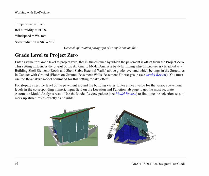
Grade Level to Project ZeroEnter a value for Grade level to project zero, that is, the distance by which the pavement is offset from the Project Zero. This setting influences the output of the Automatic Model Analysis by determining which structure is classified as a Building Shell Element (Roofs and Shell Slabs, External Walls) above grade level and which belongs in the Structures in Contact with Ground (Floors on Ground, Basement Walls, Basement Floors) group (see Model Review). You must use the Re-analyze model command for this setting to take effect.
For sloping sites, the level of the pavement around the building varies. Enter a mean value for the various pavement levels in the corresponding numeric input field on the Location and Function tab page to get the most accurate Automatic Model Analysis result. Use the Model Review palette (see Model Review) to fine-tune the selection sets, to mark up structures as exactly as possible.
40 GRAPHISOFT EcoDesigner User Guide

Working with EcoDesigner
Obviously, the more detailed the model, the more accurate selections can be made. If external walls are modeled using separate ArchiCAD wall elements for segments under and above the ground, for example, as with execution drawings, then they can be marked more accurately than on the draft model.
Wind ProtectionChoose the Wind Protection option that best describes your building’s wind exposure: Protected, Partly Protected or Unprotected.
SurroundingsChoose the Surroundings option that best describes the environment of your building: Waterfront, Garden or Paved.
This setting determines the level of indirect radiation that bounces back from these surfaces and reaches the building shell.
Facade ShadingsEcoDesigner for ArchiCAD 15 does not automatically determine the extent to which shadows are cast on each elevation of the building. Use the Facade Shadings button to activate a separate dialog with a list of those sides of the building that receive the sunlight (the list of Orientations can vary depending on project location).
For each orientation, choose the options that best describe the amount of shading resulting from:
• External objects (choose an option - Not shaded, Slightly shaded, Shaded or Very shaded - from the Shading column)
• Vertical shadow-casting edges (choose an option - Plain, Average or Complex - from the Complexity column)
• Horizontal shadow-casting edges (choose an option - None, Small or Large - from the Roof Canopy column)
GRAPHISOFT EcoDesigner User Guide 41
Working with EcoDesigner
The more complex the building elevation, the more the building is self-shaded, and the less it is affected by direct sunlight.
It is possible to edit multiple entries of the Façade Shadings list: select an entry that needs to be modified, and then add further entries to the selection by moving the pointer with the mouse without releasing the left mouse button, or by clicking on the entries while pressing the CTRL or the SHIFT key. Finally, use the function buttons that appear by the first selected line to define Façade shading properties for the selected orientations.
Depending on your choice, the icons at the top of each list (Shading/Complexity/Roof Canopy) change in appearance to help you make the right selections.
Custom Façade ShadingsShadows cast upon the building shell by external objects (Façade Shadings/Shading) are taken into consideration by applying solar irradiation decreasing constants, which may be set for each orientation individually. Default numeric reduction percentage values linked to different levels of external shading are stored in the DefaultValues.xml file (see Localized EcoDesigner Contents – the XML Files).
<DefaultValue Name="ProjectData.FacadeShading.Shading.NotShaded" Value="5" /><DefaultValue Name="ProjectData.FacadeShading.Shading.SlightlyShaded" Value="10" /><DefaultValue Name="ProjectData.FacadeShading.Shading.Shaded" Value="15" /><DefaultValue Name="ProjectData.FacadeShading.Shading.VeryShaded" Value="30" />
Solar irradiation reduction percentage default values
The effect of shadows cast by projecting parts of the building shell on itself may be set by applying one of the predefined complexity profiles in the Façade Shadings dialog. Data describing the different levels of elevation complexity are stored in the ShadingCatalog.xml (see Localized EcoDesigner Contents – the XML Files). Horizontal edge angles (Façade Shadings/Roof Canopy) and vertical fin side angles (Façade Shadings/Complexity) are used in pairs to define horizontal and vertical lines as the borders of the shadow masks on elevations facing each orientation separately.
42 GRAPHISOFT EcoDesigner User Guide
Working with EcoDesigner
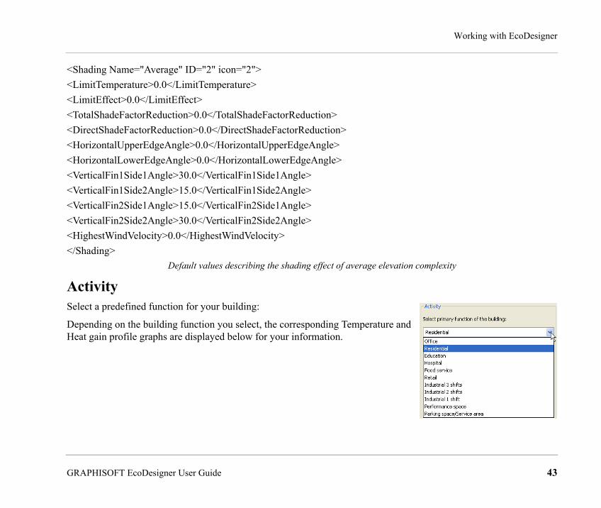
<Shading Name="Average" ID="2" icon="2"><LimitTemperature>0.0</LimitTemperature><LimitEffect>0.0</LimitEffect><TotalShadeFactorReduction>0.0</TotalShadeFactorReduction><DirectShadeFactorReduction>0.0</DirectShadeFactorReduction><HorizontalUpperEdgeAngle>0.0</HorizontalUpperEdgeAngle><HorizontalLowerEdgeAngle>0.0</HorizontalLowerEdgeAngle><VerticalFin1Side1Angle>30.0</VerticalFin1Side1Angle><VerticalFin1Side2Angle>15.0</VerticalFin1Side2Angle><VerticalFin2Side1Angle>15.0</VerticalFin2Side1Angle><VerticalFin2Side2Angle>30.0</VerticalFin2Side2Angle><HighestWindVelocity>0.0</HighestWindVelocity></Shading>
Default values describing the shading effect of average elevation complexity
ActivitySelect a predefined function for your building:
Depending on the building function you select, the corresponding Temperature and Heat gain profile graphs are displayed below for your information.
GRAPHISOFT EcoDesigner User Guide 43
Working with EcoDesigner
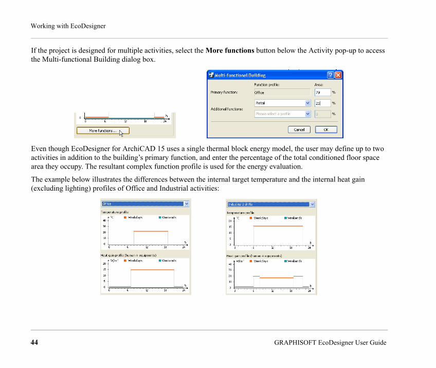
If the project is designed for multiple activities, select the More functions button below the Activity pop-up to access the Multi-functional Building dialog box.
Even though EcoDesigner for ArchiCAD 15 uses a single thermal block energy model, the user may define up to two activities in addition to the building’s primary function, and enter the percentage of the total conditioned floor space area they occupy. The resultant complex function profile is used for the energy evaluation.
The example below illustrates the differences between the internal target temperature and the internal heat gain (excluding lighting) profiles of Office and Industrial activities:
44 GRAPHISOFT EcoDesigner User Guide

Working with EcoDesigner
Custom Activity ProfilesIt is possible for users to define and save custom Temperature and Heat gain profiles in addition to the ones offered in the standard EcoDesigner package. This may become necessary if the function of a certain project is not among the default building activity profiles. Data describing building functions are located in the InternalUsages.xml file (see Localized EcoDesigner Contents – the XML Files).
<InternalUsage Name="Office">
<HotW>0.000009</HotW>
<HotWLgh>0</HotWLgh>
<TemperatureProfile>
<Min>18</Min>
<Max>25</Max>
<WorkDay>0 0 0 0 0 0 0 0 22 22 22 22 22 22 22 22 22 22 22 0 0 0 0 0</WorkDay>
<FreeDay>0 0 0 0 0 0 0 0 0 0 0 0 0 0 0 0 0 0 0 0 0 0 0 0</FreeDay>
</TemperatureProfile>
<HeatGainPeopleProfile>
<WorkDay>0 0 0 0 0 0 0 7 7 7 7 7 7 7 7 7 7 7 7 7 7 0 0 0</WorkDay>
<FreeDay>0 0 0 0 0 0 0 0 0 0 0 0 0 0 0 0 0 0 0 0 0 0 0 0</FreeDay>
<HeatGainEquipmentsProfile>
<WorkDay>0 0 0 0 0 0 0 8 8 8 8 8 8 8 8 8 8 8 8 8 8 0 0 0</WorkDay>
<FreeDay>0 0 0 0 0 0 0 0 0 0 0 0 0 0 0 0 0 0 0 0 0 0 0 0</FreeDay>
</InternalUsage>
Profile parameters of the residential building function
GRAPHISOFT EcoDesigner User Guide 45

Working with EcoDesigner
The “0” profile parameter means “not specified.”
Copy-paste a complete text block that describes an activity in the InternalUsages.xml file, then rename it to create the custom profile. The “Profile parameters of the residential building function” excerpt above shows how the numeric values are used to describe internal temperatures and heat gains for every hour of a workday and of a nonworking day. Change these hourly values according to the specifications of the new activity, then save the modified .xml file. The newly created building function will appear in the local drop-down menu, along with the matching internal target temperature and heat gain graphs.
StructuresThe second tab page of the EcoDesigner dialog box is Structures.
At the top, the Model Review button brings up the Model Review Palette, enabling you to manually fine-tune the mark-up sets generated by the Automatic Model Analysis. (See Model Review.)
The rest of the Structures tab page enables you to visualize the information gathered by the Automatic Model Analysis and to input relevant information about the characteristics of your building structures, divided into three main categories:
• the Building shell elements (these element types are listed in the main window of this tab page)
• the Interior Structures (you will define their general heat storage capacity)
• the Underground structures (you will define their insulation properties)
In addition, the basic conditioned building geometry (area and volume) is displayed.
Each of these controls is described in the sections below.
46 GRAPHISOFT EcoDesigner User Guide
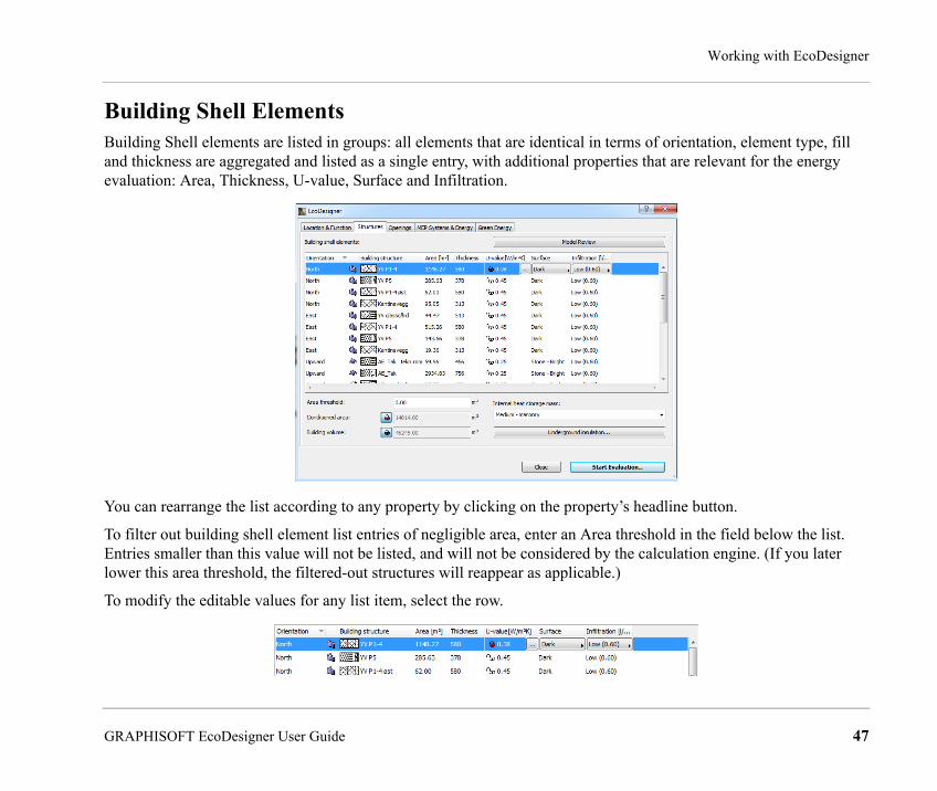
Working with EcoDesigner
Building Shell ElementsBuilding Shell elements are listed in groups: all elements that are identical in terms of orientation, element type, fill and thickness are aggregated and listed as a single entry, with additional properties that are relevant for the energy evaluation: Area, Thickness, U-value, Surface and Infiltration.
You can rearrange the list according to any property by clicking on the property’s headline button.
To filter out building shell element list entries of negligible area, enter an Area threshold in the field below the list. Entries smaller than this value will not be listed, and will not be considered by the calculation engine. (If you later lower this area threshold, the filtered-out structures will reappear as applicable.)
To modify the editable values for any list item, select the row.
GRAPHISOFT EcoDesigner User Guide 47

Working with EcoDesigner
For information on U-value, see U-value (R-value) Calculator.To edit multiple entries of the Building Shell Elements List, select the entry that needs to be modified. Then add further entries to the selection by moving the pointer with the mouse without releasing the left mouse button, or by clicking on the entries while pressing the CTRL or the SHIFT key.
Use the function buttons (see Surface, Infiltration and U-value (R-value) Calculator) that appear by the first selected line to modify properties of all selected list entries.
48 GRAPHISOFT EcoDesigner User Guide

Working with EcoDesigner
SurfaceThe Surface property determines the absorption properties of the selected Building Shell Element. Click the pop-up arrow in this field to select from a list of surface materials and finishes.
Default absorbance percentage values linked to each available material are stored in the DefaultValues.xml file (see Localized EcoDesigner Contents – the XML Files).
<DefaultValue Name="Structure.Surface.SolarAbs.DarkColoredPlaster" Value="85" />
<DefaultValue Name="Structure.Surface.SolarAbs.MediumColoredPlaster" Value="50" />
<DefaultValue Name="Structure.Surface.SolarAbs.LightColoredPlaster" Value="8" />
<DefaultValue Name="Structure.Surface.SolarAbs.DarkStone" Value="65" />
Examples of solar absorbance values linked to surface properties
Users may alter the numeric percentage values, but may not change material names or add new materials to the Surface popup.
GRAPHISOFT EcoDesigner User Guide 49

Working with EcoDesigner
InfiltrationInfiltration (unit: l/s,m2) refers to the air permeability of the selected structure group. Click the pop-up arrow in this field to select the option that best describes the structure’s infiltration level:
Default infiltration settings are located in the DefaultValues.xml file (see Localized EcoDesigner Contents – the XML Files).
<DefaultValue Name="Structure.Infiltration.Airtight" Value="0" /><DefaultValue Name="Structure.Infiltration.Low" Value="0.6" /><DefaultValue Name="Structure.Infiltration.Average" Value="1.1" /><DefaultValue Name="Structure.Infiltration.High" Value="1.6" />
Values associated to the different levels of infiltration
Users may edit the numeric values but may not change infiltration level names or add new levels to the Infiltration popup.
50 GRAPHISOFT EcoDesigner User Guide

Working with EcoDesigner
U-value (R-value) CalculatorSelect any structure in the list. In the U-value column, click the three-dot button - with the lock icon set to closed (red) - to bring up the U-value Calculator dialog.
U-value refers to the heat transmission coefficient of the selected Building Shell Element. Use the U-value Calculator to estimate the thermal physics performance of materials and composite structures in your project.
In the U-value Calculator, the skins that make up the selected structure are listed with their relevant properties (Thickness, Thermal conductivity, Density and Heat capacity), each showing a default value. If needed, you can edit any of these values manually. (See Thermal Property Assignment below.)
Depending on local convention, you may prefer to use the R value (Thermal Resistance Coefficient), which is the inverse of the U value. To list and display R values instead of U values (both here and in the final Evaluation Report), click the U-value pop-up at the bottom right of this dialog box, and choose R-value.
For each selected skin, the U-value Calculator calculates the average heat transmission coefficient value based on a simplified algorithm. This algorithm relies on these properties plus three additional, manually editable static values (shown at bottom left): External and Internal heat transfer coefficients, and the Thermal bridge effect related to structural surface area.
It is recommended to review the default Thermal bridge effect provided by EcoDesigner for ArchiCAD 15 and to adjust it manually, as this value may vary greatly, according to composite type and the design of the building construction details.
The Calculated U-value is displayed in the bottom right corner of the panel.
GRAPHISOFT EcoDesigner User Guide 51

Working with EcoDesigner
Note: The Calculated U-value shown in this dialog box is an initial approximation that is used by most national standards. However, the energy evaluation carried out by EcoDesigner uses a more accurate dynamic calculation algorithm that evaluates heat transmission of the building envelope structures at every hour throughout one year. The result of this dynamic analysis is the basis of the Energy Consumption, Carbon Footprint and Monthly Energy Balance data displayed on the Energy Evaluation Report. (See Building Energy Evaluation Report.)
U-value (R-value) Calculation AlgorithmThe U-value Calculator calculates the average heat transmission coefficient of materials and composite structures, based on a stationary algorithm that is used by most national standards. Some local conventions prefer to use the R value (Thermal Resistance Coefficient), which is the inverse of the U value. EcoDesigner supports the use of the R value in addition to the U value.
To include the effects of thermal bridges, delta U-values are added to the average U-values of structure group entries. The magnitudes of external and internal heat transfer coefficients and the delta U-value depend on the position of the evaluated structure relative to the thermal current. Default settings are offered within EcoDesigner.
Default heat transfer coefficients and delta U-values
Position of structure relative to the thermal current
EcoDesigner orientation External HTC Internal HTC Thermal bridge effect (delta U)
Default settings available within EcoDesigner
External wall 8 default points of the compass 24 8 0,11
Roof upward 24 10 0,04
Basement wall underground 0 0 0
Further suggested settings
Slab below unheated attic upward 12 10 0,04
52 GRAPHISOFT EcoDesigner User Guide

Working with EcoDesigner
It is advisable to review and manually override these predefined values if the structural situation demands or if the standards for the project location are different.
To correctly evaluate thermal insulated slabs (see Shell Slabs), besides the settings detailed above, define their surfaces as “reflective” on the Building shell elements list.
Note: The result displayed in the Energy Evaluation Report is based on a dynamic calculation algorithm that is more accurate than the static method described above. The dynamic method determines the heat transmission through the building envelope structures at every hour throughout an entire year.
Thermal Property AssignmentView the skins listed in the U-value calculator. While the fill type, name and thickness of each skin is derived from the element’s settings in ArchiCAD, the three material properties to the right of the vertical line - Thermal conductivity, Density and Heat capacity - can be modified by you, if the default values here do not correspond to your actual project structures.
To change the Thermal conductivity, Density and/or Heat capacity value of any skin, select it from the list in the U-value Calculator.
Slab above unheated attic upward 8 6 0,09
Slab above arcade upward 20 6 0,05
Wall between heated and unheated internal spaces
8 default points of the compass 8 8 0,04
Default heat transfer coefficients and delta U-values
GRAPHISOFT EcoDesigner User Guide 53
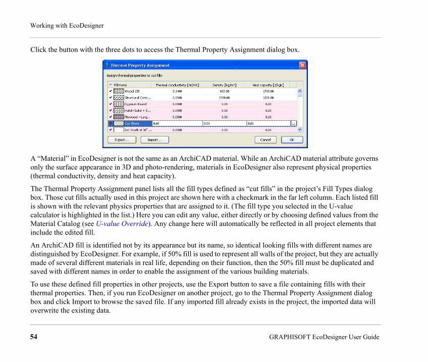
Working with EcoDesigner
Click the button with the three dots to access the Thermal Property Assignment dialog box.
A “Material” in EcoDesigner is not the same as an ArchiCAD material. While an ArchiCAD material attribute governs only the surface appearance in 3D and photo-rendering, materials in EcoDesigner also represent physical properties (thermal conductivity, density and heat capacity).
The Thermal Property Assignment panel lists all the fill types defined as “cut fills” in the project’s Fill Types dialog box. Those cut fills actually used in this project are shown here with a checkmark in the far left column. Each listed fill is shown with the relevant physics properties that are assigned to it. (The fill type you selected in the U-value calculator is highlighted in the list.) Here you can edit any value, either directly or by choosing defined values from the Material Catalog (see U-value Override). Any change here will automatically be reflected in all project elements that include the edited fill.
An ArchiCAD fill is identified not by its appearance but its name, so identical looking fills with different names are distinguished by EcoDesigner. For example, if 50% fill is used to represent all walls of the project, but they are actually made of several different materials in real life, depending on their function, then the 50% fill must be duplicated and saved with different names in order to enable the assignment of the various building materials.
To use these defined fill properties in other projects, use the Export button to save a file containing fills with their thermal properties. Then, if you run EcoDesigner on another project, go to the Thermal Property Assignment dialog box and click Import to browse the saved file. If any imported fill already exists in the project, the imported data will overwrite the existing data.
54 GRAPHISOFT EcoDesigner User Guide
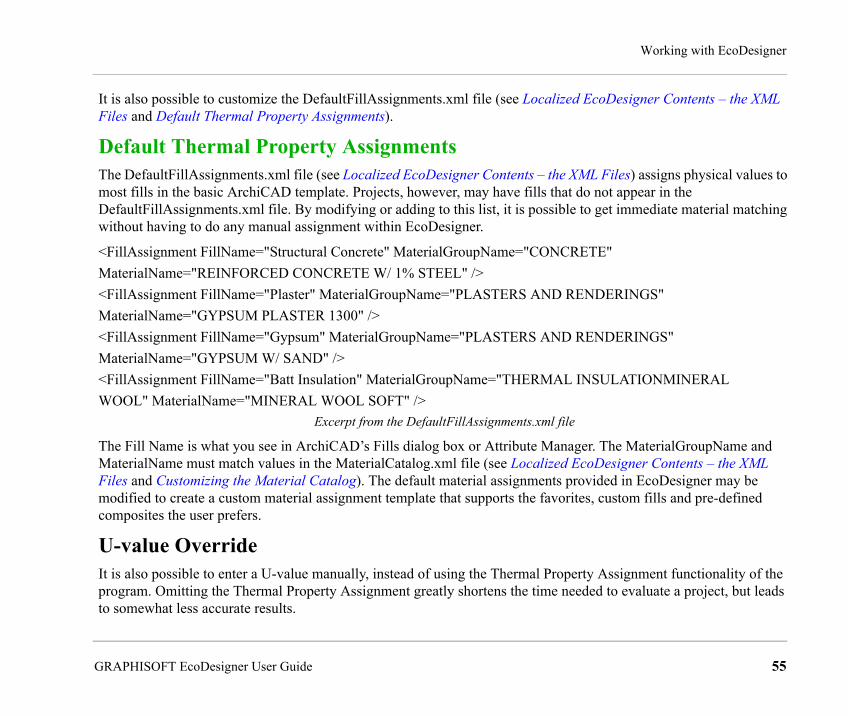
Working with EcoDesigner
It is also possible to customize the DefaultFillAssignments.xml file (see Localized EcoDesigner Contents – the XML Files and Default Thermal Property Assignments).
Default Thermal Property AssignmentsThe DefaultFillAssignments.xml file (see Localized EcoDesigner Contents – the XML Files) assigns physical values to most fills in the basic ArchiCAD template. Projects, however, may have fills that do not appear in the DefaultFillAssignments.xml file. By modifying or adding to this list, it is possible to get immediate material matching without having to do any manual assignment within EcoDesigner.
<FillAssignment FillName="Structural Concrete" MaterialGroupName="CONCRETE"MaterialName="REINFORCED CONCRETE W/ 1% STEEL" /><FillAssignment FillName="Plaster" MaterialGroupName="PLASTERS AND RENDERINGS"MaterialName="GYPSUM PLASTER 1300" /><FillAssignment FillName="Gypsum" MaterialGroupName="PLASTERS AND RENDERINGS"MaterialName="GYPSUM W/ SAND" /><FillAssignment FillName="Batt Insulation" MaterialGroupName="THERMAL INSULATIONMINERALWOOL" MaterialName="MINERAL WOOL SOFT" />
Excerpt from the DefaultFillAssignments.xml file
The Fill Name is what you see in ArchiCAD’s Fills dialog box or Attribute Manager. The MaterialGroupName and MaterialName must match values in the MaterialCatalog.xml file (see Localized EcoDesigner Contents – the XML Files and Customizing the Material Catalog). The default material assignments provided in EcoDesigner may be modified to create a custom material assignment template that supports the favorites, custom fills and pre-defined composites the user prefers.
U-value OverrideIt is also possible to enter a U-value manually, instead of using the Thermal Property Assignment functionality of the program. Omitting the Thermal Property Assignment greatly shortens the time needed to evaluate a project, but leads to somewhat less accurate results.
GRAPHISOFT EcoDesigner User Guide 55

Working with EcoDesigner
Select any structure in the list. In the U-value column, click the three-dot button - with the lock icon set to open (white) - to bring up the U-value Override dialog.
Use this dialog to enter the target U-value and select the thermal mass (Lightweight, Medium or Heavyweight) of the selected structure group, instead of using the materials coming from the building model directly (see U-value (R-value) Calculator).
56 GRAPHISOFT EcoDesigner User Guide

Working with EcoDesigner
Material CatalogIn the Thermal Property Assignment dialog box, highlight a row and click the right-side button with three dots: this brings up the EcoDesigner Material Catalog.
The Material Catalog is an extensive database integrated within EcoDesigner that contains building material information relevant for the energy calculations (Thermal conductivity, Density and Heat capacity). The building materials are grouped in main categories with drop-down detailed lists to enable easy access and quick selection.
Select a material here whose physical properties correspond to your needs. When you click OK in the Material Catalog, the thermal properties of the selected material are assigned to the skin you selected in Thermal Property Assignment.
This way, the calculation engine obtains the physical data required for the thermal evaluation without any numeric input from you.
GRAPHISOFT EcoDesigner User Guide 57

Working with EcoDesigner
Customizing the Material CatalogThe MaterialCatalog.xml file (see Localized EcoDesigner Contents – the XML Files) lists materials in groups. The user can add new groups and materials or rename existing ones, but changes made here must also be done in the DefaultFillAssignments.xml file (see Localized EcoDesigner Contents – the XML Files and Default Thermal Property Assignments). These modifications also affect the manual assignments made in other project previously.
<MaterialGroup Name="FLOOR COVERINGS"><Material Name="CARPET" ThermalConduct="0.06" Density="200" HeatCapacity="1300" /> <Material Name="LINOLEUM" ThermalConduct="0.17" Density="1200" HeatCapacity="1400" /> <Material Name="PLASTIC FLOOR" ThermalConduct="0.25" Density="1700" HeatCapacity="1400" /> <Material Name="RUBBER FLOOR" ThermalConduct="0.17" Density="1200" HeatCapacity="1400" /> <Material Name="TEXTILE FLOOR" ThermalConduct="0.06" Density="200" HeatCapacity="1300" /> <Material Name="CORK FLOOR" ThermalConduct="0.065" Density="400" HeatCapacity="1500" /> <Material Name="CELLULAR RUBBER UNDERLAY" ThermalConduct="0.1" Density="270" HeatCapacity="1400" /> <Material Name="CORK UNDERLAY" ThermalConduct="0.05" Density="200" HeatCapacity="1500" /> <Material Name="FELT UNDERLAY" ThermalConduct="0.05" Density="120" HeatCapacity="1300" /> <Material Name="PLASTIC UNDERLAY" ThermalConduct="0.1" Density="270" HeatCapacity="1400" /> <Material Name="WOOL UNDERLAY" ThermalConduct="0.06" Density="200" HeatCapacity="1300" /> </MaterialGroup>
Excerpt from the MaterialCatalog.xml file –The Floor Coverings group
58 GRAPHISOFT EcoDesigner User Guide

Working with EcoDesigner
Building GeometryBelow the Building Shell Elements list of the Structures tab page, the Conditioned area and the Building volume values are displayed. These are calculated by the Automatic Model Analysis, but you can edit them manually if needed. (see also Show/Hide Building Volume.)
Manual correction of the Building volume data generated by the Automatic Model Analysis may be necessary if the shape of the building is significantly different from the shape of the conditioned building volume (e.g. the design includes many unconditioned spaces).
You can fix the Conditioned area and the Building volume values by clicking on the lock icons next to them.
Inaccurate element connections due to improperly constructed ArchiCAD models may produce open floor area polygons and, as a result, incorrect volumes may be generated by EcoDesigner. In this case the user has two ways to obtain the correct data:
• Fix the incorrect element connections of the ArchiCAD model, then select the “Reanalyze model” function button on the Model Review palette.
• Modify the value of the Building volume via numerical input on the Structures tab page of the EcoDesigner dialog box. To do this, the user must calculate the Conditioned floor area and Building volume manually.
GRAPHISOFT EcoDesigner User Guide 59

Working with EcoDesigner
ArchiCAD’s numerous helpful conventional documentation tools, such as dimension markers, zone stamps or fills with area markers turned on, help the user to obtain the necessary height and area data quickly, from which the building volume may easily be calculated.
Internal Heat Storage MassUse this pop-up list to describe the building’s Internal heat storage mass, using one of the three available options:
The threshold values for these categories are:
• heavy-weight: > 400 kg/floor area
• medium: 250 – 400 kg/floor area
• light-weight: <250 kg/floor area
Within EcoDesigner, these predefined settings are linked to mean density values. These density values are multiplied by the total volume of the interior structures (see Building Geometry), providing the numeric Internal heat storage mass value to the calculation engine.
Underground InsulationUnderground Insulation data are needed to determine the linear thermal currents characteristic of structures that are in contact with the ground. In EcoDesigner, these values are applied to:
• Basement Floors, and
• Floors on Ground
Note: Basement Walls are not considered when defining Underground Insulation; their properties are defined in the Building Shell Elements List (Orientation: Underground) of the Structures panel.
Click the Underground Insulation button to bring up a dialog box of the same name.
For insulation material, click the three-dot button to access the Material Catalog (the same one used to enter values in the U-value calculator.) (See U-value Override.)
60 GRAPHISOFT EcoDesigner User Guide

Working with EcoDesigner
Select a material here whose thermal properties correspond to the underground insulation used in your building.
Enter a value for insulation thickness: you must enter this data manually.
Advanced Handling of Underground InsulationIn certain cases, it is not easy to determine this thickness, as the thermal current passes through more than one layer of thermal insulation.
The user, first of all, should determine the critical thermal current, which travels the path of least resistance – through the least total thermal insulation, considering the different properties of the various thermal insulation materials. The detail above displays a frost resistant footing joint to a floor on ground. The floor has a 1,5m wide strip of thermal insulation around its perimeter to limit the thermal bridge effect. Relevant thermal currents are indicated by red arrows (numbered 1, 2 and 3). Even though currents 2 and 3 only pass through a single layer of thermal insulation, they also need to travel through a thicker layer of soil. Therefore current 1 represents the path of least thermal resistance.
For insulation thickness, the sum of the horizontal floor perimeter thermal insulation and the thermal insulation on the footing (d1 +d2) must be entered. This sum, divided by the thermal conductivities of the insulation materials, equals the thermal resistance of the analyzed detail. EcoDesigner uses these resistance values and the vertical displacements (indicated by ‘Z’ on the detail above.) of the floors compared to the grade level (see Grade Level to Project Zero) of the project (derived from the Grade level to project zero settings and the floors’ positions relative to Project Zero) to determine the linear heat transmission coefficients at each different relevant detail.
GRAPHISOFT EcoDesigner User Guide 61

Working with EcoDesigner
The model analysis function (see Automatic Model Analysis) calculates the perimeter lengths of each structure that is in contact with the ground (marked with green and red lines on the axonometry above). The matching linear heat transmission coefficients and length values are multiplied, then eventually summed to obtain the effect of the most significant linear heat losses.
OpeningsThe Openings tab page of the EcoDesigner dialog box lists data for all of the Openings on the building shell, by orientation and opening type.
Note: Openings are not listed one by one; instead, the data are totaled for the opening type and orientation. For example, the first row in our image lists the total data for all windows in the North orientation that have been modeled using a single ArchiCAD opening type.
62 GRAPHISOFT EcoDesigner User Guide

Working with EcoDesigner
For each orientation, the following data are shown:
• the opening type’s total surface Area
• Shading device used
• Glass %: percentage of transparent surface compared to total surface area
• U-value: heat transmission coefficient
• TST %: Total Solar Transmission compared to transparent glass
• Infiltration: air permeability of the selected structure
You can rearrange the list according to any property by clicking on the property’s headline button.
Note the line at the left of the Shading device column: properties to the left of this line are generated by your project elements. Properties to the right of this line, however, can be modified by you.
When one of the Transparent openings list entries is highlighted, the Shading device selection button (see Shading Devices) appears, plus a button with three dots, which opens the Openings Catalog (see Openings Catalog).
To change the Glass%, U-value, TST% and/or Infiltration level for the selected opening, either edit the value manually, or use the predefined value sets from the Openings Catalog (see Openings Catalog).
GRAPHISOFT EcoDesigner User Guide 63

Working with EcoDesigner
Shading DevicesClick the arrow on the Shading device field to apply a shading device, with its predefined physical properties, to the selected entry.
Custom Shading DevicesThese default properties are stored in the ShadingCatalog.xml (see Localized EcoDesigner Contents – the XML Files) in a similar manner as the properties defining the different levels of elevation complexity (see Custom Façade Shadings).
<Shading Name="External Adjustable Louvre" ID="106">
<LimitTemperature>22.0</LimitTemperature>
<LimitEffect>2500.0</LimitEffect>
<TotalShadeFactorReduction>90.0</TotalShadeFactorReduction>
<DirectShadeFactorReduction>90.0</DirectShadeFactorReduction>
<HorizontalUpperEdgeAngle>0.0</HorizontalUpperEdgeAngle>
64 GRAPHISOFT EcoDesigner User Guide
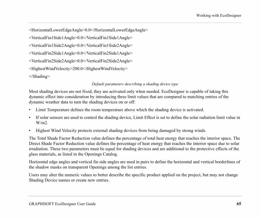
Working with EcoDesigner
<HorizontalLowerEdgeAngle>0.0</HorizontalLowerEdgeAngle>
<VerticalFin1Side1Angle>0.0</VerticalFin1Side1Angle>
<VerticalFin1Side2Angle>0.0</VerticalFin1Side2Angle>
<VerticalFin2Side1Angle>0.0</VerticalFin2Side1Angle>
<VerticalFin2Side2Angle>0.0</VerticalFin2Side2Angle>
<HighestWindVelocity>200.0</HighestWindVelocity>
</Shading>
Default parameters describing a shading device type
Most shading devices are not fixed; they are activated only when needed. EcoDesigner is capable of taking this dynamic effect into consideration by introducing three limit values that are compared to matching entries of the dynamic weather data to turn the shading devices on or off:
• Limit Temperature defines the room temperature above which the shading device is activated.
• If solar sensors are used to control the shading device, Limit Effect is set to define the solar radiation limit value in W/m2.
• Highest Wind Velocity protects external shading devices from being damaged by strong winds.
The Total Shade Factor Reduction value defines the percentage of total heat energy that reaches the interior space. The Direct Shade Factor Reduction value defines the percentage of heat energy that reaches the interior space due to solar irradiation. These two parameters must be equal for shading devices and are additional to the protective effects of the glass materials, as listed in the Openings Catalog.
Horizontal edge angles and vertical fin side angles are used in pairs to define the horizontal and vertical borderlines of the shadow masks on transparent Openings among the list entries.
Users may alter the numeric values to better describe the specific product applied on the project, but may not change Shading Device names or create new entries.
GRAPHISOFT EcoDesigner User Guide 65

Working with EcoDesigner
Openings CatalogSelect an item from the Openings tab page and click the three-dot button to access EcoDesigner’s built-in Openings Catalog.
The Openings Catalog is an extensive database of building physics information relevant for the energy calculations: Glass %, U-value, TST % and Infiltration. The structures that may be built into openings on the building shell are grouped in main categories (windows/glazed doors/curtain wall glazing, air inlet valves, external doors and skylights) that drop down in detailed lists to enable easy access and quick selection.
You may encounter unfamiliar data in the listed opening names.
For example: WOOD/4-12-4-12-4/COATING e=0.05/ARGON
This means:
• WOOD: material of frame • 4-12-4-12-4: window layers: 4mm glass, 12 mm air space, 4 mm glass, etc. • COATING e=0.05: the outside glass layer is coated with a “low-emittance (Low-E) coating” that reduces U-factor
by reducing the radiative heatflow. The lower this factor, the lower the total heat flow through the window. • ARGON: The gas used to fill the air space between the glass layers.
66 GRAPHISOFT EcoDesigner User Guide
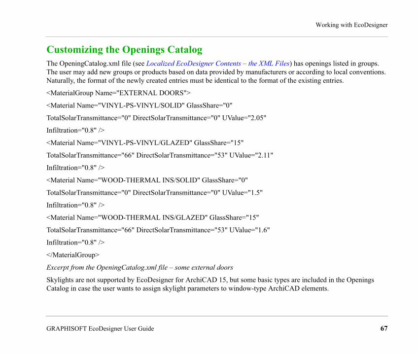
Working with EcoDesigner
Customizing the Openings CatalogThe OpeningCatalog.xml file (see Localized EcoDesigner Contents – the XML Files) has openings listed in groups. The user may add new groups or products based on data provided by manufacturers or according to local conventions. Naturally, the format of the newly created entries must be identical to the format of the existing entries.
<MaterialGroup Name="EXTERNAL DOORS">
<Material Name="VINYL-PS-VINYL/SOLID" GlassShare="0"
TotalSolarTransmittance="0" DirectSolarTransmittance="0" UValue="2.05"
Infiltration="0.8" />
<Material Name="VINYL-PS-VINYL/GLAZED" GlassShare="15"
TotalSolarTransmittance="66" DirectSolarTransmittance="53" UValue="2.11"
Infiltration="0.8" />
<Material Name="WOOD-THERMAL INS/SOLID" GlassShare="0"
TotalSolarTransmittance="0" DirectSolarTransmittance="0" UValue="1.5"
Infiltration="0.8" />
<Material Name="WOOD-THERMAL INS/GLAZED" GlassShare="15"
TotalSolarTransmittance="66" DirectSolarTransmittance="53" UValue="1.6"
Infiltration="0.8" />
</MaterialGroup>
Excerpt from the OpeningCatalog.xml file – some external doors
Skylights are not supported by EcoDesigner for ArchiCAD 15, but some basic types are included in the Openings Catalog in case the user wants to assign skylight parameters to window-type ArchiCAD elements.
GRAPHISOFT EcoDesigner User Guide 67

Working with EcoDesigner
MEP Systems and EnergyUse this tab page to input data on the MEP systems planned for the building.
Energy SourcePress the Fuel button to open the Energy source dialog.
The Fuel button is active:
• under Heating type if Local boiler/water heater or District heating is selected
• under Cooling type if District cooling is selected
• under Hot water generation if the Heating Target is set to Heating only (in other words: a separate system is installed for hot water generation besides the heating system).
68 GRAPHISOFT EcoDesigner User Guide

Working with EcoDesigner
Use the dropdown to specify energy sources (Natural gas, Propane, Oil, Wood, Coal, Electricity or Pellet) for the purpose of Heating, Cooling and Hot water generation, respectively.
If you use more than one energy source for a function, click the + button, then choose an additional energy source. Define the proportion of each source used so that they add up to 100% in the Energy source dialog.
To remove a row, click the – button.
Heating TypeChoose one of the three options to describe the building’s heating system.
• The Natural heating option has been developed for warm climate countries, where the annual energy required for heating is very low. The installation of a heating system is not necessary, provided that inhabitants can tolerate the fact that internal air temperature drops below the prescribed level on a couple of chilly nights or mornings a year. Set Heating type to natural in such cases: the calculation engine of EcoDesigner will assume that the external air is sufficient for heating purposes.
• The Local boiler/water heater option should be selected if these energy supplies are provided by a local system that only feeds the project you are evaluating.
• District heating means that the evaluated building’s heating and/or hot water needs are supplied by an external plant in the form of hot water or steam through a pipeline. If scaled and designed correctly, district heating is a more efficient alternative to local boilers. This is why it is a very wide-spread heating type in Europe.
Efficiency: fine-tune the selected Heating type’s efficiency using the editable field if the project’s heating system plans are already available, or else use the mean efficiency values that appear for each Heating type.
Target: define whether the project’s heating system is for Heating and hot water generation or for Heating only, by selecting the appropriate option:
• If Heating only is selected, then the Fuel button under the separate Hot water generation settings remains active, allowing the definition of a water heating system that is separate from the heating system.
• If Heating and hot water is selected, then the Fuel button under the separate Hot water generation settings becomes inactive, indicating that the same heater is used for Heating and Hot water generation. The Cold and Hot water temperature settings, in this case, apply to the combined heater defined at Heating type.
GRAPHISOFT EcoDesigner User Guide 69
Working with EcoDesigner
Cooling TypeChoose one of the four options to describe the building’s cooling system.
• Natural cooling involves no MEP systems; natural air currents are used to cool the building. Even though this method is considered the most eco-friendly, it has its limitations, as the temperature of the external air is not always sufficient for cooling purposes. (If Natural cooling is selected, the calculation engine of EcoDesigner assumes that the external air is sufficient for cooling purposes, and leaves it up to the user to verify this assumption.)
• Mechanical cooling means that some type of air conditioning system is to be installed in the building. For air conditioning type, either Water-cooled or Air-cooled may be defined.
• District cooling: In certain countries, conditioned air may be obtained from an external source. If the building will be connected to such an external cooling system, select District cooling and use the Fuel button (see Energy Source) to define the source or multiple sources of energy used by the district cooling plant.
• Heat pump for cooling: Select this option if a heat pump will be installed to achieve cooling using sustainable energy. Select the appropriate energy source (groundwater, sea, soil, external air or exhaust air) from the dropdown list.Note: The Heat pump settings on the Green Energy tab page do not influence the Heat pump for cooling.
Ventilation TypeSpecify the type of ventilation used in the building, then enter a value for the hourly air change rate. This target value depends on national standards, and will vary depending on the building’s function and the local climate.
• Natural ventilation involves no MEP systems: natural air currents drive fresh air into the building and used air out of it. From an ecological point of view, natural ventilation is preferable to mechanical solutions, but due to its limited controllability its use is largely limited to residential buildings.
For building functions other than residential, the standards usually prescribe strict target air exchange values, which necessitate a mechanical ventilation system of some sort:
• Exhaust-only systems rely on fans to extract used air from the rooms.
• Supply and exhaust systems mechanically control both the air intake and outlet procedure, thus enabling the exact programming of the Air change per hour.
70 GRAPHISOFT EcoDesigner User Guide

Working with EcoDesigner
Hot Water GenerationEnter Cold and Hot water temperature target values. The calculation engine uses this data to calculate the energy consumption related to hot water generation.
To change the temperature scale (Celsius or Fahrenheit), click the arrow button next to the input field.
Note: For other units (apart from temperature scale), EcoDesigner uses the units defined in ArchiCAD, at Options > Project Preferences > Calculation Units. (See Calculation Unit Settings.)
Use the Fuel button (see Energy Source) to define the source or multiple sources of energy consumed by the water heater.
Interior LightingSelect a Fitting type from the options offered by the dropdown list. The default Lighting power densities (LPD) assigned to the Fitting types appear in the editable LPD field. This field allows users to fine-tune the default LPD value if the lighting design of the project is already available at the time of the evaluation.
Fitting type Default LPD [W/m2]Incandescent 10Fluorescent lighting tube 5Compact fluorescent 3LED light 0,5Custom -
GRAPHISOFT EcoDesigner User Guide 71

Working with EcoDesigner
Energy Source FactorsClick the Energy source factors button on the MEP Systems and Energy panel to bring up the dedicated dialog box.
The primary energy (see Primary Energy) source factors and CO2 emission (see Carbon Footprint) factors assigned to the energy sources differ according to building location (see Location and Function). Use this dialog to enter the region-specific data if available, or evaluate the project using the default assignments offered by EcoDesigner (based on standard DINV-18599).
At the bottom of the Energy Source Factors dialog, define the building’s source or multiple sources of electricity. Use the dropdown to specify the source of electricity (Natural gas, Propane, Oil, Wood, Coal, Nuclear energy, Wind energy, Solar energy, Water energy or Unknown). If you use more than one energy source, click the + button, then choose an additional source. Define the Proportion of each source used so that they add up to 100%. To remove a row, click the - button.
72 GRAPHISOFT EcoDesigner User Guide

Working with EcoDesigner
Energy CostsClick the Energy costs button on the MEP Systems and Energy panel to bring up the dedicated dialog box.
In the top part of the panel, enter the currency name or its abbreviation in the Displayed currency unit field.
Use the bottom part of the panel to define the Prices of purchased energy. These prices, of course, vary by location and therefore must be entered numerically by the user. Select the Unit of energy (e.g. kWh) from the dropdown list. Next, select a row representing a source of energy, and then enter the price, in the currency you chose.
GRAPHISOFT EcoDesigner User Guide 73

Working with EcoDesigner
Green EnergyUse this tab page to input data on MEP systems that utilize sustainable resources.
Energy recovery systems can significantly increase the efficiency of the building’s MEP system. Some extra initial investment in the construction phase can pay off, by regaining otherwise wasted energy or obtaining additional energy from sustainable external input such as solar irradiation or geothermic energy.
Solar CollectorSolar thermal collector panels are designed to collect heat by absorbing sunlight and converting the energy in solar radiation into a more usable form.
If the building is equipped with solar collectors, check the Solar collector box, then specify the collector geometry data required for the calculations, by entering the collector’s area, angle to the South (or to the North, for southern hemisphere locations) and its tilt angle, as indicated by the icons.
74 GRAPHISOFT EcoDesigner User Guide

Working with EcoDesigner
Use the checkboxes to set one or more of the following targets for the recovered solar energy.
• Space heating
• Fresh air heating
Note: Fresh air heating requires installed mechanical ventilation.
• Hot water generation
Note: If solar collectors are used for multiple targets, then Hot water generation always has the highest priority. This means that if the solar collector is unable to generate enough energy to feed all targets, then it is going to feed the water heater first and use the remaining available energy for the other targets.
Air to air energy recoveryNote: The Air to air recovery controls are available only if you have chosen a ventilation system that involves mechanical exhaust. If your ventilation type is set to Natural (see MEP Systems and Energy) these controls are inactive and a warning appears, informing the user that Air to air recovery requires installed mechanical ventilation.
An air to air energy recovery system can regain a percentage of the heat content of mechanically expelled ventilation air.
If such a system is to be installed, check the “Air to air energy recovery” box, then choose the type of your air to air energy recovery system: Fixed plate, Rotary or Coil:
• A fixed plate heat exchanger uses fixed metal plates to transfer heat between exhaust and fresh air flow without any moving parts.
• Rotary heat exchangers provide a compact solution for heat recovery from exhaust air. They require motors to turn the recovery wheel, which transfers the heat from the exhaust air to the fresh air.
• Coil: the most common heat exchangers are called coils due to their usually serpentine internal tubing. These use water-glycol solution to recover heat from exhaust air.
Enter a percentage that approximates the system’s anticipated efficiency value.
GRAPHISOFT EcoDesigner User Guide 75
Working with EcoDesigner
Heat PumpIf a heat pump system is planned, check the “Heat Pump” box, then specify the heat source.
The available options are Groundwater, Sea, Soil, External air and Exhaust air (see also Heat pump for cooling at Cooling Type).
Specify the system’s capacity, in the units defined for your project (e.g. kilowatts).
Next, specify the targeted use of this energy using the checkboxes.
• Space heating
• Fresh air heating
Note: Fresh air heating requires installed mechanical ventilation.
• Hot water generation
Note: If heat pump is used for multiple targets, then Hot water generation always has the highest priority. This means that if the heat pump is unable to generate enough energy to feed all targets, then it is going to feed the water heater first and use the remaining available energy for the other targets.
76 GRAPHISOFT EcoDesigner User Guide

Working with EcoDesigner
Export to PHPPThe Export to PHPP button activates the PHPP Export dialog box, which enables you to send building information model data to the PHPP 2007 Excel workbook you specify, for post processing.
PHPP is the official Excel workbook created by the Darmstadt Passivhaus Institute, to calculate the energy demands of Passivhaus projects. Passivhaus is a design directive that aims to realize extremely low energy projects (mainly small scale residential) in a relatively simple manner, by following certain strict yet straightforward design guidelines.
GRAPHISOFT EcoDesigner User Guide 77

Working with EcoDesigner
Note: the PHPP 2007 Excel workbook is an independent product of the Darmstadt Passivhaus Institute and is not a part of GRAPHISOFT EcoDesigner. For more information on PHPP and the Passivhaus Institute visit the official website at http://www.passiv.de/
The directive sets stringent threshold values for the Specific annual net heating and cooling demands (15 kilo watt hours per square meter, year maximum), total annual specific primary energy demand (less than 120 kilo watt hours per square meter, year), and average infiltration (maximum 0.6 1/h).
Note: The Key Values section of the EcoDesigner Building Energy Evaluation Report displays these performance data, as calculated by The VIPCore Calculation Engine.
Use the PHPP Export panel to browse for the official PHPP 2007 Excel workbook to be used as a template, then save the project-specific PHPP Excel file under a different name.
78 GRAPHISOFT EcoDesigner User Guide
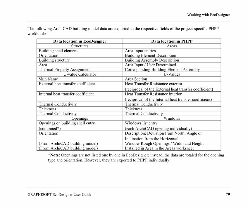
Working with EcoDesigner
The following ArchiCAD building model data are exported to the respective fields of the project-specific PHPP workbook:
*Note: Openings are not listed one by one in EcoDesigner; instead, the data are totaled for the opening type and orientation. However, they are exported to PHPP individually.
Data location in EcoDesigner Data location in PHPPStructures Areas
Building shell elements Area Input entriesOrientation Building Element DescriptionBuilding structure Building Assembly DescriptionArea Area Input / User Determined Thermal Property Assignment Corresponding Building Element Assembly
U-value Calculator U-ValuesSkin Name Area SectionExternal heat transfer coefficient Heat Transfer Resistance exterior
(reciprocal of the External heat transfer coefficient)Internal heat transfer coefficient Heat Transfer Resistance interior
(reciprocal of the Internal heat transfer coefficient)Thermal Conductivity Thermal ConductivityThickness ThicknessThermal Conductivity Thermal Conductivity
Openings WindowsOpenings on building shell entry (combined*)
Windows list entry(each ArchiCAD opening individually)
Orientation Description; Deviation from North; Angle of Inclination from the Horizontal
(From ArchiCAD building model) Window Rough Openings / Width and Height(From ArchiCAD building model) Installed in Area in the Areas worksheet
GRAPHISOFT EcoDesigner User Guide 79
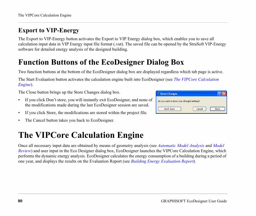
The VIPCore Calculation Engine
Export to VIP-EnergyThe Export to VIP-Energy button activates the Export to VIP Energy dialog box, which enables you to save all calculation input data in VIP Energy input file format (.vut). The saved file can be opened by the StruSoft VIP-Energy software for detailed energy analysis of the designed building.
Function Buttons of the EcoDesigner Dialog BoxTwo function buttons at the bottom of the EcoDesigner dialog box are displayed regardless which tab page is active.
The Start Evaluation button activates the calculation engine built into EcoDesigner (see The VIPCore Calculation Engine).
The Close button brings up the Store Changes dialog box.
• If you click Don’t store, you will instantly exit EcoDesigner, and none of the modifications made during the last EcoDesigner session are saved.
• If you click Store, the modifications are stored within the project file.
• The Cancel button takes you back to EcoDesigner.
The VIPCore Calculation EngineOnce all necessary input data are obtained by means of geometry analysis (see Automatic Model Analysis and Model Review) and user input in the Eco Designer dialog box, EcoDesigner launches the VIPCore Calculation Engine, which performs the dynamic energy analysis. EcoDesigner calculates the energy consumption of a building during a period of one year, and displays the results on the Evaluation Report (see Building Energy Evaluation Report).
80 GRAPHISOFT EcoDesigner User Guide

The VIPCore Calculation Engine
Conditions for Starting the EvaluationAs long as EcoDesigner detects that any of the required input data is insufficient, the Start Evaluation function button at the bottom of the EcoDesigner dialog box remains inactive. In order to start the energy evaluation, you must first make the necessary corrections.
In the EcoDesigner dialog box (see Additional User Input), a yellow warning exclamation mark appears next to those entries which contain faulty or missing data. (The problematic list items are also highlighted in pink.)
The most common reasons for invalid/missing data are:
• No weather data is available for the specified building location coordinates (see Project Location). This may occur if the weather data for the coordinates are not available by default within EcoDesigner, and the computer is not connected to the Internet, thus unable to obtain the data from the Online Weather Database server.
• No material is assigned to some ArchiCAD fills used in the project (see Thermal Property Assignment), so some structures have invalid heat transmission coefficients (see U-value (R-value) Calculator). In this case, the error sign appears next to the affected entry of the Building shell elements list (see Building Shell Elements).
• The Building volume or Heated floor area (see Building Geometry) has been given a value of zero by the user, on the Structures tab page of the EcoDesigner dialog box.
• Some openings on the building shell (see Openings) have not been assigned building physics data from the Openings Catalog. In this case, the error sign appears next to the affected entry on the Openings list.
Calculation Engine SpecificationThe calculation engine relies entirely on dynamic models, in which every model is broken down to a level where facts and behavior are known. The calculation is repeated every hour. The accuracy of each model has been validated and verified against real buildings.
GRAPHISOFT EcoDesigner User Guide 81

The VIPCore Calculation Engine
Calculation MethodsIn calculating a building’s energy consumption, the program utilizes known or measured facts about all parts of the energy flow.
The energy flow is calculated taking climate factors such as temperature, sun, humidity and wind into consideration. Other factors in the calculation include the varying room temperature requirements, air exchange, internal heat gains, and the use of solar panels, ventilation units, heat pumps and cooling systems.The program calculates the energy balance of the building by comparing the emitted energy with the supplied energy.
ValidationEcoDesigner uses the same simulation kernel as the VIP Energy product, which is validated with the following tests. The tests are listed in order of complexity:EN-15265: The test method for European standard for energy calculations according to EN-13790.This test does not cover accuracy and calculation quality.Most types of software, even static and simplified methods, can easily qualify for this test. IEA-BESTEST: The original for all tests for basic functions of the most important factors in energy calculations. This test does not handle infiltration properly and it lacks heat recovery. The test location for climate data is Denver, a city with extreme daily amplitude.For all test cases, a series of diagnostic tests are available to help the developer to pinpoint software problems. Only dynamic calculation methods can probably handle all major test cases.
Software that cannot qualify for all test cases should not be used at all.
ASHRAE-BESTEST (ANSI/ASHRAE Standard 140-2001): Basically the same test as IEA-BESTEST with additional free-floating test procedures.
StruSoft-BESTEST: When doing energy calculations for passive buildings with thick insulation, different kinds of heat recovery systems, solar panels and other technical equipment like heat pumps, etc., then it is impossible to calculate the energy consumption with any level of accuracy using static methods. This problem requires at least hourly dynamic calculation. StruSoft-BESTEST is a validation method for these circumstances. It was inspired by HVAC-BESTEST and developed by StruSoft AB to determine a software’s ability to handle infiltration, heat recovery from ventilation units, sewer systems, solar panels, heat pumps, and special conditions in the north part of the northern
82 GRAPHISOFT EcoDesigner User Guide

The VIPCore Calculation Engine
hemisphere and conditions north of the arctic circle where the sun shines 24 hours a day in the summer and it is dark in the winter. StruSoft-BESTEST was developed because other international test methods did not cover these conditions.
To qualify for these tests, the software has to use dynamic calculation methods.More than 20 years of research and commercial use of the VIP-Energy technology clearly indicate that a more detailed model gives better accuracy. When using VIP-Energy in the early design phase, the building is broken into component groups, and each of them analyzed separately. Every part of every calculation model in VIP-Energy has also been verified against real buildings under real usage.Validation results can be read at http://www.strusoft.com/index.php/en/validationvip
For Further InformationVIP-Energy is produced by Structural Design Software in Europe AB http://www.strusoft.com/
For technical information about VIP-Energy and for a more detailed explanation of the different calculating models, see http://vip.strusoft.com
GRAPHISOFT EcoDesigner User Guide 83
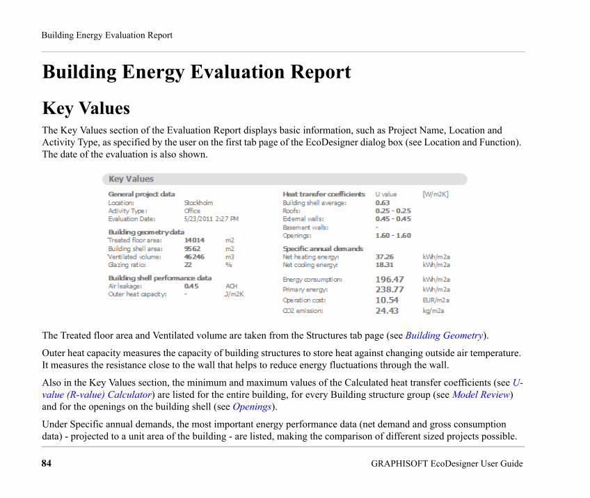
Building Energy Evaluation Report
Building Energy Evaluation Report
Key ValuesThe Key Values section of the Evaluation Report displays basic information, such as Project Name, Location and Activity Type, as specified by the user on the first tab page of the EcoDesigner dialog box (see Location and Function). The date of the evaluation is also shown.
The Treated floor area and Ventilated volume are taken from the Structures tab page (see Building Geometry).
Outer heat capacity measures the capacity of building structures to store heat against changing outside air temperature. It measures the resistance close to the wall that helps to reduce energy fluctuations through the wall.
Also in the Key Values section, the minimum and maximum values of the Calculated heat transfer coefficients (see U-value (R-value) Calculator) are listed for the entire building, for every Building structure group (see Model Review) and for the openings on the building shell (see Openings).
Under Specific annual demands, the most important energy performance data (net demand and gross consumption data) - projected to a unit area of the building - are listed, making the comparison of different sized projects possible.
84 GRAPHISOFT EcoDesigner User Guide

Building Energy Evaluation Report
Energy Consumption by SourcesThis section of the Evaluation Report contains one table and three pie charts.
The table’s leftmost column lists energy Sources by type (Renewable, Fossil and Secondary) and name, plus their color codes used in the pie chart. The Quantity column lists the magnitude [e.g. kWh/a] while the Cost column shows the price [currency/a] of each energy source consumed in one year.
The table’s rightmost column shows the carbon footprints associated with the listed energy source magnitudes.
GRAPHISOFT EcoDesigner User Guide 85

Building Energy Evaluation Report
The Distribution by Sources pie charts graphically display the percentage distributions of the
• quantities
• costs
• carbon footprints
of the used energy sources. The internal indicator ring shows the energy source type distribution while the external ring displays the actual energy source distribution.
86 GRAPHISOFT EcoDesigner User Guide

Building Energy Evaluation Report
Energy SourcesIn the table below, the energy sources used by EcoDesigner are listed according to their type and with their colors as displayed on the Energy Balance Evaluation report.
GRAPHISOFT EcoDesigner User Guide 87

Building Energy Evaluation Report
Carbon FootprintBesides the information on the carbon dioxide emissions resulting from the building’s operation over the course of a year, the magnitude of equivalent CO2 absorbent vegetation is also displayed on the Energy Balance Evaluation, under the CO2 Emission by Energy Sources pie chart.
EcoDesigner selects the display unit from three options automatically, according to project magnitude:
Note: 1 football field = 21 tennis courts
The CO2 emission factors assigned to the energy sources differ according to building location (see Location and Function). Use the Energy Source Factors dialog to enter the region-specific data if available, or evaluate the project using the default assignments offered by EcoDesigner (based on standard DINV-18599).
Magnitude of equivalent CO2 absorbent vegetation area (VA)
Unit of equivalent CO2 absorbent vegetation displayed
VA > 0,5 football field Football field of tropical forest0,5 football field > VA > 0,5 tennis court Tennis court of tropical forest0,5 tennis court > VA Developed pine tree
88 GRAPHISOFT EcoDesigner User Guide
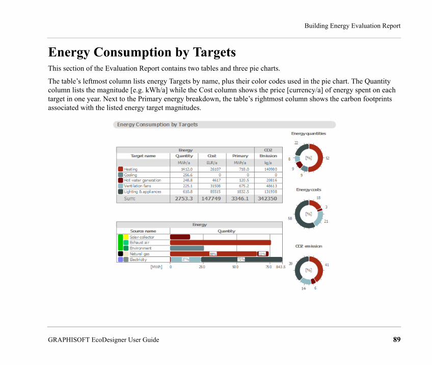
Building Energy Evaluation Report
Energy Consumption by TargetsThis section of the Evaluation Report contains two tables and three pie charts.
The table’s leftmost column lists energy Targets by name, plus their color codes used in the pie chart. The Quantity column lists the magnitude [e.g. kWh/a] while the Cost column shows the price [currency/a] of energy spent on each target in one year. Next to the Primary energy breakdown, the table’s rightmost column shows the carbon footprints associated with the listed energy target magnitudes.
GRAPHISOFT EcoDesigner User Guide 89

Building Energy Evaluation Report
The Distribution by Targets pie charts graphically display the percentages of the
• quantities
• costs
• carbon footprints
associated with each energy target.
The Target Quantities by Energy Sources bar chart links the information found on the Energy Consumption by Sources and on the Energy Consumption by Targets tables together, by displaying the energy target type, magnitude and percentage of each energy source.
Primary EnergyThe primary energy value is the ‘common denominator’ among different energy source consumption types, when determining the building’s total energy consumption. Not only does it indicate the net energy source consumed, but it also incorporates the energy needed for the manufacturing, transportation and the raw material processing of the energy source, as well as its transportation to the place of use. Minimizing the specific primary energy demand is a great way to improve the designed buildings’ overall performance.
The primary energy factors assigned to the energy sources differ according to building location (see Location and Function). Use the Energy Source Factors dialog to enter the region-specific data if available, or evaluate the project using the default assignments offered by EcoDesigner (based on standard DINV-18599).
90 GRAPHISOFT EcoDesigner User Guide
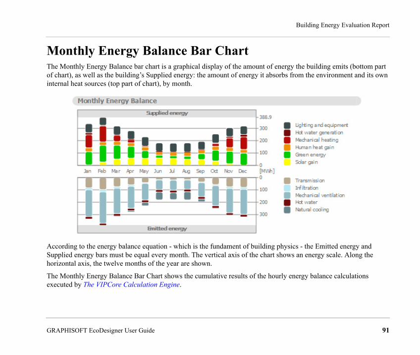
Building Energy Evaluation Report
Monthly Energy Balance Bar ChartThe Monthly Energy Balance bar chart is a graphical display of the amount of energy the building emits (bottom part of chart), as well as the building’s Supplied energy: the amount of energy it absorbs from the environment and its own internal heat sources (top part of chart), by month.
According to the energy balance equation - which is the fundament of building physics - the Emitted energy and Supplied energy bars must be equal every month. The vertical axis of the chart shows an energy scale. Along the horizontal axis, the twelve months of the year are shown.
The Monthly Energy Balance Bar Chart shows the cumulative results of the hourly energy balance calculations executed by The VIPCore Calculation Engine.
GRAPHISOFT EcoDesigner User Guide 91

Building Energy Evaluation Report
Energy Supply and Emission TypesTo the right of the Monthly Energy Balance diagram, the energy flows that make up the bars of the chart are listed. The number and type of these energy balance components that appear on a particular Energy Evaluation Report depend on the settings on the evaluated building’s MEP Systems and Energy and Green Energy tab pages.
The table below lists all energy supply and emission types with their Monthly Energy Balance bar chart display color.
These energy supply and emission categories, besides being used to visualize the energy balance, also provide addition information on the MEP systems (cooling, heating, ventilation type) and green energy solutions of the evaluated project.
92 GRAPHISOFT EcoDesigner User Guide

Building Energy Evaluation Report
The left column shows the energy flows that appear on the Emitted energy side of the energy balance bar chart, while in the right column the Supplied energy types are listed. The column in the middle contains energy flows that may appear as either emitted or supplied, depending on the particular situation.
Energy flows that are framed with solid lines in the table above require the input of one or more Energy Sources.
Natural Energy CurrentsThe energies that trigger the Natural energy currents (their names are framed with dashed lines in the Energy Supply and Emission Types table) are the result of sufficient external conditions:
• hot-enough external air temperatures in times of heating demand
• cold-enough external air temperatures in times of cooling demand
• sufficient placement and sizing of openings with proper opening/closing operation that enable natural ventilation
Customizing the Appearance of the Energy Balance Evaluation SheetThe graphical parameters of the Energy Balance Evaluation sheet are defined by the lines entitled Drawing Generator of the DefaultValues.xml file (see localized EcoDesigner contents).
<DefaultValue Name="DrawingGenerator.gNormalTextColor.Green" Value="103" />
<DefaultValue Name="DrawingGenerator.gNormalTextColor.Blue" Value="56" />
<DefaultValue Name="DrawingGenerator.gCaptionTextColor.Red" Value="0" />
<DefaultValue Name="DrawingGenerator.gCaptionTextColor.Green" Value="103" />
Excerpt from .xml file describing the appearance of the Evaluation sheet
It is not possible for the users to change the content of the evaluation sheet. Its appearance, however, may be customized.
GRAPHISOFT EcoDesigner User Guide 93

Building Energy Evaluation Report
It is recommended that the following parameters remain unchanged:
• Page borders
• Font sizes
• Spaces
• Column widths
• Chart sizes
• Carbon footprint image size
Parameters that may be changed to customize the appearance of the report sheet:
• Pen widths
• Background colors
• Text colors
• Border colors
• Energy group colors
• Energy source colors
• Bar chart background colors
• Pie chart colors
• Font name (type)
94 GRAPHISOFT EcoDesigner User Guide

Building Energy Evaluation Report
Function Buttons of the Evaluation Report At the bottom of the Evaluation Report:
• Back to EcoDesigner… takes you back to the EcoDesigner dialog box, allowing you to further adjust the building data.
• The Close button exits EcoDesigner without saving the Evaluation Report.
• Save as PDF lets you specify a location to which to save the Evaluation Report in PDF format.
• Click the button with the triangle in the bottom right corner to save the detailed monthly energy balance data in Microsoft Excel file format (see below).
GRAPHISOFT EcoDesigner User Guide 95
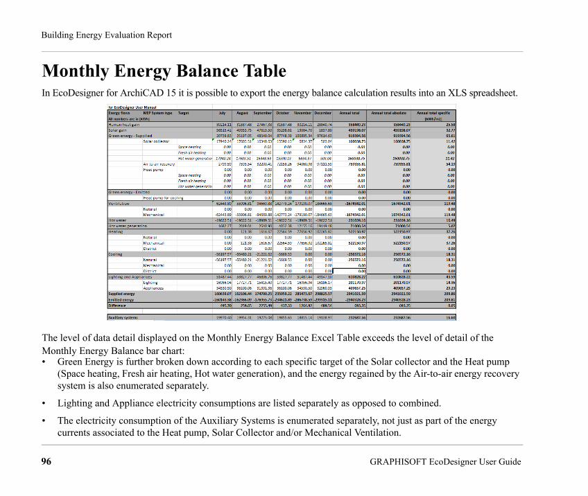
Building Energy Evaluation Report
Monthly Energy Balance TableIn EcoDesigner for ArchiCAD 15 it is possible to export the energy balance calculation results into an XLS spreadsheet.
The level of data detail displayed on the Monthly Energy Balance Excel Table exceeds the level of detail of the Monthly Energy Balance bar chart:• Green Energy is further broken down according to each specific target of the Solar collector and the Heat pump
(Space heating, Fresh air heating, Hot water generation), and the energy regained by the Air-to-air energy recovery system is also enumerated separately.
• Lighting and Appliance electricity consumptions are listed separately as opposed to combined.
• The electricity consumption of the Auxiliary Systems is enumerated separately, not just as part of the energy currents associated to the Heat pump, Solar Collector and/or Mechanical Ventilation.
96 GRAPHISOFT EcoDesigner User Guide


