Page 1
GRASP/Ada
Graphical Representations of Algorithms, Structures, and Processes for Ada
The Development of aProgram Analysis Environment for Ada
Reverse Engineering Tools For Ada
Task 2, Phase 2 Report
Contract Number NASA-NCC8-14
Department of Computer Science and Engineering
Auburn University, AL 36849-5347
Contact: James H. Cross II, Ph.D.
Principal Investigator
(205) 844-4330
August 1990
https://ntrs.nasa.gov/search.jsp?R=19910003770 2018-05-29T07:08:42+00:00Z
Page 2
ACKNOWLEDGEMENTS
We appreciate the assistance provided by NASA personnel, especially Mr. Keith
Shackelford whose guidance has been of great value. Portions of this report were
contributed by each of the members of the project team. The following is an
alphabetical listing of the project team members.
Faculty Investigator:
Dr. James H. Cross II, Principal Investigator
Graduate Research Assistants:
Richard A. Davis
Charles H. May
Kelly I. Morrison
Timothy PlunkettDarren Tola
-The following trademarks are referenced in the text of this report.
001, FMap, TMap are trademarks of Hamilton Technologies, Inc.
Ada is a trademark of the United Stated Government, Ada Joint Program Office.
AdaGRAPH is a trademark of George W. Cherry.
IORL is a trademark of Teledyne-Brown Engineering.
NEXT is a trademark of NEXT, Inc.
PAMELA is a trademark of The Analytical Sciences Corporation.
Rational is a trademark of Rational, Inc.
UNIX is a trademark of AT&T.
VAX and VMS are trademarks of Digital Equipment Corporation.
VERDIX and VADS are trademarks of Verdix Corporation.
PAMELA and AdaGRAPH are trademarks of Analytic Sciences Corporation.
PostScript is a trademark of Adobe Systems, Inc.
Page 3
TABLE OF CONTENTS
1.0 INTRODUCTION .......................................... 1
1.1 Algorithmic Diagrams (PDL/Code) ......................... 21.2 Architectural Chaits and Diagrams ......................... 4
2.0 ARCHITECTURAL DIAGRAMS IN CURRENT USE ............... 8
2.1 Definitions ......................................... 8
2.2 Graphical Representations for Architecture ................. 9
2.2.1 Common Architectural Diagrams .................... 9
2.2.2 Extraction of Architectural Diagrams from Source Code .. 18
2.3 Architectural Diagrams for Ada ......................... 19
2.3.1 Architectural Components of Ada .................. 20
2.3.2 Special Issues ................................ 21
2.4 Visual Computing Trends ............................. 23
3.0 STATEMENT OF THE PROBLEM ............................ 27
3.1 Overview ......................................... 27
3.2 Introduction of Taxonomy ............................. 27 :
3.3 Derivation of Base Set of Architectural Diagrams ............ 30
- 3.3.1 Level 1 Architectural Diagram ..................... 30
3.3.2 Level 2 Architectural Diagram ..................... 36
3.3.3 Level 3 Architectural Diagram ..................... 39
4.0 REQUIREMENTS AND PROTOTYPE IMPLEMENTATION ........ 42
4.1 Functional Requirements .............................. 43
4.1.1 Input Requirements ............................ 43
4.1.2 Processing Requirements ......................... 44
4.1.3 Display Requirements ........................... 45
4.1.4 Output Requirements .......................... 46
4.2 User Interface Requirements .......................... 48
4.2.1 Development Tool/Environment .................... 48
4.2.2 The User ................................... 49
4.2.3 Design Method ................................ 50
4.2.4 Design Goals ................................. 50
4.2.5 Design Decisions/Implementation ................... 51
4.2.6 Porting Phase 1 Components to X Windows ........... 52
4.3 Hardware Requirements .............................. 59
4.4 System Software Requirements ......................... 59
4.4.1 DIANA - An Intermediate Representation for Ada ...... 60
4.4.2 Library Management ............................ 66
4.4.3 Graphics Tools Requirements ..................... 67
4.5 Status of the GRASP/Ada Prototype ..................... 68
Page 4
5.0 FUTURE WORK ......................................... 705.1 ResearchApproach ................................. 705.2 ProposedResearchSchedule ........................... 72
BIBLIOGRAPHY ............................................. 74
APPENDIX A
"ReverseEngineering and Design Recovery : A Taxonomy" by E. Chikofsky andJ. Cross
APPENDIX B
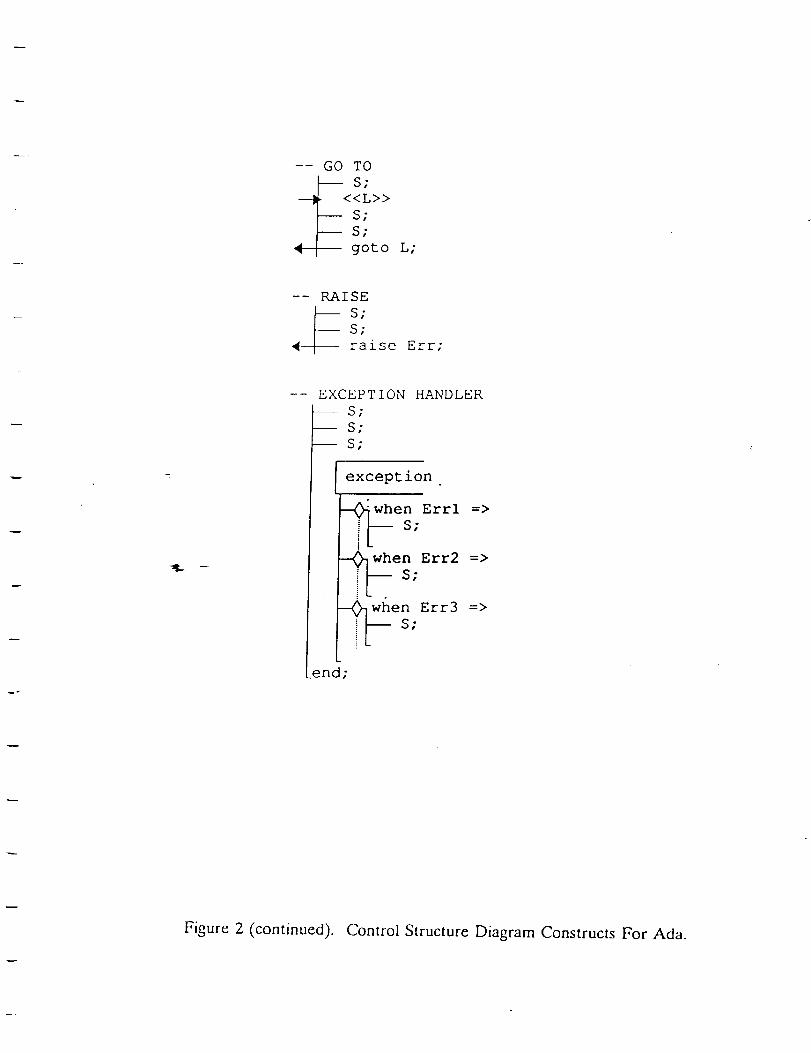
"Control Structure Diagrams For Ada" by J. Cross, S. Sheppard, and H. Carlisle
Page 5
LIST OF FIGURES
Figure
Figure
Figure
Figure
Figure
Figure
Figure
Figure
Figure
Figure
Figure
Figure
Figure
Figure
Figure
Figure
Figure
Figure
Figure
1. GRASP/Ada Overview ................................... 3
2. Structure Chart ....................................... 10
3. Buhr Chart .......................................... 12
4. Example of an Information Cluster in OOSD ................. 13
5. Example of a Schematic Block Diagram (SBD) in IORL ......... 16
6. Examples of Booch Diagram Components .................... 17
7. Taxonomy of Architectural Graphical Representions ............ 28
8. Ada Source Code For Procedure Solve ...................... 31
9. Architectural CSD With Conditions ........................ 32
10. Architectural CSD Without Conditions ..................... 33
11. Tentative Graphical Constructs for Level 2 .................. 37
12. Example Using Level 2 Constructs ........................ 40
13. GRASP/Ada Extended Character Set ...................... 47
14. GRASP/Ada System Window ........................... 53
15. GRASP/Ada Source Code Window ........................ 54
16. GRASP/Ada Control Structure Diagram Window .............. 55
17. Example of DIANA Subnet ............................. 61
18. GRASP/Ada System Architecture ..................... .... 69
19. Phase 3 Gantt Chart .................................. 73
Page 6
1.0 INTRODUCTION
Computer professionals have long promoted the idea that graphical
representations of software are extremely useful as comprehension aids when used to
supplement textual descriptions and specifications of software, especially for large
complex systems. The general goal of this research is the study and formulation and
generation of graphical representations of algorithms, structures, and processes for Ada
(GRASP/Aria). The present task, in which we describe and categorize various graphical
representations that can be extracted or generated from source code, is focused on
reverse engineering.
Reverse engineering normally includes the processing of source code to extract
higher levels of abstraction for both data and processes. Our primary motivation for
reverse engineering is increased support for software reusability and software
maintenance, both of which should be greatly facilitated by automatically generating a
set of "formalized diagrams" to supplement the source code and other forms of existing
documentation. The overall goal of the GRASP/Ada project is to provide the
foundation for a CASE (computer-aided software engineering) environment in which
reverse engineering and forward engineering (development) are tightly coupled. In this
environment, the user may specify the software in a graphically-oriented language and
then automatically generate the corresponding Aria code [ADA83]. Alternatively, the
user may specify the software in Ada or Ada/PDL and then automatically generate the
graphical representations either dynamically as the code is entered or as a form of post-
1
Page 7
processing. Appendix A contains a comprehensive taxonomy of reverse engineering,
including definitions of terms.
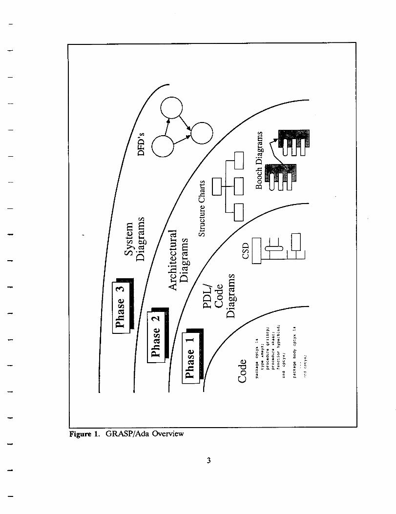
Figure 1 shows the project divided into three phases, each of which corresponds
to one of the following broad categories of graphical representations: (1) algorithmic
(PDL/Code), (2) architectural, and (3) system level diagrams. Each of these categories
may contain overlapping entries that depict, for example, data structure, data flow, or
other useful relationships. Phase 1 of GRASP/Ada has been completed and a new
graphical notation, the Control Structure Diagram (CSD) for Ada and supporting
software tool is now being prepared for evaluation [CRO88, CRO89]. In Phase 2, the
focus is on a subset of Architectural Diagrams that can be generated automatically from
source code with the CSD included for completeness. These are described briefly in the
order that they might be generated in a typical reverse engineering scenario. Phase 3
is described briefly in the final section of this report, entitled "Future Work."
1.1 Algorithmic Diagrams (PDL/Code)
As the complexity of software has increased, so has the utility of graphical
representations for algorithms. The industry has progressed well beyond the simple
constructs of sequence, selection and iteration promoted by the theory of structured
programming in the 1970's. For example, Ada includes control constructs for
concurrency (tasks and task rendezvous), exception handling, and loop exits, none of
which fits well into the simple sequential control constructs of structured programming.
Since the ANSI flowchart was introduced in the mid-50's, numerous notations have been
proposed and utilized [MAR85, TRI89]. These notations typically include control
2
Page 8
Figure 1. GRASP/Ada Overview
Page 9
constructs for sequence, selection, and iteration, and several include constructs for
concurrency and exits; however, none explicitly contains all of the control constructs
found in Ada.
For the GRASP/Ada project, the Control Structure Diagram was selected as a
basis for a graphical representation that maps directly to Ada control constructs. The
CSD is a graphical notation intended to increase the comprehensibility of Ada PDL or
source code by explicitly depicting control constructs and control flow. The traditional
textual representation of PDL or source code has been extended with intuitive graphical
constructs which are easily adaptable to editors and printers. The CSD has the
attractive property that it has the appearance of being overlaid directly on prettyprinted
Ada code. In fact, a CSD generator may be perceived as a "graphical prettyprinter."
Appendix B contains a paper, entitled "Control Structure Diagrams For Ada," which
describes and illustrates the CSD graphical constructs.
1.2 Architectural Charts and Diagrams
The next level of diagrams in the reverse engineering process is a group
commonly known as architectural diagrams. Structure charts, data structure diagrams,
and entity-relationship diagrams are traditional examples of these. The object/package
diagram is a relatively recent addition at this level. Structure charts, object/package
diagrams, and a collapsed version of the control structure diagram have been targeted
for prototyping in Phase 2. Structure charts and object/package are each discussed
briefly below in the context of automatically generating the diagram from source code
or PDL. Structure charts are one of the oldest and potentially most useful diagramming
4
Page 10
notations available. We use the term here in the generic senseto refer to those charts
and diagrams that depict the overall hierarchical organization of a software system
without concern for the algorithmic details. In this sense,the structure chart is simply
an invocation graph of functions and procedures in which redundant calls are omitted.
IBM's HIPO, and Yourdon's structure chart are common examples in this category.
Someversions indicate data items along the control lines between procedures to show
data flow as well as limited detailed control flow information such as selection and
iteration.
The structure chart offers the user a high-level solution-oriented view of the
software. Although algorithmic details are suppressed, the user can still get a sense of
what is going on from the perspective of solving the problem as well as a feel for the
layers of procedures and functions involved. Unfortunately, structure charts generated
during initial development of a system are rarely kept current without the aid of a
CASE tool which links the diagram and corresponding code. A major role of reverse
engineering in a CASE environment is to ensure the availability of an accurate set of
structure charts as well as graphical representations for other software views such as
algorithmic and data flow.
Automatic generation of structure charts from source code is relatively
straightforward. In the case of Ada, the abstract syntax tree built during the parse must
be traversed, capturing procedure and function calls (a task rendezvous has the
appearance of a procedure call). A call to a procedure or function results in the
traversal of its abstract syntax tree. Redundant calls from a single procedure are
normally captured but not displayed. Data items and their direction of flow are
O
Page 11
identified syntactically by their IN, OUT, or INOUT designation in the parameter list.
Additional program analysis is required to determine references to non-local variables
that are not formal parameters.
The Object�package diagram made popular by Booch is a recent architectural
level diagram that is useful for object-oriented software [BOO83, BOO86, BOO87a,
BOO87b]. The object/package diagram shows all of the dependencies among packages
and package components. This is an important view of the software with respect to its
construction or composition from parts. For example, an Ada package may be used for
encapsulation of types and operations to form abstract data types. These packages can
then be considered objects from an object-oriented development perspective.
Object/package diagrams are generated from a syntactical analysis of the Ada
source code. The basic dependencies are defined by the WITH clause. The actual
package components that are utilized are determined by references to types, procedures
and/or functions exported by the package. These objects or packages can be further
graphically encoded by using icons, shading, and coloring.
Preliminary analysis has revealed that structure charts and object/package
diagrams are complementary in nature and, furthermore, that in isolation each affords
a somewhat incomplete view of the software. The hierarchical or layered structure
chart is easily related to the software solution of the problem. That is, a reader can
discern "what" is being done with respect to solving the problem or, from a reverse
engineering perspective, which problem is being solved. The object/package diagram,
on the other hand, offers a view of component packaging (e.g., how data and
operations are packaged into objects). While Booch points out that the object/package
6
Page 12
diagram is much closer to the data flow diagram of the general specification of the
problem (e.g., external entities and data stores become objects)flit has been our
experience that the dependencies shown in the object/package diagram provide little or
no information regarding the interaction of the objects and operations. The structure
chart and ultimately the control structure diagram do supply the additional information
necessary for complete comprehension of the solution.
The remainder of this report is organized as follows. Section 2 discusses
architectural diagrams that are currently in use, a brief review of efforts to extract
architectural diagrams from source code and provides a summary of several general
trends in visualizations in computing. Section 3 provides a discussion of the problem
Phase 2 of the GRASP/Ada project is addressing. Section 4 provides a statement of
requirements and a description of the prototype that is currently being developed to
support the automatic generation graphical representations from Ada source code.
These requirements include functional, interface, hardware, and system software.
Section 5 provides an overview of Phase 3 of GRASP/Ada.
7
Page 13
2.0 ARCHITECTURAL DIAGRAMS IN CURRENT USE
In this section, the term "architectural diagram" and other related terms are
defined. This is followed by a brief survey of recent as well as traditional architectural
diagrams which have been used for Ada. The specific needs for architectural diagrams
for Ada software are examined. This section concludes with a brief discussion of trends
in visualization for computing in general.
2.1 Definitions
An architectural diagram (AD) may be defined as follows: a graphical
representation of the logical components of a software system, the interfaces between
such components, and the hierarchical relationship among the components.
Logical components of a software system are those structures which group
statements and components into cohesive units. In Ada, these structures include the
package, procedure, function, and task. Most well-designed logical components are
functionally cohesive, each providing a single and specific service.
The interfaces between the logical components of a software system show the
invocation convention for communicating between components, including any parameters
which are passed. Although in the simplest case there may be no parameters passed
between a given set of components, usually parameters consist of items of complex types
and, in the case of Ada, may even include tasks.
8
Page 14
The hierarchical relationship among the logical components of a software system
is shown as a utilization hierarchy. A _'onnection between any two components
represents a resource usage of one component by the other.
Two other terms that are of use when referring to hierarchical diagrams are
visibility and connectivity. Each is a term referring to the scope of a given software
component. Visibility refers to the set of components that may be invoked by a given
component, regardless of whether the code actually specifies an invocation of such
components. Connectivity refers to the set of components that are explicitly invoked
by a given software component in the source program.
2.2 Graphical Representations for Architecture
In this section, several architectural diagrams currently in use are briefly
discussed. This is followed by a brief review of representative efforts to extract
architectural diagrams and related information from source code.
2.2.1 Common Architectural Diagrams
Perhaps the best-known architectural diagram is the traditional structure chart
made popular by Yourdon and Constantine (see Figure 2). This diagram represents the
architecture of a system using a set of boxes representing functions and procedures
connected by lines indicating invocation. Small arrows are arranged along the lines of
invocation to depict the flow of data between the modules. Typically, data flows are of
two types: "pure" data items, which may be either simple or complex data types, and
control data items, which are used to determine the execution of the invoked procedure.
9
Page 15
Control/DataLinks
Controldataflow
Dataflow
Modules
Figure 2. Structure Chart
10
Page 16
Although the traditional structure chart is useful for depicting the architecture of
systemswritten in s_mplelanguagessuchas Pascal,it lacks in the capability to represent
advancedfeatures found in Ada suchastasking and generic instantiation of procedures
from templates.
CAEDE (Carleton Embedded SystemDesign Environment) is a software CAD
system developed at Carleton University by Buhr [BUH89] that uses modified Buhr
diagrams to represent the architecture of an Ada program (see Figure 3). The
structural CAEDE diagrams are block-oriented and include distinct symbols for tasks,
packages, and procedures. Although the CAEDE system does include graphical
representations for all of the Ada architectural components, it does not represent
generics well. In addition, the nesting required to produce an accurate CAEDE
diagram for a typical Ada program can become cumbersome. At this time, there is no
existing tool for generating CAEDE diagrams from existing code.
OOSD (Object-Oriented Structured Design), developed by Wasserman [WAS89],
is a method for designing the architecture of systems. The heart of OOSD is the OOSD
design chart, a modified structure chart, that describes a set of architectural components,
their invocation hierarchy, and the parameters passed among them (see Figure 4). At
a lower level, information clusters provide an object-oriented description of the
components depicted on the design chart. Because OOSD is designed to be language-
independent, it does not correspond exactly to Ada, and therefore does not directly
support all Ada features, especially the tasking constructs. On the other hand, OOSD
does allow the designer to utilize some features that Ada does not provide. At this
time, there is no existing tool for generating OOSD diagrams from existing code.
11
Page 17
user
sta[us _
reserve ]
cancela,k
request _
cancel I J ask
agent_pool
Figure 3. Buhr Chart
12
Page 18
O
ParseExpression
_______ push]
<_ stack
item
I
pop_ ]_]
(stacktp)-_ ---j
evalstak
Figure 4. Example of an Information Cluster in OOSD
13
Page 19
Hamilton Technologies,Inc., hasdevelopedan integrated hierarchical, functional
and object-oriented modeling approach collectively called 001 technology. The 001
technology is based, in part, on USE.IT developedby Higher Order Software (HOS)
[HAM79]. In 001,a systemis defined in terms of a singlecontrol map which integrates
both function control maps (FMaps) and type control maps (TMaps), where an FMap
defines a hierarchy of functions and a TMap defines a hierarchy of abstract types. The
underlying specification language for these maps is 001 AXES, which is based on a set
of control axioms derived from empirical data gathered during the development and
operation of the existence of a universal set of objects. The leaves of the maps
represent primitives implemented in a language for a particular native computer
environment. When a system specified in 001 AXES is processed by the "Resource
Allocation Tool," the result is a complete system in the source language of the
primitives.
I_AMELA (Process Abstraction Method for Embedded Large Applications) is a
methodology developed by
environment on the IBM PC.
Cherry [CHE86] and supported by the AdaGRAPH
A specification is written in PAMELA by first describing
a system as a collection of flow diagrams. Next, the analyst is prompted to answer
certain questions about each of the processes in the flow diagrams, resulting in
corresponding annotations to the diagrams. Finally, the analyst completes the skeleton
code generated from the flow diagrams by filling in the algorithmic details which can not
be generated from the diagrams. It is interesting to note that the "automatic code
generation" provided by PAMELA falls mainly into the area of providing correctly
specified modules and communications between these modules. Generating procedural
14
Page 20
code is left to the analyst, although the AdaGRAPH environment does provide facilities
for simplifying this.
IORL (Input�Output Requirements Language) is a high-level requirements
language developed for the design of real-time embedded systems with the TAGS
(Technology for the Automated Generation of Systems) methodology [SIE85]. TAGS
embodies the hierarchical top-down development of a system, and relies upon graphical
representations to present control flow within a process and data flow among different
processes executing simultaneously (see Figure 5). A system may be viewed at any time
from a number of levels: from a very high level showing an overview of the entire
system, from a very low level showing the IORL primitives that make up a process, or
from any level in between. The latest release of IORL utilizes an icon-oriented
interface for the easy creation of IORL diagrams. Currently, Teledyne Brown
Engineering is working on a "Simulation Compiler" which will significantly enhance the
TAGS development environment by facilitating simulated execution of the IORL
specification.
Booch diagrams [BOO83] provide a graphical representation of the architectural
components of Ada along with some dependency information (see Figure 6).
Experience indicates that the graphical representation of large systems using Booch
diagrams often leads to a network decomposition rather than a strict hierarchical control
organization. In addition, at the present time, only primitive tools exist for the
extraction of Booch diagrams from Ada source code.
15
Page 21
1
OPERATOR
Mill Operator
ALCOASYS-1
...ALCOASYS-2
ALCOASYS-4
2
CONTROL
Rolling MillControl
3
MILL
Rolling Mill
ALCOASYS-3
Figure 5. Example of a Schematic Block Diagram (SBD) in IORL
16
Page 22
Program component
Specificationpart
Operation
Undefineddetail
Package body
Figure 6. Examples of Booch Diagram Components
17
Page 23
2.2.2 Extraction of Architectural Diagrams from Source Code
Numerous efforts to generate architectural diagrams and related information can
be found in the literature. Most CASE tool vendors (e.g., those cited in the previous
section) are attempting to develop reverse engineering capabilities which will enable the
user to redocument existing software using their systems. Several other research efforts
which are representative of those currently underway are briefly described below.
Choi and Scacchi at the University of South California have developed a module
interconnection language called NuMIL from which hierarchical diagrams may be
extracted [CHO90]. A NuMIL description of the source code is generated, and this
description is analyzed in terms of resource flow among the various modules in the
system, where resources include data types, procedures, and variables. Application of
a restructuring algorithm then provides a hierarchical description of the system. It is
interesting to note that the USC approach tends to focus on the extraction of the
structm:al design and not its presentation. The graphical representation of the extracted
information has not been addressed.
ARCH is a system developed by Schwanke et. al. of Siemens Corporate
Research, Inc., to extract and display the structure of C programs [SCH89]. It uses a
many-to-one mapping from the target program to a structure chart to abstract a large
system into a form that may be easier to understand. The basis of the mapping is the
data used by the various procedures in the target program: modules which operate on
common data are assumed to be related and are grouped in subsystems. As with the
NuMIL project at USC, the ARCH project has tended to focus more on the extraction
and not the presentation of a system's structure.
18
Page 24
DESIRE is a prototype of a design recovery tool developed by Biggerstaff of the
Microelectronics and Computer Technology Corporation that analyzes a C program and
produces a web that displays the relationships between the program's data and modules
[BIG89]. The web is presented using a hypertext system, and the program structure is
represented by links among the module names. The web is not hierarchical and does
not make use of any graphical representations, nor does it depict the data flow passed
between modules.
PathMap is an analysis tool developed by O'Brien of the Microcase Division of
Cadre Technologies that works with Cadre's Teamwork/SD to produce annotated
Constantine structure charts with information about the target program's runtime
performance [OBR89]. The runtime data includes a count of the number of times the
program was invoked and the percentage of CPU time it consumed. These items are
represented in much the same way on the structure chart as parameters that are passed
among l_odules. Other than this, PathMap provides no other graphical extensions or
modifications to the Constantine structure chart.
2.3 Architectural Diagrams for Ada
Components of the Ada programming language that must be considered when
developing architectural diagrams are examined below. This is followed by a discussion
of special issues pertaining to the Ada programming language that must be considered
during the development of any practical architectural diagram for Ada.
19
Page 25
2.3.1 Architectural Components of Ada
Most high level programming languages have very few architectural components.
For example, Pascal has only procedures, functions, and a single main program.
However, Ada is much more complex, with constructs that are difficult to represent
using traditional architectural diagrams. In this section, the architectural components
of the Ada programming language are examined.
The architectural components of Ada may be subdivided into two categories:
logical and physical. The logical components are those structures defined within the
language that serve to group sets of logically related statements or componen!s. The
physical components are those components which serve more to assist the Ada compiler
rather than the Ada programmer.
There are five logical components in the Ada programming language: packages,
procedures, functions, tasks, and operators. Packages are structures which serve to
group ti_e other logical components into cohesive modules. Procedures, functions, and
tasks are much alike in that they are small threads of executable code that generally
provide a single specific service. Operators may be considered a special case of function
that may take one or two arguments. Although operators are predefined in most
programming languages, Ada allows them to be overloaded.
There are three physical components in the Ada programming language: library
units, secondary units, and subunits. A library unit is a specification that defines a set
of logical components and data declarations. A secondary unit is the body of code that
implements each of the logical components defined in the corresponding library unit.
20
Page 26
Finally, a subunit is a section of code that implements a logical component defined in
a library unit but may be compiled separately.
In addition, the logical components may have properties associated with them.
For example, a logical component may be a standard component, with all its data types
explicitly defined. Or, it may be a generic component that may be instantiated for a
given data type. Another property that logical components in Ada exhibit is that of
visibility. A logical component may be visible, and accessible to any other component
that refers to it, or it may be hidden, only accessible by other components in its
package.
2.3.2 Special Issues
In this section, _some of the special issues which must be addressed in the
development of a set of architectural diagrams for Ada are discussed.
Representation of generics. The generic construct in the Ada language allows the
definition of "templates" for software functions which describe a function's logic without
making any commitments to data types. The generics may be easily instantiated to
operate on any set of data types. In an architectural diagram, these functions would
appear in many places as distinct functions, although they differ only in the data types
on which they operate. Some method for capturing this similarity in the architectural
diagram should be developed.
Representation of overloading. Ada allows a number of simple operators to be
"overloaded." This is similar in respect to the notion of generic functions in that the
only difference between functions is the set of data types on which they operate.
21
Page 27
Representation
invocation
execution.
graphical depiction has not been well investigated.
Representation of "static" vs. "dynamic" scope.
of tasking. Architectural diagrams generally represent the
hierarchy among a set of procedures for a single thread of program
Ada introduces the concept of tasking, or simultaneous execution, whose
In most high level languages, all of
the components of a software system "exist" for the duration of the system's execution;
this may be referred to as "static" scope. In Ada, however, components may exist only
for portions of the system's lifetime, due to tasking and to the ability to embed
components inside others; this may be referred to as "dynamic" scope. Some method
for representing these on an architectural diagram must be developed.
Representation of scope of private functions and procedures. Ada allows packages
to have private functions and procedures which are visible only to other functions and
procedures in that package. There are no provisions for showing this in traditional
archite_ural diagrams.
Representation ofrecursion. Ada, like most other high level procedural languages,
supports both direct and indirect recursion. The simple methods for depicting this on
a structure chart, which have been used in conjunction with other languages, may suffice
until a representation more suitable for Ada is devised.
Representation of functions passed as parameters. Ada allows functions to be
passed as parameters in the instantiation of generics. Traditional architectural diagrams
have no means for showing components passed as parameters in an invocation.
Representation of embedded packages and tasks. Ada allows packages, procedures
and tasks to be declared anywhere in a program that variables and data types may be
22
O
Page 28
declared. As a result, procedures with a dynamic lifetime may be declared that are
callable by the component in which they are embedded but only for the scope of their
declaration. There is no convention for showing this on an architectural diagram.
Representation of physical components of software. Traditionally, architectural
diagrams show only the logical architecture of software and ignore the physical
architecture. The "packaging" of most large systems is critical to the success of the
system from both the developmental and maintenance perspectives.
Representation of architecture using layers. As the needs of software systems
become more and more complex, the size of such systems has grown dramatically, often
beyond the point where a single person could readily understand the inner workings of
the systems. To render these systems more presentable to the software engineer, it is
necessary to develop some method for layering the architecture of the system so that
it may be presented in successive degrees of abstraction.
_epresentation of all Ada-specific components. For an architectural diagram for
Ada to be practical, it must represent all of the architectural components of the Ada
programming language.
Representation of visibility and connectivity. To assist
programmer, visibility and connectivity must be represented on
diagram.
the maintenance
the architectural
2.4 Visual Computing Trends
In this section, current trends in visualization in computing are presented. While
much of the discussion focuses on visual programming, the ideas are relevant to all
23
Page 29
phases or levels of graphical representations. Although relatively new to the automation
environment, visual programming techniques provide an effective *as well as versatile
means to perform a wide spectrum of analysis and design functions. It has been
observed that the use of graphical representations to model, design, and evaluate
complex programming processes greatly enhances the ability of the user to understand
the process in question [SHU88, AMB89]. This concept of allowing a user to visualize
information in a form other than textual is being utilized in numerous areas. The
graphical representation of complex or enormous quantities of information is currently
being employed in the fields of data design, program design, program execution analysis,
software engineering, and visual programming languages.
The use of visual representations has evolved far beyond the simple mapping of
textual data to that of a graphical representation. In fact, new developments in the field
are leading to systems and environments that are graphically oriented by nature. Visual
user infe..rfaees modelled after a paradigm of overlapping windows, such as those found
in Smalltalk, provide multiple views of a common internal database. Whenever any
portion of the data is changed, all relevant views are updated to reflect that change.
Graphically oriented language environments include Pecan, Cedar, and Software through
Pictures [AMB89, FOR88].
Visual editing provides the user with the capability to modify existing programs
or produce new ones through the use of templates that correctly reflect the language's
syntax. Such current systems include the Cornell Program Synthesizer editor and the
Aloe editor used in Gandalf. Several other graphical editors enforce logical consistency
24
Page 30
through the addition of rules regarding the structure of a program. Higher Order
Software's Use.It and PegaSys are examples of systems that use this technique lAMB89].
The utilization of visual technology to edit programs written in traditional
languages has been joined by a new philosophy of programming paradigms under a
category referred to as "naturally visual languages" [AMB89]. Under these language
environments the basic language constructs are visual rather than textual. A variety of
approaches are used in such languages. The application of dataflow, constraints, form-
based and program-by-demonstration paradigms serve as the bases for environment
supported languages such as ThinkLab, ThinkPad, and Rehearsal World lAMB89].
Somewhere between the visual programming language and the textual languages
one finds Conic. This programming environment uses a combination of text and
graphics to define "configurations" that collectively make up a program [KRA89]. It
focuses on the functionality of processes, their control characteristics, and
commui_ication interaction.
Although much emphasis has been placed on the role visual programming plays
in user interfaces, editors, and programming languages, its potential far exceeds this
scope. As stated above, the use of graphical representations has showed itself to be
extremely useful in any area that inherently has large quantities of complex information.
Two such applications utilizing visual techniques as a means to better understand actual
events include performance debugging, specifically in regard to multiprocessor systems,
and concurrent computations [LEH89, ROM89].
Carnegie Mellon University has demonstrated the usefulness of visualization
through its special software development environment known as the Parallel
25
Page 31
Programming and Instrumentation Environment or PIE. This system is designed to
develop performance-efficient parallel andasequentialcomputationsby mapping parallel
applications onto specific architectures, gathering data as the applications execute and
producing graphical representations that reflect selected characteristics of the actual
execution [LEH89].
The visualization of concurrent computations employs visual abstraction by
"mapping from computational statesto the states of graphical objects" [ROM89]. This
approach hasbeen usedto insure the correctnessof a process,consistencyin execution
and .progressin the computation of a solution.
Visualization of programming hasbeen demonstrated to be an effective means
of representing complex processes,data structures, and computational events. The
primary element that makes each of the systemsexamined above viable is its well
defined utilization of graphical representationswithin the context of its application.
-g.. --
26
Page 32
3.0 STATEMENT OF THE PROBLEM
In this section, the overall direction for the GRASP/Ada Phase 2 prototype is
presented. First, the goals and objectives for the prototype are briefly discussed. Finally,
the tentative architectural diagrams for Ada are introduced.
3.1 Overview
In Phase 1 of the GRASP/Ada project, the focus was on the algorithmic
representation of Ada programs and the CSD (Control Structure Diagram) was
developed to graphically depict Ada control constructs. In Phase 2, the focus was shifted
to the structural (or architectural) view of Ada, and new diagrams must be developed
to represent this view. Although one diagram (the CSD) was sufficient to represent the
algorith_nic-;ciew of Ada, multiple diagrams are needed to adequately represent the
structural view of the software architecture.
3.2 Introduction of Taxonomy
To assist in the development of a layered approach to the graphical depiction of
Ada, a tentative taxonomy of graphical representations has been developed. This
taxonomy defines five distinct views of Ada software: the code view, the algorithmic view,
the connectivity view, the visibility view, and the logically related view (see Figure 7).
The code view is the base view of Ada software, consisting of the source code
itself. This code may be optionally augmented with some additional information such
27
Page 33
0
Visibility View
Connectivity View
Algorithmic View
Code View
Figure 7. Taxonomy of Architectural Graphical Representions
28
Page 34
V ¸
as line numbers, nesting data, and a cross-reference, but its low-level nature renders it
difficult for the software engineer to quickly comprehend the code.
The algorithmic view of Ada is intended to enhance the code view by graphically
representing control structures. The CSD developed in Phase 1 of the GRASP/Ada
project serves this purpose by augmenting Ada code with small iconic representations
of the various control structures. These graphics are embedded in the code in the area
normally used for "white space," and thus coexist with the code without requiring
significant spatial reorganization.
Phase 2 of the GRASP/Ada project is focused on the connectivity view and the
visibility view of Ada. The connectivity view shows the architectural components of an
Ada system with their invocation hierarchy and associated parameters. This view is
most like the traditional structure chart, yet has been enhanced and represented by two
distinct graphical representations in the GRASP/Ada system. The first is the Level 1
architectural diagram which consists of a "collapsed" CSD that shows the architectural
components and the control logic that leads to the statements that show each of the
components being invoked. The second graphical representation is the Level 2
architectural diagram that utilizes a traditional structure chart with appropriate
modifications and extensions for Ada.
The visibility view of Ada represents a set of architectural components and their
associated scopes, both static and dynamic. Whereas the connectivity view shows which
component are explicitly called (or invoked) by other components, the visibility view
shows which components may be invoked by other components. This view also denotes
29
Page 35
O
the dependency relations among Ada software components, and will be graphically
represented using modified Booch diagrams.
The logically related view of Ada will be the focus of the proposed Phase 3 of the
GRASP/Ada project. This view shows the data flow among logically related groups of
software architectural components, and may be considered an abstraction of the visibility
view. Although the proposed GRASP/Ada graphical representations for this view have
not yet been fully developed, they will include a set of modified data flow diagrams and
tasking diagrams.
3.3 Derivation of Base Set of Architectural Diagrams
In this section, the tentative base set of architectural diagrams for Phase 2 of the
GRASP/Ada project are described. There are three proposed graphical representations
for this phase: the Level 1 architectural diagram, the Level 2 architectural diagram, and
the Lex_'..l 3-architectural diagram.
3.3.1 Level 1 Architectural Diagram
The Level 1 architectural diagram bears a close resemblance to the CSD used
for representing algorithmic details. Figure 8 contains source code for procedure Solve
which uses package Stack_Package to calculate the result of an expression read in as
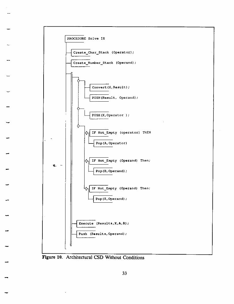
a character line. Figures 9 and 10 show two of several alternatives under consideration
for the Level 1 architectural diagram. This graphical representation is designed to
incorporate the features of the detailed level CSD as depicted in GRASP/Ada, and
those of the traditional structure chart to derive a diagram called the architectural CSD
30
Page 36
-- This program is designed to read a single line-- of character input and evaluate its value as a simple
-- equation.
-- An example input would be: ((I + 7)*((4 - I)*(3 * 8)))-- With a result of 432
WITH Text_IO, Stack_Package;
PROCEDURE Solve IS
PACKAGE Type_Integer_lO IS NEW Integer_IO (Integer);
PACKAGE Character_Literal_IO ISNEW Enumeration_IO (Character);
X,Y,Z : CHARACTER;Result,A,B : REAL;Operand : Number_Stack_Type;Operator : Char Stack Type;Input_File, Output_File : File_Type;
BEGIN
Open (Input_File, In_file, "Input_Expression In");Create (Output File, Out_File, "Results. Out" ;
Create_Character_Stack ( Operator );
Create_Number_Stack ( Operand );Get (Input_File, X);WHILE NOT End of line (Input_File) LOOP
CASE X ISWHEN '1';'2'1'3';'4';'6'1'7';'8';'9' '0' =>
Convert(X, Result);Push (Result, Operand);
WHEN '+'','-' ','*' =>
Push (X, Operator);WHEN ' ) ' = >
IF Not_Empty (Operator) THENPop (X, Operator);
END IF ;IF Not_Empty (Operand) Then
Pop (A, Operand);END IF;
IF Not Empty (Operand) Then
Pop (B, Operand);END IF;
WHEN OTHERS => NULL;END CASE ;
Execute (Result, X, A, B);Push (Result, Operand);
Get (Input_File, X);
END LOOP;
Put (Output_File, Results, O, IO);END Solve;
Figure 8. Ada Source Code For Procedure Solve
31
Page 37
PROCEDURE Solve IS
Create_Char_Stack (Operator);
Create_Number_Stack (Operand);
WHILE NOT End of File (Input_File) LOOP
CASE X I S
WHEN 'I'''2'''3'''4'''5_''6'''7'''9'''0''>___
[ Convert (X, Result) ;
_ PUSH(Result, Operand) ;
WHEN '+' I'-' I'*' I ">
i _ PUSH(X,Operator );
II
_I I; N0t_Empty (operator) THEN
I Pop(A,Operator)
F Not_Empty (Operand) Then;
Pop (B, Operand) ;
[ IS Not_Empty (operand)
Pop (Z, operand) ;
Then;
_ Execute (Results,X,A,B);
_ Push (Results,Operand);
Figure 9. Architectural CSD With Conditions
32
Page 38
PROCEDURE Solve IS
-- Create Char Stack (Operator);
Create_Number_Stack (Operand);
m
Convert (X, Result) ;
PUSH (Result, Operand) ;
i PUSH (X, Operator ) ;I
!i
_F Not_Empty (operator)
THEN
"PVp (A--_erat or)
F Not_Empty (Operand) Then;j , eran );
I IF Not_Empty (Operand) Then;
Pop (Z, Operand) ;
--_ Execute (Results,X,A,B);
--_ Push (Results,Operand) :
Figure 10. Architectural CSD Without Conditions
33
Page 39
or ArchCSD, which represents an intermediate level of abstraction. This collapsed
version of the CSD is expected to provide a compact visualization of the architectural
aspects of the software while preserving the essential control characteristics. Not only
will it show the architectural components which it includes, but it will also display the
invocations of these components, and the control logic leading to those invocations.
As stated earlier, the two graphical representations of particular interest to this
research are the traditional structure chart and the control structure diagram. The
structure chart was first made popular by Yourdon and Constantine. They represented
a system's basic architecture through the linking of boxes. Each box represents a
module such as a function or procedure. These diagrams were able to show data flow
to a limited extent. The structure chart does have limitations in that, in practice, it
generally does not attempt to address the details of control flow leading to invocation
of a module. Specific details regarding the sequence of processes, their conditional
selectio_ or the number of times they are called are not explicitly included
[PRE87,MAR85]. Although efforts have been made to represent this information
through structure charts augmented with additional symbology, such representations
have difficulty representing complex programs with procedural invocations that are
nested in sophisticated conditional constructs. In certain cases, the conditions leading
to a procedural invocation may itself involve multiple function calls.
More recent CASE tools have found that this type of representation is critical
in the forward design process. The developers of HIPO II (Hierarchy plus Input-
Process-Output), for example, realized the need for such information and incorporated
control flow directly into their hierarchy chart [ROE90]. Previous experiences with the
34
Page 40
original HIPO indicated that control information was critical to the user's ability to
communicatean overviewof the programsfunction. One of the observeddisadvantages
to the HIPO II implementation is its non-distinct symbology. Its main graphical
constructs are limited to single and double lines and two text symbols to represent
control flow. Although this may be adequate in forward design, more information is
needed in reverseengineering.
Ada.
This is particularly true with complex languages such as
The CSD, in contrast, uses a distinct graphical symbol for each major control
flow construct, and had ease of automation as a central design objective. The successful
implementation of the CSD tool for a large high-level language such as Ada tends to
support this claim regarding ease of automation.
Although the CSD was designed to depict control flow at all levels of program
abstraction, it is also suitable for use during detailed design as an extension to
pseudo_ode-or PDL. Designed with the primary purpose of reducing the time required
for program comprehension, it is a natural tool for reverse engineering [CRO88]. In
addition, it provides a sound basis for developing an architectural diagram which elides
much of the detail found in the CSD.
The Level 1 architectural diagram may be obtained using the same technique
utilized in the CSD generator developed in Phase 1 of the GRASP/Ada project.
Although the implementation of such a diagram presents some new problems with
respect to the traditional scan and parse approach to CSD prettyprinting, initial research
shows that the generation of such a graphical representation from source code is
35
Page 41
possible. In fact analysis indicates that the generation can occur with the time
complexity of O(N), where N is the number of statements in the source code.
It is important to note that this proposed tool is not designedto replace any of
the architectural representationscurrently in use. The ArchCSD is a supplemental view
of a program that depicts information that previously was omitted from traditional
architectural diagrams, implicitly included, or only obtainable at the source code level.
The availability of this diagram should aid implementation and maintenance
programmers to better understand the role of different modules within the a system.
With the ever increasingsizeand complexity of programs,the ArchCSD should provide
valuable insight.
3.3.2 Level 2 Architectural Diagram
The Level 2 architectural diagram may be thought of asan extensivelymodified
structut;tLclrart that has been customized for Ada. The diagram consistsof two parts:
a set of modules,which define Ada architectural componentssuch as procedures and
functions, and a set of control/data links, which define the invocation hierarchy among
the componentsand the data passedamong them (see Figure 11).
Modules are depicted using a compartmented box, with each Ada procedure,
function, task and overloaded operator mapping into distinct boxes. The upper
compartment is usedto indicate the overall flow of items in and out of the module. An
IN indicator shows that all of the parameters passed to the module are of type IN. An
OUT indicator shows that all of the parameters passed to the module are of type OUT.
An IN/OUT indicator shows that the parameters passed to the module may be of type
36
Page 42
MODULES
Imports/Exports
.--_--.--=--_-_==_- .... : =:-==.: I - I!
fPacka,.z,c Name
('Generic Instantiation_ Procedure
Types ..,) Name
I Icon j Coupling
In Out In/Out
CONTROL/DATA LINKS
J lProcedure Call Task Rendezvous
Side
Effects
Figure 11. Tentative Graphical Constructs for Level 2
37
Page 43
IN, OUT, or IN/OUT. Finally, a null indicator shows that the module has no
parameters. Note that the graphical nature of the indicator allows the software
engineer to quickly determine the overall flow of data within a program's architecture.
The second and third compartments in the modules indicate the logical and
physical names associatedwith the module. The logical name showsthe name of the
logical structure (usually a package) in which the module is directly embedded, if such
a structure exists. The physical name shows the name of the file containing the
specification for the module. With these two pieces of information, the software
engineercaneasilydetermine wherea particular module fits into the logical architecture
of a systemas well as find the code associatedwith the module.
The fourth compartment in the modules indicates the name of the software
architectural component. This name may correspond to either a procedure, a function,
a task,_r an overloaded operator.
The data in the fifth compartment in the module will not be automatically
generated,but will allow the softwareengineerto customizea reverseengineeredsystem
for ready visual reference. The engineer may define an icon for each package in a
systemthat can be included in the architectural diagrams. For example, a stack icon
might be created to visually set apart thosemoduleswhich are part of a stack package.
The sixth compartment in the modules indicates the type of coupling that the
module shares with the component that invoked it. Although determining formal
coupling as defined by Myers is a difficult problem, there have been attempts at
determining coupling using program metrics. It is this approach that the GRASP/Ada
38
Page 44
project will take in determining the degree of coupling among software architectural
components.
The inclusion of an arrowhead on the right side of a module indicates that the
module exhibits side effects. Typically, this pinpoints the use of a data item or data
structure that was not declared within the module or passed to it. Although well-
designed systems refrain from using this approach whenever possible, it does frequently
occur in practice and can lead to frustration when trying to understand a complex
system.
The last compartment in the modules is used to indicate a generic instantiation.
If the module was instantiated from a generic template, the data types used to
instantiate the module are listed along the left edge. In this way, identical modules that
operate on distinct data types may be easily distinguished in the architectural diagram.
Control/data links are shown using a solid line in most cases. However, when
one of t_e two components in an invocation is a task, a dashed line is used to indicate
a rendezvous is in progress. This suggests that a task rendezvous is similar to a
procedure call, which is a reasonable analogy. A procedure call might be thought of as
a task rendezvous where the task that initiated the rendezvous suspends execution until
the task with which it rendezvoused completes the associated accept. An example of
a Level 2 architectural diagram for a stack package is shown in Figure 12.
3.3.3 Level 3 Architectural Diagram
The Level 3 architectural diagrams will show the visibility view of Ada rather
than the connectivity view exhibited by the Level 1 and 2 diagrams. Although the
39
Page 45
0<
< E
0
| |
°_ "_
_. b-.
v
C3 _
Figure 12. Example Using Level 2 Constructs
40
Page 46
diagrams are still under development at this time, they will be based upon the Booch
diagram and will convey the dependencyinformation that the Booch diagrams exhibit,
while extending the diagrams to more fully suit Ada and customizing them for inclusion
in the GRASP/Ada system. Currently, the Object-Oriented Structured Design (OOSD)
notation, briefly describedin Section2, is a seriouscontender for the GRASP/Ada Level
3 diagram component. Since it has been widely distributed and is non-proprietary, it
has the potential to become the defacto standard.
41
Page 47
4.0 REQUIREMEaNr_ AND PROTOTYPE IMPLEMENTATION
The prototype tool in Phase 2 of GRASP/Ada is a reverse engineering tool for
automatically deriving graphical representations of Ada source code. Graphical
representations include the Control Structure Diagram for depicting control flow and
various hierarchical diagrams.
addressed:
The following hierarchical diagrams are currently being
Subprogram invocation graphs
Package/compilation unit dependency diagrams
The current focus has been on the subprogram invocation graph, commonly known as
the structure chart.
During Phase 2, several Ada development tools were considered and evaluated
as foundations on which to base the GRASP/Ada tool. Among those examined were
two compder-based Ada development systems, namely the VERDIX Ada Development
System (VADS) and Telesoft Ada development system. Of special interest were the
library management and product consistency facilities and the availability of the
intermediate representations. The VADS system was selected primarily due to the
availability of its interface to the DIANA intermediate representation, a representation
whose study had already consumed much time and effort.
The Software through Pictures CASE tool from Interactive Development
Environments is currently being evaluated with respect to its object-oriented structured
design (OOSD) notation. Early impressions suggest that the OOSD symbology is a
comprehensive synthesis of all the design representations available. However, further
42
Page 48
evaluation is required regarding the symbology's suitability to real-world examples,
amenability to reverse engineering,availability of graphical formats, and implications of
integration with the Software through Pictures tool.
Many of the requirements described herein have been and will continue to be
adjusted to take advantageof interfaces provided by the VADS tool and others. The
requirements will be discussedalong with the state of progresstoward their fulfillment.
Many of theserequirements are also applicable in Phase3 of this researchproject and
should be met during that phase.
4.1 Functional Requirements
The following sections describe the requirements for the functionality of the tool.
Discussed are the requirements for the input of source code to the tool, the processing
of the code by the tool, and the display and printing of results by the tool.
4.1.1 Input Requirements
The user will have several modes of inputting Ada code to the tool. These
alternatives are described below. For instance, it should be quite feasible to call a text
editor (e.g. vi and Xedit) from the tool. For the Phase 2 tool, editing capabilities will
be text editing only, rather than syntax-directed editing or graphical editing. In addition,
no incremental recompilation or reconstruction of diagrams will occur during the editing
process.
A second input alternative involves the querying of an existing Ada library (for
instance, a VADS library). Such a scheme seems feasible because an Ada library should
43
Page 49
contain all dependency information among units within a system. This option has been
discarded, however, due to schedule constraints and because such an input scheme could
become too dependent upon the format chosen by a compiler vendor for its library files.
A third alternative for input involves the direct entry of or selection of file
names. The file names need not reflect the true compilation order, since one of the
purposes of the tool is to determine that order.
Two important considerations which have not been satisfactorily resolved are
assumptions concerning code completeness and user knowledge of the code. These
considerations affect the input mechanism of the tool. It is not uncommon to compile
source code which represents an incomplete solution and to generate at least partial
graphical representations for the disparate components.
The fact that the tool is building on VADS constrains options somewhat.
Random file selection can lead to gaps in the compilation list which prevents full
compil_4ort-of units dependent on absent units. It is important, therefore, that the
compilation lists resulting from file selection be complete.
4.1.2 Processing Requirements
This section will describe the general scenario of tool operation. Once the user
has selected the Ada files to submit to the tool, he will invoke compilation of the
selected files, in turn producing the DIANA form of the Ada code for each unit
compiled, deriving dependency information among the units compiled (including noting
deficiencies in the supplied compilation list).
44
Page 50
The user will select the diagrams that he wishes to generate. The tool will then
generate the necessary graphical descriptions. Among the options open to the user are:
-- CSD
-- Architectural CSD
-- Subprogram invocation graph (e.g., hierarchical diagram)
-- Object/Package diagram (e.g., Booch Diagram)
A direct association can be made between the components of the architectural
diagrams and the Ada components that they represent, whether or not the Ada
components are compilation units. This direct association should enable the
GRASP/Ada system to localize and isolate needed changes in the diagrams
corresponding to changes in the code. In particular, regeneration of all diagram
components associated with units involved in the subsequent recompilations resulting
from alterations in the code will be unnecessary.
4.1.3 Display Requirements
Once the tool has generated diagrams, the user may select specific diagrams to
be displayed from among the four views available (i.e. CSD, Architectural CSD,
subprogram invocation graph, object/package diagram). Each view selected will have
its own display window which can be moved around the screen, resized, and scrolled
both horizontally and vertically in the X Windows user interface. Display layout should
be improved by a rule base which specifies heuristics for icon placement and connection.
45
Page 51
4.1.4 Output Requirements
All hardcopy output will be provided using either of two supported printers: a
Hewlett-Packard Laser Jet Series II (HPII) compatible printer, or a PostScript compliant
printer. The fonts used for both devices are based on a 10 point monospaced courier
font. The font used on the HPII is a permanent downloadable font which must be
transferred to the printer's memory, and remains available until the printer is either
turned off or the font is specifically deleted. Using the Hewlett-Packard Printer
Command Language (PCL) raster graphics commands, individual bit-mapped images of
each standard ASCII character and additional CSD graphical character are defined
[BEN88, HPC87]. Figure 13 contains the CSD specific characters.
Problems have been encountered when downloading the HPII soft font to a
network printer, but does not effect the use of any fonts once they are resident in the
printer. The printer daemon interprets some of the bit-mapped data, as apposed to
passing_ on to the printer, thus resulting in a corrupted font definition. This problem
does not occur when the font is downloaded to non-network printers. As a consequence
of this behavior, we have used a stand-alone (MS-DOS) computer connected to the
printer's parallel port to download the font. After the font has been downloaded, the
printer can be used as a network resource without further problems.
The font used on PostScript printers is a dictionary which must be downloaded
to the printer. The dictionary is used by the PostScript interpreter to obtain definitions
that generate character shapes, and consists primarily of Postscript procedures to
produce the individual character shapes. The procedures for each standard ASCII
character and additional CSD graphical characters have been successfully implemented
46
Page 52
XXO
XXl
xx2
XX3
XX4
XX5
-._ - XX6
XX7
xx8
XX9
16X
FF
III-
Y
l
i
m
m
F
L
17X
U
[-
n
II
U
0
18X
¢
19X
4
+
/
/-
20X
/
T
r{
Figure 13. GRASP/Ada Extended Character Set
47
Page 53
and no problems have been encountered using PostScript printers [ADO85, ADO88,
HOL88, HOL89].
4.2 User Interface Requirements
This section describes the general requirements for the user interface and the
basic approach used for the prototype. The discussion includes X Windows, the user,
the design method, goals, decisions and implementation. A great deal of effort was
expended on the user interface during Phase 2 which included porting the key Phase 1
components from the VAX VMS environment to Sun UNIX and X Windows.
4.2.1 Development Tool/Environment
The X Window System is the window-based environment selected to develop the
GRASP/Ada user interface. It meets the GRASP/Ada user interface requirements of
an induStry--standard window based environment which supports portable graphical user
interfaces for application software. Some of the key features which make X attractive
for this application are its availability on a wide variety of platforms, unique device
independent architecture, adaptability to various user interface styles, support from a
consortium of major hardware and software vendors, and low acquisition cost. The X
Window System is available on most UNIX systems, Digital's VAX/VMS operating
system, and on many personal computers. With its unique device independent
architecture, X allows programs to display windows on any hardware that supports X
protocol. X does not define any particular user interface style or policy, but provides
mechanisms to support many various interface styles from command-line to pop-up
48
Page 54
menu. A consortium of major hardware and software vendors has made a commitment
to X as a standard base for user interfaces across each of their product lines; Apple
Computer Incorporated, Digital Equipment Corporation, Hewlett Packard, IBM and Sun
Microsystems are just a few of the consortium members. X can be acquired on a 9
track, 1600 bpi tape directly from MIT for $200 (US dollars). Those with access to
ARPAnet can get the X system free via anonymous ftp from a number of sources
[YOU891.
The X Window System was designed at MIT's laboratory for Computer Science
for project Athena, primarily by Robert Scheifler, Ron Newman and Jim Gettys, to
fulfill that projects need for a distributed, hardware independent user interface platform.
The name X, as well as some initial design ideas, were derived from an earlier window
system named W, developed by Brian Reed and Paul Asente at Stanford University.
Currently, the X Window System is supported by a consortium of hardware and
softwar_'-vehdors who support and control the standard specification of the X Window
System.
4.2.2 The User
The user of the GRASP/Ada projects application tools will be a programmer or
computing specialist who is a moderate to heavy computer user. The user's task will
be to use the graphical tools provided by the GRASP/Ada research project to maintain
and update application code.
49
Page 55
4.2.3 Design Method
A combined software engineering paradigm of fourth generation techniques and
prototyping will be used to develop the GRASP/Ada user interface. This combined
paradigm approach has two essential advantages. It lends itself well to the use of the
X Window System and the X toolkit, and it allows a working prototype to be
constructed quickly and continually upgraded as the GRASP/Ada project's application
tools are refined. This paradigm also fits nicely into the design methodology outlined
by Gould and Lewis in their article [GOU85]. Their recommended design principles
were an early focus on users and tasks, empirical measurement, and iterative design.
4.2.4 Design Goals
Focusing on the user and his task, the following primary goals for the
GRASP/Ada user interface have been established: (1) craftsmanship, (2) consistency, (3)
control,"(-4)-communication, and (5) cognitive layout. Other user interface design goals
such as forgiveness, stability, clarity and simplicity will be adhered to where possible.
Although many perceptions exist, no one user interface design policy has been
proven superior for all users. One conclusion that can be drawn, however, is that
craftsmanship is more important than interface style or design philosophy [WHI88]; a
precisely functioning system exerts an enormous effect on usability. Effective
applications are consistent and more easily learned because a user can transfer those
skills from one application to another. Within the GRASP/Ada user interface, there will
exist one coherent way for the user to implement actions regardless of the graphical
application tool that is being used. As a user advances in skill, control often becomes
50
Page 56
more important ashe needslessof the protection of a beginning computer user. Since
our user will be more advanced,as many aspectsof the GRASP/Ada user interface as
practical will lend themselvesto alteration to suit the particular user. Communication
between the system and the user is the basis for control. Keeping the user informed
with feedback and dialogue also exerts an enormous effect on usability. The user of the
GRASP/Ada user interface will be kept informed of the progress of each operation, e.g.,
when completed or what problem prevents execution. Cognitive layout facilitates a
match between the user's visual expectations and the actual operations of the window
system. Although multiple windows increase the perceived viewing space, they will not
necessarily increase the perceived visual scope if the user sees no relationship or pattern
that spans the display [NOR86].
4.2.5 Design Decisions/Implementation
]_he--major design decisions/directions taken to implement the design goals are
briefly described include the following. Craftsmanship will be accomplished through
continuous refinement with user feedback and the use of modern user interface toolsets.
Consistency will be maintained through the use of identical commands throughout all
applications within the GRASP/Ada user interface for similar actions. All commands
available for a particular application may be found in its header frame in the form of
buttons. Control over such aspects of the "look" of the user interface as color, sound,
and window size will be provided in the form of alterable default files. Communication
in the form of messages will be presented in a message window located across the
bottom of the GRASP/Ada system window or as appropriate in a pop-up window. A
51
Page 57
cognitive layout that increases the visual scope of the user will be achieved through
proper spatial and temporal grouping of all active windows for applications within the
GRASP/Ada user interface. The basicform of each application window will be a frame
header containing all options located across the top of the window and a work area
below the frame headerwhere all sub-windowswhen invoked will appear.
The current state of the GRASP/Ada user interface is reflected in Figures 14 -
16. The GRASP/Ada systemwindow (Figure 14)provides buttons for each of the major
functions of the system. In Version 2.0, the buttons for General, Source Code, and
Control Structure Diagram are functional. The buttons for ArchCSD, Hierarchical
Diagram, and Booch Diagram will be functional in Version 3.0. The user may open one
or more source code windows to display and edit text files (Figure 15) and/or one more
CSD windows to generate and display the CSD from the indicated source file (Figure
16). The user will have the capability to relocate, resize, and scroll the windows created
for eacff--riew. The system window tracks and coordinates all other windows in an effort
to increase the visual scope of the user.
4.2.6 Porting Phase 1 Components to X Windows
One of the major tasks involved in porting the CSD generator to the X Windows
environment was converting the specially designed CSD font to an X compatible format.
X Windows uses a special font format called SNF and a font editor capable of
producing SNF fonts was unavailable. A program was written to convert the CSD font
produced on the SUN SPARCstation to the SNF format.
52
Page 58
Figure 14. GRASP/Ada System Window
53
Page 59
Figure 15. GRASP/Ada Source Code Window
54
Page 60
Figure 16. GRASP/Ada Control Structure Diagram Window
55
Page 61
CSD Font Background. The reader may wonder why yet another CSD font was
required, and the answer has to do with the bewildering number of font formats
available for today's common output devices. The earliest versions of the CSD intended
for the CSD symbols to be represented using the extended graphics characters in the
IBM PC ASCII character set. However, this reliance on the character set of a specific
machine was not favored as it drastically limited the design of CSD characters and was
not portable. The use of customized fonts was identified as a superior approach which
would allow the GRASP/Ada team total freedom in the design of CSD characters.
Unfortunately, this meant having to design custom CSD fonts for each desired output
device and introduced the problem of keeping consistent these numerous CSD fonts
had widely different character resolutions and horizontal/verticalwhich often
proportions.
Phase I of the GRASP/Ada research project involved the design and
implerrr_tation of a CSD generator for the VAX 11/780 platform. The available output
devices were the VT220 series terminal, the DEC LN03 laser printer, and the HP
Laser Jet II laser printer, and each output device had its own font format. The VT220
terminals required a screen font with characters six pixels wide by ten pixels deep,
encoded in a font format using sixels (a DEC convention referring to a number of
pixels). The DEC LN03 laser printer also required a sixel-based font format but with
a much higher resolution. As sixel-based font editors were not available to us, the
GRASP/Ada team wrote its own customizable font editor for producing VT220 and
LN03 fonts. The HP Laser Jet II required its own special font format using a 25 pixel
56
Page 62
by 51 pixel character matrix, and this font was created using a font editor for the IBM
PC.
Porting the CSD generator to the SUN SPARCstation environment introduced
a new output device, the SUN SPARCstation display. This output device made use of
fonts encoded in a format called vfont, with a vfont font editor provided as part of the
system software. The GRASP/Ada team used this editor to produce a vfont version of
the CSD font.
At this point, four different CSD fonts were in existence, the two sixel-based
fonts, the Laser Jet font, and the SUN SPARCstation font. Other fonts, in still more
formats, were under consideration, including fonts for the IBM PC, Apple Macintosh,
and Printronix P300 line printer. Each font would have to be individually created
because the widely varying resolutions and differing horizontal/vertical proportions
among the different output devices made automatic font translation impractical. It
would tm preferable to work with a CSD font for one device and automatically generate
the fonts for other devices, but the automatic translation would lead to less than
desirable results. Furthermore, font creation often requires a certain amount of minor
character manipulation to produce aesthetically pleasing results on lower resolution
devices. Because of this, any design change in a CSD character promoted a flurry of
smaller redesigns for each of the supported fonts, a time-consuming problem. It was
clear that something would have to be done about the rapidly multiplying font problem
in order to maintain consistency among the various output devices.
CSD Font For X Windows. The solution lay, in part, in the port of the CSD
generator to the X Windows environment. X windows is a device-independent window
57
Page 63
manager that was slow to gain acceptancebecauseof its processor-intensivegraphics
manipulation but is rapidly becomingan industry standarddue to the advent of suitable
hardware. Fonts in X Windows usea format called SNF and are device-independent,
as the burden of displayingSNF fonts on the output device is left to the implementor
of X Windows for that output device. By producing the CSD font in SNF format and
usingX Windows routines for all I/O, the CSD generator would be compatible with all
machines that supported X Windows.
The GRASP/Ada team was unable to locate either an SNF font editor or
documentation describingthe SNF font format. A utility to create SNF fonts from fonts
in BDF format wasavailable on the SUN SPARCstation, but a BDF font editor could
not be found (BDF is not a "machine-ready"font format, but rather a textual format for
describing fonts). However, documentation describing the BDF font format was
available, so we proceeded as follows. First, the vfont format was chosen as the
"workir_' font format as a font editor for that format was available on the
SPARCstation. This font was updated to reflect all of the CSD modifications and
extensionsneeded for the PhaseII GRASP/Ada CSD generator. Second,a conversion
program waswritten to translate CSDvfont fonts to BDF fonts. A typical 256character
SUN font translated to a BDF file of almost6000 lines. Third, the BDFTOSNF utility
wasused to create an SNF CSD font for X Windows. This font was then available for
installation and useby the GRASP/Ada CSD generator.
CSD Fonts For PostScript Printers. While X Windows has been establishing itself
as the output format for display screens, PostScript has become the de facto output
format standard for printers. PostScript is an interpreted language for graphics and type
58
Page 64
that is device and resolution independent. The versatile operators in the language allow
many effects to be performed with text, including rotation, shading, and scaling. Its
major disadvantages are speed and costs. Because it is interpreted and uses a great
deal of memory, PostScript is notoriously slow on most printers, and licensed versions
of PostScript are usually expensive. However, faster processors, more on-board memory
for printers, and better PostScript implementations have minimized the speed problem,
and lower-cost PostScript clones are becoming commonplace. In addition, some
attempts have been made at using PostScript for producing text on computer displays,
most notably the NEXT computer which uses a screen format called Display PostScript.
This would enable the same operations to produce output for both display screens and
printers and would greatly reduce the amount of effort needed to write applications
programs. At the present time, however, the optimal implementation of the
GRASP/Ada tool has utilized the X Windows format for screen display and PostScript
for haraeopy.
4.3 Hardware Requirements
The intended platform for development and distribution will be a Sun/SPARC
workstation. The advanced graphics capability of this system was a primary
consideration. Other options included the VAX 11-780 and a PC environment.
4.4 System Software Requirements
The system software constitutes the software platform on which the individual
GRASP components are based. This platform currently consists of the X Windows
59
Page 65
facilities, discussedabove in conjunction with the user interface, and the VADS Ada
system with its DIANA interface. A discussion of DIANA and the VADS
implementation follows.
4.4.1 DIANA - An Intermediate Representation for Ada
DIANA, Descriptive Intermediate Attributed Notation for Ada, is an
intermediate representation language for Ada source code. DIANA is called a
"language" because its definition [GOO83] is described in a BNF-like notation known
as Interface Description Language (IDL) [NES81, GOO83, McK86]; in reality, DIANA
is an abstract data type whose model is that of an abstract syntax tree supplemented
with semantic links, creating a DIANA net. A DIANA net consists of typed nodes
decorated with four types of attributes: (1) syntactic (links to other nodes producing the
tree), (2) semantic (producing a directed graph), (3) lexical, and (4) code generation-
specifi .c_ Am instance of DIANA with only lexical and syntactic attributes comes close
to a comparable abstract syntax tree except that some similar nodes (e.g. nodes
referencing identifiers) are typed differently so that each type may contain different
semantic attributes. In addition, a storable form of DIANA is defined to facilitate reuse
of specific instances of the data type. [GOO83, ROS85]
Figure 17 partially illustrates the contents of a DIANA subnet corresponding to
a segment of Ada code. Consider the following segment:
type MYFLOAT is digits 6 range -1.0..1.0;
subtype MYFLOAT2 is MYFLOAT digits 2;
X : MYFLOAT2;
6O
Page 66
/
°0
Figure 17. Example of DIANA Subnet
61
Page 67
The figure illustrates in part the concurring DIANA subnet. For convenience, the
diagram is split into three sections paralleling the subnet for each line in the above
code. These three subnets are part of a larger DIANA net for the enclosing
compilation unit. The subnet for the variable declaration has its basic abstract syntax
tree form (syntactic attribute names prefixed by as__), supplemented by a semantic
attribute (named sm_typestruct) pointing back to a subnet containing the subtype
structure of MYFLOAT2. This subnet, in turn, has its own semantic attribute (again
named smtypestruct) pointing back to the underlying type structure. This figure,
adapted from [GOO83], is incomplete in that many more semantic attributes exist which
may point to distant subnets when evaluated.
Background. DIANA was first developed in 1981 by the cooperative effort of
teams from the University of Karlsruhe (West Germany), Carnegie Mellon University,
Intermetrics, and Softech. The design was based on previous intermediate languages
TCOLCa_nd-AIDA [BRO80, DAU80, PER80, GOO83, McK86]. A revision effort
headed by Arthur Evans, Jr. and Kenneth J. Butler at Tartan Laboratories under the
auspices of the Ada Joint Program Office produced a revision of DIANA based on the
1982 version of the Ada definition. This edition contained an Ada package specification
for the DIANA data type [GOO83]. A third revision was drafted in 1986 by Carl F.
Schaefer and Kathryn L. McKinley of Intermetrics for the Naval Research Laboratories;
however, no example Ada package specification for the DIANA type was provided
[GOO83, McK86, SMI88]. The MITRE Corporation derived two package specifications
in its effort to evaluate the 1986 version of DIANA [SMI88].
62
Page 68
The original purpose of the DIANA data type was to serve as a basis for
communication between early and late stages of compilers; in fact, [SMI88] mentions
several compilers which are DIANA-based including VERDIX, Rational, and others.
However, [GOO83] claims the suitability of DIANA for other tools as well. Several of
these tools are mentioned below along with discussions of their DIANA
implementations.
[ROS85] is concerned with the use of DIANA data type templates to create
source "transformation tools". However, the article was useful in that it demonstrates
the necessary contents of a DIANA support toolset. As described by Rosenblum, the
necessary tools include a parser to translate Ada source into an abstract syntax tree, a
"tree normalizer" to convert the AST to a full DIANA net, a prettyprinter to revert the
DIANA net to Ada source, a "tree dumper" to convert the internal DIANA to external
(ASCII) DIANA, and a "tree reader" to perform the inverse function. The tools
describ_el in [ROS85] were based on the 1983 version of DIANA.
[SMI88] describes the MITRE effort in evaluating the 1986 version of DIANA.
This involved the translation of the IDL specification for DIANA into a data type and
structure specification plus operations on that type using the IDL Toolkit developed at
the University of North Carolina [WAR85, SNO86, SMI88, SHA89]. Also required
were the development of a parser and a set of packages to connect the semantic links
of the underlying DIANA tree.
[MEN89] describes the Stanford implementation of Anna, a superset language
of Ada containing formal annotations. The manual describes the tools which comprise
the Anna toolset and outlines scenarios for their use. Most of these tools work with
63
Page 69
DIANA nets in varying stagesof development. The DIANA implementation is based
on the 1983version of DIANA and on the work described in [ROS85].
The major tool dealing with DIANA is, in fact, the package astv.a which
provides the definition of the DIANA type, of constituent types,and of the operations
on those types. In addition to the node types mentioned in [GOO83], there are node
types which are specific to Anna and are not defined in standard DIANA. There is a
parser which translates Anna source code (or presumably pure Ada code) into a
DIANA abstract syntaxtree with possibleAnna-specific nodes. A semantic processor
adds the semantic links, changing the tree into a directed graph. A transformer
translates the Anna-specific subnets into pure Ada-based DIANA. There are other
support tools such as a DIANA reader/dumper, a DIANA-to-Anna (or Ada)
prettyprinter, and a parser generator complete with an Anna grammar. An interesting
problem which could have arisen with the use of this toolset would be the possible
overheardresulting from the fact that the toolset implements a superset of Ada (e.g. the
use of the transformer). Another problem which would certainly have proven
troublesome is the incompletenessin the implementation of Ada semantics.
Verdix VADS DIANA. The DIANA interface used by the VERDIX VADS
compiler was selected for use in the GRASP project. This interface consists of seven
Ada specification packages atop a largely C-based implementation. This interface
provides the type declarations for DIANA nodes with discriminants to distinguish node
types. Also included are facilities to produce a dependency graph for a given unit, to
produce a topological sort of that graph corresponding to a given compilation order, and
to access the DIANA net for each unit in that sort. A generic tree walking algorithm
64
Page 70
with two formal subprogram parameters corresponding to preorder processing and
postorder processingroutines for each node canbe tailored to gather what information
is needed from each net.
The VERDIX version of DIANA differs slightly from the [GOO83] version, the
difference supposedly being for performance reasons. Among the most detrimental
changes was the trimming of the nets for storage efficiency. It was hoped that the
reduced net would be sufficient for purposes of the project; however, the full DIANA
net (produced only by the -F option of the compiler) was required. The full net is
usually significantly larger than the reduced net; this will probably prove to be an
inconvenience to those involved in the tool's development as well as its users. In
addition, VERDE( added symbol table nodes for quicker access to the meanings of the
symbols. Earlier examination of the utility of the symbol table nodes proved
inconclusive; however, further discussions with the technical representative at VERDIX
may yeltprove fruitful. There are characteristics of DIANA which constrict its ease of
use. For instance, the designers of DIANA forbade the alteration of nets created in
previous compilations [GOO83, McK86]. By every indication, VERDIX has followed
this policy with its DIANA implementation.
In order to produce a subprogram invocation graph by mere traversal of the
DIANA net, it is necessary for there to be a pointer path between the node
representing the invocation of a subprogram and the node representing the body of that
subprogram. Unfortunately, no such path exists in general. There are links from both
the invocation and the body to the original specification of the subprogram, but no
65
Page 71
direct path is possible from invocation to body. Because of this disconnection, it is
difficult to determine calling hierarchies by mere traversal of DIANA nets.
In order to build the calling hierarchy, it is necessary to provide a means to
"connect" the invocation of a subprogram to the body of that subprogram. The
approach has been to construct a directed graph where vertices represent subprograms
and arcs represent the calling hierarchy among subprograms. The creation of a vertex
in the directed graph corresponds to the encounter of a new subprogram specification
within some DIANA net. The creation of an arc corresponds to encountering a call by
one subprogram to another, where the head and tail of the arc represent the called
subprogram andthe caller respectively. The routines provided by the DIANA interface,
namely get_compilation_order, plus the Ada requirement that the specification of a
subprogram be compiled before any call to that subprogram, ensure that there are no
"dangling arcs." This approach is currently being implemented.
4.4.2 Library Management
Any tool that aspires to be part of a comprehensive software development
environment must contend with database issues. This is especially true of a tool which
would be part of an APSE, considering Ada's separate compilation requirements.
Ideally, an APSE database would maintain relationships of various sorts among the
program components of Ada systems. Such a database would also maintain other
artifacts pertaining to the Ada system such as text documentation, testing procedures,
and graphical representations as well as the connections to their program components.
66
Page 72
The entity-relationship database model is recommended for APSE databases
[McD84, LYO86]. Such a choice is quite appropriate given the variety of relationships
among units of an Ada program. For each unit (whether such a unit is embedded
within another or not), the h'brary will contain, among other things, the name of the
unit, its intermediate representation, a file name and position where the unit can be
located, a timestamp, and any graphical representation heretofore created corresponding
particularly to that unit. Each unit can be related by various forms of hierarchy, and
this relationship will be reflected the library structure as well.
The purpose of a "GRASP library" is to maintain the information on an Ada
system needed to produce appropriate graphical representations. The extent to which
this goal can be realized depends on the effective granularity which can be achieved
practically in the GRASP library. The granularity not only refers to the refinement of
entities in such a library but also the relationships which can be practically determined.
It is en_F_sio_ed that the GRASP library would act as a supplement to DIANA in the
areas of deficiency mentioned earlier and will most likely build on (and be limited by)
the facilities provided by VADS.
4.4.3 Graphics Tools Requirements
Tools will be required to produce icons appropriate for the diagrams produced
by the GRASP tool. The X Windows graphics facilities will be used as the icon
construction tool.
67
Page 73
4.5 Status of the GRASP/Ada Prototype
Figure 18 shows the current the architecture of the GRASP/Ada prototype. The
user interface, built around X Windows, provides access to all GRASP components.
CSDgen, ArchCSDgen, SCgen, and ODgen generate CSDs, architectural CSDs, structure
charts, and object diagrams respectively, from Ada source code. CSDgen and
ArchCSDgen are based on a parser and scanner built using BISON and LEX. SCgen
and ODgen are being built around the DIANA interface to Verdix VADS. All of the
components ultimately rely on the UNIX file system.
The user interface and CSDgen are fully operational and available on a limited
basis for initial evaluation. ArchCSDgen is in the late stages of implementation, but will
not be fully integrated with the user interface until Phase 3. SCgen and ODgen will be
implemented and integrated during Phase 3.
68
Page 74
GRASP/Ada
UserInterface(X Windows)
::::::::::::::::::::::::::::::::::::::::::::::::::::::::::::::::::::::::::::::::::::::,
Parser/Scanner
(BISON/LEX)
DIANA Interface
(Verdix VADS)
FI UNIX File System I
source code graphic reps
Figure 18. GRASP/Ada System Architecture
69
Page 75
5.0 FLrI'URE WORK
Phases 1 and 2 of this task included (1) the study, formulation and evaluation of
graphical representations for Ada software, (2) development of a prototype reverse
engineering tool that provides support for generation of both algorithmic and limited
hierarchical diagrams, and (3) the investigation of the generation of additional graphical
representations to provide task, package, and data flow views of Ada software.
The goals of Phase 3 are the following: (1) to continue the examination,
formulation and evaluation of graphical representations for Ada software, (2) to
continue the development of the Phase 2 prototype reverse engineering tool to include
support for generation of both algorithmic diagrams and architectural diagrams that
capture hierarchical organization as well as task, package, and data flow information,
and (3)_-o in-vestigate the generation of additional graphical representations which result
from (1). The subtasks outlined in the research approach below are expected to
provide a basis for a methodology for graphically-oriented reverse engineering of Ada
software.
5.1 Research Approach
This phase of the research includes the following subtasks.
1. Formalize a set of graphical representations that directly support Ada software at the
system level of abstraction.
70
Page 76
A small, but representative, Ada program will be utilized to formulate and
evaluate a set of graphical representations. Specifically, the feasibility of reverse
engineering the diagrams from Ada source code will be evaluated. These graphical
representations are expected to undergo continual refinement as the automated tools
that support them are developed.
2. Design and implement a prototype software tool for generating architectural diagrams
(ADs) [to include structure charts, package diagrams, and task interaction diagrams] from
Ada source code.
The present prototype which has focused on CSDs and architectural CSDs will
be extended to include additional architectural diagrams. This subtask will include (1)
development of procedures for identifying and recording module interconnections, (2)
development of algorithms for architectural diagram layout, and (3) development of
method_-fo_ displaying/printing architectural diagrams on hardware available for this
research. The tool will be used on representative Ada software. The generated set of
graphical representations will be evaluated for completeness, correctness, and general
utility as an approach to reverse engineering.
3. Investigate the migration of the graphical representations generated by the reverse
engineering prototype tool toward forward engineering methods.
Of particular importance here is the ability to edit the diagrams directly rather
than regenerate them from Ada source code each time a change is made. The
71
Page 77
feasibility of extending an existing text editor with the capability of interactively
generating diagrams as the source code is entered or modified will be determined.
4. Investigate additional automatically generated graphical representations of Ada
software such as a data flow view, and investigate the application of artificial intelligence
(AI) and expert systems to the generation of system level diagrams.
A general data flow view of the software is expected to be the most difficult to
generate strictly from source code. The use of expert systems and rule-based systems
will be investigated as an approach to analysis of Ada software. In particular,
/El-assisted identification of components and layout of the graphical representations
described above will be investigated.
5. Investigate the integration of the prototype with existing CASE tools.
_is _-mportant to leverage the functionality of existing tools to achieve an overall
automated support environment. While this research has focused on reverse
engineering, other tools have been developed which address additional aspects of the
software life cycle. Of particular interest here is Interactive Development Environments'
(IDE) CASE tool which supports Object-Oriented Structured Design (OOSD).
5.2 Proposed Research Schedule
The Gantt chart in Figure 19 provides the sequence of activities to be
accomplished during Phase 3 of this project. The rows in the chart correspond to each
of the subtasks described above.
72
Page 78
Task
1
2
3
4
5
1990
Jun Jul Aug Sep Oct
1991
Nov Dec Jan Feb Mar Apr May
Figure 19. Phase 3 Gantt Chart
73
Page 79
BIBLIOGRAPHY
ADA83
ADO85
ADO88
AMB89
BEN88
BIG89
BOO83
BOO86
BOO87a
BOO8To
The Programming Language Ada Reference Manual. ANSI/MIL-STD-
1815A-1983. (Approved 17 February 1983). In Lecture Notes in Computer
Science, Vol. 155. (G. Goos and J. Hartmanis, eds) Berlin : Springer-
Verlag.
Adobe Systems Inc. POSTSCRIPT Language Reference Manual, (3rd Ed.)
Reading, MA: Addison-Wesley, 1985.
Adobe Systems Inc. POSTSCRIPT Language Program Design, Reading,
MA: Addison-Wesley, 1988.
Amber Allen L. et al. "Influence of Visual Technology on the Evolution
of Language Environments," 1EEE Computer, Vol. 22, No 10, October
1989, 9-22.
Bennett, Steven J. and Randall, Peter G. The LaserJet Handbook: A
Complete Guide to Hewlett-Packard Printers and Compatibles, New York:
Brady, 1988.
Biggerstaff, Ted J. "Design Recovery for Maintenance and Reuse," IEEE
Computer, July 1989, 36-49.
Booch, Grady. Software Engineering with Ada. Menlo Park, CA : The
Benjamin/Cummings Publishing Company, Inc., 1983.
Booch, Grady. "Object-Oriented Development," IEEE Transactions on
Software Engineering, Vol. SE-12, No. 2, February 1986, 211-221.
Booch, Grady. Software Engineering with Ada. (Second Edition). Menlo
Park, CA : The Benjamin/Cummings Publishing Company, Inc., 1987.
Booch, Grady. Software Components With Ada : Stnwtures, Tools, and
Subsystems. Menlo Park, CA : The Benjamin/Cummings Publishing
Company, Inc., 1987.
74
Page 80
BRO80
BUH89
CHE86
CHO90
COH86
CRO88
CRO89_
DAU80
FOR88
GOO83
Brosgol, B.M., et al. TCOLada: Revised Report on An Intermediate
Representation for the Preliminary Ada Language. Technical Report CMU-
CS-80-105, Carnegie Mellon University, Computer Science Department,
February 1980.
Buhr, R. J. A., Karam, G. M., Hayes, C. J., and Woodside, C. M.
"Software CAD: A Revolutionary Approach," IEEE Transactions on
Software Engineering, Vol. 15, No. 3, March 1989, 235-249.
Cherry, George W. PAMELA Designer's Handbook, Volume 2, Analytical
Sciences Corp., Reading, MA, 1986.
Choi, Song and Scacchi, Walt. "Extracting and Restructuring the Design
of Large System," IEEE Software, January 1990, 66-71.
Cohen, Norman H. Ada as a second language. New York : McGraw-Hill
Book Company, 1986.
Cross, J. H. and Sheppard, S. V. 'q'he Control Structure Diagram: An
Automated Graphical Representation For Software," Proceedings of the
21st Hawaii International Conference on Systems Sciences, January 6-8,
1988, 446-454.
Cross, J. H., Morrison, K. I., May, C. H. and Waddel, K. C. "A
Graphically Oriented Specification Language for Automatic Code
Generation (Phase 1)", Final Report, NASA-NCC8-13, SUB 88-224,
September 1989.
Dausmann, M., et al. AIDA Introduction and User Manual. Technical
Report Nr. 38/80, Institut fuer Informatik II, Universitaet Karlsruhe, 1980.
Forman, Betty Y. "Designing Software With Pictures," Digital Review,
July 11, 1988, 37-42.
Goos, G. et al. DIANA: An Intermediate Language for Ada (Revised
Version). In Lecture Notes in Computer Science, Vol. 161. (G. Goos and
J. Hartmanis, eds.) Berlin : Springer-Verlag, 1983.
75
Page 81
GOU85
HAM79
HOL88
HOL89
HPC87
KRA89
LEH89
LYO86_
MAR85
McD84
McK86
Gould, John D. and Lewis,Clayton. "Designing for Usability: Key
Principles and What Designers Think," Communications of the ACM, Vol.
28, No. 3, March 1985, 300-311.
Hamilton, M. and Zeldin, S. 'q'he Relationship Between Design and
Verification," The Journal of Systems and Software, Elsevier North
Holland, Inc., 1979, 29-56.
Holzgang, David A. Understanding POSTSCRIPT Programming (2nd Ed.)
San Francisco, CA: Sybex, 1988.
Holzgang, David A. POSTSCRIPT Programmer's Reference Guide,
Glenview, IL: Scott, Foresman, 1989.
LaserJet Series H Printer User's Manual, (2nd Ed.) Boise, ID: Hewlett-
Packard Company, 1987.
Kramer, Jeff, et al. "Graphical Configuration Programming," IEEE
Computer, Vol. 22, No. 10, October 1989, 53-65.
Lehr, Ted, et al. "Visual Performance Debugging," IEEE Computer, Vol.
22, No. 10, October 1989, 38-51.
Lyons, T.G.L. and Nissen, J.C.D., eds. Selecting an Ada environment.
New York : Cambridge University Press (on behalf of the Commission of
the European Communities), 1986.
Martin, J. and McClure, C. Diagramming Techniques for Analysts and
Programmers. Englewood Cliffs, NJ : Prentice-Hall, 1985.
McDermid, John and Ripken, Knut. Life cycle support in the Ada
environment. New York : Cambridge University Press (on behalf of the
Commission of the European Communities), 1984.
McKinley, Kathryn L. and Schaefer, Carl F. DIANA Reference Manual.
Draft Revision 4 (5 May 1986). Bethesda, MD : Intermetrics, Inc.
Prepared for Naval Research Laboratory, Washington, D.C., 1986.
76
Page 82
MEN89
NES81
NOR86
OBR89
PER80
PRE87
ROE90
ROM89
ROS85
SCH89
SHA89
Mendal, G. et al. The Anna-I User's Guide and Installation Manual.
Stanford, CA : Stanford University (Program Analysis and Verification
Group : Computer Systems Laboratory), September 22, 1989.
Nestor, J.R., et al. IDL Interface Description Language:
Description. Technical Report CMU-CS-81-139, Carnegie
University, Computer Science Department, August 1981.
Formal
Mellon
Norman, Kent L., Weldon, Linda J., and Shneiderman, Ben. "Cognitive
layouts of windows and multiple screens for user interfaces," International
Journal of Man-Machine Studies, Vol. 25, 1986, 229-248.
O'Brien, Caine. "Run-Time Reverse Engineering Speeds Software
Troubleshooting," High Performance Systems, November 1989, 41-48.
Persch, G., et al. AIDA Reference Manual. Technical Report Nr. 39/80,
Institut fuer Informatik II, Universitaet Karlsruhe, November 1980.
Pressman, Roger S. Software Engineering: A Practitioner's Approach,
McGraw-Hill, New York, NY, 1987.
Roetzheim, William H. Structured Design Using HIPO H, Prentice-Hall,
Englewood Cliffs, N J, 1990.
Roman, Gruia-Catalin, et al. "A Declarative Approach to Visualizing
Concurrent Computations," IEEE Computer, Vol 22, No. 10, October
1989, 25-36.
Rosenblum, David S. "A Methodology for the Design of Ada
Transformation Tools in a DIANA Environment," IEEE Computer, Vol.
2, No. 2, March 1985, 24-33.
Schwanke, R. W., et al. "Discovering, Visualizing, and Controlling
Software Structure," Proceedings of the Fifth International Workshop on
Software Specification and Design, May 19-20, 1989.
Shannon, K. and Snodgrass, R. bzterface Desc@tion Language :
Introduction and Manual Pages. Chapel Hill, NC : Unipress Software, Inc.
(University of North Carolina), May 1, 1989.
o
77
Page 83
SHU88 Shu, Nan C. Visual Programming, New York, NY, Van Norstrand
Reinhold Company, Inc., 1988.
SIE85 Sievert, Gene E. and Mizell, Terrence A. "Specification-Based Software
Engineering with TAGS," IEEE Computer, April 1985, 56-65.
SMI88 Smith, Thomas, et al. "A Standard Interface to Programming
Environment Information." In [HEI88], 251-262, 1988.
SNO86 Snodgrass, R. and Shannon, K. Supporting Flexible and Efficient Tool
Integration. SoftLab Document No. 25, Chapel Hill, NC: Department of
Computer Science, University of North Carolina, 1986.
TRI89 Tripp, L. L. 1989. "A Survey of Graphical Notations for Program Design
-An Update," ACM Software Engineering Notes, Vol. 13, No. 4, 1989, 39-
44.
WAR85 Warren, W.B., et al. A Tutorial Introduction to Using IDL. SoftLab
Document No. 1, Chapel Hill, NC: Department of Computer Science,
University of North Carolina, 1985.
WAS89 Wasserman, A. I., Pircher, P. A. and Muller, R.J. "An Object Oriented
Structured Design Method for Code Generation," ACM SIGSOFT
Software Engineering Notes, Vol. 14, No. 1, January 1989, 32-52.
WHI88 Whiteside, John., Wixon, Dennis, and Jones, Sandy. "User Performance
with Command, Menu, and Iconic Interfaces," in Advances in Human
Computer Interaction, Vol. 2, ed. Hartson, Rex H., and Hix, Deborah,
Norwood NY, Ablex, 1988, 287-315.
YOU89 Young, Douglas A. Window Systems Programming and Applications with
Xt, Prentice Hall, Englewood Cliffs, New Jersey 07632, 1989.
78
Page 84
O
Appendix A
"Reverse Engineering and Design Recovery : A Taxonomy"
by
Elliot J. Chikofsky
Index Technology Corp.
and
James H. Cross II
Auburn University
Published in IEEE Software, January 1990, 13-17.
Page 85
Reverse Engineeringand Design Recovery:
A Taxonomy
Reverse engineering is
evolving as a majorlink in the software
life cycle, but its
growth is hampered
by confusion
over terminology.This article defines
key terms.
Elliot J. Chikoflky, Index Technology Corp. and Northeastern University
James 14. Cross H, Auburn University
he availability (if computer-aided sys-
tem._ng4neering environments ha.s
redefined )tow litany organizations
approach .%;_tem development. To meet
their trite potenti',d, (LaL_E environmenLs
;ire bei.g applied to tile problems of
maintaining and enhancing existing sys-
tents, Tile key lies in applyin K reverse-en-
gineerhlg approaches to softw'are systems.
I-Iowever, an imlx-diment to success is die
considerai)le confusion (wer tile termino-
Iog_ n._'d ill Ixtth technical arid market-
[)lace discu._sions.
It is in the reverse.c'ngineering arena,
where the software maintenaulce and de-
velopment communitJc-s meet, that vari-
ous terms for technologies to analyze and
understand existing systems }lave been
frequently misused or applied in conflict-
ing ways.
In this article, we define and relate six
terms: forward engineering, reverse engi-
=leering, redocumentation, design recov-
cry, restructuring, and reengineering.
Our objective is not to create new terms
but to rationaliz_ the terms already in use.
The resulting definitions apply to the un-
derlying engineering proce._es, regard-
le,_s of the degree of automation applied.
Hardware originsThe term "reverse engineering" has iLs
origin in the analysis of hardware --
where the practice of deciphering designs
from finished products is commonplace.
Reverse engineering is regularly applied
to improve your own products, aLSwell a.s
to analyze a competitor's products or
those of an adversary in a military or na-
tional-security situation.
In a landmark paper on the topic, M.(;,
Rekoff defines reverse engineering aLS
"the process of developing a set of specifi-
cations for a complex hardware swstem I_"
an orderly examination of specimens oF
that sy,atem.'l He describes such a process
January 1990 o74o- 74.59,,90/0 i 00/0013/$01.00 ID I g_,)O | {-_i--E 13
--;; ,_"':: .
".4 ._dtgN4.;:,•
_;." i " •
Pr, E_EDh_G PAGI: B:ANK NOT FILMED
Page 86
Requirements
: (constraints, Design Implementation
engineenng _1 I engmeenngd• v o v -ool I /
. engineedng I I-- engineedng I ..............
Design __ 1_:_ Design I
eering I "
(renovation) I J (renovation) I
L_..) L_J L...JRedocumentation.
Restructuring Restructuring restructudng
Figure 1. Relationship between terms. Reverse engineering and related processes are
transformations between or within abstraction levels, represented here in terms of life-
cycle phases.
as bei.ng conducted by someone other
tlh'm the developez; "without die I)enefit
of any of the original dr;n_4ngs ... for the
purpose of making a clone of the original
hardware system...."
In applying these concepts to soliwm-e
systems, we find that many of these ap-
proaches apply to gaining a basic un-
derstanding of a system and its structure.
However, while the hardware objective
traditionally is to duplicate the system, the
software objecd_e is most often to gain a
sufficient desi_-le_:! understanding to
aid maintenance, strengthen enhance-
ment, or support replacemenL
Software maintenanceThe ANSI definition ofsoftware mainte-
nance is the "modification of a software
product after delivery to correct faults, to
improve performance or other attributes,
or to adapt the product to a changed envi-
ronment," according to ANSI/IEEE Std729-1983.
Usually, the system's maintainers were
not its designers, so they must expend
many resources to examine and learn
about the system. Reverse-engineering
tools can facilitate this practice. In this
context, reverse engineering is the part of
the maintenance process that helps you
understand the system so you can make
appropriate changes. Restructuring and
reverse engineering also fall within the
global definition of software mainte-
nance. However, each of these three pro-
cesses also has a place within the contexts
of building new systems and evolutionary
development.
Life cycles andabstractions
To adequately describe the notiozl of
software forward and reverse engineer-
ing, we must first clarily three dependent
concepts: the existence of a life-cycle
model, the presence of a subject system,and the identification of abstraction Icw-
els.
We assume that an orderly life-cycle
model exists for the software-develop-
ment process. The model may be repre-
sented as the traditional waterfall, as a spi-
ral, or in some other form that generally
can be represented as a directed graph.
While we expect there to be iteration
within stages of the life cycle, and perhaps
even recursion, its general directed-graph
nature lets us sensibly define forward
(downward) and backward (upward) ac-tivities.
Tile subject system may be a single pro-
gram or code fragment, or it may I_: a
complex set of interacting programs,job-
control instructions, signal interfaces,
and data files. In forward engineering, the
subject system is the result of the dcwelop-
merit process. ILmay not yet exist, or its
existing components may not yet be uni-
ted to form a system. In reverse engineer-
ing, the subject system is generally the
starting point of the exercise.
In a life-cycle model, the early stages
deal with more general, implementation-
independent concepts; later stages em-
phasize implementation details. Thetransition of increasing detail th rough the
forward progress of the life cycle maps
well to the concept of abstraction levels.
Earlier stages of systems planning and re-
quirements definition involve expressing
higher level abstractions of the system
being designed when compared to 0re im-
plementation itself.
These abstractions are more closely re-
lated to the bt,siness rules of the enter-
prise. They are often expressed in u_r
terminology that has a one-to-many rela-
tionship to specific features of the fin-
ished system. I=1 the _tmc sense, ;I bhle-
print is it higher level ;.ll)str;tcfion of the
btfil(ling it rel)resents, and it may docu-
nIcl|t o111)' OIIC of the m:tnv m(_lcls (ch'c-
Ilic;tl, x+;itcr, ]lc;ttiHg/vt'nlil;Iti_tl/;fit ('<m-
<litionitlg, and egress) thai ntust ('<)me
IOgethcr.
It ix iml_rt;inl to distinguish I×-twccn
b'veL_'()fahstr;wti<_n, ;t ('(.ttel)t thai cr()_,_'s
concepttml stitgcs of(lesign, and ebTg_ees()f
allstntction within :1 single stagc. Si)im-
ning lift-cycle phitses involves a uansition
from higher abztraction levels in earh"stages to lower abstractkm levels in later
stages. While you can represent inlorma-
tion in any litL'-cycle stage in detailed hwm
(lower degree of abstraction) or in more
summarized or global forms (higher de-
gree of abstraction), these definitions em-
phasize the concept of k'veL_of abstractiota
between lift-cycle phases.
DefinitionsFor simplicity, we describe key terms
using only three identified lift-cycle stages
with clearly different allstraction I('vels, ,t.,
Figure I shows:
• requirements (specification of the
problem being solved, including objec-tives, constraints, and business rules),
• design (specification of the solution),and
• implementation (coding, testing, and
delivery of the operational system).
Forward engineering. Forward engi-neering is the traditional process of mov-
ing from high-level abstractions a_ld k_n-
cal, implementation-independent
designs to the physical implementation of
a system.
While it may seem unnecessary -- in
view of the long-standing use of desigm
and development terminology __ to intro-
duce a new term, the adjective "for_-ard"
14 IEEE Software
Page 87
has come to be used where it is necessary
to distinguish this process from reverse
engineering. Forward engineering fol-
lows a sequence of going from require-
ments through designing its implementa-
tion.
Reverse engineering. Reverse engineer-
ing is the process of analyzing a subject
system to
• identify the system's components and
their interrelationships and
• create representations ofd)e system in
another for,n or at a higher level of ab-
smlction.
Reverse ellginccfing genel:llly involves
extlucling design arti[ilcts and building or
syuthesizing al)suactions that are le_ im-
I)lemcntation-deI_.uldent. While reverse
engineering often involves an existing
fitnction;d systenl as its subject, this is nora
requirement. ]1_lU call perfornl rtwerse ei1-
gineering starting from any lcwel of ab-
straction or at anystage of the life cycle.
Reverse engineering in and of itself
does not involve changing the subject sys-
tem or creating a new system based on tile
rev(:rse-engineered subject system. It is a
process of _xandnat/on, not a process of
change or replication. _
In spanning the lif'-e<'ycle stages, reverse
engineering covers a broad rmlge starting
from the existing implementation, recap-
turing or recreating tile design, and
deciphering the requirements actually
implemented by the subject system.
There arc mat W subareas of rcwerse en-
gineering. Two subareas that are widely
referred to arc- redocumentadon alld de-.-
sign recovery.
Rtdocumentation. Redocumentation is
the creation or revision ofa sem_mtically
equivalent representation within the
salne relative abstraction Icwel. The result-
ing forms of representation are usually
considered alternate views (for example,
dataflow, data structure, and control flow)
intended for a human audience.
Redocumentation is the simplest and
oldest form of reverse engineering, and
many consider it to be an unintrusive,
weak form of restructuring. The "re-" pre-
fix implies that the intent is to recover doc-
umentation about the subject system that
existed or should have existed.
Some common tools used to perform
redocumentation are pretty printers
(which display a code listing in an im-
proved form), diagram generators (which
create diagrams directly from code, re-
flecting control flow or code stntcture),
and cross-reference listing genenuors. A
key goal of these tools is to provide easier
ways to visualize relationships among pro-
grain components so you can recognize
and follow paths clearly.
I)mi_, rrrm,eO., l)esign recove,v ix a sub-
set of revel:se enginec!-ing in which (1o-
Reverse engineering inand of itself does not
involve changing the
subject system. It is aprocess of examination,
not change or replication.
main knowledge, external information,
and deduction or fuzzy reasoning are
added to the observations of the subject
system to identify meaningful higher level
abstractions beyond those obtained di-
rectly by examining tile system itself.
Design recovery is distingafished by tile
source's and span of information it should
handle. According to Ted BiggerstaH:
"Design recovery recreates design abstrac-
tions from a comhination of c(_le, exist-
ing design documentation (if availahle),
personal experience, and general knowl-
edge about problem and application do-
mains ... Design recovery nlttSt reproduce
all of the information required for a per-
son to fully understand what a prograln
does, how it does it. why it does it. and so
forth. Thus, it deals with a far wider range
of information than found in conven-
tional software-engineering representa-tions or code."2
Restructuring. Restructuring is the
transformation from one representation
form to another at the same relative ab-
straction level, while preserving the sub-
ject system's external behavior (func-
tionality and semantics).
A restructuring transformation is often
one of appearance, such as altering code
to improve its structure in the traditional
sense of strnctured design. The term "re-
structuring" came into popular tkse from
the code-to-code trmasform that recasts a
program fronl an unstructured ("spa-
ghetti") fornl to ,1 structnred (goto-le_)
fornl. However. the terln has a broader
meaning that recognizes tile application
of similar tratlsfornlatJons and recastJng
techniqt,es in reshaping data models, dr'-
sign pl,ms. :lll(l re(luirell|('llls Slltlctur£.s.
l);u;t n()rmaliz;ttion, {iHexanlplc. is a (t_ua-
Io--dilla z'eslzucltlritlg II';lll."it_H'lll It illl-
pu'ovc ;l logical (I;tta m(_ten ill the (latM)a.,_"
(It'sigll pl o( c_,;.
M;tny t)'l_'s ol'lestructuring can l_.- }_'r-
Ibrn)ed with .t knowledge of str)tctur;ll
I"<)1"111but without :111 nndcrstallding of :
nleaning. For ex;unple, yon can cnnvert a
set of If statenlexlts into :1 (21se structure,
or vice versa, without knowing tile
progr;un's pnrlx)se or anything about its
problcnl domain.
While restructnring Creates new ver-
sit,IS that in,l)lenient or propose cha,lge
to die subject system, it dots not normally
inw)lve rnt_tlilications I_:cau._ of new r£_
(lniremenLs. I Iowever, it may lead to bet-
ter ol_,er_ttions of the subject system that
suggest changes that would improve
peels of the system. Restructuring is often
u._d a.s a/i)rm of preventive maintenance
to improve the IIhysical Stale o|the subject
system with respect to sonic preferred
standar(l, h may al._) inwflve adjusting the
subject system to nleet new ellvirollnlell-
tat COllStraints that do not inw)lve reax_-ss-
ment at higher absmtction Itwels.
Re'engineering. Reengineering, also
known _,)5 [xJtll renovation and reclama-
tion. is the examination alld aJter-adon of
a subject system to reconstitute it in a new
fi)rm and the subsequent implementa-
tion of die new form.
Reengirleering generally includes some
form of rever._ engineering (to achieve a
more abstract description) followed by
some fi)rm of for_ard engineering or re-
structuring. This may include modifica-
tions with respect to new requirements
not 1net by the original system. For exam-
January 1990 15
Page 88
I Softwarework
product
a I tVwSemantic c0mp0ser(s)analyzer
• I InformatiOnbase
of product
• Format• Graphics• Documentation• Metrics• Logic• Reports
F'_te 2. Model of tools architecture. Most tools for reverse engineering, restructuring,
and reengineering use the same basic architecture. The new views on the right may
themselves besoftware work products, which are shown on the left. (Model provided by
Robed Arnold of the Software Productivity Consortium.)
pie, during the reenginecring of tutor,na-
tion-management systems, an orh_,miza-
tion generally reassesses how tile syste,n
ilnplements high-level btnsinle_ rules avidmakes inodificatiolls to conform to
changes in the btisitless 10, the tilttlrc.
There is SOille conllilsion ill tel-ntis, ll;ir-
Ocularly hetweeil rccligillt't'lTiig ;tiid rt'-
structui-ing. ]'lie IBM ilscr grollp (;uidc,
for exaliiple, delillc's "applic;l[ioll reeil-
lineering" ;,is "the prt_ce.s.s of lillldil),ilig
the intern',d nlechliliisnis of a s_ielil or
program or the data lll'uctun'e_; ofa syslenn
without chanlin t the functionality (sys-
tern capabilities as perceived by the user).
In other words, it is altering the h0m
without affecting the wlutt.'3 This is clo._st
to our definition of restructuring. How-
DesignIssues
Alternativesrejected
Forward Ramificationsengineering of decisions
Existingdesign
Code Reverseengineering
Unplannedramifications(sideeffects)
JFigure 3. Differences between
viewpoints. Although reverse engineering
can help capture lost information, some
types of information are not shared be-
tween forward- and reverse-engineering
processes. However, reverse engineering
can provide observations that are un-
obtainable in forward engineenng.
ever, two p;uragraphs later, die s;une publi-
cation ._l).s, "It is x_ue dlllt ;ul application is
reenlgineered witlnout additionlal
liulctiollality being added." Tiffs supports
our ililirc gt'xlcr;l] dcfitlitiotn ol+ reenlgiil-
t,t, lJllt. _.
Whilc rt't'llgillt't'lilig involves I_llll t(li'-
ward t'ligilit't!lilli_ ;llid It'Vt!l+.Xt • t'llgillCel'-
illg, it is UO/;I sltllt'l+l)]lt " of thc two. Reeln-_illt't'lilig ti._t'_ lilt" I'tlrwlird- ;ili(I
rt'vt, rsc-ciigiilceriilg iechliologies ;ivail-
ahl¢, hut to date" it has inot I:_enl line llrinnci-
pal drive'n" of their progne_. Ikith tech-
nologies are evolvinlg rapidly,
independent of their application within
ree,lgineering.
ObjectivesWhat are we trying to accomplish with
reverse engineering? The primary pur-
pose of rowers: engineering a software s),s-
tent is to increase die overall comprehen-
sibility oftbe sy_tenn for both rnainltenance
and new development. Ik-yond die defini-
tions above, there are six kcT objectives
that will hnaide its direction a_ the techno-
Io!,,7 matures:
• (3opt with coniplcxity. We must dt'-
velop methods to hotter deal with the
shear volume and connplexity of systems.
A key to controlling diesc attributes is au-
tomated supl_lrt. Rever;ic-¢nginleering
nietliiKbi and tools, connhiint_l witln CASE
ciiviroliinen_, will provide a w'ay to ex-tract relevant ilifornlatiun so decision
makers can control the process mtd the
product in systems evolution. Figure 2shows a model of the structure of most
tools fi_r reverse engineering, reengineer-
ing, and restructurilng.
• Generate alternate views. Graphical
representations have tong L_en accepted
as comprehension aids. ltowever, creat-
ing and maintaining them continues to be
a hotdencck in die process. Reversc-engi-
16
neering tools facilitate the generation or
regeneration of graphical representa-
tions from other forms. While many de-
signers work from a single, primary per-
spective (like dataflow diagrams),
reverse-engineering tools can getlerate
additional views from other perspectives
(like control-flow diagrams, structure
charts, and entity-relationship diagrams)
to aid die review mid verificadotl process.
You can also create ahernate forms of
nongl_llihical representationls with re-
ven.'sc-enginccnSnig tools to forlln an innnpof
umt part ofsystem docnmelltation.
• Recover lost ilnlbrni;itioll. The colniH-
uillg evolnltion of large, Iolig-lived s'csnt'llls
leads to lilsl illlilrlllalion :ll)oiil lilt' ._vsit'lll
dcsigni. Modilications lure" frcqtlclllly liill
rctlecicd ill dociinlcnlaliiln, p:irliiiil:lrl)'
at a higlncr Icvel Ihaii Iht" c'odt" il._'lf. Wllilc
it is lid slillsLittnlt" lilr |lre._.'nvinig desigli
history in tint" Iirst pl'-ice, re-verse enginecr- :
ing -- particularly design recovc'ry -- is
our way tO salvage whatever we C',lnlfi'onln
the existing Items. h lets us gel a hanldlc
on systenis when we don't nnderstand
what they do or how their individu-'d pro-
gr, uns interact ;is a system.
• Detect side effects. Both haphazard
initial design and successive modilica-lions can lead to unintended ramifica-
tions and side effects that inlpede a
system's performance in suhtie ways. /ks
Figure 3 shows, re-verse en1,fneeri.g ciul
provide observations beyond tlno_" we can
obtain with a forward-engineering iK-r -
spective, alld it can help detect alloinalies
and prolllenns llt.filre users report Ihein its
hugs.
• Synthesize higlner ahstractions. Re-
verse engineering requires mc'tlno,ds and
techniques file creating alternate views
that trallscend to higher abstraction lev-els. There is debate ili the sltiware Colin-
inunity as to how coniiplelely the pr(_cexs
can I_ auloinatcd, Cleady, exp_Fl-_/slt.lll
technolo1,7 will lllaya niajor role in achiev-illg the full potential of generating high-level air, tract iol IS.
• Facilitate rcLtSe. A significant issue ill
the nlovemenlt toward _liw'are reusahility
is die large body of existing soft_lrc _,i-
sets. Reverse engineering caJl Inclp detect
candidates for reusable soliw-are conipt_-
nents from present systen_.
IEEE Software
Page 89
EconomiesThe cost of understanding software,
while rarely seen as a direct cost, is none-
theless very real. It is manifested in the
time required to comprehend software,which includes the time lost to misunder-
standing. By reducing the time required
to grasp the essence of software artifacts in
each life-cycle phase, reverse engineering
may greatly reduce tile overall cost of soft-
ware.
lit COlnlnenting on this article, Wah
Scacchi of the University ofSoud_.ern C.:d-
ifornia Inade the follovAng ilnl×_rtant ob-
._l'vatioltS: "Malty Clililtl that c(inventiOllal
_ll'l't,_._tl'e IIIiIilILCII_LIlCC }}t'_lCliCt'S ;ICCOLIII(
tbl" 50 to 90 IRrrccnt of tot;d lifT,'-cycle COSL_;.
Software reversc-cllgilleering tcch-
IIOIogies :ire targeted to the plx)blenls IJlllt
give li_" to StlCh a disproportionate distri-
litltiillt O|" soft_¢,lrc COSTS. Tiitix, if rcwersc
_21tgiileerilig Silcceeds, tile totltl _fsleili ex-
pense ntay be reduced/Iniligated, or
grt-ater _thie iilli_-b_ added to ctlrreiit ef-
forts, bode of which represent desirable
outcomes, especially if one quantifies the
kwel of dollars Sl-_nt. Rever_" engineering
may need to only re:dize a sin:ill inipact to
generate sizable mivings."
Scacchi also i_litl_,d _it dlat "software
forward engineering and reverse engi-
neering are not separate concerns, and
thus should be viewed as opportunity for
convergence and complement, as well as
an expansion of the repertoire of tools
and techniques that should be available to
the modern software engineer. I, for one,
believe that the next generation of soft-
ware-engineering technologies will be ap-
plicable in both tile forward and reverse
directions. Such a view also may therefore
imply yet another channel for getting ad-
vanced software-environment/CASE
technologies into more people's hands-
_'II them on reverse engineering Chasedon ctlrl'Cllt s¢lftwiue-ln:lintellallCC c(isl
liilttt'lllS) ItS it _tlly to then intlOducc bcl it'r
forward Cllgincerillg iool._ alld Icch-
niques."
e have tried to provide a liallle-
work for exalnining revel._e-_li-
ineering tedulologies by s_n-
thesizing the "basic definitions of related
terms and identifying common objectivc.'s.
Reverse engineering is rapidly Ix:com-
ing a recogmized and intportant COmlX)-nent of future CASE environments. Ik'-
cause die entire life cycle is naturally it
iteradve activity, reverse-engineering tools
can provide a major link in the overall
process of development and mainte-
nance. As these tools mature, they _ll be
applied to artifacts in all phases of the life
cycle. They will be a perlnallent part of the
process, ultiinately used to verify all coin-
pleted systems against their intended de-
signs, even with fully automated genera-lion.
Reverse engineering, nsed with evok'ing
soft_lre develol)nlent technol(gies, _411
provide significant incl'ClllClii;ll cilhancc-
lilt'IllS ll) 01.II +itroductix4t) ,. ,:,
Acknowledgments_%'l" ackilllwlcdt(t' tlw _llt'< Ld t _liiti ihlilttill_ <,1
Iht'r,t" ill¢livitlii;il_ I(i Iht" _l'lllllt'_is ill Itli_ I.iXl_
liliillValld Iht' i;ilillti;ilit;ilitlll ill t lillliil liil_ It'l-
iliillolol_,': Vl'all .%c;icchi ill the Ih"vcr_it_ .I
.l_lllllhl'l n (];ilil(iilli;i, Not ill ._k Illlt'i(l¢'l_itld (il
Iht" Nlll;il I_tl_lgl;idulil( • ._h_d, i,li hill_lli ill
Ikli'ing (_iinllUl¢.r ._k'rvici-r;, ll_dl Ai iilihl ill Ih¢'
_lllitv:ll't" llrodlli-Ii_'ily ('.llll_lillilllll, .%li;iWll
Ilohlit'r of (_liitcl Techiiilhtl_ ,. (]i'ult-r. PhilillI lausk'r -'nid Mlu'k lll¢'.'_'.k¢l<h ¢1| IIhM alld lilt'
University ill M:n'yl:nid :il llallilU¢ire (_ltulI),,
l.iliore (_lcvclllnd of IIlM, l)ianl" M ularz ill"
Mitre, Paul ()UllUl elf Ulliil'l._iily ¢11hhdlo, ledul
Mllllllll aiid Nilrnllui VViI¢Ic ¢11 Ihc I!llivi'i_ilv
ell" Wesl ICl¢lrida, :iud the" lllilliCill;llll._ ill di-reeled di._._tll, iillilS al Iht. 198t_ (Aililt-rl'llC¢' _lll
So|iw'are MainlellallCl- ;uid Ihl- ItJSK :uid 19H9
|lllt'rllali¢lnal Work.lll¢lll._ ¢lli (_A._]-'.
References
• 1. M.G. RekoffJr., "OIl Rcver._ Eligiiieerilig,"
11'2"_." Tram. SysWlm, Man, and Cyl_melio,
March-April 1985, pp. 244-252.
2. T.J. Bil_e_tal[, "l_sign Reco,_.-ry for Main-
lenarlce and Reu._," (_mpulr. July 1989,
pp. 36-49.
3. "Application Rcengineering," Guide lhlll.
GPP-X08, Guide hil'l (_(Irp., Chicag¢l. 1989.
mot j, chlorly is director of research_idtt'dnloklg'y ai hidex Techuolog'y (_lrll. lid a
lecturer in industrial eilgineefilig altd ilililr-
nllition _/_lellLt al Northea_lern University.
Chlkofsky is an associate editor-in_hief of
11"_2_: Saflllla_. vice chairman for memll¢l'_lip
of the Computer Society's Technical Coutntit-
lee on Software Engineering, president of ale
hlternational Workshop on CASE. and author
of a book on CASE in the Technology Series fi_r
IEEE Computer Society Press. He is a seniormember of the IEEE.
Jlmei II. Croli II is lilt a_iiMillil ll.,l¢-_-_ll .I
c¢lulliUl¢-r _ici¢'liCl, ali(I ¢'ll_illl'('l ill_ _ll Auiilil il
Uilivt-r._ily. l lis re_t-arl'h ililCll'_t._ iilchleh, (It,-
sign mclhodol¢lly " dt-vcl¢lllln_-ii I clivirllli-
menls, rc'ver_" enginet'riug, vi_uali/_ilioll, aii¢l
le.'ililil_, lie is ._'eretary 11[ Iht. II-'.[-_l-_ (_llllllUll-I
S_:iely I'ublicatioils Iklar<l.
('ross rcccived a ll.S in Ilililil¢'lli.ili¢'_ lllllll Ihl"
Ullivt'riiy (11 I {¢lu_l(lll, all ,ttt._ ill III.illlt'lll.ili¢
frOUl _llll l{(lli_lllll ._liil¢" Uliivctsity. all¢l _i Iqil )
in colnllult'r sell-liCe from "l't-×_i_ A2t_.ltl Utii-
venity. Hi" is a rnt'lnllt-r ¢11r Iht" A( ]M aiid IFEE
Collipuler Sk _cit-ty.
Address questions alxlul this article to Chikofsky at Index Technology, 1 Main St-, (_tmbridge, MA 02142 or to ('r¢lx.i at (_>lUl}iil¢.t ._ it-n(e all¢l
Engineering Dept., 107 Ounstml ttall, Auburn University, Auburn, AI. 36849.
January 1990 1 7
Page 90
Appendix B
"Control Structure Diagrams For Ada"
by
James H. Cross II
Auburn University
Sallie V. Sheppard
Texas A&M University
W. Homer Carlisle
Auburn University
To appear in Journal of Pascal, Ada & Modula 2.
Page 91
Control Structure Diagrams for Ada
James H. Cross II
Auburn University
Sallie V. Sheppard W. Homer Carlisle
Texas A&M University Auburn University
ABSTRACT
The Control Structure Diagram (CSD) is a graphical notation intended to increase
the comprehensibility of software written in block-structured languages such as Ada, Pascal.
and Modula 2, or their associated PDLs. Tile CSD provides for the explicit depiction c_l
control constructs and control flow by extending the traditional textual representation of
PDL or source code with intuitive graphical constructs which are easily adapted to a specific
language or PDL. The CSD can be used as a natural extension to popular architectural
level representations such as data flow diagrams, Booch diagrams, and structure charts.
The CSD coT'tstr_cts for Ada are described in the context of a simple task example. The
CSD is currently supported by a fully operational prototype graphical prettyprinte_r.
I n t rod u et ion
Advances in hardware, particularly high-density bit-mapped monitors, have led m :,
renewed interest in graphical representation of software. Much of the research activity in
the area of software visualization and computer-aided software engineering (CASE) tc_ols
has focused on architectural-level charts and diagranls. I-{owever, the complex rlatur¢ o1
the control constructs and the subsequent control flow defined by program design languages
(PDL.s), which are based on programming languages such as Ada, Pascal, and Modula 2.
Page 92
make detailed design specifications attractive candidates for graphical representation. And
since the source code itself will be read many times during the course of initial
development, testing and maintenance, it too should benefit from the use of an appropriate
graphical notation. The control structure diagram (CSD) is a notation intended specifically
for the graphical representation of detailed designs as well as actual source code. The
primary purpose of the CSD is to reduce the time required to comprehend software by
clearly depicting the control constructs and control flow at all relevant levels of abstraction,
whether at the design level or within the source code itself. The CSD is a natural extension
to existing architectural graphical representations st, ch as data flow diagrams, structure
charts, and Booch diagrams.
The CSD, which was initially created for Pascal/PDL [1], has been extended :
significantly so that the graphical constructs of the CSD map directly to the constructs of
Ada. The rich set of control constructs in Aria (e.g. task rendezvous) and the wide
acceptance ntf Ada/PDL by the software engineering community as a detailed design
language made Aria a natural choice for the basis of a graphical notation. A major
objective in the philosophy that guided the development of the CSD was that the graphical
constructs supplement the code and/or PDL without disrupting their familiar appearance.
That is, the CSD should appear to be a natural extension to the Ada constructs and,
similarly, the Ada source code should appear to be a natural extension of the diagram.
This has resulted in a concise, compact graphical notation which attempts to combine time
best features of previous diagrams with those of well-established PDLs. A CSD generator
was developed to automate the process of producing the CSD from Ada source code.
Page 93
Background
Graphical representations havelong beenrecognizedashaving an important impact
in communicating from the perspective of both the "writer" and the "reader." For software,
this includes communicating requirements between users and designers and communicating
design specifications between designers and implementors. However, there are additional
areas where the potential of graphical notations have not been fully exploited. These
include communicating the semantics of the actual implementation represented by the
source code to personnel for the purposes of testing and maintenance, each of which are
major resource sinks in the software life cycle. In particular, Shelby [2] found that code
reading was the most cost effective method of detecting errors during the verification
process when compared to functional testing and structural testing. And Standish [3]
reported that program understanding may represent as much as 90% of the cost of
maintenance. Hence, improved comprehension efficiency resulting from the integration of
graphical notations and source code could have a significant impact on the overall cost of
software production.
Since the flowchart was introduced in the mid-50's, numerous notations for
representing algorithms have been proposed and utilized. Several authors have published
notable books and papers that address the details of many of these [4, 5, 6]. Tripp, for
example, describes 18 distinct notations that have been introduced since 1977 and Aoyama
et.al, describes the popular diagrams used in Japan. In general, these diagrams have been
strongly influenced by structured programming and thus contain control constructs for
sequence, selection, and iteration. In addition, several contain explicit EXIT structures to
allow single entry / multiple exit control flow through a block of code, as well as
Page 94
PARALLEL or concurrency constructs. However, none the diagrams cited explicitly
contains all of the control constructs found in Ada.
Graphical notations for representing software at the algorithmic level have been
neglected, for the most part, by businessand industry in the U.S. in favor of non-graphical
PDL. A lack of automated support and the results of several studies conducted in the
noseventies which found
represented by flowcharts
underutilization.
significant difference in the comprehension of algorithms
and pseudo-code [7] have been a major factors in this
However, automation is now available in the form of numerous CASE
tools and recent empirical studies reported by Aoyami [6] and Scanlan [8] have concluded
that graphical notations may indeed improve the comprehensibility and overall productivity
of software. Scanlan's study involved a well-controlled experiment in which deeply nested
if-then-else constructs, represented in structured flowcharts and pseudo-code, were read by
intermediate-level students. Scores for the flowchart were significantly higher than those
of the PD_. -The statistical studies reported by Aoyami et.al, involved several tree-
structured diagrams (e.g., PAD, YACC II, and SPD) widely used in Japan whfch, in
combination with their environments, have led to significant gains in productivity. The
results of these recent studies suggest that the use of a graphical notation with appropriate
automated support for Ada/PDL and Ada should provide significant increases productivity
over current non-graphical approaches.
4
Page 95
The Control Structure Diagram Illustrated
Figure 1 (a) contains an Ada task body CONTROLLER adapted from [9], which
loops through a priority list attempting to accept selectively a REQUEST with priority P.
Upon on acceptance, some action is taken, followed by an exit from the priority list loop
to restart the loop with the first priority. In typical Ada task fashion, the priority list loop
is contained in an outer infinite loop. This short example contains two threads of control:
the rendezvous, which enters and exists at the accept statement, and the thread within the
task body. In addition, the priority list loop contains two exits: the normal exit at the
beginning of the loop when the priority list has been exhausted, and an explicit exit invoked
within the select statement. While the concurrency and multiple exits are useful in
modeling the solution, they do increase the effort required of the reader to comprehend
the code.
Figure 1 (b) shows the corresponding CSD generated by the graphical prettyprinter.
In this exan_le,-the intuitive graphical constructs of the CSD clearly depict the point of
rendezvous, the two nested loops, the select statement guarding the accept statement for
the task, the unconditional exit from the inner loop, and the overall control flow of the task.
When reading the code without the diagram, as shown in Figure 1 (a), the control
constructs and control paths are much less visible although the same structural and control
information is available. As additional levels of nesting and increased physical separation
of sequential components occur in code, the visibility of control constructs and control paths
becomes increasingly obscure, and the effort required of the reader dramatically increases
in the absence of the CSD.
Page 96
Now that the CSD has been briefly introduced, the various CSD constructs for Ada
are presented in Figures 2. Since the CSD is designed to supplement the semantics of the
underlying Ada, each of the CSD constructs is self-explanatory and are presented without
further description.
Automated Support -- The CSD Graphical Prettyprinter
Automated support is a requirement, at least in the in professional ranks, for
widespread utilization of any graphical representation. Without automated support,
diagrams are difficult to construct and maintain from the standpoint of "living" formal
documentation, although software practitioners may use several types of diagrams informally
during design and even implementation. Automated support comes in many forms ranging
from general purpose "drawing aids" to automatic generation and maintenance based on
changes to source code. The CSD for Ada is currently supported by an operational
prototype g_plifcal prettyprinter which accepts Ada source code as input and generates the
CSD in a manner similar to text-based prettyprinters. The prototype was implemented-
under DEC's VAX VMS using a scanner/parser generator and an Ada grammar. The user
interface was built using DEC's VAX Curses, and to provide the user with interactive
viewing of the CSD, a special version of DEC's EVE editor was generated. Custom fonts
for the CSD graphics characters were built for both the VT220 terminal and the HP Laser
Jet printer. Using font-oriented graphics characters diagrams rather than bit-mapped
images provided for a high degree of efficiency in generating the diagrams. The prototype
is currently being ported to the Sun-4 workstation under UNIX and X Windows, where
enhancements will include an option to collapse the diagram around any control constructs
6
Page 97
and an option to generate an intermediate level architectural diagram which indicates
control structure among subprograms and tasks.
Conclusions and Future Directions
A new graphical tool which maps directly to Ada was formally defined and
automated. The CSD offers advantages over previously available diagrams in that it is
combines the best features PDL and code with simple intuitive graphical constructs. The
potential of the CSD can be best realized during detailed design, implementation,
verification and maintenance. The CSD can be used as a natural extension to popular
architectural level representations such as data flow diagrams, Booch diagrams, and
structure charts.
Our current reverse engineering project, GRASP/Aria [10], is focused on the
generation of multi-level and multi-view graphical representations from Ada source code.
As indicated_ GRASP/Ada overview shown in Figure 3, the CSD represents the code/PDL
level diagram generated by the system. Our present efforts are concentrated on the
extraction of architectural and system level diagrams such as structure charts, Booch
diagrams, and data flow diagrams. The reverse engineering of graphical representations is
destined to become an integral component of CASE tools, which until recently have focused
on forward engineering. The development of tools that provide for interactive automatic
updating of charts and diagrams will serve to improve the overall comprehensibility of
software and, as a result, improve reliability and reduce the cost of software.
Page 98
Acknowledgements
This research was supported, in part, by a grant from George C. Marshall Space
Flight Center, NASA/MSFC. AL 35821. Richard Davis, Charles F. May, Kelly I. Morrison,
Timothy Plunkett, Darren Tola, K. C. Waddel, and others have made valuable contributions
to this project.
References
o
,
.
.
.
.
.
J. H. Cross and S. V. Sheppard, "The Control Structure Diagram: An Automated
Graphical Representation For Software," Proceedings of the 21st Hawaii International
Conference on Systems Sciences (Kailui-Kona, HA, Jan. 5-8). IEEE Computer
Society Press, Washington, D. C., 1988, Vol. 2, pp. 446-454.
R. Shelby, et. al., "A Comparison of Software Verification Techniques," NASA
Software Engbleering Laboratory Series (SEL-85-001, Goddard Space Flight Center,
Greenbelt, Maryland, 1985.
T. Standish, "An Essay On Software Reuse," IEEE Transactions on Software
Engineering, SE-10, 9 (Sep. 1985), 494-497.
J. Martin and C. McClure, Diagramming Techniques for Analysts and
Prentice-Hall, Englewood Cliffs, NJ, 1985.
Programmers.
L. L. Tripp, "Survey of Graphical Notations For Program Design - An Update,"
Software Engbzeering Notes, 13, 4, 1988, pp. 39-44.
M. Aoyama, et. al., "Design Specification in Japan: Tree-Structured Charts," IEEE
Software, (March 1989) pp. 31-37.
B. Shneiderman, et. al., "Experimental Investigations of the Utility of Detailed
Flowcharts in Programming," Communications of the ACM, No. 20 (1977), pp. 373-381.
o D. A. Scanlan, "Structured Flowcharts Outperform Pseudocode: An Experimental
Comparison," IEEE Software (September 1989), pp. 28-36.
8
Page 99
° J. G. P. Barnes, Programmbtg hz Ada, Second Edition, Addison-Wesley Publishing
Co., Menlo Park, CA, 1984.
10. J. H. Cross, "GRASP/Ada: Graphical Representations of Algorithms, Structures and
Processes for Ada, Technical Report (NASA-NCC8-14), Auburn University,
December 1989.
9
Page 100
task CONTROLLER is
entry REQUEST (PRIORITY)
end;
(D :DATA) ;
task body CONTROLLER is
begin
loop
for P in PRIORITY loop
select
accept REQUEST(P) (D:DATA) do
ACTION (D) ;
end;
exit;
else
null;
end select;
end loop;
end loop;
end CONTROLLER;
Figure l(a). Ada Source Code for Task CONTROLLER.
Page 101
task CONTROLLER is
entry REQUEST(PRIORITY)end;
(D :DATA) ;
task body CONTROLLER is
begin
-- loop
-- for P in PRIORITY loop
---_ select
---/accept REQUEST(P)/!
, _ ACTION (D) ;
i Lend;
! -- exit;{
'null;
end select;
end loop;
end loop;
end CONTROLLER;
(D:DATA) do
Figure l(b). Control Structure Diagram of Ada Source Code for Task CONTROLLER.
Page 102
_b- b
-- PROCEDURE
procedure X is
r'begin
S;
S;
S;
S;
.end X;
-- PACKAGE
package Y is
I procedure Z;
function Z return Boolean
.end Y;
-- SEQUENCE
S;
S;
S;
-- SELECTION
S;
if C then
S;
S;
end if;
Eigure 2. Control Structure Diagram Constructs For Ada.
Page 103
-- CASE
S;
_ase D is
I Q---q when C1 =>
L C_--q[when C2 =>
S;
end case;
S;
-- FOR
S;
drSF in
S;
R loop
-- WHILE
S;
hdile C loop
S;
S;
S;
loop;S;
Figur_ 2 (continued). Control Structure Diagram Constructs For Ada.
Page 104
-- INFINITE LOOP
S;
S;
S;S;
loop;S;
-- LOOP EXIT
-- S;
loop
S;
exit when C;
-- S;
end loop;
S;
-- BLOCK
]beginS;
S;
S;
S;
-- BLOCK WITH DECLARATIONS
S;
-- declare
C : INTEGER;
begin
-- S;
-- S;
S;
.end;
S;
Figure 2 (continued). Control Structure Diagram Constructs For Aria.
Page 105
-- GO TO
<<L>>
S;
goto L;
-- RAISE
S;
• -- raise Err;
-- EXCEPTION HANDLER
S;
S;
S;
exception
--< when Errl =>
S;
4 when Err2 =>
-- S;
@when Err3 =>
i s;
end;
Figure 2 (continued). Control Structure Diagram Constructs For Ada.
Page 106
-- TASK SPECIFICATION
task Y;
task body Y is
e_n egin
S;S;
d;
-- RENDEZVOUS
S;
--_7/accept
s;
S;
(RECEIVER)
C do
-- TI
4--
:RMINATE ALTERNATIVE
-- S;
- select
/accept F do
or
{rmi_-nate;
end select;
S;
Figure 2 (continued). Control Structure Diagram Constructs For Ada.
Page 107
-- SELECT
S;
- select
4---
¢
-/accept I do
[end s;
or
-/accept J do
end;
elseS;
end select;
-- GUARDED SELECT
S;
--] select
hen C1 =>"1 7,-_ i_-/a_e_t _ _o
ten__S;
or
_] when C2 =>
e_nCCept N do
L
end select;
Figure 2 (continued). Control Structure Diagram Constructs For Ada.
Page 108
-- ABORT
task body P is
begin-- $7
---//abort P;
.end;
Figure 2 (continued). Control Structure Diagram Constructs For Ada.
Page 109
;>
>.©
-at.._
©i
Figure 3. Overview of the GRASP/Ada Reverse Engineering Project.