Gratings for metrology and process control. 1: A simple parameter optimization problem Geraldo F. Mendes, Lucila Cescato, and Jaime Frejlich A simple graphical method is developed for calculating modulation and groove-to-period ratio of a shallow lamellar grating from its diffraction spectra and for simultaneously checking its assumed shape. It applies to both reflection nd transmission and to the conducting or dielectric nature of both the grating and its sub- strate. The effect of noise and distortion is briefly discussed. The method is illustrated for the limiting case of a reflecting metallic grating. Uses will be presented in subsequent papers. 1. Introduction Diffraction gratings have been shown to be valuable elements for metrology and process control. They are widely used to characterize photoresists and other photosensitive materials. Kleinknecht first proposed the use of lamellar gratings for monitoring film etching and underetching effects'; a modification of his method was recently published. 2 In 1977 it was pointed out 3 that the groove-to-period ratio (and also its optical modulation) of a low-modulated rectangular trans- parent grating may be calculated from the measurement of the first and second diffracted orders. Kleinknecht used and improved these ideas for measuring linewidths on masks and wafers in microelectronics. 4 Most of these and future applications in thin film physics are ultimately related to the ability to calculate the optical modulation (and/or the groove-to-period ratio) of a given lamellar grating from its measured diffraction orders. This paper describes a graphical method for carrying out such calculations and for rapidly assessing its worth. This method is applied to a lamellar metallic grating for illustrative purposes. A subsequent paper (part 2) will be concerned with systematic experimental results and applications to thin film measurements. The determination of a grating profile having a given diffraction efficiency curve is of most interest in optics, The authors are with Universidade Estadual de Campinas, Labo- ratorio de Optica (Instituto de Fisica), 13100 Campinas-SP, Brazil. Received 18 August 1983. 0003-6935/84/040571-05$02.00/0. (c: 1984 Optical Society of America. both theoreticaly and technically. The most general situation may be characterized as an "Inverse Source" problem 5 : given some properties of the diffraction pattern, the diffracting object can be found. If the latter is a grating, the problem may gradually turn into a much simpler "Parameter Optimization" one, where the object is a priori described by a finite number of parameters. The direct problem, that is, calculation of the dif- fraction pattern produced by a diffraction grating, has been thoroughly studied for many years. 6 Recently 7 a rigorous coupled-wave approach was adapted to the exact electromagnetic boundary-value problem asso- ciated with dieletric-relief gratings of arbitrary pro- file. Concerning diffracting gratings, the inverse problem (inverse source or even parameter optimization) may be divided into reconstruction, that is, finding the grating whose efficiency curve has been experimentally measured, and synthesis which consists of trying to compute a grating (if it actually exists) corresponding to an arbitrarily chosen efficiency curve. The inverse problem has been analyzed by Roger and Maystre 8 for perfectly conducting gratings for both reconstruction and synthesis. A more recent work 9 presents a nu- merical iteration procedure for reconstruction or syn- thesis of perfectly conducting gratings where no prior knowledge of its profile is needed and which is not limited to shallow, smooth profiles. Loewen et al.1 0 show a graphical method for parameter optimization for a simple situation of a shallow infinitely conducting lamellar grating. They plotted the first diffraction order efficiency as a function of the groove width-to- period ratio for different groove depth-to-period ratios as parameters, for a fixed incident direction and for both S and P polarizations. For most of the applications we have in mind, con- ducting as well as dielectric lamellar gratings will be 15 February 1984 / Vol. 23, No. 4 / APPLIED OPTICS 571
Transcript
Gratings for metrology and process control. 1: A simpleparameter optimization problem
Geraldo F. Mendes, Lucila Cescato, and Jaime Frejlich
A simple graphical method is developed for calculating modulation and groove-to-period ratio of a shallowlamellar grating from its diffraction spectra and for simultaneously checking its assumed shape. It appliesto both reflection nd transmission and to the conducting or dielectric nature of both the grating and its sub-strate. The effect of noise and distortion is briefly discussed. The method is illustrated for the limiting caseof a reflecting metallic grating. Uses will be presented in subsequent papers.
1. Introduction
Diffraction gratings have been shown to be valuableelements for metrology and process control. They arewidely used to characterize photoresists and otherphotosensitive materials. Kleinknecht first proposedthe use of lamellar gratings for monitoring film etchingand underetching effects'; a modification of his methodwas recently published.2 In 1977 it was pointed out3that the groove-to-period ratio (and also its opticalmodulation) of a low-modulated rectangular trans-parent grating may be calculated from the measurementof the first and second diffracted orders. Kleinknechtused and improved these ideas for measuring linewidthson masks and wafers in microelectronics. 4 Most ofthese and future applications in thin film physics areultimately related to the ability to calculate the opticalmodulation (and/or the groove-to-period ratio) of agiven lamellar grating from its measured diffractionorders.
This paper describes a graphical method for carryingout such calculations and for rapidly assessing its worth.This method is applied to a lamellar metallic grating forillustrative purposes. A subsequent paper (part 2) willbe concerned with systematic experimental results andapplications to thin film measurements.
The determination of a grating profile having a givendiffraction efficiency curve is of most interest in optics,
The authors are with Universidade Estadual de Campinas, Labo-ratorio de Optica (Instituto de Fisica), 13100 Campinas-SP, Brazil.
Received 18 August 1983.0003-6935/84/040571-05$02.00/0.(c: 1984 Optical Society of America.
both theoreticaly and technically. The most generalsituation may be characterized as an "Inverse Source"problem 5 : given some properties of the diffractionpattern, the diffracting object can be found. If thelatter is a grating, the problem may gradually turn intoa much simpler "Parameter Optimization" one, wherethe object is a priori described by a finite number ofparameters.
The direct problem, that is, calculation of the dif-fraction pattern produced by a diffraction grating, hasbeen thoroughly studied for many years.6 Recently7
a rigorous coupled-wave approach was adapted to theexact electromagnetic boundary-value problem asso-ciated with dieletric-relief gratings of arbitrary pro-file.
Concerning diffracting gratings, the inverse problem(inverse source or even parameter optimization) maybe divided into reconstruction, that is, finding thegrating whose efficiency curve has been experimentallymeasured, and synthesis which consists of trying tocompute a grating (if it actually exists) correspondingto an arbitrarily chosen efficiency curve. The inverseproblem has been analyzed by Roger and Maystre8 forperfectly conducting gratings for both reconstructionand synthesis. A more recent work9 presents a nu-merical iteration procedure for reconstruction or syn-thesis of perfectly conducting gratings where no priorknowledge of its profile is needed and which is notlimited to shallow, smooth profiles. Loewen et al.10
show a graphical method for parameter optimization fora simple situation of a shallow infinitely conductinglamellar grating. They plotted the first diffractionorder efficiency as a function of the groove width-to-period ratio for different groove depth-to-period ratiosas parameters, for a fixed incident direction and for bothS and P polarizations.
For most of the applications we have in mind, con-ducting as well as dielectric lamellar gratings will be
employed. Later, in practice, a rectangular gratingshape cannot be simply and indiscriminately assumed.We propose a simple graphical method for calculatingthe modulation and simultaneously checking its as-sumed rectangular shape.
II. Calculation of the Optical Modulation of aLamellar Grating: a Very Simple ParameterOptimization Problem
The grating modulation may be easily calculated fromits measured diffraction spectra for very shallow andshape-determined gratings. For this purpose we shallbe concerned with a restricted class of gratings:
(1) Grating and diffraction conditions are such thatFourier optics formalism may be employed. We shallusually be concerned with wavelength-to-period ratios(X/d) < 0.06 and groove depth-to-period ratios (hid) <0.1.11
(2) A lamellar grating will be employed with groovewidth-to-period ratio near 0.5.
(3) The complex refractive indices of the grating andlimiting layers must in general be known.
(4) For the sake of simplicity, normal incidenceshould always be assumed for diffraction measure-ments.
The lamellar grating is employed because it is easilyrecorded by conventional photolithographic techniques;their groove width-to-period ratios, however, aresomewhat difficult to keep at a preestablished value(say, 0.5) with good precision, unless careful experi-mental conditions are set up.
A. Diffraction by a Lamellar Grating
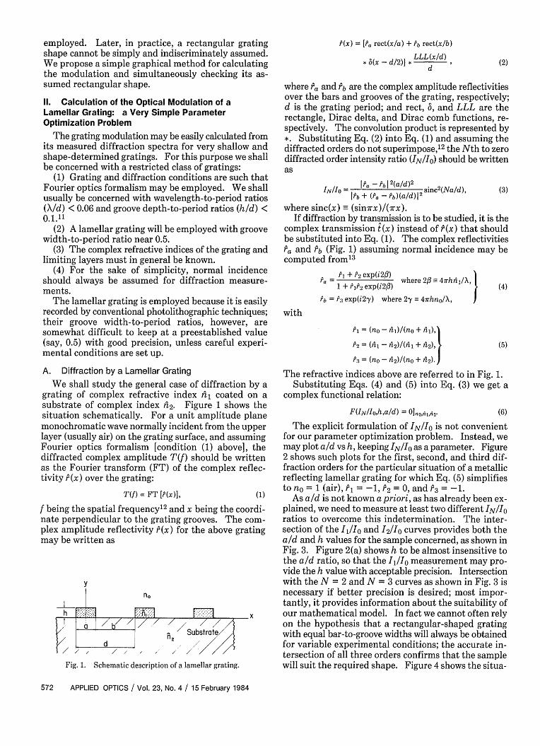
We shall study the general case of diffraction by agrating of complex refractive index fil coated on asubstrate of complex index 2. Figure 1 shows thesituation schematically. For a unit amplitude planemonochromatic wave normally incident from the upperlayer (usually air) on the grating surface, and assumingFourier optics formalism [condition (1) above], thediffracted complex amplitude T(f) should be writtenas the Fourier transform (FT) of the complex reflec-tivity P (x) over the grating:
T(f) FT [(x)], (1)
f being the spatial frequency'2 and x being the coordi-nate perpendicular to the grating grooves. The com-plex amplitude reflectivity P(x) for the above gratingmay be written as
y
n,
'771
Fig. 1. Schematic description of a lamellar grating.
(x) = [ rect(x/a) + rb rect(x/b)
* 6(x - * LLL(x/d),d
(2)
where Pa and b are the complex amplitude reflectivitiesover the bars and grooves of the grating, respectively;d is the grating period; and rect, 6, and LLL are therectangle, Dirac delta, and Dirac comb functions, re-spectively. The convolution product is represented by*. Substituting Eq. (2) into Eq. (1) and assuming thediffracted orders do not superimpose,'2 the Nth to zerodiffracted order intensity ratio (IN/I1) should be writtenas
NI I ra-b1 2 (a/d) 2
IN/IO = P - b ) 2 sinc 2(Na/d),I Pb + ra - b)(ald)
(3)
where sinc(x) (sin7rx)/(7rx).If diffraction by transmission is to be studied, it is the
complex transmission (x) instead of P(x) that shouldbe substituted into Eq. (1). The complex reflectivitiesPa and b (Fig. 1) assuming normal incidence may becomputed from'3
PI + 2 exp(i2f3)r,= w I2epif)'here 2fl3= 4irhrii/X,
1 + 9r exp(i2-y )Pb= r 3 exp(i2^y) where 2^y i- hno/X,I
(4)
with
Pi = (no - l)/(no + hi),
P2 = (n1 - 2)/(l + 2),
6 = (no - 42)/(no + 2).)
(5)
The refractive indices above are referred to in Fig. 1.Substituting Eqs. (4) and (5) into Eq. (3) we get a
complex functional relation:
F(IN/Io,h,a/d) = 0Ino,41,42 (6)
The explicit formulation of INi1e is not convenientfor our parameter optimization problem. Instead, wemay plot aId vs h, keeping IN/i1 as a parameter. Figure2 shows such plots for the first, second, and third dif-fraction orders for the particular situation of a metallicreflecting lamellar grating for which Eq. (5) simplifiesto n = 1 (air), P = -1, 2 = 0, and 3 = -1.
As aId is not known a priori, as has already been ex-plained, we need to measure at least two different IN/iratios to overcome this indetermination. The inter-section of the I1o and 12/i10 curves provides both theaid and h values for the sample concerned, as shown inFig. 3. Figure 2(a) shows h to be almost insensitive tothe aid ratio, so that the I/Io measurement may pro-vide the h value with acceptable precision. Intersectionwith the N = 2 and N = 3 curves as shown in Fig. 3 isnecessary if better precision is desired; most impor-tantly, it provides information about the suitability ofour mathematical model. In fact we cannot often relyon the hypothesis that a rectangular-shaped gratingwith equal bar-to-groove widths will always be obtainedfor variable experimental conditions; the accurate in-tersection of all three orders confirms that the samplewill suit the required shape. Figure 4 shows the situa-
Fig. 3. Compound nomogram for a metallic lamellar reflectinggrating. Superposition of figures 2(a), (b), and (c), are shown. Themeasured diffracted intensity ratios (l/Jo = 0.0651, 2/IO = 0.0007,and I3/1IO = 0.0066) for the sample shown in the top picture are plottedin bold lines. The accuracy of their intersection confirms the assumedrectangular grating shape (as in the picture). From the nomogramwe obtain h = 380 A (an independent elipsometric method gives h =
400 A) and a/d = 0.535. The period of the grating is 20 pm.
0.70-
065-
0.60-
055-
050
0.00010.001 0003 0.01 002
0.04- :~~ 0.I
0.2
0.82.0
. I~~~500 h(A) 1000 1500
Fig. 2. Nomograms for a metallic lameilar reflecting grating calcu-lated for the first [I,/Io in (a)], second [2/1IO in (b)], and third [I3/Io
in (c)] diffracted orders using Eqs. (3)-(6) with no = 1, P1 = -1, 2 =0, P = -1, and X = 6328 A. The bar width-to-period (aid) and thegeometrical modulation (h) of the grating are plotted as ordinates andabscissas, respectively. The IN/IO ratios are shown as parameters.
tion for a sample where failure of all three orders to in-tersect points out the existence of a distortion in thegrating shape as actually seen in the top pictue.
B. Indetermination of the Measured Modulation
All three graphics in Fig. 2 show an unambiguousrelationship between IN and h but for a restricted hrange. The latter range depends on the nature of thegrating and boundary layers. For the particular sit-uation shown in Figs. 2-4 (metallized reflecting lamellar
h(A 1000
Fig. 4. Nomogram for a metallic lamellar reflecting grating is thesame as Fig. 3 but for another sample as shown in the top picture.The measured diffracted orders (I/Io = 0.0592, I2/o = 0.0021, I3/10
= 0.0036) (bold lines) do not simultaneously intersect indicating thatthe sample does not fit the assumed rectangular shape (see the pic-ture). From the first-order ratio we read h = 375 A on the nomogrambut this result must be considered with less confidence than for the
same in Fig. 3.
grating limited by air), h may be uniquely determinedfrom 0 to X/4 (X being the wavelength of light employedfor diffraction measurements), because the nomogramis symmetric through h = X/4 and periodic in X/2. Fora different sample (i.e., SiO2 grating on a Si substrate)this indetermination may disappear.
Fig. 5. On ordinates is plotted the percent precision of the calculatedIt grating geometrical modulation, assuming 1% in both I, and Io as
the only error sources [see Eq. (8)].
C. Precision of the Method
The precision of the calculated h is related both tofitting the sample to the rectangular-shaped gratingmodel and to the precision of the INHio measurements.The first-order ratio (Il/o) is the most reliable variablefor the h calculation, because of its weak dependenceboth on the aid ratio [see Fig. 2(a)] and on grating shape(see the Appendix). The precision of the I1I 0 ratiomeasurement is then most relevant for determining thefinal uncertainty in h. Writing explicitly,
Ah Oh 18/0
h |(Ia/Io (if 1/JIl + IAIo/Iol) * (7)
Assuming that I, and Io are to be measured with stan-dard 1% precision, Eq. (7) turns into
Ah| - 0.021 ah I(I/I)I. (8)1h O(18I) h
The results are plotted in Fig. 5.
Ill. Calculation of the Bar-to-Period Ratio (aid)
As illustrated in the examples above, the intersectionof all INIO (N = 1, 2, and 3) ratios simultaneouslyprovides h and aid. We chose aid - 0.5 for the reasonsabove, but any value can be calculated if the propernomogram is available. If the intersection of two dif-fraction orders is to be used for calculating aid as inKleinknecht,4 attention must be paid to the fact thatprecision of the intersection (and consequently theprecision of the aid ratio) depends both on the partic-ular aid and h values, as seen in Figs. 3 and 4. Thismeans that it would be better to intersect orders 1 andI2 , I, and I3 or I2 and b3 depending on the particularsituation, so that the intersection should be as orthog-onal as possible.
The gratings chosen for illustrating this paper havelarge periods (20 gim), as we were not interested in anylinewidth measurement for resolution purposes, but themethod should be suitable for smaller periods if theFraunhofer conditions are still respected.
IV. Conclusions
We show that the modulation of a lamellar grating(and its groove-to-period ratio) may be easily calculatedfrom previously constructed nomograms which may alsobe employed for checking the suitability of their as-sumed rectangular shape. We show some illustrativeexamples for the limiting case of a metallic grating. Apriori approximate knowledge of the grating modula-tion may sometimes be necessary because of a periodicindetermination in its calculated value. For a lamellarmetallic grating its value is indetermined in X/2 multi-ples. For other samples this indetermination may al-most disappear.
The Appendix analyzes the effect of some normallyoccurring noise and shape distortions in recordedgratings and shows that low-level uniform noise shouldnot interfere with the results. On the other handasymmetric noise and shape distortion do interfere al-though the I1Io ratio is less affected, as expected, thanhigher orders.
This work aims to provide the theoretical tools forfacilitating applications of gratings for thin film thick-ness measurements and some process control. A laterpaper (Part 2) will develop the applications of thismethod to thin film thickness measurement for somerelevant situations including reflecting and transmittingsamples and its correlation with other availablemethods.
This work was supported by Conselho Nacional deDesenvolvimento Cientifico e Technol6gico (CNPq),Financiadora de Estu dos e Projetos, TelecomunicaqbesBrasileiras S/A, and Fundaqao de Amparo a Pesquisado Estado de Sdo Paulo. The authors would like tothank C. I. Z. Mammana, A. P. Mammana, F. Damiani,and E. Braga for their support and encouragement andM. Barnett and M. A. Mazotini for their technical as-sistance, all from Laborat6rio de Eletrbnica e Disposi-tivos.
Most of the experimental work was developed at theLaboratorio de Eletronica e Dispositivos (Faculdade deEngenharia) Universidade Estadual de Campinas.
Jaime Frejlich is also a fellow researcher of CNPq.
Appendix: Noise and Shape Distortion in LamellarGrating Spectra
Noise appearing during lamellar grating recordingmay produce severe distortion in its diffraction spectra.It can easily be shown that as far as homogeneous noiseis concerned, no relevant perturbation of the measuredINIIo ratios is expected. Odd distributed noise is moredifficult to handle and in general it does disturb thespectra. Shape distortion of the lamellar grating maybe treated as odd distributed noise.
The presence of homogeneous phase noise may beaccounted for by introducing a 0(x) noise term into Eq.(2), so that
P9(x) = P(x) exp[iP(x)], (Al)
with P, (x) representing the noise-perturbed P(x). Forlow level noise exp[i0(x)] 1 + i0(x)1 and substituting
+ b +(a - b ) a S (e)(I2df, (A(where 'ml represents the imaginary term.
Assuming that (x) is a large spectral bandwidth(white) noise and that the diffracted orders are mea-sured with a comparatively small active area detector,Eqs. (A5) and (A6) simplify to
(IN)n (a - b) d sinc I-N)l [1 - 2 ImIP(0)}],d \dJ
(Io)n Pb + (a - Pb) - [1 - 2 ImlJ(O))],di
( 2 (a') sinc2(aN) .(A7)
Pb + (a - b) d
Equation (A7) is the same as the noiseless relation in Eq.(3), thus showing that no perturbation arises from ho-mogeneous noise if adequately measured.
Odd distributed noise cannot be accounted for in sucha simple way. If we introduce the same O4x) noisefunction and assume it to occur on the bars of thegrating (instead of throughout its whole surface), Eq.(2) becomes
P9d(X) = Pb + (a - b) exp[iodx)] rect (- * L
Developing as above we get the diffracted amplitude
Tod(f) = Pb6(f) + a - b)[5(f)
+ i4(f)] * a sinc(af)}LLL(df). (A8)
Defining the function C(f) (f) * sinc(af) and as-
suming P(f) to be symmetric, we deduce that it and C(f)are real functions. Substituting Eq. (A8) into Eqs. (A3)and (A4) and rearranging terms we get the noise-af-fected intensity-ratio expression
( d = ( )RN,
RN
1 + [C (-3/sinc ( N)]2
a+ 2 (9 (-b) 2 2C(0) (d-) ImIPrA9b
1 b + a -Pb) Pb + P -PW)-|d I d
(A9)
where RN is the distortion factor, and Pb is conjugate torb. For low-level large spectral bandwidth noise, wemay assume that C(N/d) C(o) << 1 so that the de-nominator in Eq. (A9) may approach unity. The sincfunction is higher for N = 1 than for the subsequentorders, thus showing that RN approaches unity for N= 1 better than for higher orders in general. Thismeans that the first-order ratio (IlIo) is less affectedby such low-level large bandwidth odd distributed noise.In a similar way, or by Fourier analysis, it can be seenthat the first-order ratio is also less affected by a weak
6) shape distortion.
References1. H. P. Kleinknecht and H. Meier, J. Electrochem. Soc. 125,
798(1978).2. E. S. Braga, G. F. Mendes, J. Frejlich, and A. P. Mammana, Thin
Solid Films 109, 4, 363 (1983).3. J. Frejlich and J. J. Clair, J. Opt. Soc. Am. 67, 1644 (1977), Ap-
pendix A.4. H. P. Kleinknecht and H. Meier, Appl. Opt. 19, 525 (1980).5. H. P. Baltes, Ed. Inverse Source Problems in Optics (Springer,
Berlin, 1978), p. 42.6. R. Petit, Nouv. Rev. Opt. 6,129 (1975).7. M. G. Moharam and T. K. Gaylord, J. Opt. Soc. Am. 72, 1385
(1982).8. A. Roger and D. Maystre, J. Opt. Soc. Am. 70, 1483 (1980).9. A. M. J. Huiser, A. Quattropani, and H. P. Baltes, Opt. Commun.
41, 149 (1982).10. E. G. Loewen, M. Neviere, and D. Maystre, Appl. Opt. 15, 2937
(1976).11. Reference 8 claims from experience that scalar theory may be
accurately considered for X/d ratios < 0.2.12. J. W. Goodman, Introduction to Fourier Optics (McGraw-Hill,
New York, 1968).13. M. Born and E. Wolf, Principles of Optics (Pergamon, New York,