Gravure Stamp Cylinders Glenn H Morgan FRPSL In this three-part article, the history of the photogravure process is told, along with a step-by-step explanation of the complex procedures involved in creating a modern gravure postage stamp printing cylinder. Published in Gibbons Stamp Monthly in its February, March and April 2016 issues
Transcript
Gravure Stamp Cylinders
Glenn H Morgan FRPSL
In this three-part article, the history of the photogravure process is told,
along with a step-by-step explanation of the complex procedures involved in creating a modern gravure postage stamp printing cylinder.
Published in Gibbons Stamp Monthly in its February, March and April 2016 issues
GLENN
Text Box
Gravure Stamp Cylinders: Part 1
66 G.S.M. February 2016
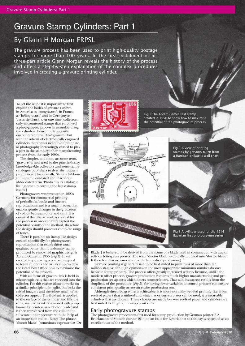
The gravure process has been used to print high-quality postage stamps for more than 100 years. In the first instalment of his three-part article Glenn Morgan reveals the history of the process and offers a step-by-step explanation of the complex procedures involved in creating a gravure printing cylinder.
To set the scene it is important to first explain the basics of gravure (known in America as ‘rotogravure’, in France as ‘héliogravure’ and in Germany as ‘rastertiefdruck’). At one time, collectors only encountered stamps that employed a photographic process in manufacturing the cylinders, hence the frequently encountered term ‘photogravure’, but with the advent of electronically engraved cylinders there was a need to differentiate, as photography increasingly ceased to play a part in the stamp cylinder manufacturing process from the early 1990s.
The simpler, and more accurate term, ‘gravure’ is now used by the print industry, knowledgeable collectors and some stamp catalogue publishers to describe modern production. [Incidentally, Stanley Gibbons still uses the outdated and inaccurate abbreviated term ‘Photo.’ in its catalogue listings when recording the latest stamp issues.]
Photogravure was invented in 1890s Germany for commercial printing of periodicals, books and fine art reproductions and is a tonal process that enables gentle changes in the gradation of colour between solids and tints. It is essential that the artwork is created for the process in order to fully exploit the potential beauty of the method, therefore the design should possess a complete range of tones.
There is possibly no stamp-like design created specifically for photogravure reproduction that extols those tonal qualities better than the dummy stamp produced by renowned graphic designer Abram Games in 1956 (Fig 1). It was created in preparing a course designed to teach students and artists employed by the Israel Post Office how to maximise the potential of the process.
With all forms of gravure, ink is held in microscopic cells that are recessed into the cylinder. For this reason alone it works on a similar principle to intaglio, but lacks the raised imagery and therefore much of its collector appeal. The fluid ink is applied to the surface of the cylinder and fills the cells, any excess ink is removed with a wiper known by printers as a ‘doctor blade’ and is then transferred from the cells to the substrate under pressure with the help of an impression roller. (Note: The phrase ‘doctor blade’ [sometimes expressed as ‘Dr
Blade’] is believed to be derived from the name of a blade used in conjunction with ductor rolls on letterpress presses. The term ‘ductor blade’ eventually mutated into ‘doctor blade’. It therefore has no association with the medical profession.)
Gravure printing is generally said to be best suited to print runs of more than ten million stamps, although opinions on the most appropriate minimum number do vary between stamp printers. The process offers greatly increased security because, unlike the modern offset process, gravure production requires much higher manufacturing and pre-production set-up costs which deters counterfeiters. That said, its success results from the simplicity of the procedure (Fig 2), for having fewer variables to control printers can ensure consistent print quality across an entire production run.
Although sheet-fed gravure is achievable, it is more normally web-fed printing (i.e. from reels of paper) that is utilised and while flat or curved plates can be used, it is invariably cylinders that are chosen. These choices are made because reels of paper and cylinders are best suited to lengthy, non-stop print runs.
Early photogravure stampsThe photogravure process was first used for stamp production by German printer F A Bruckmann of Munich during 1914 on an issue for Bavaria that to this day is regarded as an excellent use of the method.
Fig 1 The Abram Games test stamp created in 1956 to show how to maximise the potential of the photogravure process
Gravure Stamp Cylinders: Part 1
By Glenn H Morgan FRPSL
Fig 2 A view of printing stamps by gravure, taken from a Harrison philatelic wall chart
Fig 3 A cylinder used for the 1914 Bavarian first photogravure series
G.S.M. February 2016
Gravure Stamp Cylinders: Part 1
67
Cylinders had been used for that initial production run and an example (Fig 3) is held in the Museum of Communication (www.mfk-nuernberg.de) in Nuremberg, Germany.
The Bavarian stamps (Fig 4) were clearly seen as an important development and it was not long before Mexico (1917), Britain (Waterlow 1918 War Tax stamps, Harrison 1921 6d. National Savings stamps), Czechoslovakia (1919), Bulgaria and Württemberg (1920) had each followed Germany’s lead, with many more countries later taking the photogravure route.
The first photogravure postage stamps printed in Britain were by Harrison and depicted King Fuad’s portrait on a 1923 Egyptian issue (Fig 5). Use of this process is said to have come about by accident; when intaglio proofs were not ready in time and photogravure versions were substituted for speed and were favoured in Cairo. This is an oft-repeated explanation, but whether it is grounded in truth is uncertain.
Assistance with the printing of the Egyptian stamps was sought by Harrison from the experienced Dutch company, Nederlandse Rotogravure Maatschappij (NRM), in Leiden, who also helped train Harrison staff in the skills required for mass production and, more importantly in relation to this article, the creation of photogravure stamp cylinders. A range of around a dozen dummy stamp designs were printed as a part of this training exercise, of which an example is shown here (Fig 6).
The Egyptian and subsequent orders from other countries paved the way for Harrison to win major contracts to print British stamps by both photogravure and gravure between 1934 and 1997.
Cylinder creation With its major influence on all aspects of British stamp production for so many decades, the story of how Harrison created its cylinders is described here. The black and white photography in this section was taken by Harrison, circa 1967, when working on the Machin definitive series and first appeared in its brochure Harrison & Sons Limited, postage stamps / photogravure.
The reproduction and repetition of the chosen stamp design in the form of a printing cylinder was, in theory, a matter of routine photography and etching, though in practice a great deal of highly-skilled control was necessary during the various stages. The description of the process has, in large part, been explained here using an internal document created by Harrison in 1945 for the New Zealand postal authorities. The process continued to be applied virtually unchanged until the eventual demise of the photographic method.
The master negative The approved designs would have been created by the stamp designer at four times intended stamp size (‘four-up’) and would be improved for printing purposes by the team of process artists at Harrison, if needed. The artwork was then photographed (Fig 7) at twice the intended stamp size through coloured filters that
would separate each colour required. Ten timed exposures of each ‘two-up’ negative would then be printed and the best result noted for each colour. From this, a master glass (or subsequently film) negative (Fig 8) for each intended stamp colour was produced.
Colours and gear designationsNote that at this time in stamp production history, the ‘four colour process’ (or CMYK, standing for Cyan, Magenta, Yellow and Key [printing terminology for black]) was not in use on stamps from Harrison. Instead, inks were individually mixed, with more than four colours, and therefore more than four cylinders, frequently being required.
Incidentally, it was as early as 1906 that the four-colour wet process inks were used for the first time by the print industry after it was discovered that these CMYK colours could be combined to produce an almost unlimited number of richer, darker tones. Stamp printers generally lagged behind in adopting this important cost and speed saving development.
Fig 4 An imperforate stamp for Bavaria from the 1914 series
Fig 5 A proof of the Egyptian stamp by Harrison in 1923 Fig 6 A Harrison dummy
stamp from the NRM cylinder production trials
Fig 7 Photographing the original artwork
Fig 8 Checking the master negative against the original artwork
Gravure Stamp Cylinders: Part 1
G.S.M. February 201668
‘Gear designations’ (Fig 9) can be found on reel-fed printings (in many instances they were either partially or completely trimmed off the counter sheets). They acted as guides for the mounting of a cylinder onto a print unit and had two functions:
1. Orientation: how the cylinder was to be mounted—the ‘G’ refers to the ‘Gear Side’ of the print unit. (Spindles to this day are the same on both sides, so a cylinder could inadvertently be inserted the wrong way round in relation to other cylinders, causing an inverted print of that colour.)
2. The print unit sequence—‘G1’ the � rst print unit, ‘G2’ the second unit and so on indicating the sequence by which each colour was to be printed.
Named colours do not always correspond to the actual colour printed; gear sequence numbers are not always present, just the letter ‘G’ for each colour used.
Essaying During the development phase, essays would be produced on plates and printed on a proo� ng press. These may have been just a single image output or a number of images. Any number of these may have been produced as this would have largely depended on the subject and development effort involved.
Multi-positives Each master negative was placed into one of three Harrison ‘step and repeat’ cameras (Fig 10) and the image projected onto a large glass sensitised photographic plate.
After suitable exposure of the � rst stamp at its intended size, an elaborate piece of machinery, precisely linked to the timing of the camera shutter, moved the glass plate by gearing of extreme accuracy into position for the next exposure (Fig 11).
Prior to 1973, the gears and cogs meant that it was slightly erratic and was the source of Machin ‘� oating values’. From 1973, the step and repeat cameras were computer-assisted and this brought about signi� cant improvements in precision and virtually, if not altogether, eliminated the inaccuracies.
Eventually, suf� cient exposures onto the multi-positive had been captured. Records held at The Postal Museum (formerly the BPMA) show, in the case of de� nitives, that the norm was for the size of the multi-positive to contain many more images than that required for the standard primary sheet laydown, as seen in Fig 12. Therefore the expected multi-positive image sheet sizes of 480/240 (pre-decimal Machin) or 400/200 (decimal Machin) would have been
Fig 9 Harrison 3d. 1965 Salvation Army � ve-colour commemorative with marginal markings de� ning what colour ink each cylinder should be printed from, together with its gear designations
Fig 10 A ‘step and repeat’ camera showing a paper tape system for positioning each image correctly. Harrison, c1973
Fig 11 The principles of a ‘step and repeat’ camera system. Harrison, c1973
Fig 12 Inspecting the multi-positive. Note the ‘spare’ Machin stamps beyond the sheet margins, indicating that far more exposures than required had been made
February Gravure Stamp Cylinders Part 1.indd 68 06/01/2016 12:44:47
G.S.M. February 2016
Gravure Stamp Cylinders: Part 1
69
the exception rather than the rule, with a staggering 1073 images recorded on one multi-positive.
With the move into the decimal period, the multi-positive creation/usage technique changed. Wilding and pre-decimal Machin de� nitives had the head and value tablet combined for the master negative to create a single multi-positive. However, for the decimal period, a head multi-positive was created and then value tablet multi-negatives. Thus, any given value tablet multi-negatives would be over-laid onto a common head multi-positive. The records seem to suggest these value tablet multi-negatives were more likely to be primary sheet sized (400/200 images). [A primary sheet was created by selecting a portion of the multi-positive and masking out unwanted images—this methodology meant that ‘no dot’ and ‘dot’ panes were perfectly synchronised across the extent of the imaged area. These two adjacent panes with central gutter are clearly seen in Fig 12.]
The multi-positive, when developed, � xed and checked was next taken to the planning room where certain other details were added, such as a cylinder number, imprint and registration markings (Fig 13).
The base cylinder Harrison engineers created the base cylinders on-site at High Wycombe. Made of steel, they were coated with copper by a chemical electrolyte process in a bath of copper sulphate and after � nishing had a perfectly true and polished surface. Collectors over the years have recorded that the cylinders were made of solid copper; they were not.
When printing long runs of, say, � rst and second class values, Harrison would sometimes prepare a back-up set of cylinders so that if an unexpected replacement of a cylinder was required it did not mean that the press ground to a halt while a new image carrier was prepared.
An expensive resource, cylinders would be recycled at the end of a print-run (unless a reprint was likely in which case it would be stored). When not required again, the old images would be ground off and a fresh layer of copper would be deposited, ready for the next stamp issue.
Carbon tissue Carbon tissue was a temporary support sheet comprising a water-sensitive � brous paper coated with a perfectly true and smooth gelatine resist surface. It was sensitised by immersion in a solution of bichromate of potash and contained an orange dye to assist when viewing the screening and multi-positive imagery.
Screening Before the stamp images were transferred to the cylinder, a glass plate with a surface of opaque squares enclosed by transparent lines was printed onto the tissue. The point of the screen was to break-up the overall design on the printing surface (for our purposes the press-sheet of stamps), into small cells that would hold ink between walls corresponding to the transparent lines on the screen.
At some point, and without warning, carbon tissue was no longer able to be purchased and cylinder production was therefore put at risk. Fortunately, a
replacement product from Autotype, known by the brand name of ‘Auto� lm’, was sourced. Despite some collector assertions that this was supplied pre-screened at, say, 250 screen lines to the inch, this has recently been refuted by two ex-Process Managers from Harrison.
Exposing the carbon tissue Exposure of the carbon tissue was a two-stage operation. Firstly, the tissue for one of the colours was placed behind the screen in a special frame in which close contact was obtained by suction, and the frame was exposed to strong arc lamps for a given time. Where light penetrated the transparent screen lines, the gelatine was rendered hard and insoluble (this property of the sensitised gelatine was key to the whole process).
The same piece of tissue (with its newly applied screening) was then exposed again, this time behind, say, the ‘480-set positive’ (i.e. the press-sheet of stamp designs, or multi-positive). This hardened the gelatine in the parts corresponding to the lightest portions of the stamps and the gutters between the stamps, which were transparent in the positive. In the dark portions of the stamps the light did not reach the gelatine,
Fig 13 Adding register marks to the multi-positive
Fig 14 Laying the carbon tissue onto a polished copper cylinder
which was therefore unaffected. In the mid-tones, the gelatine was only partially hardened.
This piece of carbon tissue now had both a screening and the multiple stamp design on it and so was therefore ready to be transferred to the printing cylinder. The process was repeated for each additional colour to be used on the stamp.
Carbon tissue to printing cylinder The next stage was to use the gelatine as a ‘resist’ to control the etching of the printing surface.
The carbon tissue ‘skin’ was pressed into close contact with the copper-covered cylinder, a spray of water being directed to the point of contact, as seen at far left of Fig 14. After the tissue had been correctly mounted, it was ready for development.
The tissue backing was soaked off from the revolving cylinder with hot water, along with any unhardened gelatine, which got washed away. This left a raised pattern in gelatine on the copper corresponding to:
(a) the whole of the transparent lines in the screen pattern, and also the gutters between the stamps, plus:
February Gravure Stamp Cylinders Part 1.indd 69 06/01/2016 12:46:47
G.S.M. February 2016
Gravure Stamp Cylinders: Part 1
70
(b) the light portions of the design, the thickness of the gelatine being proportionate to the lightness of the tone.
The process would take around 15 to 20 minutes and when completed the cylinder was sprayed with very cold water and dried by an electric fan.
Margins and other areas of the cylinder not required to be etched would then be carefully painted over (Fig 15) with an acid-resisting varnish prior to etching.
Etching The cylinder was revolved in a trough containing ferric chloride (FeCl3), also called iron perchloride and iron trichloride, which bit into the copper where it was not protected by the gelatine ‘resist’.
The control of this operation called for much skill and experience, and as many as seven different strengths of solution, seen in Fig 16, might be used for bringing out tones of different depths enabling the gradual transition from one colour hue to another, from one shade to another, or one texture to another. There was no suitable ready-made solution available and the skilled craftsmen used their judgement based on years of experience as to what strengths to use.
When etching was deemed complete, the acid-resisting varnish and the gelatine ‘resist’ was washed off in warm water, which dissolved the unhardened (non-image) areas and left the required images to print from. The cylinder was then given a final polish.
There is an interesting eccentricity with carbon tissue and the use of acids that flies in the face of expected results, as explained by stamp and banknote engraver Chris Matthews:
‘The more aqueous solution [i.e. the water used in the dilution of the acid] that is applied to the carbon tissue, the more the carbon tissue would “open up”, causing the acid to etch the image to a far greater extent. So, somewhat counter intuitively, the weaker the acid solution, the greater it would etch, while the stronger the acid, the less it would etch the cylinder.’
Proofing The next procedure was to print proofs to check for defects, which would be circled in ink or pencil on the sheets. It was then possible for experts to manually amend the cell structure to correct these odd imperfections (what collectors call flaws or varieties) that may have been present, a process seen underway on the dummy stamp depicted in (Fig 17).
After correcting, further proofs were pulled from the cylinders until they were deemed accurate. It is interesting to note that the proofs were all printed using the unchromed copper cylinders, much like an intaglio engraver pulls proofs of his unhardened die—fine for a few impressions, but not suitable for a production run, due to likely wear and tear and risk of damage.
Chroming Before the cylinder could be used for a print run, 6 to 8 microns of chromium would have been deposited via an electro-plating method. It would not have affected the etched cells (Fig 18) to any significant degree, although the shallower the depth of a cell, the greater percentage the chromium represented.
Hard chromium plating baths were first
introduced commercially in 1930 to provide a tougher surface for printing cylinders by avoiding tarnishing and wear by friction between the paper and the cylinder, thus prolonging their life and saving costs.
Thanks to its tough metal qualities and fine grain structure, the introduction of chromium, which has not been bettered to this day and is still used to protect electronically engraved cylinders, enabled clearer, sharper detail across the entire print run. From the first through to the last stamp sheet printed, impressions were not subjected to a slow deterioration the further you got into the production run.
Re-chroming At set intervals, the cylinders would be
Fig 15 Painting over areas not to be etched at Harrison, early 1960s
Fig 16 Preparing a gravure cylinder by hand-etching with varying strengths of acid
Fig 17 Manual amendment of a photogravure cylinder. Harrison, early 1960s
Fig 18 Macro image of cells before the era of electronic engraving. This example is for one of Royal Mail’s 1987 Studio Pottery stamps. Cells have always been deemed to be the most important part of the gravure process. The quality of the printed image depends to a great extent on the cell structure
G.S.M. February 2016
Gravure Stamp Cylinders: Part 1
71
What might have been A method that could have been very influential in the creation of stamp cylinders never came about following initial trials in 1980 at Harrison. This was known as the ‘Lasergravure System 700’ and was developed by Crosfield Electronics Ltd.
Unusually, the screen comprised horizontal lines rather than dots and the printing cylinders, which were plastic coated, could be engraved by laser. This was seen as a means of providing gravure printers with a less labour intensive process for creating cylinders and one which would no longer require the use of acids in use at that time for the production process.
A letter from Aubrey Walker of the Post Office Procurement Executive to K Scrimgeour of Harrison dated 30 October 1980 comments on the ‘Giant Machin Heads’ (Figs 19 and 20) produced during the trials. Walker said:
‘I can see how the definition could be improved to meet required standards’ and proposed that stamp-sized examples should be produced and that ‘if this is successful, PHQ (postal headquarters) will select the original artwork of two Special Issue stamps previously printed by
Harrison and these can be Lasergravure printed for direct comparison with the photogravure versions.’
It appears that the stamp-sized Machin head stamps mentioned were never produced and the project eventually died without further proofing exercises, in part due to the plastic cylinders easily scratching and therefore regularly printing defective trial stamps.
checked and, where required, some ‘stripping and refacing’ would be undertaken, i.e. the surface would be removed by de-chroming and then would be re-chromed. Rarely on stamp products would the cylinder be left on press until wear was detected. It should be borne in mind that the act of re-chroming to this day carries a penalty in that some degradation to the print quality can occur by the use of this procedure.
Once all of the complex preparation work had been completed, the cylinder would be mounted on the press and the printing stage would commence, but this is beyond the scope of this article.
My next instalment will describe modern electronic engraving methods along and will include a report on my visit to Saueressig, where gravure cylinders are made for the British stamp printing operations of De La Rue plc and International Security Printers Ltd.
Fig 19 The A4 Machin Head trial from Crosfield and Harrison, 1980. 13 sheets survive, of which only eight are undamaged
Fig 20 A close-up of part of the large Machin head design
Enjoy the prospect of seeing some of the 1 million stamps that we stock. Unlike eBay, you have 15 days to dwell on your stamps with no immediacy to purchase. You can inspect both sides of the stamp. Many
of our customers tell us that the quality of stamps on eBay does not meet expectation.We attend Stamp Auctions every week of the year and so are able to select the fi nest quality, unlike
Stamp fair dealers who are often not able to attend weekend auctions.Over 40 years of dealing in approvals, we have become the premier dealership in Worldwide countries. We have a team of fi ve experts, all of whom have 30 or more years experience of philately. We pride ourselves on excellent customer service and routinely receive praise from our hundreds of customers,
many of whom have been with us for over 20 years.Call us on 01923 269775 to speak to my son or myself to support your hobby. Alternatively, email or complete the coupon stating your countries of interest. View in the comfort of your home for up to 14 days.
With traditional cylinder production techniques covered in Part One of this article, published in the February issue of GSM, Glenn now integrates the story of modern production methods with his visit to stamp cylinder manufacturer, Saueressig.
It was inevitable that newer technologies would one day take-over from many of the old-fashioned procedures described in Part One of this article as a means of getting stamp imagery onto a cylinder. However, unlike the video recorder wars (Betamax versus VHS), where the latter was to reign supreme, the two main engraving systems co-exist, with each having their devotees.
These systems are now the most commonly used means of cylinder imaging for postage stamps and commercial printing worldwide, coming about as a direct result of advances in electronic technology. They have their origins back in 1959 when the first gravure reproduction based on electronic engraving techniques occurred at what is now Hell Gravure Systems, but around three more decades were to pass before these advances were utilised for British stamp production.
Engraver brands and systems The ‘wars’ relevant to electronic engraving are DLE (Direct Laser Engraving) versus EME (Electro Mechanical Engraving), with the short form EME wrongly being applied by most collectors to both types of engraving method. Perhaps ‘electronic engraving’ is a better generic expression, as used here, because it can apply equally to DLE and EME.
DLE: These electronic engravers are mainly supplied today by Hell Gravure Systems GmbH [Germany] which uses lasers to create the cells. Hell (who also offer EME equipment) are the market leader in DLE with its roots being in the invention of EME by Dr Rudolf Hell. Core areas today are ‘packaging and publication gravure and flexographic printing’. Daetwyler, from Graphics AG [Switzerland], is a brand once utilised by Walsall in the 1990s.
EME: The current leading brand name for EME engravers is Ohio from Ohio Gravure Technologies Inc [USA], which employs a diamond stylus tool to create cells. Ohio describes itself as ‘an engineering research and development, manufacturing and software development company’. Founded in 1978, it has ‘a broad and deep expertise in gravure printing’ with its customer and equipment base extending to 50 countries.
Incidentally, whether acquiring Ohio, Hell or Daetwyler engravers, the purchaser is buying from the same group, as all three companies are partners of Heliograph Holding GmbH of Germany.
Gravure Stamp Cylinders: Part 2
By Glenn H Morgan FRPSL
Usage of electronic engraving on GB stamps Royal Mail standardised on gravure as its preferred method for printing definitive stamps, since it is considered to be a more secure process. Gravure is expensive, hence its limited use on special stamps, although it is still used for Pressure Sensitive Adhesive (PSA) specials because printing on the web is a necessity for these stamps as there is the need to die-cut and, invariably, matrix strip the stamps. These procedures are not feasible if printing on pre-cut sheets, which is often the method used for litho-printed stamps.
Electronic engraving offers far better detailing, with the differences being quite noticeable when comparing actual stamps side-by-side with traditionally etched examples.
All printers of British stamps eventually utilised electronic engraving and details of when they adopted a system along with initial output for Royal Mail follows.
Enschedé (1990): This Dutch printer produced the 18p definitive in late 1990 using cylinders that had been electronically engraved in-house using its Hell EME Klischograph system, virtually eliminating constant flaws and sharpening stamp images at a stroke. 1994 saw the release of the ‘Europa: Medical Discoveries’ set, the company’s first British commemoratives by this method. Enschedé had set a benchmark that other printers of stamps had to follow.
Harrison (1996): This printer continued with acid-etching until 1996, first using the Hell DLE system for the ‘Centenary of Cinema’ commemorative issue. Its initial use of electronic engraving for definitive stamps was probably in late 1996 for 2nd class NVI coils.
Walsall and House of Questa (1997/8): Having to purchase gravure production equipment if they wished to continue printing definitive stamps for Royal Mail meant that Walsall and Questa were late-comers to that process and could go straight to electronic engraving, bypassing traditional carbon tissue methods of cylinder making. Walsall’s first gravure definitives appeared in 1997, along with the ‘Europa: Horror Stories’ commemoratives that same year. Questa followed, with definitives in 1998 and the Millennium: Patients’ Tale set in 1999.
Cylinders for the long-running Machin head design have moved from an etching method to electronic engraving...
Traditional methodAcid-etching and original multi-positive head.Basic quality
Interim EME An advance, but still using original multi- positive head.Improved quality
Modern EMEEventually, a digitally remastered Machin head was made.Finest quality
A clash of screens...Collectors had generally understood that there was no way of identifying whether a stylus or a laser had created the cylinder cells when examining an enlargement of a multi-coloured postage stamp; however this is not the case according to Saueressig.
To tell if an EME or a DLE engraver was used, check for ‘screen-clash’, as only EME can create a complete ‘rosette’ pattern - DLE rosettes will always look imperfect.
(Unsurprisingly this method cannot be used if examining a mono-coloured stamp, such as most Machin definitives, as there is only one screen used and therefore nothing to clash with.)
De La Rue (1998): The first De La Rue imprint appeared on a British gravure commemorative set in 1998 (Children’s Fantasy Novels) after having bought Harrison the year before and continuing to use its High Wycombe facility and equipment, thereby re-entering the stamp production market by default. The company continued to use cylinders with a Harrison imprint in the margins of its definitive sheets for some considerable time after 1997, as they were perfectly serviceable.
A strategic decision was made by De La Rue that it would outsource cylinder making, possibly as a result of its 2002 purchase of Questa, for they were primarily using Apex Cylinders by this time.
G.S.M. March 2016
Gravure Stamp Cylinders: Part 2
73
With the background story behind competing electronic engraver types and initial usage on British stamps now told, it’s time to go behind the scenes at stamp cylinder manufacturer Saueressig and to record the current processes used by them for Royal Mail products.
From Apex to Saueressig ‘Apex Cylinders Ltd’ was founded in Bristol during 1990, initially as specialist engineers manufacturing gravure printing cylinders, later adding graphics division ‘Studio 404’.
After five years experience in the high quality end of the gravure market (mainly tobacco), Apex first approached The House of Questa in 2000 regarding manufacturing stamp cylinders for them. The first orders were received in 2002 with the intention of Apex supplying 10 per cent of their requirements. Within 12 to 18 months, 90 per cent of Questa’s requirements were being met by Apex. This formed the basis of the current relationship with Royal Mail.
De La Rue (purchasers of Harrison in 1997 and Questa in 2002) and International Security Printers (ISP) both outsource to Apex, or rather to ‘Saueressig Ltd’, for on 20 July 2015 there was a company name change to reflect the title of its parent company, which had been founded in Germany during 1953. Saueressig has always been a part of the Apex business, having been an initial shareholder.
At the time of the change, a spokesperson for Saueressig Germany said:
‘The qualities that gave Apex Cylinders its competitive advantage—its diverse range of products and services, a strong commitment to customer service, a firm belief in core values and most importantly, a skilled and dedicated workforce—remains unchanged. Subsequently all rotogravure companies within the brand deployment division of Matthews International will be aligned within the Saueressig brand. This move will both enhance and enrich our identity, ensuring a more unified and successful future.’
Important though this name change is to the group, for the 50 staff at the Bristol site it is very much ‘business as usual’, with everyone continuing to meet the diverse requirements of its many clients and adhering to the ever-present (and ever-tighter) deadlines.
A visit to the firm afforded an opportunity to witness modern developments (Fig 1) and to see how electronics have improved the quality of modern stamps. Emphasis is on Ohio stylus engravers, but general principles apply equally to the Hell laser machines used at the Haarlem premises of Joh. Enschedé, as it is primarily cell creation methods that differ.
Saueressig provides Britain’s most comprehensive range of highly automated production facilities (Fig 2) in the tobacco, security, flexible packaging and decorative markets and is the only company in this country that engraves postage stamp cylinders. The Saueressig presence in Turkey (trading as Kroma Pre-Press Preparation Systems until last
July) produce cylinders for printers that supply Posta Telgraf Tes’kilatı (Turkey Post) with its
stamps. Being a part of the much larger Matthews International group (a global brand based in
the United States with its main interests in memorialisation services), means that Saueressig UK has access to a full range of equipment worldwide (such as Hell DLE machines) to meet the needs of its customers in rare instances when it cannot fulfil directly from Bristol.
Modern cylinder production: Artwork, ‘repro’ and colour management For 14 of its 25 years, Apex, currently via De La Rue and ISP, has worked with Royal Mail, providing it with artwork, repro, colour management and cylinder making facilities for British stamps in all formats.
Criteria: Stamp work is undertaken by Saueressig’s graphics division, Studio 404, based on the same site as the engineering division. When a new Royal Mail stamp project is presented, the studio will need to know various criteria before it can start work, such as:• type of substrate to be used (water-activated [WAG] or pressure-sensitive / self-adhesive [PSA]), • what printer will produce the job (generally De La Rue or ISP, but it could be others, such as with the Olympic Games in 2012), • what type of printing process will be used (usually gravure, but offset pre-press work is also undertaken, but not the subsequent making of offset plates), and • whether there is an agreed ink supplier (invariably Sun Chemicals or SICPA).
The answers provided to these questions will enable an appropriate workflow unique to that project to be created, as with other retail products, such as cigarette packets and crisp bags.
Visuals: These are produced by Royal Mail, the creative agency or solo designer and are sent to the chosen stamp printer to indicate how the stamps might look. Most of the time an Epson or other digital proof will be supplied to Studio 404 and while it is a good rendition of the final stamp, it is not a fully accurate version. It does not, for example, take into account that the proof may be on a slightly yellow paper, or that it is to be printed on a self-adhesive stock so may eventually have a slight grey or blue hue to it.
Artwork: The printer supplies the basic artwork � le (i.e. any material or image prepared for graphic reproduction) and once it has been booked into the production system it will be examined to see if there are any immediate questions. When all answers are to hand, the � le is manipulated and output as a solitary image � le (i.e. one copy of a single stamp design).
With artwork � les (as created by Royal Mail or its agency), every colour butts-up to each other without any white gaps or overlapping between design elements. It is not a � le that can be used to print from, that is called ‘repro’ (reprographics: the process of producing colour separations from artwork for image carrier production).
Repro: Clients may choose to let Studio 404 undertake repro from supplied artwork, or the studio uses pre-supplied repro direct from the client, in which case Postscript � les (a page description language from Adobe that describes the contents and layout of a page) are created enabling the studio to turn the � le into electronic engraving data. This is achieved by a software package called ArtPro (a full-featured pre-production editor, similar to Adobe Illustrator) that is highly accurate allowing massive enlargement on screen and colour separations.
Colour ‘traps’ (trapping: the ability to print a wet ink � lm over previously printed ink) are added, whereby certain colours are overlapped by other colours (Fig 3) to avoid white lines between design elements. Generically within security print traps are much smaller than for commercial print.
Marginal inscriptions are speci� ed by Royal Mail and, depending on the printer, Studio 404 will either incorporate the inscriptions or they will already be on the complete repro supplied. Registration markings that are unique to each press type are also added to the electronic � le at this stage to ensure accurate registration when printing is underway. Much to the disappointment of collectors, a good deal of this information gets removed when guillotining the printed press sheet down to counter sheet size (or other format, such as booklets). That said, some colour control strips frequently remain on the margins of the issued item.
The image for a stamp is invariably stretched beyond its intended size when preparing repro, as most materials are unstable and the gravure process involves solvent-based inks that have to pass through a drying unit at each colour station and this intense heat progressively removes moisture from the substrate, shrinking each stamp as it passes through the press until it eventually reaches its intended size.
Inks: It may seem odd that Saueressig is involved with inks, but the formulation chosen is a crucial element because, even for the same colour, the ink mix used with WAG papers would be different to that used with PSA papers. This is because the translucency of the ink takes on some of the colour of the substrate below it and impacts on the appearance of the � nished stamp. If this aspect was to be ignored, an identical stamp printed on both WAG and PSA paper would potentially be visually different.
With the creation of any ink mix, you start with a range of 12 colours to make all other
colours and shades required for the printing process. Inks are of different formulations, so Pantone 123 (yellow), for example, does not exist as a pure yellow ink but comprises yellow, plus some red and maybe a little orange. The ‘recipe’ will be tweaked until the correct printed result required by Royal Mail is obtained and will be saved as an ink formulation for the next time that it is required on the same substrate. This attention to detail by Studio 404 is a great help to the stamp printer, as it gets them 95 per cent of the way there, leaving the stamp printer to simply make � nal adjustments.
The smaller the engraved cell, the larger proportion the pigment represents and the greater chance of ink getting stuck in a cell, especially for metallic or white inks with their platelets (particle sizes) gradually clogging-up the cells. While normal organic inks are � ne, it is a further reason why Saueressig needs to be involved with knowing what inks will be used.
There are times when ‘electrostatic assist’ (ESA), known as Electrosist in America, is used by printers, whereby electrostatic forces help draw ink from the gravure cells, ensuring � ne reproduction and the avoidance of white unprinted cells (the ‘snowy’ effect sometimes seen on stamps without ESA). If organic inks are used at the beginning of the press and the printer wanted to use the assist that would be � ne. Similarly, if they then wanted to print metallic that would also be okay. However, if the printer needed to print metallics � rst and then follow that with organic inks they would not be able to use ESA because of the fear of arcing and other � re risks that health and safety regulations rightly control.
Substrates and cylinder circumferences also play a part in releasing ink from cells. Depending on the press, paper may run through at between 60/100 metres a minute for stamps, whereas commercial packaging is around 300/500 metres, as � nal quality is less critical. Similarly, a 350mm or a 700mm circumference cylinder reacts differently when on press owing to rotation speeds.
Mock-ups: The studio now has a full mock-up facility for packaging prototypes (‘concept proo� ng’), but this would not generally be of use to Royal Mail unless a major new packaging format for a product, such as presentation packs, was contemplated.
Colour management: Much of the work done within colour management is software based, with GMG being the favoured suite of packages used by Studio 404. Adobe describes a Colour Management System (CMS) as:
‘a collection of software tools designed to reconcile the different colour capabilities of scanners, monitors, printers, image-setters, and printing presses to ensure consistent colour throughout the print production process. Ideally, this means that the colours displayed on your monitor accurately represent the colours of the � nal output. It also means that different applications, monitors, and operating systems will display colours consistently.’
Single image proo� ngWith preparatory work completed, ‘contract proo� ng’ in the form of a paper proof (‘hard copy’) or online proof (‘digital PDF’), is undertaken. The importance of stamps to Royal Mail means that they will go back and forth via its printer, retouching and amending for up to a week, until it gets a single-image proof that has the quality of reproduction that it seeks. Incidentally, what a collector calls a proof, Royal Mail refers to as an essay, even in instances where the proof is not changed prior to sign-off.
Once the Stamp Advisory Committee has given its approval and the proofs (essays) have been provisionally approved by Royal Mail, they are submitted to HM The Queen for her approval. Only after Royal approval has been given can the printer get Saueressig to manufacture � nal cylinders with multiple images for printing.
From one stamp image to manyThe process of turning an approved single stamp into many stamps is known as the ‘step-and-repeat’ stage, and involves production of a computer � le for counter sheets, booklets, miniature sheets or other format. This replication is done at Studio 404, by the printer or at Royal Mail.
Image processing Two different methods can be used for image processing (the creation of a master computer � le of stamp repro in a press-sheet format) when using electronic engraving systems. The � rst type involves a direct positive photographic � lm image mounted on a synchronised rotating drum. The data is read by an electronic scanner, digitised and processed ready for subsequent engraving. The second method, as at Studio 404, is via direct electronic transfer, where the image information is scanned and transmitted to the engraver for outputting.
A greyscale TIFF image � le is created for each colour separation, which is passed to the engineering side of the business to create the cylinders.
EME Cylinder preparationTimescales: Two decades ago a cylinder maker might have been given � ve weeks to turn around a job, but today that timescale is down to between � ve and ten days. This is partly due
March Gravure Stamp Cylinders Part 2.indd 74 04/02/2016 16:14:29
G.S.M. March 2016
Gravure Stamp Cylinders: Part 2
75
to newer technologies, but also higher client expectations.
Physicality: Stamp cylinders are created uniquely for each printing press, so there is no standard specification, sufficient to say that they vary from roughly 500 to 1100mm in width, weigh between 40 to 150kg and have a circumference of circa 500 to 700mm.
Components: Cylinders comprise three parts: a hollow tube, or inner core, made from ex-Russian gas pipeline, end caps welded to the tube and a spindle (or shaft) fixed centrally to each cap to enable mounting and subsequent rotation on the press.
Upright and inverted: The shape of the spindles are identical at each end, so a cylinder, as seen on a De La Rue dummy stamp (Fig 4), could potentially be mounted onto the press one of two different ways, resulting in the complete sheet coming off the press either inverted or upright. This difference is not noticeable, or of concern, when single sheets or individual stamps are viewed by an average stamp collector. However, for philatelists interested in the Direction of Print (DOP), they may find that a stamp reprint has a different DOP to the original printing, meaning cylinders had all been mounted the opposite way when reprinting.
The nightmare scenario would occur when one cylinder out of, say, four is mounted the opposite way to the rest, hence Harrison at one time using ‘Gear designation’ markings (see Part One) to avoid this unthinkable prospect.
Base stock: Engraved cylinders are produced from two types of base stock. There are the old cylinders (Fig 5) that have been returned to Saueressig for re-use bearing an obsolete image and a chromed surface, and new cylinders (Fig 6) with a bare steel surface. Both types are processed in a different manner before being put into initial, or repeat, service.
Old cylinders are first chemically ‘de-chromed’, which still leaves the imagery on the cylinder at this stage. The top layer of copper with its obsolete design is then ‘skimmed off’ on specialist equipment and a new, additional, layer of copper is deposited on the surface (Fig 7), building up the circumference to the precise measurement required.
Fig 4 A De La Rue printing cylinder with its identical shafts
Fig 5 Cylinder deliveries back from the printers, covered with grease and ink and awaiting processing
Fig 7 The copper bath, which uses a similar procedure to the nickel and chrome baths
Above: Fig 6 Brand new steel base cylinders for future use
G.S.M. March 2016
Gravure Stamp Cylinders: Part 2
76
New base cylinders comprise 10 to 15mm thick mild steel tubes with a specially finished surface. These are given a layer of nickel (Fig 8), which acts as a 5 to 10 micron primer layer and gives the subsequent copper layer (Fig 9) something to grip onto, for without it there would rapidly be de-lamination and separation of the surface because steel is not a suitable face for copper to adhere to.
Metal deposition: Both the nickel and the copper deposition is applied by the electro-plating method using electrolytes and a charge. The cylinder is fully or partially immersed in a bath containing copper or nickel ingots, which are given an electrical charge and the rotating cylinder slowly becomes plated with either the nickel or the copper. In the case of the copper, it is applied just in excess of the desired circumference to allow a ‘surface profile’ to be created (see Part Three). This whole process can take up to eight hours, depending on the amount of metal to be deposited, and is a process virtually unchanged for more than a century Fig 10 shows a photograph taken in 1913 depicting a copper-faced plate about to receive a nickel deposit at printer Eyre and Spottiswoode.
Next time: Glenn concludes the story of modern electronic engraving and his visit to Saueressig.
Fig 8 A cylinder after receiving its primer layer of nickel
Fig 9 Cylinders with a copper layer grown over the nickel
Fig 10 Aside from it being a plate instead of a cylinder, little has changed in more than 100 years. The modern-day baths at Saueressig would be instantly recognisable to the young man in this 1913 photo
Enjoy the prospect of seeing some of the 1 million stamps that we stock. Unlike eBay, you have 15 days to dwell on your stamps with no immediacy to purchase. You can inspect both sides of the stamp. Many
of our customers tell us that the quality of stamps on eBay does not meet expectation.We attend Stamp Auctions every week of the year and so are able to select the fi nest quality, unlike
Stamp fair dealers who are often not able to attend weekend auctions.Over 40 years of dealing in approvals, we have become the premier dealership in Worldwide countries. We have a team of fi ve experts, all of whom have 30 or more years experience of philately. We pride ourselves on excellent customer service and routinely receive praise from our hundreds of customers,
many of whom have been with us for over 20 years.Call us on 01923 269775 to speak to my son or myself to support your hobby. Alternatively, email or complete the coupon stating your countries of interest. View in the comfort of your home for up to 14 days.
With Part 1 of this article having recorded traditional cylinder making processes and Part 2 detailing modern gravure methods up to the metal deposition stage, Glenn Morgan now completes the story of electronic engraving. In this final instalment he discusses the high tech preparation methods, intricate proofing stages and final inspections in place in order to deliver the perfect printing cylinder.
In last month’s article I began to discuss the processes involved in modern-day gravure printing, from the different electronic engraving systems available, and methods of repro and colour management, to the initial preparation of the cylinders for engraving. In this concluding part of my article we look at the remaining processes involved in the creation of a fully-engraved cylinder ready to be used by the printer.
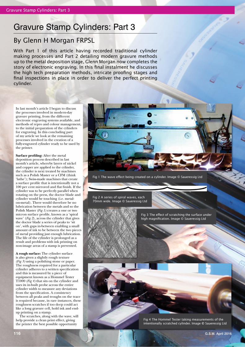
Surface profiling: After the metal deposition process described in last month’s article, whereby layers of nickel and copper are applied to the cylinder, the cylinder is next treated by machines such as a Polish Master or a CFM (think ‘lathe’); Swiss-made machines that create a surface profile that is intentionally not a 100 per cent mirrored and flat finish. If the cylinder was to be perfectly parallel when rotating on the press, the doctor blade and cylinder would be touching (i.e. metal-on-metal). There would therefore be no lubrication between the metals and so the Polish Master (Fig 1) creates a one or two micron surface profile, known as a ‘spiral wave’ (Fig 2), across the cylinder that gives the doctor blade a series of peaks to ‘sit on’, with gaps in-between enabling a small amount of ink to be between the two pieces of metal providing just enough lubrication. The life of the cylinder is prolonged as a result and problems with ink printing on non-image areas of a stamp is prevented.
A rough surface: The cylinder surface is also given a slightly rough texture (Fig 3) using a polishing stone or paper. The roughness required for a particular cylinder adheres to a written specification and this is measured by a piece of equipment known as a Hommel Tester T1000 (Fig 4) that sits on the cylinder and uses its in-built probe across the entire cylinder width to measure any deviations from the specification. A consistency between all peaks and troughs on the trace is required because, in rare instances, these roughness scratches if too deep could act like a long gravure cell, hold ink and end-up printing on a stamp.
The scratches, along with the wave, will help provide a clean print effect, giving the printer the best possible opportunity
to produce a stamp that is free of any imperfections. The cylinder maker cannot, of course, do anything about the environmental conditions at the printer, such as any dust in the air, heat or temperature issues.
DLE cylinder preparationCylinder preparation methods for DLE (Direct Laser Engraving) machines are similar to EME (Electro Mechanical Engraving), i.e. a steel base followed by a nickel then copper coating, but the process then differs in that, until recent developments, it was further over-coated with an epoxy resin or zinc before laser engraving could commence. This extra top coating was applied because the copper surface was so highly reflective of the laser light when engraving. However, advances in laser technology means that the laser beam is now so fine and the power of the laser light so high that the cells for the ink are able to be created by directly melting away the surface of the copper (known as ‘ablation’) without the need for resin or zinc.
The laser burns the surface at the rate of around 70,000 cells per second and can take as little as a few minutes to fully engrave each cylinder, which is then coated with chromium for longevity, as with other systems. This direct laser engraving technique is especially useful for the reproduction of soft vignettes and, according to Hell Gravure Systems, is ‘rapidly becoming a high quality alternative to EME’.
Cylinder engraving The systems: From day one, Apex Cylinders Ltd (now Saueressig UK) used the Ohio engraving system and currently has four traditional EME engravers in use. This number is down from five as the latest models offer faster output and quality and so four modern machines can produce a greater cylinder output than five older models, freeing-up valuable floor space.
In 2012, Apex acquired its first Ohio Hybrid Engraving System (Fig 5), stating at the time:
‘The Ohio Technologies Spectrum engraving machine is a new piece of kit that has the latest Hybrid Engraving system, which is more productive than the established technology, saving time and money. The new Hybrid system engraves the complete tone scale, using a conventional diamond-engraved cell shape for the most efficient ink transfer.’
These hybrid engravers are of special interest for security work, as banknotes and stamps often incorporate high volumes of ink and extremely fine-line features, such as the copyright symbol shown here (Fig 6), and is what Ohio ‘Hybrid’ engraving (or the equivalent Hell ‘Xtreme’) excels at, eliminating the broken-up appearance of the earlier electronic engravers. It achieves this by thinking on the fly and inserting extra random odd-shaped cells to fill-in what would otherwise be saw-tooth (jagged) edges to text and imagery.
Engraving: Whether the cylinder maker uses an Ohio, Hell or Daetwyler electronic
engraver, the blank cylinder is loaded and its cells are created, each one being less than a single grain of sand in size. The aim is to cut these minute cells to the desired depth (generally between zero and 70 microns) to enable the intended density, or tonal range, of the image to be consistently transferred to the substrate when printing, producing a solid area of colour.
With an Ohio engraver, cells are cut by a ‘diamond stylus’ tool that consists of a triangular cross-section capable of engraving an upturned pyramid. The digitised image data gets converted to an electronic vibration that produces a mechanical motion in the stylus, producing cells at the rate of around 8000 per second.
It can take between 15 minutes and almost a day to engrave a complete stamp cylinder, depending on the design complexity and intended sheet size. The use of a fine screen and Ohio’s 2008 innovation, tranScribe with AccuEdge (which allows fine detail to be more precisely engraved, thus printing with better results) will take far longer than straightforward engraving.
The darker the desired image area, the deeper the cuts into the cylinder (i.e. closer to 70 microns in depth) and, conversely, the lighter the desired image, the shallower the cuts (nearer to zero microns). The depth achieved is controlled by the amount of voltage that is applied to each cell being cut into the copper.
The diamonds used in the Ohio engravers may comprise the hardest naturally occurring mineral, topping ‘Mohs Scale of Hardness’ with a relative hardness value of ten, but if they chip when in use then not only is there the cost of replacement of the stylus, but the cylinder engraving will need to start over. Some cylinders can take up to 18 hours of continuous operation to engrave, as with the recent Amethyst Purple Machin head stamp; had the diamond failed towards the end of this job it could soon have put the entire factory behind schedule. Fortunately, this is a rare occurrence.
There is always a separate cylinder created for each colour, which often comprises the four colour process (CMYK) plus, potentially, extra ‘spot’ (Pantone) colours and phosphor tagging. A Royal Mail stamp product, such as a booklet (which is printed on both sides of the self-adhesive substrate), could therefore require eight or more cylinders to be produced.
The stylus cuts away the copper in much the same way as the use of a burin (a sharp pointed engraving tool) by an intaglio engraver. The copper debris created by this engraving process is collected through a scraper affixed to the engraving head in conjunction with a vacuum system so that the metal may be recycled. This operation is known as ‘deburring’ the copper surface.
World FirstIn 1991, Hélio Courvoisier S A of Switzerland became the first stamp printer in the world to print postage stamps from cylinders engraved by an Ohio electronic engraver that incorporated a vacuum system used for extracting the copper debris.
Shown here is a dummy stamp depicting the electronic engraving of a stamp cylinder at Courvoisier.
Screen types, stylus angles and screen angles There are an infinitely variable amount of cell shapes, stylus angles and screen angles that can be created by the diamond stylus (EME) method and is one reason why Saueressig UK use Ohio, as DLE engravers use static shapes, sizes and screen angles.
Coarse and fine screens: Coarse screens (with their deeper cells) enable a heavy amount of ink to be applied to the substrate in a given area, which is useful for, say, a solid background. The flip side is that coarse screens create large ‘saw-tooth’ edges that will be visible. Fine screens (with their shallower cells) have smaller cells and so these jagged edges are noticeably reduced, as with the small background text found on Royal Mail’s gravure-printed Post and Go labels.
Stylus angles: Along with the variation in screens, there is the ink capacity of each cell. The angle of the stylus (Figs 7) will impact on this, so anything between a 90-degree stylus through to around 130 degrees will be used. The topographic view from above the cylinder will be the same, the only difference will be the volume of ink that can be carried in the cell.
The shallower the angle of the stylus (as with 130 degrees), the more opportunity there is for fluid dynamics to play their part in extracting the ink, but some steep angles (say, a 90-degree stylus angle) will not be as receptive to letting the ink out of the cell through capillary action, with as much as 50 per cent of the ink remaining in a cell. A shallower cell angle may allow 60 to 70 per cent ink release, which assists the printer by making it easier and more efficient for presses to extract the ink.
Screen angles: The final element relates to the angle of the cell (Figs 8) and this is most critical when using the four colour process, or screens that need to match to each other. If there is not a compressed or elongated cell
structure you will end-up with a moiré pattern or screen-clash/cross hatching. A 30-degree angle gives the perfect screen match with a precise rosette pattern, but the faster the engraver is working the less it copes with engraving that particular screen angle, which is why 32-degree or 34-degree is used at Saueressig, as it gives that bit more flexibility.
DLE machines use 37-degree maximum compression and you will always see some form of screen-clash on the printed product because it cannot accurately create the perfect rosette pattern required to achieve ideal print appearance.
Knowledge of what works best is not a mathematical art, but the result of much experience and liaison between Saueressig, the ink supplier and the stamp printer over many years.
Retouching cylinders: The retouching of cylinders was consigned to history at Saueressig Bristol when carbon tissue ceased to be used to transfer images to a cylinder. Today, with the use of high-speed lasers or styli, it is quicker to simply de-chrome and skim-off the top engraved copper face, giving a smooth surface on which to start again and re-engrave corrected imagery instead of laboriously amending the cell structure manually cell-by-cell.
A cylinder can be re-coppered and re-engraved many times and is why there are seldom differences between stamp images on sheets and why ‘constant varieties’ are rare today.
Warts and all…It should be noted that the laser or stylus will always engrave what the computer file contains, including mistakes, so any desired amendments, including colour value corrections or adjustments, must be made as a part of the pre-press stage.
Where there is an undetected problem with the master computer file, then it is inevitable that the error will be sold across a Post Office counter. An example that ‘escaped’ is the missing currency symbol found once per printer’s sheet on Royal Mail’s £2 definitive stamp from 2003, where a print run of 35,000 sheets containing the omission was printed by De La Rue. Subsequently withdrawn from sale, it is unclear how many examples may have been saved in collections; some say around 5000 copies.
The missing currency symbol (left stamp) on Royal Mail’s 2003 £2 definitive, which occurred once in every 400 stamps
Figs 7 The chosen screen and stylus angle is important for ink release
ChromingWith cylinder engraving completed, 8 to 10 microns of industrial strength chrome is applied to the surface by electrolysis (Fig 9). A cylinder becomes four to five times harder wearing than the copper surface once coated than if left untreated. Indeed, an unchromed cylinder would only last a few thousand metres before degradation occurred, with proofing always undertaken on chromed cylinders, unlike in the acid-etching days when Harrison used unchromed cylinders.
Chrome takes on the surface qualities of the copper, i.e. it follows its contours. It has been proved by Daetwyler research that the chrome always follows the shape of the copper under it and does not fill the cell with the chrome as might be expected.
DLE is a single-use process and so cylinders cannot be re-chromed, whereas EME cylinders can be de-chromed, refurbished, re-chromed and re-used, often being put back on press to complete a print run at a later date, although the security printing industry does not
G.S.M. April 2016
Gravure Stamp Cylinders: Part 3
119
do this, preferring instead to use a newly engraved cylinder and avoid the risk that the refurbished cylinder may have become slightly less effective.
Wet proofing Once the cylinder has passed inspection, each image-carrier passes through the proofing department, where the cylinders are printed from and tested, often using the exact ink and substrate to be used for the live job to monitor accuracy and printing behaviour. When actual materials are not available, house supplies are used that closely match the intended ink and substrate, but these proofs can then only be used for checking content, not the colour.
The single colour wet proofing press (Fig 10), made by J M Heaford Ltd. of Altrincham, comprises a barrel to which is applied up to three metres of substrate. The first cylinder is then mounted, but not before a cross has been placed in the identical place on each cylinder to assist with registration between colours. The cylinder is then locked into position and ink is applied between the doctor blade and image carrier and is dammed into place with cotton wool balls. It is is then revolved, picking up the ink and creating a print on the substrate.
Once the entire sheet is printed with all of its colours, each cylinder is then printed again in a cyan (blue) ink only and on a standard (constant) material to act as a control sample. This enables variances across the web to be detected, such as colour density, and ensures that cylinder A matches cylinder B, etc. If a stamp printer subsequently came back claiming an inconsistency across the web, the first thing would be to get them to turn the cylinder around as a fault-finding device. The initial cyan colour progressives would then be shown to prove that the problem must lie elsewhere and Saueressig would work with the printer to resolve the issue.
Incidentally, cyan is chosen as the ink colour for the second round of proofing as it does not have to be mixed with anything else and is very good at spotting imperfections. Green or black ink has been used in the past, but the latter is full of imperfections, so would not give such a pure and clean rendering as cyan does. Also, paper blemishes tend to be black or grey, but never cyan!
Saueressig works to a 100 per cent proofing policy with nothing leaving the factory until fully approved internally.
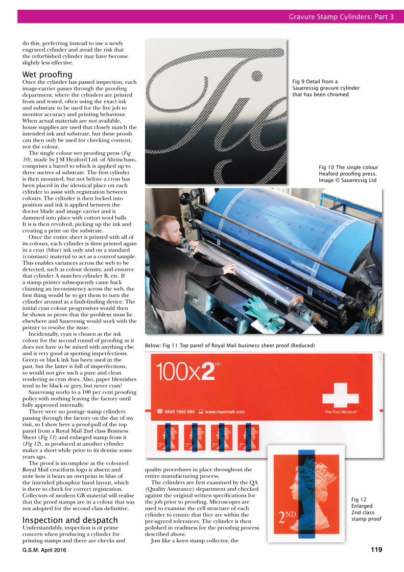
There were no postage stamp cylinders passing through the factory on the day of my visit, so I show here a proof-pull of the top panel from a Royal Mail 2nd class Business Sheet (Fig 11) and enlarged stamp from it (Fig 12), as produced at another cylinder maker a short while prior to its demise some years ago.
The proof is incomplete as the coloured Royal Mail cruciform logo is absent and note how it bears an overprint in blue of the intended phosphor band layout, which is there to check for correct registration. Collectors of modern GB material will realise that the proof stamps are in a colour that was not adopted for the second class definitive.
Inspection and despatchUnderstandably, inspection is of prime concern when producing a cylinder for printing stamps and there are checks and
quality procedures in place throughout the entire manufacturing process.
The cylinders are first examined by the QA (Quality Assurance) department and checked against the original written specifications for the job prior to proofing. Microscopes are used to examine the cell structure of each cylinder to ensure that they are within the pre-agreed tolerances. The cylinder is then polished in readiness for the proofing process described above.
Just like a keen stamp collector, the
Fig 9 Detail from a Saueressig gravure cylinder that has been chromed
Below: Fig 11 Top panel of Royal Mail business sheet proof (Reduced)
Fig 12 Enlarged 2nd class stamp proof
G.S.M. April 2016
Gravure Stamp Cylinders: Part 3
120
Further readingThere are innumerable articles and books on the subject covered in this article. A selection that proved especially useful as background reading are recorded here.
Blaney, Henry R, Photogravure (Scovill and Adams Co, USA, 1895)—non-philatelic.
Cartwright, H Mills, Notes on the rotary photogravure process (Autotype Co Ltd, GB, undated but probably 1940)—non-philatelic.
Conlon, James A, ‘Growth of gravure in postage stamps—Parts one and two’, Philateli-Graphics, October 1982 and January 1983.
Ellis, Howard. ‘Printing processes: photogravure’, Stamp and Coin Mart, December 1990.
Harrison & Sons, Postage stamps/photogravure brochure, c.1967.
Harrison & Sons, Postage stamps leafl et, c.1967.
Harrison & Sons. ‘How photogravure stamps are made’, Printing World. Reprinted in Stamp Collecting, 3 February 1967.
Harrison & Sons, Security printers for the world brochure, c.1981.
Jessop, Philip. ‘A new look at the Elizabethan specials’, Gibbons Stamp Monthly, September 1974.
Lilien, Otto M, History of industrial gravure printing up to 1920, (Lund Humphries, 1972).
Mackay, James, ‘The introduction of photogravure’, Gibbons Stamp Monthly, September 1993
Mackay, James, ‘The introduction of photogravure’, British Philatelic Bulletin, August 2004.
Mackay, James, ‘The fi rst photogravure issues’, British Philatelic Bulletin, September 2004.
Melville, Fred J, ‘The photogravure process—Parts one and two’, Gibbons Stamp Monthly, May and June 1935.
Morgan, Glenn H, ‘75 years of British stamps by photogravure’, British Philatelic Bulletin, August 2009.
Morgan, Glenn H, ‘Stamp production: gravure’, Royal Mail Stamps and Collectables, 2007— web article.
Ray, Leslie R and Rogers-Tillstone, B, Background to Philately: An anthology (Blandford Press, 1953)—includes article by Sir B Guy Harrison from 1932 entitled ‘The photogravure process as applied to postage stamp printing’.
Robinson, Barry, ‘How stamps are printed by the photogravure method’, British Philatelic Bulletin, January 1989.
Rosenblum, Larry. ‘Great Britain celebrates 75 years of multicolor photogravure stamps’, Scott Stamp Monthly, February 2010.
Williams, L N & M, ‘Gravure printing methods’, Stamp Weekly, 4 January 1968.
AcknowledgementsMy thanks are offered to Brian Janes, ex-Post Offi ce Director at Harrison & Sons, who kindly verifi ed information contained in Part 1. Special thanks also go to John Gilmour, Managing Director of Saueressig UK, for agreeing to my visit and to Allan Blundell, Technical Director, for acting as host during the factory tour. They both have an intimate knowledge of gravure cylinder production, with 27 years and 18 years involvement respectively, and made valuable observations regarding the draft of Parts 2 and 3. Their co-workers, Adam Evans and Bryn Hillier, likewise merit a mention for their considerable assistance in answering the many questions posed during my visit.
Thanks also to Royal Mail Group Ltd, De La Rue plc and International Security Printers Ltd for authorising the tour. Philatelists Ian de la Rue Browne, Graham Eyre and Richard West accompanied me to Saueressig and contributed to the collective philatelic knowledge shared within this article.
Saueressig team then look for cylinder fl aws when carrying out their checks, but with a view to eradicating them before they reach a Post Offi ce.
After all checks have been made, a QA Report is produced on every cylinder confi rming that all aspects are accurate, including details of the cells under a microscope, screen used, depth of the cells, angle of the stylus, channel between cells, surface roughness, etc. Nothing is left to chance and if a problem is highlighted, instructions will be issued for a re-make of the cylinder if it does not reach the high-standards expected by Saueressig and its clients.
Once the proofi ng exercise and QA aspects are deemed accurate, the cylinder is securely wrapped, crated and shipped ready for use by current Royal Mail printers De La Rue or ISP.
Future advances Advances in laser technology, including Pico Laser for micro-print and text-in-text (Fig 13) features, are set to take security printing to the next level.
These technologies have yet to be used on postage stamps, but may well be a common element of stamp production one day in order to offer the latest security protection and to remain one step ahead of the counterfeiter.
A � nal wordWith the falling use of stamps and ever-smaller print runs, gravure and its stranglehold on British, indeed worldwide, stamp production has been broken by the offset process. A combination of sheet-fed and web-fed gravure printing had been the mainstream process for British defi nitive stamp production since 1934, but offset is now increasingly used, especially for the printing of commemorative stamps. This change is due to the improved quality now achievable by offset and the lower cost of printing by that process.
Looking through recent stamp new issue pages of GSM, it becomes clear that very few
countries now utilise gravure for stamp printing, with People’s Republic of China, Italy, Japan, South Korea and USA being some of the major countries outside of the UK who still regularly use this method. Only time will tell the extent to which gravure will continue to be used by Royal Mail.
While intaglio and letterpress are employed far less frequently these days, they are both still periodically in use and I suspect that gravure will also continue to be utilised for stamp production for many years to come and, if so, then no company is more capable of meeting printing cylinder needs better than Saueressig. Indeed, Royal Mail is clearly impressed with its cylinder maker, as the Artwork Manager, Stamps and Collectibles, stated on the pre-Saueressig website:
‘Apex Cylinders has always provided us with an outstanding service, both in terms of the quality demanded and the very tight deadlines involved. We have been very impressed with them indeed, to say the
least, as the work itself is quite demanding, particularly due to the security requirements of working with stamps.’
Saueressig UK is not reliant on offering its studio and its cylinder making facilities to Royal Mail as a means of remaining viable as a company thanks to the diverse categories of client that it works with. That said, the prestige attached to producing such crucial components of the stamp production process cannot be underestimated. When talking to staff throughout the factory, it was apparent that they were all extremely proud of their involvement with helping to create British postage stamps.