Page 1
Alvarenga, Handal, Recinos GRC. Transactions Volume 32. 2008. October 2008. Draft
1
SOLAR STEAM BOOSTER IN THE AHUACHAPÁN GEOTHERMAL FIELD Alvarenga Y., Handal S., Recinos, M.
LaGeo, S.A. de C.V. El Salvador, Central América
Keywords: Ahuachapán Geothermal Field, Direct Solar Radiation, Heat Exchanger, Heat
Transfer Fluid, Pyrheliometer, Steam Generator, Solar Collectors, Solar Field, Solar Steam
Booster, Thermosolar-Geothermal Hybrid System
Abstract A thermosolar R&D project of 2 phases, sponsored by LaGeo, started in 2007. The first
phase was presented in the GRC 2007, developing the solar to thermal conversion. The
second phase, boosting geothermal power, is described in this paper.
By concentrating solar energy into a prototype array of parabolic mirrors, dry steam has
been gained from separated geothermal water at well head conditions in the Ahuachapán
geothermal field. A 160m2 thermosolar-geothermal hybrid system has produced 0.1 Kg/s
of steam, with 99.8% quality at 4.4 bar-g and 154°C well head conditions. A solar field
300m x 400m size, running from 9 a.m. to 5 p.m., could produce 5.8 kg/s of steam,
equivalent to 2.5 MWe from a turbine 4.4 bar-g inlet steam pressure.
Introduction
The constant increment in the demand of energy and the high prices of fuels as well as the
air pollution due to greenhouse gasses are enough reasons to move on the exploitation of
renewable and non-conventional energy sources. These untapped energy sources such as
geothermal, solar, wind, hydro, etc. are simply the energies of the future. Consequently,
LaGeo has acquired the commitment of researching and developing projects focusing on
non-conventional energy sources with emphasis in the exploitation of solar energy because
of the high solar radiation available in El Salvador. By installing a commercial
thermosolar-geothermal hybrid system it is possible to boost the output power of the
current geothermal facilities.
This paper summarizes the process of gaining steam by operating a prototype, consisting of
a couple of Solar Collectors (SC) and a steam generator, both developed in the
Ahuachapán geothermal field since March 2007. It is demonstrated that dry steam, able to
drive an available turbine, is produced by boiling separated geothermal liquid at a constant
pressure into the steam generator fed by a heat transfer fluid (HTF) heated by the SC. This
thermosolar-geothermal hybrid system can boost the current output power of any
geothermal facility located on the sun-belt region of the Earth.
The Ahuachapán Geothermal Field The Ahuachapán geothermal field is located in the western part of El Salvador, Central
America, and 100 Km apart from San Salvador, the capital city, as shown in figure 1. Due
to its low latitude, 13.9o N, this area receives considerable solar irradiation year round,
especially in the dry season, which goes from November to April. The average annual
direct solar energy received in this area is approximately 60% of the amount received in
Barstow, California1 and 95% of the amount received in Almería, Spain
2, where large
commercial solar power plants are being built.
Page 2
Alvarenga, Handal, Recinos GRC. Transactions Volume 32. 2008. October 2008. Draft
2
The reservoir temperature in the main exploitation area is 225°C. For most of the wells,
mixed fluids at well head conditions are 4-7 barg, 154-160°C and 15-20% of mass steam
fraction. Mass flow production averages 45 and 10 kg/s of water and steam, respectively.
Ahuachapán geothermal field is a double flash system. First fluid separation is in the range
4-7 barg medium pressure (MP) and steam factor consumption is 2.3 Kg.s-1
/MWe. Liquid
separated flashes into a boiler system at 0.6 barg low pressure (LP) and 8.8% separation
efficiency. Consumption factor for LP steam is 4.2 Kg.s-1
/MWe. Current gross and net
generations are 83 MWe and 77 MWe. Approximately 593 kg/s of water leaving the
flashers are pumped at 8.6 barg and reinjected into a neighbor field (Chipilapa) located 5
km away of the reservoir to avoid cooling effects and sustain a reservoir pressure above 18
bar. Besides, 50 kg/s of waste water (condensed steam from cooling tower) is pumped and
reinjected into Chipilapa area3.
Figure 1. Location of the Ahuachapán geothermal field
The Pilot Thermosolar Project The pilot thermosolar project is located at the platform of the AH-6 geothermal well. The
cyclonic separator of this well (see figure 2) operates at medium pressure of 4.6 barg (67
psig) and 154 oC, producing 2.8 Kg/s of separated water and 9.1 Kg/s of steam. The steam
is conducted to the medium pressure steam turbines. The separated water travels to the
flasher tanks, where the pressure falls down until a lower pressure of 0.6 barg, producing
0.24 Kg/s of steam. This steam is sent to the low pressure steam turbines, while the
residual water at 115 oC is pumped to re-injection wells.
Page 3
Alvarenga, Handal, Recinos GRC. Transactions Volume 32. 2008. October 2008. Draft
3
Figure 2.The AH-6 well connections
The Pilot thermosolar project consists of two SC, which concentrate the solar irradiation
into an absorber pipe due to both its parabolic shape and solar tracking system. As shown
in figure 3, the irradiation is concentrated in the linear focus of the parabola provided that
it is well positioned towards the solar disc. The solar tracking system positions the SC to
the appropriate angle from 8 a.m. to 4 p.m. period of time with higher solar irradiation.
Design and construction of all the system, including solar tracker system, was done locally,
even though there are several companies that offer these services, like FLABEG, Solel,
Schott, Solar Millennium, etc.
Figure 3.Picture and optical working principle of the SC.
Page 4
Alvarenga, Handal, Recinos GRC. Transactions Volume 32. 2008. October 2008. Draft
4
The solar field is compounded by the 2 SC, which are 4m wide and 20m long each one,
with 160m2 of solar receiving area. The purpose of the solar field is to heat a HTF that
circulates through the absorber pipe. This HTF is thermal oil called Therminol 55, which
can reach up to 290°C as a maximum working temperature without any degradation4.
Figure 4 sketches circulation of HTF through the SC and storage in the so-called “Hot
Tank”. As the HTF circulates in the absorber pipe, it gains heat and increases temperature.
The HTF, which is total 1200 Kg, is re-circulated into the system at 1.5 kg/s mass flow
until it reaches 225°C, the minimum working temperature of the steam generator (SG).
Figure 4. The HTF hydraulic circuit.
A daily typical chart performance of the SC is shown in figure 5. The upper graph shows
the direct solar irradiation measured by a pyrheliometer installed in the site. In some
periods the irradiation is almost zero because of the presence of clouds. The middle graph
shows the temperature of the HTF. The initial temperature of the HTF storaged in the hot
tank was 100°C. The temperature increment is linear during periods of maximum
irradiation. The rate of temperature increment declines when direct irradiation is disturbed
by presence of clouds. In the latest period of the day, when the temperature is the highest,
the trends temperature becomes flat because of higher thermal losses to the environment
occurred there. Finally, the lower graphs show the output thermal power given by the SC
and the efficiency of the conversion solar radiation to heat. It is noticed that both curves
are parallel each other and the efficiency lowers as the HTF temperature increases.
Page 5
Alvarenga, Handal, Recinos GRC. Transactions Volume 32. 2008. October 2008. Draft
5
Figure 5. Performance of the pilot solar project during a common day
Thermosolar System and Geothermal Field Interaction
As can be seen in figure 6 there are two possibilities to combine the thermosolar and
geothermal energies to boost the current geothermal power plant.
The first option considers installing the SG in the separated water line between the
cyclonic separator and the flasher system. A fraction of the geothermal liquid boils in the
SG and the generated steam can be sent to the medium pressure steam line. The residual
water that does not boil is sent to the current flasher tanks.
The second option installs the SG in the output line of water at 115 oC leaving the flasher
tanks. A fraction of the water entering into the SG boils to produce low pressure steam,
which can be sent to the current low pressure steam line. The residual water continues to
the reinjection line.
Figure 6. Options considered for interfacing the solar and the geothermal plant.
Page 6
Alvarenga, Handal, Recinos GRC. Transactions Volume 32. 2008. October 2008. Draft
6
To date the first option, which produces steam at medium pressure has been successful
tested. When the HTF, stored in the hot tank, reaches the minimum working temperature,
both separated geothermal water and HTF are pumped to the SG. Figure 3 suggests the
heat transfer between both fluids inside the SG. A mass flow of 1 Kg/s of separated liquid
enters to the SG and 1.8 Kg/s goes to the flasher system. Approximately 10% of the
geothermal water boils into steam at 4.4 barg and 154 oC. The residual water, leaving the
SG at the same inlet conditions travels to the current re-injection system. The outing cold
HTF is stored into another tank called cold tank.
Figure 7 shows a scheme of the SG, where the HTF and geothermal liquid flows exchange
heat. A flow of 1.5 Kg/s of HTF is pumped at 25 psig to the hot tubes. The HTF inlet and
outlet temperatures are 225 °C and 175 °C, respectively, while the pressure drop in the oil
circuit is 10 psig. On the other side, geothermal saturated water floods the hot tubes inside
the shell and gains heat from the HTF. Steam is produced at 4.4 barg (64 psig) and 154 oC;
which are the same conditions for the inlet and outlet geothermal brine.
Figure 7. Sketch of the Shell and Tubes SG used in the pilot project
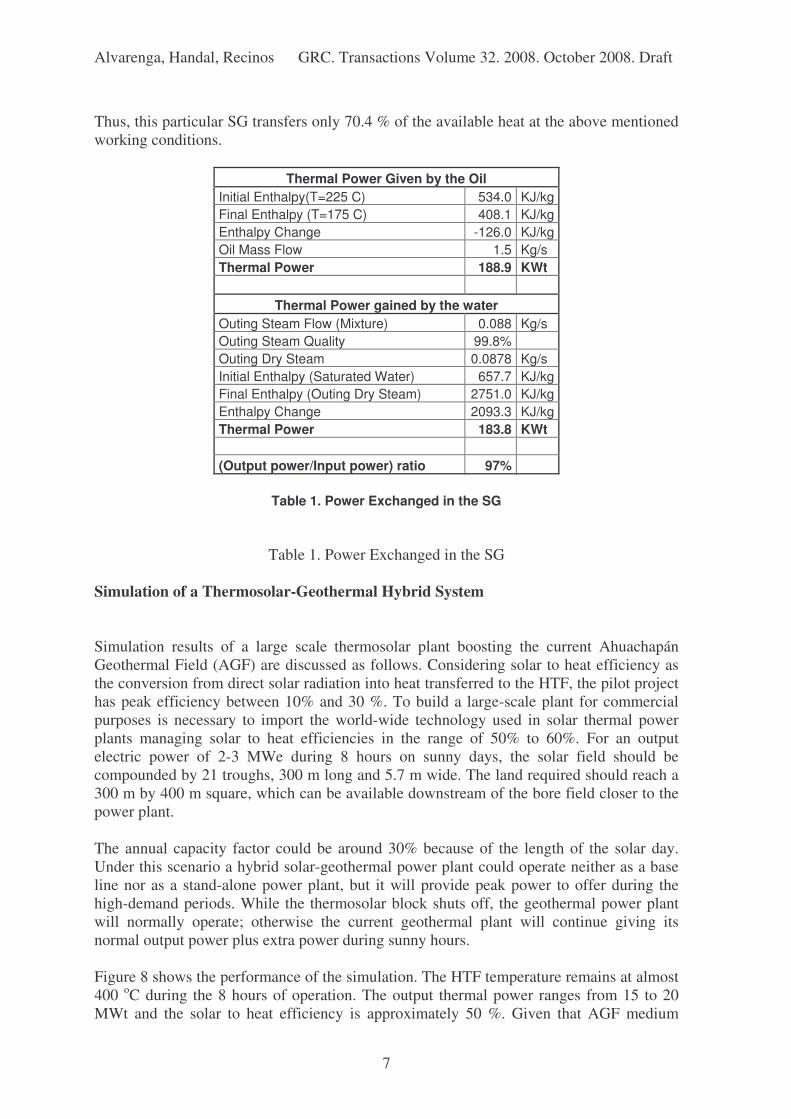
Table 1 shows some results of the heat exchange process between the two fluids. 97% of
the heat lost by the HTF is gained by the water, which means that heat losses to the
environment are only 3%. Chlorides and total dissolved solids chemical analysis indicate
99.8% quality for the generated steam.
Computing the Steam Generator Thermal Efficiency (SGTE) defined as:
inin
outin
waterHTF
HTFHTF
TT
TTSGTE
−
−
=
Gives:
154225
175225
−
−=SGTE
Page 7
Alvarenga, Handal, Recinos GRC. Transactions Volume 32. 2008. October 2008. Draft
7
Thus, this particular SG transfers only 70.4 % of the available heat at the above mentioned
working conditions.
Thermal Power Given by the Oil
Initial Enthalpy(T=225 C) 534.0 KJ/kg
Final Enthalpy (T=175 C) 408.1 KJ/kg
Enthalpy Change -126.0 KJ/kg
Oil Mass Flow 1.5 Kg/s
Thermal Power 188.9 KWt
Thermal Power gained by the water
Outing Steam Flow (Mixture) 0.088 Kg/s
Outing Steam Quality 99.8%
Outing Dry Steam 0.0878 Kg/s
Initial Enthalpy (Saturated Water) 657.7 KJ/kg
Final Enthalpy (Outing Dry Steam) 2751.0 KJ/kg
Enthalpy Change 2093.3 KJ/kg
Thermal Power 183.8 KWt
(Output power/Input power) ratio 97%
Table 1. Power Exchanged in the SG
Table 1. Power Exchanged in the SG
Simulation of a Thermosolar-Geothermal Hybrid System Simulation results of a large scale thermosolar plant boosting the current Ahuachapán
Geothermal Field (AGF) are discussed as follows. Considering solar to heat efficiency as
the conversion from direct solar radiation into heat transferred to the HTF, the pilot project
has peak efficiency between 10% and 30 %. To build a large-scale plant for commercial
purposes is necessary to import the world-wide technology used in solar thermal power
plants managing solar to heat efficiencies in the range of 50% to 60%. For an output
electric power of 2-3 MWe during 8 hours on sunny days, the solar field should be
compounded by 21 troughs, 300 m long and 5.7 m wide. The land required should reach a
300 m by 400 m square, which can be available downstream of the bore field closer to the
power plant.
The annual capacity factor could be around 30% because of the length of the solar day.
Under this scenario a hybrid solar-geothermal power plant could operate neither as a base
line nor as a stand-alone power plant, but it will provide peak power to offer during the
high-demand periods. While the thermosolar block shuts off, the geothermal power plant
will normally operate; otherwise the current geothermal plant will continue giving its
normal output power plus extra power during sunny hours.
Figure 8 shows the performance of the simulation. The HTF temperature remains at almost
400 oC during the 8 hours of operation. The output thermal power ranges from 15 to 20
MWt and the solar to heat efficiency is approximately 50 %. Given that AGF medium
Page 8
Alvarenga, Handal, Recinos GRC. Transactions Volume 32. 2008. October 2008. Draft
8
pressure turbines consumes 2.3 Kg.s-1
/MWe, the output power behaves as shown in the
lower graph of figure 8, equivalent to 20 MWh/day.
Figure 8. Performance of the Thermosolar-Geothermal Hybrid System
Conclusions
Based on the testing results of this pilot project, local solar radiation measurements,
reliable information from solar devices manufacturers and solar power plants developer
companies, it is possible to draw the following conclusions:
• The Solar Steam Booster located in the AGF built with local technology is
technically feasible, even though the measured efficiency is a third of the
efficiencies reported by thermosolar plants currently operating at commercial scale.
• The HTF temperature measured in the SC outlet is considerably higher than the
geothermal fluids temperatures available on the AGF wellheads.
• Solar field efficiency significantly decreases when HTF temperature is higher than
225 oC. This boundary temperature is enough to boost power to the current
geothermal power plant.
• The solar power booster will positively shift the geothermal power base line up to 8
hours/day.
• The implementation of a commercial large-scale thermosolar-geothermal hybrid
system in the AGF should cost lower than a pure thermosolar power plant because
the power block and the gathering fluid system are already available. The
investment should be focused on importing high-tech solar field and heat exchanger
equipments further than local technology because of their efficiency differences.
Page 9
Alvarenga, Handal, Recinos GRC. Transactions Volume 32. 2008. October 2008. Draft
9
Acknowledgments We would like to recognize to LaGeo´s Managers and Board of Directors the advanced
decision to allow developing this research. Special thanks to the AGF’s crew, technical and
administrative staff for their logistic support and ideas to carry out several tests.
References
1. US Department of Energy, Energy Efficiency and Renewable Energy, Solar
Parabolic Trough, p.14. Available from internet:
http://www1.eere.energy.gov/ba/pba/pdfs/solar_trough.pdf
2. Geyer, Michael, Potential of Solar Trough Installations in Europe, Solar
Millennium Group, p. 14. Available from internet:
http://www.ec.europa.eu/energy/res/events/doc/geyer_andasol.pdf
3. Handal, Salvador., Y. Alvarenga., M. Recinos, 2007. Geothermal Steam Production
by Solar Energy. Geothermal Resources Council Transactions. V. 31, p. 503-510
4. Solutia. 2005. Therminol 55, Efficient Reliable, Synthetic Heat Transfer Fluid.
http://www.therminol.com