Page i of ii Greater Crossbow Area Plan of Development, September 2014 – Not for Public Distribution GREATER CROSSBOW OIL AND GAS EXPLORATION AND DEVELOPMENT PROJECT DRAFT PLAN OF DEVELOPMENT September 2014 Prepared for Bureau of Land Management Buffalo Field Office Submitted by EOG Resources, Inc.
Transcript
Page i of ii
Greater Crossbow Area Plan of Development, September 2014 – Not for Public Distribution
GREATER CROSSBOW OIL AND GAS
EXPLORATION AND DEVELOPMENT PROJECT
DRAFT PLAN OF DEVELOPMENT
September 2014
Prepared for Bureau of Land Management Buffalo Field Office
Submitted by EOG Resources, Inc.
Page ii
Greater Crossbow Area Plan of Development, September 2014 – Not for Public Distribution
Greater Crossbow Area Plan of Development, September 2014 – Not for Public Distribution
1 INTRODUCTION
In 2013, EOG Resources, Inc. (EOG) approached the Bureau of Land Management (BLM)
Buffalo Field Office about preparing an Environmental Impact Statement (EIS) for proposed oil
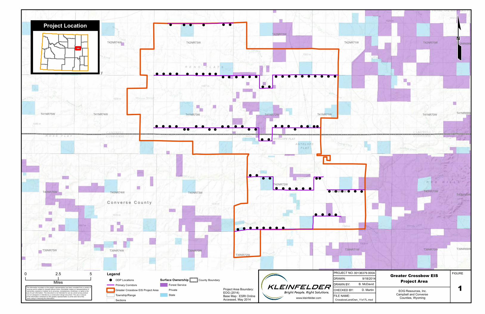
and gas exploration and development within the Greater Crossbow Area (Figure 1) in Campbell
and Converse Counties, Wyoming (hereinafter referred to as the Greater Crossbow Project
Area, Project Area, or PA).
EOG is proposing an innovative “spine and rib” approach that would maximize the use of multi-
well pads (i.e., the ribs) that are strategically placed along well-planned, primary corridor
systems that would include pipelines for oil, natural gas, condensate, and water, as well as
utility lines (i.e., the spines). The spine and rib design of the Greater Crossbow Plan of
Development (PoD) (hereinafter referred to as the Greater Crossbow PoD or Greater Crossbow
Project) is intended to reduce surface disturbance, habitat fragmentation, truck traffic, and air
emissions compared to that of a traditional oil and gas field development project. EOG’s
proposed design would result in reduced impacts for multiple, potentially affected resources.
Key features of the Greater Crossbow PoD include the following:
Development of an average of approximately 150 oil and natural gas wells per year over
10 years1, for 1,500 total oil and natural gas wells.
Construction of up to 100 optimized development well pads (ODP).
Two ODPs per section.
o An individual ODP could host between 1 and 22 wells. For analysis purposes it
is assumed that each ODP would host an average of 15 wells.
Drilling of numerous formations per pad. Each ODP would be designed for
simultaneous operations; EOG would be able to drill, complete, and produce multiple
wells at the same time on the same pad.
1 Drilling is planned over a 10‐year period; however, market conditions would dictate the length of the drilling phase and the number of wells drilled per year.
Page 2
Greater Crossbow Area Plan of Development, September 2014 – Not for Public Distribution
A primary corridor system to include pipelines for oil, gas, condensate, and water, as
well as utility lines, which would substantially reduce truck traffic.
Phased electrification of production equipment to reduce air emissions.
1.1 PROJECT LOCATION AND BACKGROUND
Project Location
The Greater Crossbow Project Area is located in the southern extent of the Powder River Basin
(PRB) and includes portions of southern Campbell and northern Converse counties in northeast
Wyoming. The Project Area is between Wright and Bill, WY, and encompasses all or portions of
ten townships including T42N:R74W - T42N:R71W, T41N:R74W – T41N:R71W, T40N:R72W –
T40N:R71W, and T39N:R72W.
Elevations within the Greater Crossbow Project Area range from approximately 4,500 to 5,500
feet above mean sea level. The Project Area falls within the Powder River Basin and Great
Plains physiographic provinces and is located within the Antelope Creek drainage system. The
area has historically been and is currently used for livestock grazing, oil and gas development,
coal mining, wildlife habitat, and recreation. This area provides summer and fall grazing for
cattle, sheep, and horses.
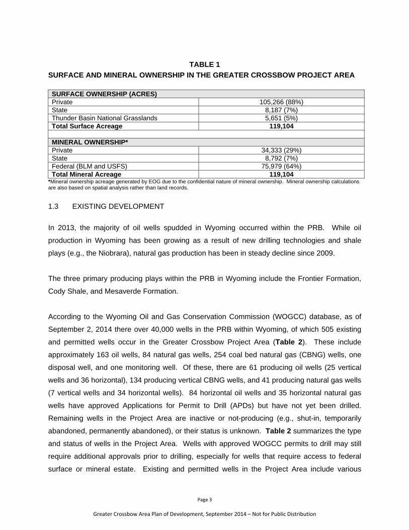
1.2 SURFACE AND MINERAL OWNERSHIP
The approximately 119,104 surface acres of the Project Area (PA) includes about 105,266
acres of privately owned lands (88% of the PA), 8,187 acres (7% of the PA) of State surface
administered by the State of Wyoming, and 5,651 acres (5% of the PA) of federal lands
managed by the U.S. Forest Service (USFS) Thunder Basin National Grasslands (TBNG).
Surface and mineral ownership is summarized in Table 1. Of note, there is no BLM-
administered surface within the Project Area.
Page 3
Greater Crossbow Area Plan of Development, September 2014 – Not for Public Distribution
TABLE 1 SURFACE AND MINERAL OWNERSHIP IN THE GREATER CROSSBOW PROJECT AREA SURFACE OWNERSHIP (ACRES) Private 105,266 (88%) State 8,187 (7%) Thunder Basin National Grasslands 5,651 (5%) Total Surface Acreage 119,104 MINERAL OWNERSHIP* Private 34,333 (29%) State 8,792 (7%) Federal (BLM and USFS) 75,979 (64%) Total Mineral Acreage 119,104
*Mineral ownership acreage generated by EOG due to the confidential nature of mineral ownership. Mineral ownership calculations are also based on spatial analysis rather than land records.
1.3 EXISTING DEVELOPMENT
In 2013, the majority of oil wells spudded in Wyoming occurred within the PRB. While oil
production in Wyoming has been growing as a result of new drilling technologies and shale
plays (e.g., the Niobrara), natural gas production has been in steady decline since 2009.
The three primary producing plays within the PRB in Wyoming include the Frontier Formation,
Cody Shale, and Mesaverde Formation.
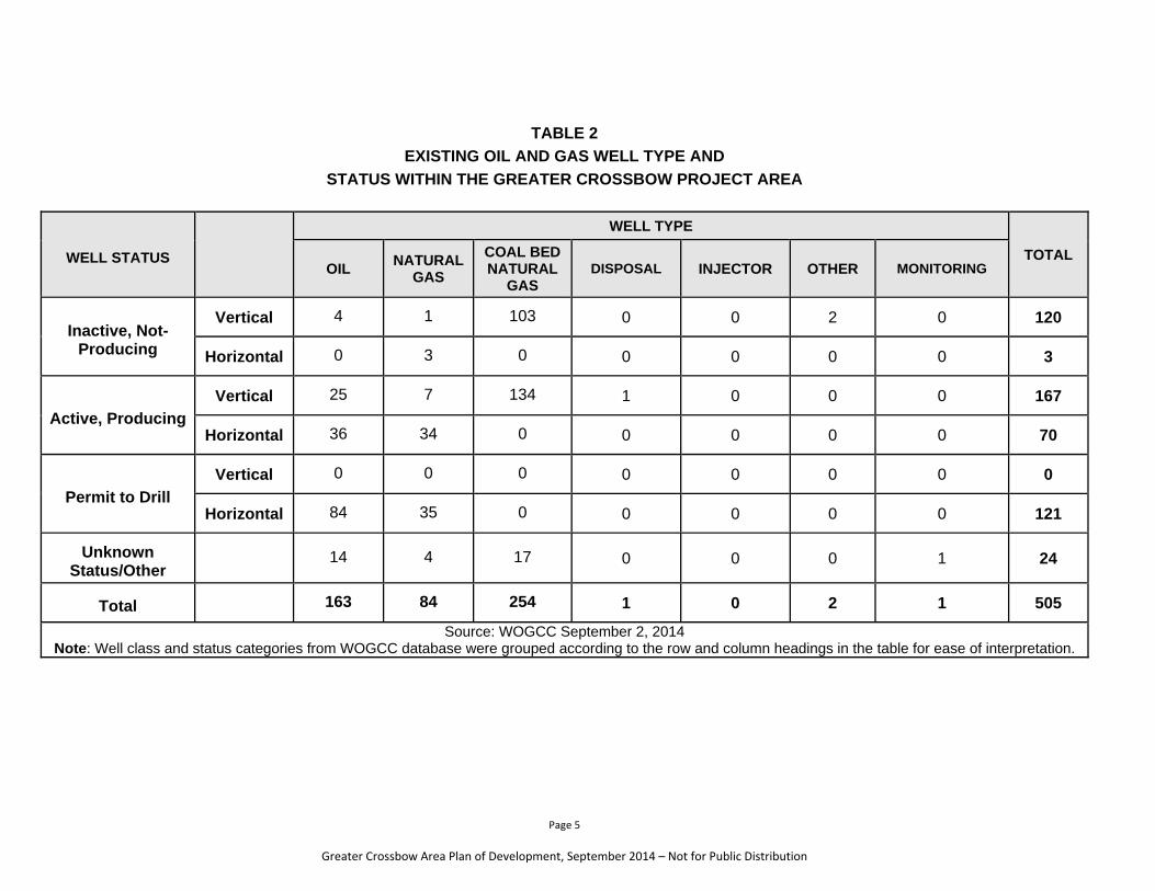
According to the Wyoming Oil and Gas Conservation Commission (WOGCC) database, as of
September 2, 2014 there over 40,000 wells in the PRB within Wyoming, of which 505 existing
and permitted wells occur in the Greater Crossbow Project Area (Table 2). These include
approximately 163 oil wells, 84 natural gas wells, 254 coal bed natural gas (CBNG) wells, one
disposal well, and one monitoring well. Of these, there are 61 producing oil wells (25 vertical
wells and 36 horizontal), 134 producing vertical CBNG wells, and 41 producing natural gas wells
(7 vertical wells and 34 horizontal wells). 84 horizontal oil wells and 35 horizontal natural gas
wells have approved Applications for Permit to Drill (APDs) but have not yet been drilled.
Remaining wells in the Project Area are inactive or not-producing (e.g., shut-in, temporarily
abandoned, permanently abandoned), or their status is unknown. Table 2 summarizes the type
and status of wells in the Project Area. Wells with approved WOGCC permits to drill may still
require additional approvals prior to drilling, especially for wells that require access to federal
surface or mineral estate. Existing and permitted wells in the Project Area include various
Page 4
Greater Crossbow Area Plan of Development, September 2014 – Not for Public Distribution
combinations of federal, state, and private ownership of mineral and surface estate. EOG is the
operator for 102of the producing wells in the Project Area.
1.3 INTERIM DEVELOPMENT
EOG is proposing an interim drilling program that will allow wells to be drilled during the
preparation of the EIS. Interim drilling will include wells for which APDs have already been
secured, wells for which approved APDs are pending, and new wells for which APDs will be
submitted. The BLM will prepare site-specific NEPA analyses to support EOG’s interim drilling
plans. Interim drilling will help EOG to define the reservoir geology in the Greater Crossbow
area, and will consequently allow them to refine ODP locations.
Page 5
Greater Crossbow Area Plan of Development, September 2014 – Not for Public Distribution
TABLE 2
EXISTING OIL AND GAS WELL TYPE AND STATUS WITHIN THE GREATER CROSSBOW PROJECT AREA
WELL STATUS
WELL TYPE
TOTAL OIL NATURAL
GAS
COAL BED NATURAL
GAS DISPOSAL INJECTOR OTHER MONITORING
Inactive, Not-Producing
Vertical 4 1 103 0 0 2 0 120
Horizontal 0 3 0 0 0 0 0 3
Active, Producing Vertical 25 7 134 1 0 0 0 167
Horizontal 36 34 0 0 0 0 0 70
Permit to Drill Vertical 0 0 0 0 0 0 0 0
Horizontal 84 35 0 0 0 0 0 121
Unknown Status/Other
14 4 17 0 0 0 1 24
Total 163 84 254 1 0 2 1 505
Source: WOGCC September 2, 2014 Note: Well class and status categories from WOGCC database were grouped according to the row and column headings in the table for ease of interpretation.
Page 6
Greater Crossbow Area Plan of Development, September 2014 – Not for Public Distribution
1.4 EOG RESOURCES, INC.
EOG is one of the largest independent (non-integrated) crude oil and natural gas companies in
the United States with proved reserves in the United States, Canada, Trinidad, the United
Kingdom, and China. As of December 31, 2013, EOG’s total estimated net proved reserves
were 2,119 million barrels of oil equivalent (MMBoe). Approximately 94 percent of these
reserves were located in the United States. EOG’s total company production in 2013 was 186.2
MMBoe. Approximately 88 percent of the company’s 2013 total production was in the United
States and Canada.
1.5 PURPOSE AND NEED
The purpose of the project is to allow EOG to develop, produce, and market oil, gas
condensate, and associated hydrocarbon products, pursuant to their rights and obligations
under existing oil and gas leases issued by the BLM. The need for exploration and
development of oil and gas resources is established by the BLM’s responsibility under the
Mineral Leasing Act of 1920 (30 United States Code [USC] 188 et seq.), as amended, to
promote the mining of oil and gas on the public domain. Deposits of oil and gas owned by the
United States are subject to disposition in the form and manner provided by the Mineral Leasing
Act. The BLM oil and gas leasing program encourages development of domestic oil and gas
reserves, consistent with the BLM’s multiple-use mission. The oil and gas resources produced
from the Greater Crossbow project are needed to meet national domestic energy demand.
Page 7
Greater Crossbow Area Plan of Development, September 2014 – Not for Public Distribution
2 PLAN OF DEVELOPMENT
The following sections describe EOG’s PoD for the Greater Crossbow Project Area. As noted in
several sections of the PoD, EOG has made a good faith, preliminary attempt to identify
conceptual locations for most of the proposed ODPs. Site-specific locations would be
developed following the Record of Decision (ROD) for the EIS and in coordination with the
private surface landowners and relevant agency stakeholders.
2.1 TARGET FORMATIONS AND SUBSURFACE SPACING
The Greater Crossbow Project includes both exploration and field development in that during
Phase I of the project exploratory wells would be drilled to define the reservoir geology. Phase
II development wells would be drilled where the reservoir has been defined. EOG is currently
focusing on exploration of the Parkman, Turner, Mowry, Niobrara, and Muddy Formations;
however, other potential geologic formations may also be identified as the exploratory wells are
drilled. While this phased approach would be utilized as feasible, the exploratory nature of a
portion of the drilling makes it difficult to precisely predict the drilling plan.
Subsurface well spacing is largely a function of reservoir geometry, i.e., the area of the
producing formation that can be effectively and economically drained of oil and gas resources
by a single wellbore. Sub-surface spacing for the Greater Crossbow Project would be
formation-specific and would depend on the results of exploratory drilling.
2.2 PROPOSED WELL COUNT
As previously stated, EOG is proposing to drill up to 1,500 oil and natural gas wells at an
average rate of approximately 150 wells per year. However, fewer wells may be drilled for the
following reasons:
Unforeseen variations in reservoir characteristics may result in re-evaluation of well
spacing in some parts of the Project Area.
Successful use of new technologies may allow production to be maintained at the
projected levels but with the use of fewer wellbores.
Economic factors (such as commodity prices) may affect EOG’s ability to drill wells.
Page 8
Greater Crossbow Area Plan of Development, September 2014 – Not for Public Distribution
Lease stipulations may prevent drilling a well in some areas.
2.3 PRE-CONSTRUCTION ACTIVITIES
Prior to surface disturbing activities, EOG would complete the following activities:
Contact surface owners in accordance with the Wyoming Surface Entry Act;
Perform biological, cultural resource, paleontological, and/or other surveys, as required
by the appropriate Surface Management Agency (SMA) and agreed upon by the
private surface owner.
Stake and survey each surface location, access road, and pipeline corridor;
Submit Notice(s) of Staking (NOS), APD, and USFS surface use authorization (SUA)
or surface use permit (SUP) or State of Wyoming (WY) temporary use permit (TUP) as
applicable, to the appropriate SMA;
Participate in onsite evaluations with private surface owners, WOGCC personnel, BLM,
and/or USFS;
Submit site-specific applications (e.g., Surface Use Plan of Operations [SUPO]) to the
appropriate SMA and modify them, as needed;
Submit detailed construction or engineering plans, as needed, to the appropriate SMA;
Collect four baseline water samples, if landowner access is granted, in accordance
with WOGCC rules and regulations, prior to the setting of the well conductor casing.
See Section 2.7.3 for additional information.
EOG would obtain required permits from the BLM, USFS, and/or WOGCC prior to initiating
surface disturbing activities on federal or State lands or minerals. To initiate the federal
permitting process, EOG would file an NOS and/or APDs to the BLM and/or State for each
proposed well. The agencies would process the applications to determine if they meet all
requirements and would subsequently notify EOG of dates, times, and places to meet and
conduct onsite inspections of the proposed locations.
Applications for Permit to Drill would be technically and administratively complete, and would
generally consist of a SUPO, 10-Point Drilling Plan, evidence of bond coverage, accompanying
information/exhibits/maps that might be required by the BLM, and a surface reclamation plan. A
SUPO would typically contain information describing construction operations, access road(s),
pipeline corridors (i.e., Secondary Corridors and associated Primary Corridors), water supply
Page 9
Greater Crossbow Area Plan of Development, September 2014 – Not for Public Distribution
and haul route, well site layout, production facilities, waste disposal, and restoration or
reclamation associated with the well development proposal. Applications for Permit to Drill for
the Greater Crossbow Project would, as appropriate, include information relative to other wells
already drilled from the proposed ODP. The drilling plan would generally include information
describing the technical drilling aspects of the specific proposal, including subsurface resource
protection. The BLM would determine the suitability of the proposed design, construction
techniques, and procedures during the APD review process.
2.4 CONSTRUCTION
Construction operations would conform to standards described in Surface Operating Standards
and Guidelines for Oil and Gas Exploration and Development ("Gold Book") (BLM and USFS
2007), lease stipulations, and EOG-committed project design features. On private lands,
construction operations would be completed in accordance with surface owner preferences.
Construction operations would generally occur during daylight hours. Anticipated surface
disturbance from construction activities is summarized in Section 2.4.5.
2.4.1 OPTIMIZED DEVELOPMENT PADS
Conceptual locations for 91 of the 100 proposed ODPs are illustrated on Figure 1. Following
completion of the ROD, site-specific locations for the ODPs would be determined in cooperation
with the private surface owner, State, USFS, and/or BLM. On private surface, the surface
owner would ultimately dictate placement of the ODP.
Construction of an ODP would typically entail the use of crawler tractors, motor graders, Class
125 or larger track hoes, backhoes, 10- to 20-yard dump trucks, and Class 988 loaders. ODP
construction equipment needs would vary depending on site-specific conditions.
ODPs would be constructed from the native soils and rock material present on site at each ODP
location. Topsoil and native vegetation would be stripped and stockpiled at the pad footprint.
The stockpiling of topsoil and stripped vegetation would allow for a seed bank that should assist
the re-establishment of existing vegetation. Locations would then be leveled by balancing cut
and fill areas to the maximum extent possible to create a flat and level workable surface for
drilling equipment while alleviating the need for imported materials. Compaction rates would be
in compliance with American Association of State Highway and Transportation Officials
Page 10
Greater Crossbow Area Plan of Development, September 2014 – Not for Public Distribution
(AASHTO) requirements. The fill section of the pad would be compacted to support the drilling
rig and any other heavy equipment. All cut and fill slopes needed for the ODP would be
constructed so that stability would be maintained for the life of the Project. Cut and fill slopes
would be designed to allow for the detention of topsoil and subsoil fill material.
Use of erosion control measures, including proper grading to minimize slopes, diversion
terraces and ditches, mulching, terracing, riprap, fiber matting, temporary sediment traps, and
broad-based drainage dips or low water crossings would be employed by EOG as necessary
and appropriate to minimize erosion and surface runoff during construction, drilling, and
production.
Construction materials required for surfacing the ODPs would be obtained from a contractor
having a permitted source of materials within the general area. Gravel for the ODPs would
typically be purchased from the Wright Pit located in Campbell County, Wyoming (Western
Sunset LLC); Strock Pit located in Converse County, Wyoming; Quality Agg & Construction
located in Campbell County, Wyoming; Collins Quarry located in Platte County, Wyoming; or
Energy Basin LLC, located in Johnson County, Wyoming.
ODPs would initially be constructed to an appropriate size depending on the number of wells
proposed for the location. On average, wells would require 1.8 acres of initial disturbance per
well. Following interim reclamation each well would require 1.4 acres of long-term disturbance.
Given that the maximum number of wells proposed for a single ODP is 22 wells, the largest
ODP proposed could be approximately 39 acres (1.8 acres of initial disturbance per well),
consisting of approximately 19.7 acres for drilling and 18.9 acres for production facilities.
Following interim reclamation a maximum-sized 22-well ODP would be reclaimed to
approximately 28 acres (or 1.4 acres of long-term disturbance per well). Because EOG has
proposed a total of 1,500 wells, in no event will all 100 ODPs be the maximum size of 22 wells
per pad. For the purposes of analysis, EOG suggests using an average of 15 wells per ODP
(1,500 wells divided by the maximum of 100 proposed ODPs). Total initial disturbance from
ODP construction is anticipated to be approximately 2,700 acres of initial disturbance.
Following interim reclamation, surface disturbance would be reduced to about 2,100 acres. The
exact size and configuration of individual ODPs will be analyzed when site-specific development
is proposed.
Page 11
Greater Crossbow Area Plan of Development, September 2014 – Not for Public Distribution
Compared to traditional oil and gas field development, EOG’s ODP proposal would result in a
substantial reduction of surface disturbance on a per well basis. For example, on average the
long-term disturbance area for a typical horizontal well pad in the PRB is about 7 acres per well,
which would equate to about 10,500 acres of long-term disturbance for 1,500 wells. Under the
ODP strategy, each well would occupy a long-term disturbance area of about 1.4 acres, which is
approximately an 80 percent reduction in per-well disturbance.
ODP construction would be supervised by a designated company representative who is familiar
with the terms and conditions in the Record of Decision (ROD) for the EIS and approved APDs,
as well as any specifications from private surface owners.
2.4.2 PIPELINE CORRIDORS
During the initial stage of the Greater Crossbow Project, water for drilling, oil, and produced
water would be trucked to and from locations. However, EOG’s ultimate goal is to substantially
reduce oil and water truck traffic through their proposed pipeline corridor system. Specifically,
EOG’s proposed pipeline and utility line system for the project includes the development of a
series of buried Primary Corridors that would consist of gathering lines, Secondary Corridors
that would connect buried flowlines from wells to the gathering lines, and cross-country
pipelines as needed. EOG’s Primary Corridors (gathering lines) would tie into existing sales
pipelines operated by DCP Midstream (DCP) and/or Anadarko Petroleum Corporation
(Anadarko). Additional detail on the Primary Corridors, Secondary Corridors, cross-country
pipelines, and construction methodology is provided below.
Primary Corridors
As illustrated on Figure 1, the Primary Corridors for gathering lines would generally trend in an
east-west direction along section lines. In certain areas, the corridors jog to the north or south
to accommodate private surface owner preference or to connect to an existing well pad.
Similarly, as onsites occur, the locations of Primary Corridors may also be adjusted to the north
or south to avoid sensitive natural resources such as raptor nests, cultural resources, streams,
or wetlands, etc., and/or to accommodate additional surface owner preferences.
As depicted in Figure 1, the strategic design of the Primary Corridors would result in a
substantial reduction in overall surface disturbance compared to that of a traditional oil and gas
Page 12
Greater Crossbow Area Plan of Development, September 2014 – Not for Public Distribution
field, where pipelines and access roads are constructed in a “spider web” fashion across an
entire project area. Instead, the locations of the Primary Corridors would result in substantial
areas of land that would be left relatively undisturbed by new oil and gas activity, which would
reduce overall disturbance and habitat fragmentation.
Primary corridors would include oil gathering pipe ranging from 6- to 10-inches outer diameter
(OD); high pressure gas gathering pipe ranging from 6- to 8-inches OD; low pressure gas
gathering pipe ranging from 10- to 14-inches OD; condensate pipe ranging from 4- to 8-inches
OD; and produced water pipe ranging from 6- to 10-inches OD. High pressure gas gathering
pipe would be constructed of steel. All other pipe would be constructed of either steel or high-
density polyethylene (HDPE). Based on the conceptual locations illustrated in Figure 1, there
would be about 57 miles of Primary Corridor in the Greater Crossbow Project Area. Initial
disturbance from construction of the Primary Corridors would be about 1,416 acres. Following
pipeline installation, the entire pipeline corridor would be reclaimed with the exception of a small
area (about 8 feet wide) that would be required for a two-track road needed for pipeline
maintenance for the life of the project. Therefore, long-term disturbance from the Primary
Corridors would be about 55 acres. TABLE 3 summarizes the types, sizes, and capacity of pipelines proposed within the Primary
Corridors.
TABLE 3
PIPELINES WITHIN PRIMARY CORRIDORS
LINEAR INFRASTRUCTURE OUTER
DIAMETER CONSTRUCTION
MATERIAL
CAPACITY (POUNDS PER SQUARE INCH
(PSI)) Oil Gathering Pipeline
6-10" Steel or HDPE 1000
High Pressure Gas Gathering Pipeline
6-8" Steel 1500
Low Pressure Gas Gathering Pipeline
10-14" Steel or HDPE 100
Condensate Pipeline
4-8" Steel or HDPE 1400
Produced Water Pipeline
6-10" Steel or HDPE 200
Water Supply Pipeline
6-12" Steel or HDPE 200
Page 13
Greater Crossbow Area Plan of Development, September 2014 – Not for Public Distribution
Secondary Corridors
Secondary Corridors would typically consist of a 200- to 400-foot long pipeline corridor designed
to connect oil, gas, condensate, produced water, and water supply flowlines from the wells on
an ODP to the larger diameter gathering lines in the Primary Corridors. Flowlines would range
from 3 to 6 inches OD. Flowlines would either be constructed of steel or HDPE. Based on an
average of a 250-foot long Secondary Corridor per ODP, there would be approximately 25,000
feet or about 5 miles of Secondary Corridor within the Greater Crossbow Project Area. Initial
disturbance from construction of the Secondary Corridors would be about 124 acres. Following
pipeline installation, the entire pipeline corridor would be reclaimed with the exception of a small
area (about 8 feet wide) that would be required for a two-track road needed for pipeline
maintenance for the life of the project. Therefore, long-term disturbance of the Secondary
Corridors would be about 5 acres.
Cross-Country Pipelines
In limited situations, for example to substantially reduce total pipeline length or where dictated
by the surface owner, a proposed pipeline corridor could be installed independent of the Primary
Corridors. Conceptual locations for cross-country pipelines are not illustrated on Figure 1. All
cross-country pipelines would be buried and would require a 205-foot construction width.
Cross-country pipelines would either be constructed of steel or HDPE. Cross-country pipelines
could total approximately 10 miles. Initial disturbance from construction of cross-country
pipelines would be about 248 acres. Following pipeline installation, the entire pipeline corridor
would be reclaimed with the exception of a small area (about 8 feet wide) that would be required
for a two-track road needed for pipeline maintenance for the life of the project. Therefore, long-
term disturbance of the cross-country pipelines would be about 10 acres.
Pipeline Construction Methodology
Pipeline construction methodology would be consistent amongst Primary, Secondary, and
cross-country pipeline corridors. The approved corridor, USFS SUA or SUP, or WY TUP would
be cleared using a grader. Scrub vegetation such as sagebrush, greasewood, grasses, etc.,
would be scalped and temporarily windrowed along the edge of the corridor. Scalping would
Page 14
Greater Crossbow Area Plan of Development, September 2014 – Not for Public Distribution
remove surface vegetation, while allowing the root systems to remain in place thereby reducing
potential erosion and allowing more successful reclamation.
Backhoes or trenching machines would then be used to excavate/ditch the pipeline trench. Soil
that is excavated during ditching operations would be temporarily stockpiled on the non-working
side of the trench. Trenches would not be left open longer than 48 hours if possible, and soft
plugs would be installed every ¼ mile when the trench is left open overnight.
Oil, gas, condensate, produced water, and water supply pipe would be strung along the trench
and fused or welded prior to being lowered into the trench. Specifically, individual joints of pipe
would be strung along the trench corridor adjacent to the excavated ditch and arranged so they
are accessible to construction personnel. All fused connections would then be visually
inspected, and all welded connections would be x-rayed. The pipe assembly would then be
lowered into the trench by side-boom tractors. Tracer wire would be installed in the ditch within
a 6-inch OD HDPE pipe, which would be used for future locating purposes. Each pipe would be
buried a minimum of 42 inches deep with the exception of areas where rock is encountered that
requires ripping or shooting. The different types of pipe would be spaced apart in accordance
with industry standard safety requirements.
Where pipelines are installed adjacent to access roads they would be installed at least 5 feet
from the edge of the road. Where proposed pipelines intersect paved roads, the road would be
bored under and the pipe would be pulled back through the bore. Pipelines would be buried at
least 5.5 feet deep under all roads.
Following installation of all proposed pipe material, the trench would be back-filled and packed
using backfilling or bladed equipment.
Pipeline construction activities would be confined within the approved pipeline corridor, USFS
SUA or SUP, or WY TUP. All pipeline construction activities would cease when soils or road
surfaces are frozen or become saturated to the extent that construction equipment is unable to
stay within the approved corridor and before activities cause irreparable harm to roads, soils, or
excessive siltation of nearby lakes, reservoirs, or live flowing streams. Sedimentation and
erosion control features along the pipeline corridors would be constructed as needed, in
Page 15
Greater Crossbow Area Plan of Development, September 2014 – Not for Public Distribution
accordance with Best Management Practices (BMPs) and a Storm Water Pollution Prevention
Plan (SWPPP).
Pipeline corridors would be constructed to an initial disturbance width of approximately 205 feet.
2.4.3 ACCESS ROADS
Primary access to the Project Area is from Highway 59 south of the Project Area by the towns of
Bill or Wright, Wyoming. As feasible and as authorized by the SMA or private surface owner,
new access roads would be constructed off existing well field and two-track ranch roads to
access each proposed ODP. However, most access roads would be located on private surface,
and due to private owner restrictions, access roads would not necessarily be constructed in-line
with the Primary Corridors. As such, locations for new access roads would generally be
dictated by the respective surface owner(s). Existing roads, upgraded roads, and newly built
roads would be maintained in the same or better condition than existed prior to EOG operations
and would meet the standards outlined in the Gold Book (BLM and USFS 2007). Roads would
be maintained until abandonment and reclamation of wells. Where roads are needed on federal
surface, EOG would obtain a USFS SUA or SUP, or WY TUP
Roads would be constructed in accordance with Gold Book standards (BLM and USFS 2007).
New roads would be completed as a single-lane, crowned, with an 18- to 22-foot-wide running
surface and 60 feet of subgrade. Turnouts would be installed as needed every 500 to 800 feet
for visibility depending on topography (e.g., blind curves), per Gold Book standards. Turnouts
would be approximately 24 feet wide and 40 to 60 feet long. Access roads would be constructed
with a 4:1 slope for ditches, and rip rap would be used along the slopes as needed for
stabilization. A minimum of 6 inches of topsoil would be stripped from new access roads prior to
any further construction activity. Stripped topsoil would be stored along the sides of the new
access roads and stabilized by seeding and/or matting, as appropriate.
Roads would be constructed with wing ditches and culverts installed as necessary to provide
proper drainage along the access road route. Sedimentation and erosion control features along
the access roads would be constructed as needed, in accordance with BMPs and a SWPPP. In
the event that commercial production is established from the subject wells, the access road
Page 16
Greater Crossbow Area Plan of Development, September 2014 – Not for Public Distribution
would be surfaced to an average minimum depth (after compaction) of 4 inches with 3-inch
minus pit run gravel or crushed rock, if required by the SMA or private surface owner.
Construction activity would not be conducted using frozen or saturated soils material or during
periods when watershed damage is likely to occur. If access roads are dry during construction,
drilling, and completion activities, water would be applied to the access roads to help facilitate
road compaction (during construction), provide dust abatement, and minimize soil loss as a
result of wind erosion.
As previously stated, locations for access roads have not yet been determined since ODP
locations have not been onsited, nor have permissions been secured by private surface owners.
However, about 95 miles of upgraded or new access roads are estimated to be needed. Where
agreed upon by the surface owners, new access roads would follow the Primary Corridors. As
such, the estimated length of access roads required was calculated based on the total length of
the proposed Primary Corridors (about 58 miles), plus an additional 30% (17 miles) where
landowners are anticipated to prohibit new access roads along the Primary Corridors, plus an
estimated 20 miles of north-south trending access roads that would be required to connect the
Primary Corridors. Average initial surface disturbance width for access roads would be
approximately 60 feet wide. Therefore, access road construction would result in the initial
disturbance of approximately 688 acres. Following interim reclamation, road corridor widths
would be reduced to 40 feet, resulting in long-term disturbance of approximately 459 acres.
2.4.4 WATER SOURCE WELLS
EOG’s PoD includes the development of up to 10 water source wells that would supply water for
drilling, completion, and dust suppression. As feasible and authorized, water source wells
would be drilled from locations along the Primary Corridors. Construction methodology for the
pads supporting the water wells would be similar to the construction process for the ODPs.
Each water source well pad would initially be constructed to approximately 4 acres, for a total
initial disturbance of approximately 40 acres. Following interim reclamation each water source
well pad would be reduced to approximately 2 acres, for a total long-term disturbance of
approximately 20 acres.
Page 17
Greater Crossbow Area Plan of Development, September 2014 – Not for Public Distribution
2.4.5 ELECTRIC UTILITY LINES
As economically feasible and as drilling continues, production facilities on the ODPs would be
electrified, thereby reducing air emissions.
Electrical power in Converse County is provided by Rocky Mountain Power. Electrical power in
Campbell County is provided by Powder River Energy Corporation (PRECorp).
Electrification of the production facilities would be achieved by running a combination of 15 to 25
kilovolt (kV) distribution utility lines to the ODPs from existing transfer stations operated by
PRECorp and Rocky Mountain Power. All distribution lines would be buried within the Primary
and Secondary Corridors and would be spaced a minimum of 10 feet from pipelines within the
corridor. Installation of the proposed utility lines would initially require a 20-foot wide
disturbance corridor. Utility lines would be installed using a technique called “plowing.” The
plowing system uses a specially designed plowshare, blade, or lamella that is pulled through the
ground using a strong wire cable attached to a towing unit or a wheeled/tracked towing unit. The
blade runs through the ground at a pre-set depth to create a trench. The cable is laid
immediately behind the plowing blade before the trench has time to collapse or fill with soil. A
second blade on the plow is used to return the material, opened out of the trench by the first
blade, to its original position thereby closing the excavation.
Following installation of the distribution lines, the disturbance corridor would be reclaimed with
the exception of an approximately 8-foot wide swath that would be needed for a two-track road
for maintenance of the utility lines. Long-term disturbance of the utility line corridors would
therefore be approximately 97 acres.
Any permitting requirements for powerlines would be the responsibility of the power company as
the third-party supplier.
2.4.7 DUST ABATEMENT
Dust abatement would be implemented as needed, where dry conditions exist, or where
authorized by the surface owner during construction activities. In general, water would be used
Page 18
Greater Crossbow Area Plan of Development, September 2014 – Not for Public Distribution
for dust abatement purposes. However, magnesium chloride could also be used as needed or
authorized by the surface owner. In general, EOG would use up to 1,200 barrels (bbl) of water
for the construction of an individual ODP, and up to 1,500 bbl of water for the construction of 1
mile of access road and/or pipeline corridor. Water sources for dust abatement are discussed in
Section 2.6.
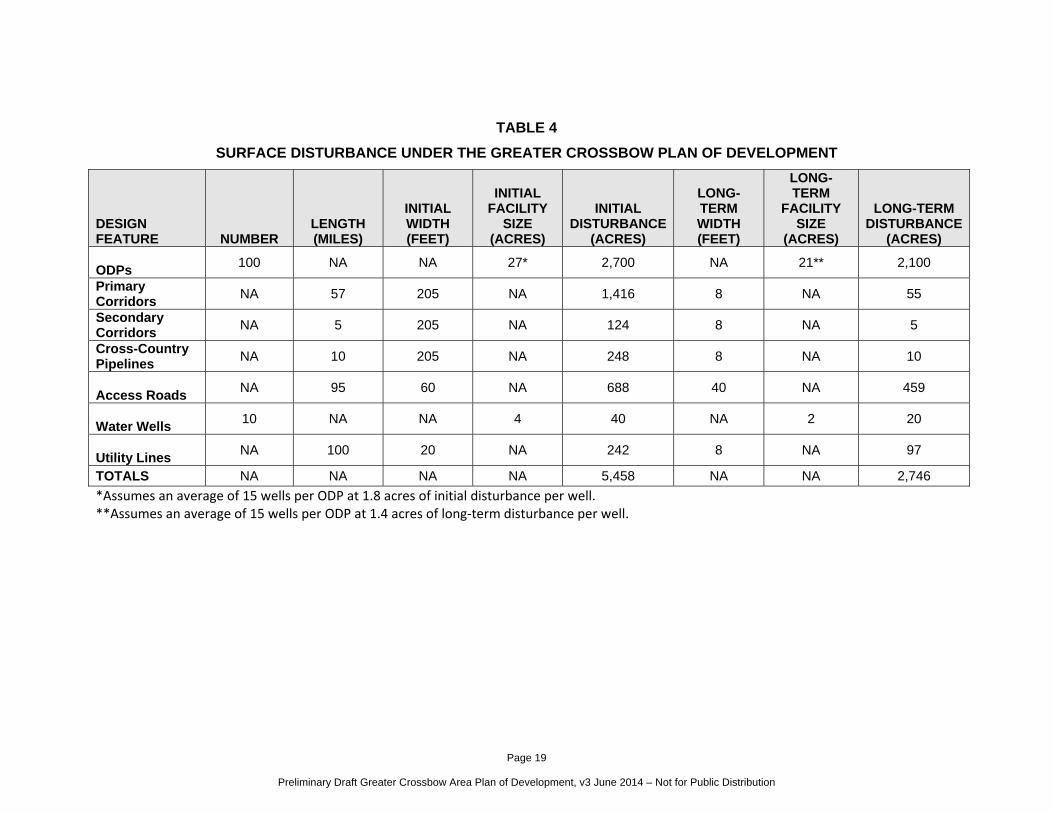
2.4.8 SURFACE DISTURBANCE ESTIMATES
Anticipated surface disturbance by design feature is summarized in Table 4.
As previously discussed, compared to traditional oil and gas field development, EOG’s ODP
proposal would result in a substantial reduction of surface disturbance on a per well basis. For
example, on average the long-term disturbance area for a traditional well pad in the PRB is
about 7 acres per well, which would equate to about 10,500 acres of long-term disturbance for
1,500 wells. Under the ODP strategy, each well would occupy a long-term disturbance area of
only about 1.4 acres, with a total of about 2,100 acres, which is approximately an 80 percent
reduction in per well disturbance compared to traditional development. Similarly, the placement
of ODP locations along strategically placed Primary Corridors would result in a substantial
reduction in overall surface disturbance compared to that of a traditional oil and gas field, where
pipelines and access roads are constructed in a “spider web” fashion across an entire Project
Area. The design of the Greater Crossbow Project would result in substantial areas of land that
would be left relatively undisturbed by new oil and gas activity, which would reduce overall
surface disturbance and habitat fragmentation.
Page 19
Preliminary Draft Greater Crossbow Area Plan of Development, v3 June 2014 – Not for Public Distribution
TABLE 4
SURFACE DISTURBANCE UNDER THE GREATER CROSSBOW PLAN OF DEVELOPMENT
DESIGN FEATURE NUMBER
LENGTH (MILES)
INITIAL WIDTH (FEET)
INITIAL FACILITY
SIZE (ACRES)
INITIAL DISTURBANCE
(ACRES)
LONG-TERM WIDTH (FEET)
LONG-TERM
FACILITY SIZE
(ACRES)
LONG-TERM DISTURBANCE
(ACRES) ODPs 100 NA NA 27* 2,700 NA 21** 2,100
Primary Corridors NA 57 205 NA 1,416 8 NA 55
Secondary Corridors NA 5 205 NA 124 8 NA 5
Cross-Country Pipelines NA 10 205 NA 248 8 NA 10
Access Roads NA 95 60 NA 688 40 NA 459
Water Wells 10 NA NA 4 40 NA 2 20
Utility Lines NA 100 20 NA 242 8 NA 97
TOTALS NA NA NA NA 5,458 NA NA 2,746
*Assumes an average of 15 wells per ODP at 1.8 acres of initial disturbance per well. **Assumes an average of 15 wells per ODP at 1.4 acres of long‐term disturbance per well.
Page 20
Greater Crossbow Area Plan of Development, September 2014 – Not for Public Distribution
2.5 DRILLING AND COMPLETION
The following sections describe EOG’s plan for drilling and completion in the Greater Crossbow
Project Area. To the greatest extent possible, EOG intends to conduct drilling and exploration
and development operations within the Project Area on a year-round basis to maximize the use
of horizontal development from multi-well pads. As part of this PoD, EOG is seeking approval
from the BLM to waive discretionary timing limitations on a programmatic basis (i.e., several
wells at a time for extended periods of time). Without this waiver, the application of timing
limitations would force EOG to move drilling rigs in and out of areas during portions of the year,
which would increase operational costs, decrease efficiencies, and potentially increase impacts
to wildlife and other sensitive resources.
2.5.1 DRILLING
Following construction, drilling rigs would be transported to the well site and erected on the
ODP. Current technology may allow each rig to drill 30 wells each year, depending on the
formation. Approximately eight drill rigs are anticipated to be operating in the Greater Crossbow
Project Area at the peak of the drilling phase. The actual number of rigs in the Project Area and
number of wells drilled during a given year would be dependent on the factors identified in
Section 2.2.
All equipment and vehicles associated with drilling activities would be confined to the approved
disturbance areas of the roads and ODPs. Wells would be drilled and completed in accordance
with WOGCC rules and regulations, BLM Onshore Oil and Gas Order No. 2, and other current
BLM guidelines. Detailed well construction plans would be included in the APD for any given
well.
Horizontal wells would be drilled vertically from each surface location to a predetermined point
above the target formation, referred to as the “kickoff point.” From here, the wellbore would
curve from its vertical trajectory to intersect the target reservoir at the “entry point,” then
continue horizontally through the reservoir until reaching the desired bottom-hole location.
Page 21
Greater Crossbow Area Plan of Development, September 2014 – Not for Public Distribution
Wells would be drilled to varying total measured depths (approximately 16,000 to 20,000 feet2)
to the Parkman, Turner, Mowry, Niobrara, Muddy, or possibly other formations. Drilling would
determine whether oil and gas production could be established. As soon as evaluation of the
production intervals is conclusive, any unproductive drill holes would be plugged and
abandoned in accordance with state and Onshore order requirements.
All proposed wells would be drilled using a closed-loop system, therefore no open reserve or
cuttings pits would be needed. The closed-loop system would consist of five above ground
tanks, varying in size from 30 to 80 cubic yards, for the containment of drill cuttings; and four
500-barrel (bbl) upright tanks for water-based mud storage. The storage area for these tanks
would be lined with a plastic liner and containment berms. There would be five 500 bbl upright
tanks for oil-based mud storage. The containment area for these tanks would also be lined with
a plastic liner and containment berms. The drill rig would also be set atop a plastic liner. All
liners would be 16 mil thickness.
Siphons, catchments, drip pans, and absorbent pads would be installed to keep hydrocarbons
produced by the drilling and/or completion rigs from contaminating surrounding soils.
Hydrocarbons and contaminated pads would be disposed of in accordance with Wyoming DEQ
requirements.
During drilling operations, a blowout preventer would be installed on the surface casing to
provide protection against uncontrolled entry of reservoir fluids into the wellbore in the event that
reservoir pressures exceed the hydrostatic pressure of the wellbore fluid. In addition, a flow
control manifold consisting of manual and hydraulically operated valves would be installed at
ground level. All pressure control devices would comply with the provisions of BLM's Onshore
Oil and Gas Order No. 2.
The casing and cementing program would be designed to protect wellbore integrity, isolate, and
protect the shallower formations encountered in the wellbore, and prohibit pressure
communication or fluid migration between zones. In addition, the cement would protect the well
2 Total Measured Depth range based on estimates provided by EOG for the Parkman, Turner, and Mowry Formations.
Page 22
Greater Crossbow Area Plan of Development, September 2014 – Not for Public Distribution
by preventing formation pressure from damaging the casing and retarding corrosion by
minimizing contact between the casing and formation fluids. EOG may also run downhole
evaluation logs prior or subsequent to setting and cementing production casing. Detailed site-
specific casing and cementing plans for each well would be included with each federal APD
package and approved by a BLM and/or State petroleum engineer.
Drilling operations for an individual well could require from 8 to 20 people, who would access an
ODP with 4 to 10 vehicles. The duration of drilling operations on a given well would vary
depending on the target formation, well depth, wellbore geometry, and/or conditions
encountered while drilling. However, in general an individual well could be drilled in 7 to 20
days depending on the target formation3.
Depending on the formation drilled, each well would require anywhere from 1,000 to 1,800 bbl4
of water to perform drilling operations. Water for drilling would be obtained from the sources
identified in Section 2.6.
2.5.2 COMPLETIONS
Completion operations would commence after a well is drilled and the potential well productivity
has been determined. Completion operations consist of perforating the production casing,
stimulating the formation(s) using hydraulic fracturing techniques, flowing back the fracturing
fluids to the surface, flow testing to determine post-fracture productivity, and installation of
production equipment.
After production casing is perforated, stimulation would consist of hydraulically fracturing the
producing formation. A water/sand slurry would be used with gels and other additives to ensure
the quality of the fracture fluid. Slurry would be pumped down the well bore through
perforations in the casing and into the formation. Pumping pressures and slurry flow rates
would be increased to the point at which fractures propagate outward from the perforations into
the formation and the slurry flows rapidly into the fractures. The sand serves as a proppant to
3 Drilling timeframe based on estimates provided by EOG for the Parkman, Turner, and Mowry Formations. 4 Water volumes for drilling based on estimates provided by EOG for the Parkman, Turner, and Mowry Formations.
Page 23
Greater Crossbow Area Plan of Development, September 2014 – Not for Public Distribution
keep the created fracture open after the pressure drops, thereby allowing reservoir fluids to
move more readily into the well.
Hydraulic fracturing is a well understood and commonly employed technology used on
potentially productive reservoirs at depths below usable aquifers. Hydraulic fracturing
processes and required disclosures would be conducted in accordance with all current and
future WOGCC, BLM, and any other applicable rules. The WOGCC requires operators to
disclose the types and amounts of hydraulic fracturing chemicals used prior to stimulation
(WOGCC 2010). EOG would also disclose the contents of hydraulic fracturing fluid used in the
proposed wells to the public through FracFocus, a website managed jointly by the Ground
Water Protection Council and the Interstate Oil and Gas Compact Commission
(http://fracfocus.org). The website allows the public access to general information, water
volumes, and chemical information for registered wells in a format consistent with material
safety data sheets, including the Chemical Abstract Service number and the ingredient
percentage in both the additive and hydraulic fracturing fluids. This registry provides a means
for oil and gas operators to voluntarily provide key information to the public in a timely fashion.
In addition, EOG would comply with U.S. Environmental Protection Agency (EPA) requirements
40 CFR Part 60, Subpart OOOO that requires notification 2 days prior to completion of any gas
well that will include hydraulic fracturing.
EOG would utilize "green completions" on new wells to limit the venting or flaring of natural gas.
According to Wyoming Air Quality Standards and Regulations (WAQSR) Chapter 6, Section 2,
Oil and Gas Production Facilities Permitting Guidance (September 2013), wells located in
Converse and Campbell counties are not required to utilize “green completions.” However, all
gas well completions with hydraulic fracturing must follow specific “green completion” guidelines
according to 40 CFR Part 60, Subpart OOOO. Under Subpart OOOO these wells must recover
liquids during flowback and route to storage tanks or re-inject them. All recovered gas shall be
re-routed, used, or put into a collection system with no direct release to the atmosphere. Only if
recovered flowback gas cannot be put to a gas flow line, may it be captured and flared.
Economically viable wells would be connected to permanent production facilities and wells
would be turned to production through those facilities. Post stimulation flow tests would allow
for recovery of stimulation fluids and evaluation of well productivity. Recovered fluids would
Page 24
Greater Crossbow Area Plan of Development, September 2014 – Not for Public Distribution
include variable amounts of produced water in addition to stimulation fluids. Flow testing
duration would vary depending on individual well performance but typically would be conducted
only long enough for fluid rates to drop to a level that permanent production equipment can
safely process. Portable and/or permanent production equipment would be utilized to separate
fluids from the flow back stream, allowing recovered fluids to be directed to storage tanks.
Fluids recovered during flow back operations would be transported from the storage tanks to an
approved disposal facility. Oil would be contained in tanks and ultimately sold.
Wells drilled to the Turner or Mowry formations would not be flared. Instead, they would be shut
in until connected to pipeline. Wells drilled to the Parkman Formation would typically be flared
for up to 14 days after initial production, and then EOG would either secure a permit to continue
flaring or shut in the well until connected to pipeline. If there is an emergency upset in the
gathering system EOG is authorized to flare gas under WOGCC Chapter 3 Section 39. If a
shutdown is longer than 24 hours EOG is required to secure a permit to flare over the shutdown
period or to the maximum volume that the state allows. In addition, in accordance with the U.S.
Department of the Interior NTL-4A memo, “Royalty or Compensation for Oil and Gas Loss” EOG
is authorized to flare gas without incurring a royalty obligation in an emergency situation. Under
Part III of the memo, Authorized Venting and Flaring of Gas, a temporary emergency situation is
authorized for up to 24 hours per incident, and up to 144 hours during any calendar month. All
other applicable requirements within the NTL-4A memo or future regulations would be followed
as well.
Completion operations for an individual well could require from 4 to 30 people who would
access the ODP with 2 to 20 vehicles. Depending on the formation, an individual well could be
stimulated and completed in 17 to 22 days5.
Depending on the formation and the number of stimulations required, anywhere from 60,000 to
150,000 bbl of water6 would be required to complete an individual well. Water for completions
would be provided by 10 proposed water source wells. In addition, as feasible, EOG would use
5 Completion timeframe based on estimates provided by EOG for the Parkman, Turner, and Mowry formations. 6 Water volumes for completion based on estimates provided by EOG for the Parkman, Turner, and Mowry formations.
Page 25
Greater Crossbow Area Plan of Development, September 2014 – Not for Public Distribution
a limited volume of treated or recycled water during completion operations. See Section 2.6.2
for additional information on proposed water use.
If a well is determined to be non-productive, the well would be completed as a dry hole. In
accordance with 43 CFR 3160, a Well Completion Report and Log (Form 3160-4) would be
submitted within 30 days after completion of each well or after completion of well operations
being performed.
2.6 WATER REQUIREMENTS AND WATER SOURCES
2.6.1 WATER REQUIREMENTS
Water requirements for construction, drilling, completion, and dust abatement are summarized
in Table 5.
TABLE 5
WATER REQUIREMENTS FOR THE GREATER CROSSBOW PROJECT
PROJECT PHASE/TASK
WATER VOLUME (TOTAL BBL)
Dust Abatement During Construction Per ODP 1,200 Per One Mile of Access Road/Pipeline Corridor 1,500
Drilling (Per Well) Parkman 1,000
Turner 1,500
Mowry 1,800
Completion (Per Well) Parkman 60,000
Turner 60,000
Mowry 150,000
Dust Abatement During Production Per One Mile of Access Road 1,500
Page 26
Greater Crossbow Area Plan of Development, September 2014 – Not for Public Distribution
2.6.2 WATER SOURCES
Water for drilling, completion, and dust abatement would be obtained from approved, permitted,
and new sources. Existing water sources would include four existing water wells located within
the Greater Crossbow Project Area, as well as permitted water sources outside the Project
Area. EOG is also proposing to drill ten new water source wells to aquifers that would be drilled
on or near the Primary Corridor system. Specific locations of proposed water source wells are
anticipated to be located on private lands. All water source wells would be properly permitted
and approved through the Wyoming State Engineers Office, and in coordination with the private
surface owner.
Water for drilling and completion would initially be trucked to the ODPs. However, as the
Primary Corridor system is developed, water would also be piped to the ODPs, thereby reducing
water truck traffic. The specific water sources for an individual well would be identified at the
time of APD submittal.
2.7 PRODUCTION FACILITIES AND OPERATIONS
Each ODP would include the wellheads and potential pumpjacks, and then separate production
equipment located and operated on a portion of the ODP separate from the wellheads. The
primary purpose of the production equipment is for oil treating, heating and separation, gas
dehydration, and temporary storage of liquids, vapor stabilization, and vapor recovery. During
normal operations, the liquids from these tanks would be piped offsite as soon as practical.
Power required for the production equipment would initially be provided via gas-driven engines,
but as technically and economically feasible would eventually be converted to electric engines
(Section 2.7.4).
Production equipment per a 22-well ODP could include up to the following equipment (if
authorization for comingling is provided, the number of tanks required would be reduced
substantially):
Page 27
Greater Crossbow Area Plan of Development, September 2014 – Not for Public Distribution
50 oil storage tanks between 400 and 750 bbl (29,800 bbl of total storage) (an average
of approximately 2.3 oil storage tanks per well)
26 water storage tanks between 400 and 750 bbl (16,000 bbl of total storage) (an
average of approximately 0.5 water storage tanks per well)
8 emergency storage tanks between 400 and 500 bbl (3,800 bbl of total storage) (an
average of less than 0.2 emergency storage tanks per well)
8 bad oil storage tanks between 400 and 500 bbl (3,800 bbl of total storage) (an average
of less than 0.2 bad oil storage tanks per well)
6 triethylene glycol (TEG) dehydration units
8 glycol heaters
22 pumping units
16 high pressure separators
8 fuel gas scrubbers
14 sales gas scrubbers
30 horizontal or vertical heater treaters
16 indirect heaters
8 vapor recovery towers (VRTs)
8 vapor recover units (VRUs)
6 enclosed flares
2 elevated flares
The gas produced from the wellheads and heater treater outlet would be sent through the
dehydration units and the sales gas scrubbers before being piped offsite.
The VRTs would recover vapor from the tanks, and use a stabilization process to lower the
pressure, lowering the volatility of the product, and thus lowering the potential for emissions.
The gas would then be sent to the VRUs. In some instances the vapor would be re-used on-site
when practicable, which would include use of the fuel scrubbers, and in other instances the gas
would be sent to a flare for destruction (control) of air emissions.
Actual operations of the production equipment would be dependent on the success of the
exploratory wells. The quantity of equipment and configuration could change to accommodate
lower or higher quantities of gas or liquids recovered from exploratory wells.
Page 28
Greater Crossbow Area Plan of Development, September 2014 – Not for Public Distribution
2.7.1 COMPRESSION
EOG anticipates an estimated 1,000 horsepower (HP) of new compression within the Project
Area. It is estimated that the added compression would require a single new central
compression facility. The facility would be constructed similar to an ODP, as described in
Section 2.4.1. There would be no additional gas processing facilities constructed and/or
operated by EOG under the scope of the Project.
2.7.2 GROUNDWATER SAMPLING
EOG has developed a Groundwater Baseline Sampling Program to establish baseline
groundwater conditions in the vicinity of new oil and gas well locations before drilling begins.
This program meets the requirements and protocols established in Chapter 3, Section 46 of the
WOGCC Rules and Regulations for the groundwater baseline sampling, analysis, and
monitoring program.
Water samples would be collected from up to four water wells located within 0.5 mile of the
surface location in a radial pattern from a proposed oil or gas well. These baseline samples
would be collected prior to the setting of the well conductor casing. Sampling would only be
conducted if landowner access is granted.
Post-completion sampling and analysis would be performed between 12 and 24 months and
between 36 and 48 months after setting the production casing or liner. Post-completion samples
may also be collected from wells from which baseline samples were collected in response to
landowner complaints of a distinct or measurable change in water quality (i.e., change in odor,
color, taste, or turbidity). Every effort would be made to perform post-completion sampling
during the same month that baseline sampling is performed.
2.7.3 PRODUCED WATER MANAGEMENT AND DISPOSAL
Produced wastewater would be confined to a storage tank for a period not to exceed 90 days
after initial production of an individual well. During the early stages of the Greater Crossbow
Project, produced water would be trucked for disposal to one of the following locations: McBeth
Water Disposal, North Douglas Water Disposal, Lynch Water Disposal, or the North Bill
Disposal. However, EOG intends to eventually convert four of their producing wells to salt water
Page 29
Greater Crossbow Area Plan of Development, September 2014 – Not for Public Distribution
disposal (SWD) wells, to which produced water would be piped via the Primary Corridor system.
Locations for SWD wells would be determined based on reservoir injection quality. All SWD
wells would be properly permitted and approved through the WOGCC.
2.7.4 WORKOVERS AND RECOMPLETIONS
Periodically, EOG may perform a workover on a well to keep the well operating efficiently.
Workovers may be necessary to repair the wellbore equipment (casing, tubing, etc.) and/or the
wellhead, or to improve well performance. EOG may also recomplete a well to produce oil or
natural gas from a different interval in a wellbore. Both workover and recompletion operations
generally occur during daylight hours. A typical workover or recompletion operation would
require approximately 3 days; however, they can range from 1 to 10 days, or more, depending
on the complexity of the work required. Manpower requirements for these operations average 6
people, ranging from 4 to 30 people at a particular time. The frequency for this type of work
cannot be accurately projected since workovers and/or recompletions vary by well and depend
on well-specific circumstances. Both workovers and recompletions would be performed in
accordance with appropriate requirements. Neither operation would result in additional surface
disturbance.
2.7.5 HAZARDOUS MATERIALS AND SOLID WASTE
A variety of chemicals, including lubricants, paints, and additives, would be used during drilling
and completion operations. Some constituents of these materials contain hazardous
substances. Hazardous materials can include some greases or lubricants, solvents, acids, paint,
and herbicides, among others. These materials would not be stored at well locations although
they may be kept in limited quantities on drilling sites and at production facilities for short
periods of time. None of the chemicals that would be used during drilling, completion, or
production operations meet the criteria for being an acutely hazardous material/substance or
meet the quantities criteria per BLM Instruction Memorandum No. 93-344. Chemicals subject to
reporting under Title III of the Superfund Amendments and Reauthorization Act in quantities of
10,000 pounds or more would not be used, produced, stored, transported, or disposed of
annually while drilling or completing a well in the Greater Crossbow Project Area. In addition,
extremely hazardous substances, as defined in 40 CFR 355, in threshold planning quantities,
Page 30
Greater Crossbow Area Plan of Development, September 2014 – Not for Public Distribution
would not be used, produced, stored, transported, or disposed of while drilling or completing a
well.
Most wastes that would be generated by the Project are excluded from regulation by the
Resource Conservation and Recovery Act (RCRA) under the exploration and production
exemption in Subtitle C (40 CFR 261.4(b)(5)) and are considered to be solid wastes. These
wastes include those generated at the wellhead and through the production stream or gas
plants. Exempt wastes include produced water, production fluids (i.e., drilling mud or well
stimulation flow-back fluids), and soils affected by spills of these fluids.
Any unintentional release of oil, gas, salt water, or other such fluids would be immediately
addressed by onsite remediation and /or removal to an approved disposal site. The spill would
be reported to the Authorized Officer (AO) of the appropriate SMA and other appropriate
authorities. EOG would develop and maintain a Spill Prevention, Control, and
Countermeasures (SPCC) Plan for each well in the Project Area. To satisfy SPCC Plan
requirements, storage facilities and tanks would use secondary containment structures of
sufficient capacity to contain, at a minimum, the entire contents of the largest tank, with
sufficient freeboard to contain precipitation after the well goes into production. Any spills or
releases of regulated wastes or materials would be investigated, responded to, and remediated
in accordance with BLM, USFS, WOGCC, EPA, and WDEQ regulations and guidance.
Drill cuttings would be stored on the ODP in a containment tank at each well location. Fracture
stimulation fluids would be flowed back into above-ground tanks and hauled to a WDEQ-
authorized disposal site.
Portable chemical toilets would be provided for the use of workers during well drilling and
completion operations. Toilets would be pumped as required and the waste disposed of by a
commercial operator.
All garbage and non-flammable waste materials would be stored in self-contained portable
dumpsters or trash cages. Trash and debris would be picked up daily and deposited in an
appropriate container. As needed and upon completion of operations, accumulated trash would
be cleaned up and removed from the location and transported to a state-approved waste
Page 31
Greater Crossbow Area Plan of Development, September 2014 – Not for Public Distribution
disposal site. Immediately upon removal of the drilling equipment, the container would be
removed from the site until such time as the next well is to be drilled on the ODP.
2.7.6 RECLAMATION AND ABANDONMENT
EOG would develop a reclamation plan and perform reclamation activities in conformance with
the preferences of the appropriate SMA or private surface owner. In addition, EOG would
comply with the Wyoming Reclamation Policy as currently expressed in BLM Wyoming
Instruction Memorandum 2012-032 (4/2/12). EOG’s reclamation strategy would remain
adaptive to address results from ongoing monitoring and would implement advances in
reclamation. EOG’s reclamation goals would include:
Developing procedures and strategies to ensure successful interim and final reclamation
operations in the Greater Crossbow Project Area;
Modifying procedures and strategies as needed throughout the life of the Project;
Developing procedures for reclamation monitoring and reporting; and
Evaluating reclamation performance on an ongoing basis in terms of successful site
stabilization.
Interim Reclamation
EOG would perform interim reclamation on all disturbed areas of an ODP, pipeline corridor, or
access road not needed for ongoing drilling operations or long-term production operations. As
previously discussed, each ODP (assuming average development of 15 wells per ODP) would
be reduced to approximately 21 acres following interim reclamation. Interim reclamation of the
ODPs would occur only after all wells on a given pad have been drilled. Interim reclamation of
the pipeline corridors would occur soon after all pipelines have been installed. Each pipeline
corridor would be reclaimed back to an approximately 8-foot wide swath, which would be
needed to accommodate a two-track road for pipeline maintenance. Utility line corridors would
also be reclaimed to an approximately 8-foot swath to accommodate a two-track road for
maintenance. As the utility lines would be plowed in, interim reclamation would start
immediately following utility line installation (i.e., concurrent with installation).
Page 32
Greater Crossbow Area Plan of Development, September 2014 – Not for Public Distribution
To minimize repeated disturbance EOG would implement in-place topsoil banking. This
banking process involves reducing the number of times the topsoil is stripped and re-spread.
Topsoil would be stripped during initial ODP construction and would remain stockpiled during
drilling and completion operations. Upon completion of drilling operations or completion of a
pipeline corridor or access road, all salvaged topsoil would be re-spread over areas not needed
for production operations. The topsoil would be spread and graded with a relatively smooth
surface devoid of larger aggregate and then reseeded with a seed mixture prescribed by the
SMA or surface owner. Cut and fill slopes would be stabilized and BMPs would be implemented
to reduce potential erosion. Ongoing monitoring of the reclaimed area would indicate if
reseeding or other reclamation activity will be needed to promote vegetation regrowth and soil
stabilization.
Final Reclamation
At final abandonment of an individual well, the casing would be cut off at the base of the cellar
or 3 feet below the final restored ground level, whichever is deeper. EOG would follow the final
abandonment procedures prescribed by the BLM and/or State.
Surface equipment (including surface pipeline) would be removed from the ODP and pipeline
corridor when no longer needed by any of the remaining producing wells. Buried flowlines in the
associated Secondary Corridor would undergo final pigging for removal of fluids, be opened to
the air, and then abandoned in place to avoid unnecessary surface disturbance. Final
reclamation of an ODP would be performed after all wells on an ODP well pad cease
production. Similarly, final reclamation of a Primary Corridor would occur after all wells
connecting to that Primary Corridor cease production. After salvage of all topsoil from the
interim reclaimed portions of the ODP, access road, or pipeline corridor, the locations would be
re-contoured to preexisting profile, topsoil would be redistributed, and the surface would be
planted with a seed mixture specified by the SMA or surface owner. An abandoned ODP, its
road, and associated pipeline corridors would be restored as near as practical to its original
condition.
Page 33
Greater Crossbow Area Plan of Development, September 2014 – Not for Public Distribution