30
―1― GReddy Turbo Kit HONDA S2000 AP1 (2000-2003 F20C) T518Z 8cm 2

―1―
GReddy Turbo Kit
HONDA S2000 AP1 (2000-2003 F20C) T518Z 8cm2
―2―
HONDA S2000 AP1 (F20C) T518Z 8cm2
Installation Manual Please read the entire manual before installing this kit. Application: Make Model Chassis Year HONDA S2000 AP1 00~~~~03
• This GReddy Turbo Kit Is designed only for the vehicles specified above.
• Premium grade gasoline (91 octane or higher) is required with this Kit.
• Make sure that the vehicle is not equipped with any ECM upgrade chips.
• Use of GReddy Racing Spark Plugs ISO #8 or NGK plugs (colder than factory) is recommended with this kit.
※ The following parts are necessary for proper installation of the kit.
Honda Genuine Parts:
・Part Name Gasket, Exhaust manifold P/# 18115-PCX-004 Quantity 1
・Part Name Gasket, Silencer P/# 16705-PD1-003 Quantity 1
・Part Name Sealing Washer P/# 90428-PD6-003 Quantity 1
Important • This installation should only be performed by a trained specialist who is very familiar
with the automobile’s mechanical, electrical and fuel management system. • If installed by an untrained person, it may cause damage to the kit as well as the
vehicle. • GReddy Performance Products Inc. is not responsible for any damage to the vehicle’s
electrical system caused by improper installation. • This kit is for off-road use vehicle only which may never be driven on a public highway
―3―
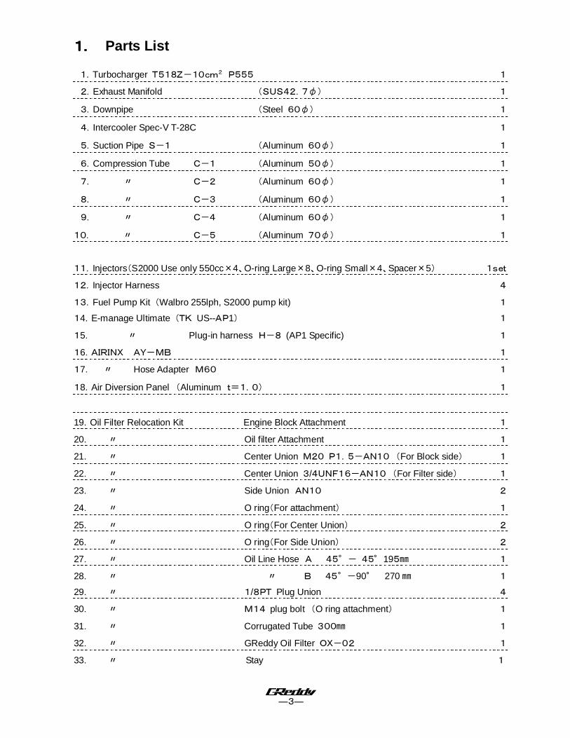
1111.... Parts List
1.Turbocharger T518Z-10cm
2
P555 1
2.Exhaust Manifold (SUS42.7φ) 1
3.Downpipe (Steel 60φ) 1
4.Intercooler Spec-V T-28C 1
5.Suction Pipe S-1 (Aluminum 60φ) 1
6.Compression Tube C-1 (Aluminum 50φ) 1
7. 〃 C-2 (Aluminum 60φ) 1
8. 〃 C-3 (Aluminum 60φ) 1
9. 〃 C-4 (Aluminum 60φ) 1
10. 〃 C-5 (Aluminum 70φ) 1
11.Injectors(S2000 Use only 550cc×4、O-ring Large×8、O-ring Small×4、Spacer×5) 1set
12.Injector Harness 4
13.Fuel Pump Kit (Walbro 255lph, S2000 pump kit) 1
14.E-manage Ultimate (TK US--AP1) 1
15. 〃 Plug-in harness H-8 (AP1 Specific) 1
16.AIRINX AY-MB 1
17. 〃 Hose Adapter M60 1
18.Air Diversion Panel (Aluminum t=1.0) 1
19.Oil Filter Relocation Kit Engine Block Attachment 1
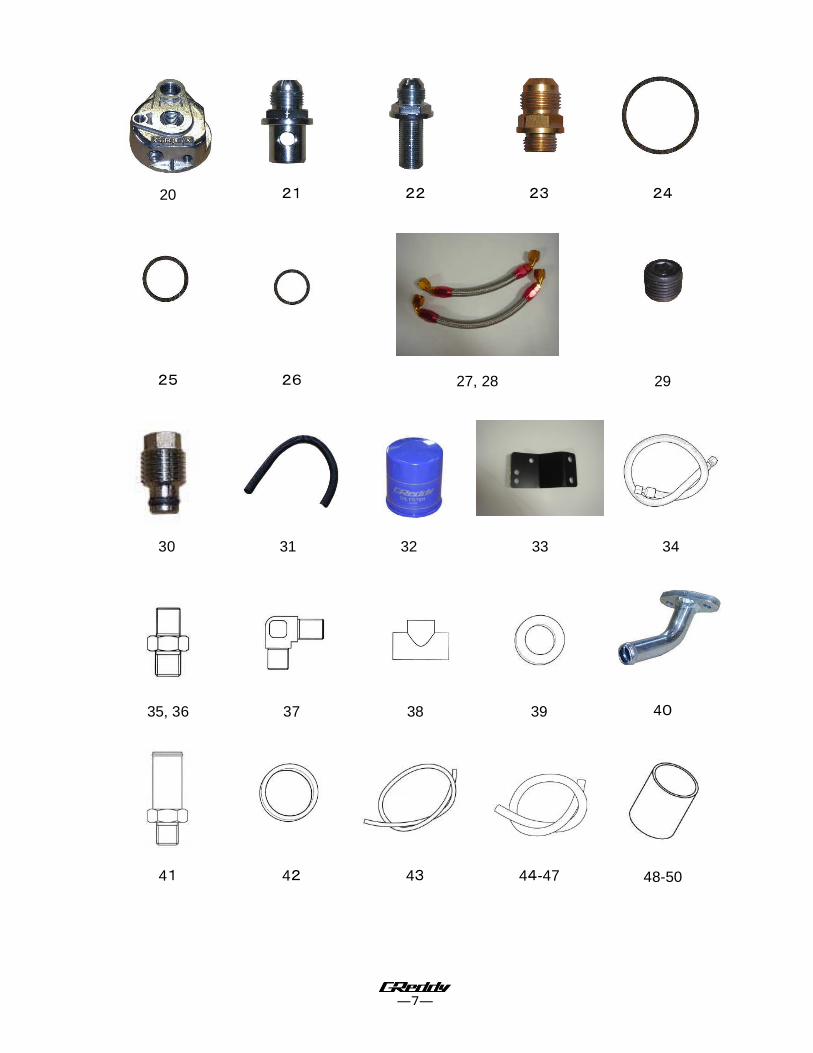
20. 〃 Oil filter Attachment 1
21. 〃 Center Union M20 P1.5-AN10 (For Block side) 1
22. 〃 Center Union 3/4UNF16-AN10 (For Filter side) 1
23. 〃 Side Union AN10 2
24. 〃 O ring(For attachment) 1
25. 〃 O ring(For Center Union) 2
26. 〃 O ring(For Side Union) 2
27. 〃 Oil Line Hose A 45°- 45°195㎜ 1
28. 〃 〃 B 45°-90° 270 ㎜ 1
29. 〃 1/8PT Plug Union 4
30. 〃 M14 plug bolt (O ring attachment) 1
31. 〃 Corrugated Tube 300㎜ 1
32. 〃 GReddy Oil Filter OX-02 1
33. 〃 Stay 1
―4―
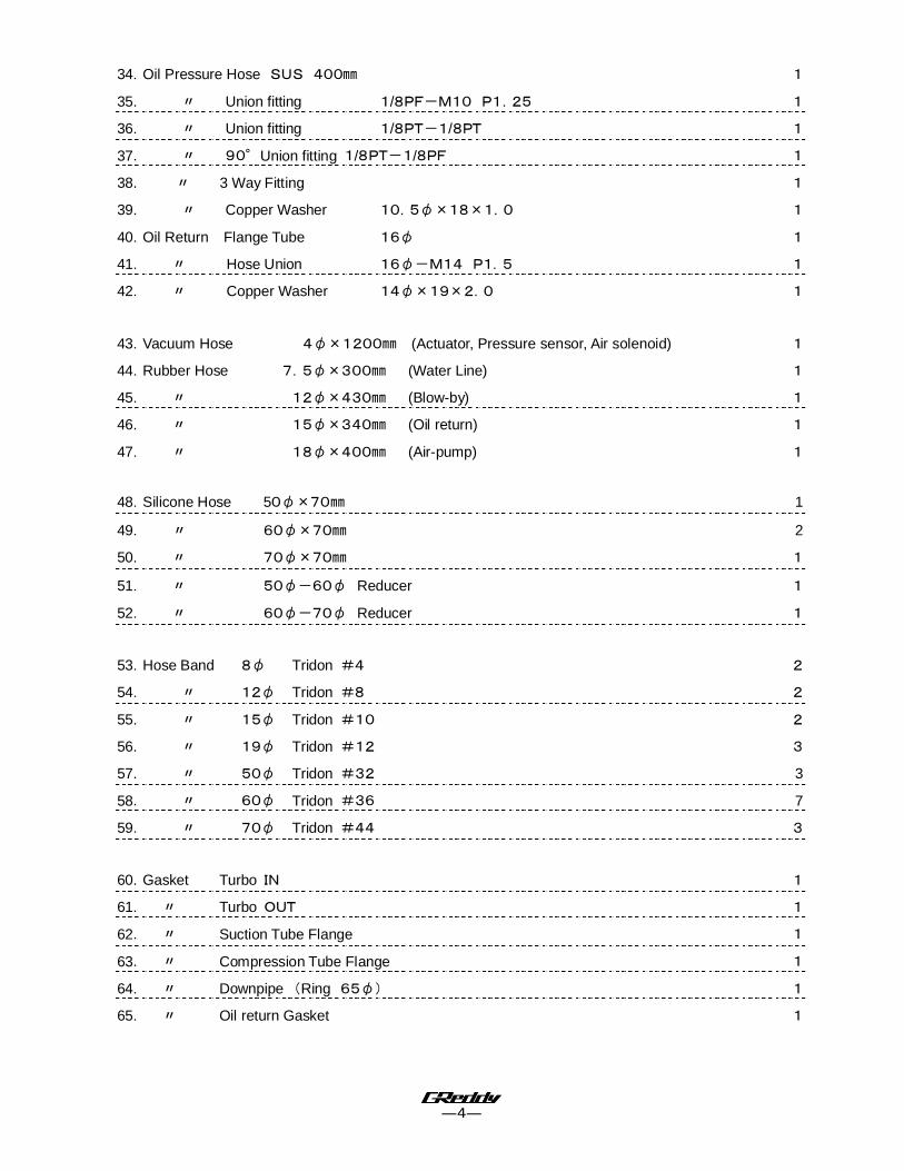
34.Oil Pressure Hose SUS 400㎜ 1
35. 〃 Union fitting 1/8PF-M10 P1.25 1
36. 〃 Union fitting 1/8PT-1/8PT 1
37. 〃 90°Union fitting 1/8PT-1/8PF 1
38. 〃 3 Way Fitting 1
39. 〃 Copper Washer 10.5φ×18×1.0 1
40.Oil Return Flange Tube 16φ 1
41. 〃 Hose Union 16φ-M14 P1.5 1
42. 〃 Copper Washer 14φ×19×2.0 1
43.Vacuum Hose 4φ×1200㎜ (Actuator, Pressure sensor, Air solenoid) 1
44.Rubber Hose 7.5φ×300㎜ (Water Line) 1
45. 〃 12φ×430㎜ (Blow-by) 1
46. 〃 15φ×340㎜ (Oil return) 1
47. 〃 18φ×400㎜ (Air-pump) 1
48.Silicone Hose 50φ×70㎜ 1
49. 〃 60φ×70㎜ 2
50. 〃 70φ×70㎜ 1
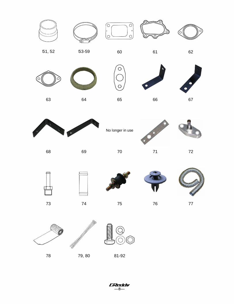
51. 〃 50φ-60φ Reducer 1
52. 〃 60φ-70φ Reducer 1
53.Hose Band 8φ Tridon #4 2
54. 〃 12φ Tridon #8 2
55. 〃 15φ Tridon #10 2
56. 〃 19φ Tridon #12 3
57. 〃 50φ Tridon #32 3
58. 〃 60φ Tridon #36 7
59. 〃 70φ Tridon #44 3
60.Gasket Turbo IN 1
61. 〃 Turbo OUT 1
62. 〃 Suction Tube Flange 1
63. 〃 Compression Tube Flange 1
64. 〃 Downpipe (Ring 65φ) 1
65. 〃 Oil return Gasket 1

―5―
66.Bracket Intercooler 1
67. 〃 Air pump 1
68. 〃 Vacuum Tank 1
69. 〃 Air Diversion Panel 1
70. *No longer used in this kit*
71. 〃 Pressure Sensor 1
72.Pressure Sensor Adapter 1
73.Hose Union 5φ-1/8PT 1
74.19φHose Union 1
75.Rubber Mount 2
76.Clip 3
77.Air Duct 50φ×1000㎜ 1
78.Thermo Cloth 100×1000㎜ 2
79.Zip Tie 100㎜(Black) 10
80.Zip Tie 200㎜(Black) 10
81.M4×18㎜ P0.7 + Head B - - N (Pressure Sensor) 2
82.M5×12㎜ P0.8 + Head B - - N (Sec. Air Solenoid Valve) 1
83.M6×15㎜ P1.0 Stainless B S/W - - (Oil filter re-locater stay) 2
84.M6×15㎜ P1.0 Stainless B S/W F/W - (Oil Return, Baffle plate stay) 3
85.*No longer used in this kit*
86.M6×25㎜ P1.0 Stainless B S/W F/W - (Pressure Sensor Stay) 2
87.M6Flange Nut P1.0 Steel (Rubber Mount) 2
88.M8×15㎜ P1.25 Stainless B S/W - - (Oil filter re-locater stay) 2
89.M8×15㎜ P1.25 Stainless B S/W F/W N (Air pump, I/C, I/C stay, C-4) 6
90.M8×20 ㎜ P1.25 Stainless B S/W F/W - (Turbine Compressor IN/OUT 4
91.M8×30 ㎜ P1.25 Stainless Stud B S/W - N (Turbine Exhaust IN/OUT) 9
92.M10×20㎜ P1.25 Stainless B S/W F/W N (Downpipe Stay) 1
―6―
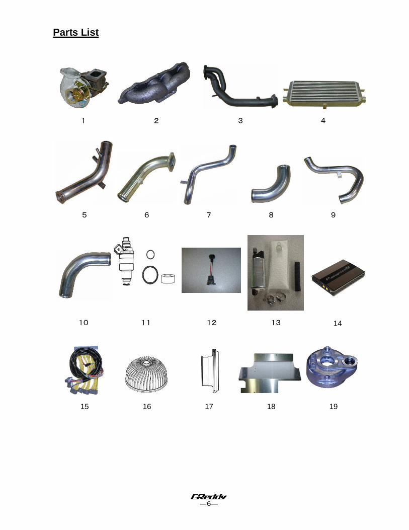
Parts List
1 2 3 4
5 6 7 8 9
10 11 12 13 14
15 16 17 18 19
―7―
20 21 22 23 24
25 26 27, 28 29
30 31 32 33 34
35, 36 37 38 39 40
41 42 43 44-47 48-50
―8―
51, 52 53-59 60 61 62
63 64 65 66 67
No longer in use
68 69 70 71 72
73 74 75 76 77
78 79, 80 81-92
―9―
2. Removal of Stock Parts When removing the stock parts, make sure you read over the factory
repair manual for the proper procedures.
2-1 Disconnect the battery. Write down the radio presets and be sure to have the code for the factory radio.
2-2 Relieve the fuel pressure in the fuel system. (see factory repair manual for detail
procedure). 2-3 Drain the engine oil. 2-4 Remove the Air cleaner assembly with intake tube, and breather hose. 2-5 Remove the exhaust manifold and heat sheilds. 2-6 Remove the two engine under covers and the front bumper.

―10―
3. Kit Installation
3-1 Turbo Installation
(1) Before installing the turbo charger, make sure to
insulate the surrounding components with the
provided thermo cloth. Since the area around
the exhaust manifold will get very hot, it is
important to insulate the surrounding components
to prevent fire/heat damage.
(2) Install the #91 studs on the exhaust housing.
Install the #35 union with #39 brass washer on the
top side of the turbo as shown.
〈Parts used: 35, 39, 91〉
(3) Install the #91 studs onto the exhaust manifold,
then attach the turbo to the manifold. Be sure to
use the provided gasket between the turbo and
manifold #60.
〈Parts used: 1, 2,60,91〉
(4) Unclip the plug going to the Vtec Solenoid as
shown by the arrow in the image. Temporarily
remove the OEM intake support bracket that is
attached to the passenger side of the chassis.
Pass the turbocharger assembly through this
space from the front of the engine towards its
destination. Be cautious not to damage the
turbocharger or any engine parts during this
process, as it is a close fit.
(5) Use the new OEM exhaust manifold gasket when
installing the turbocharger assembly onto the
motor.
(6) Tighten the exhaust turbocharger assembly onto
the cylinder head using the OEM nuts.
(7) Install #40 oil return tube with #65 gasket on the
bottom side of the turbo with the provided #84
bolts as shown in section 3- 3.
〈Parts used: 40,65,84〉
№35
Do not install oil
return yet
№91

―11―
3-2 Oil Pressure Switch
(1) Remove the factory oil pressure switch. Install #36
union into the #38 three way fitting. Proceed to
install into the block where the oil pressure switch
was located.
*Be sure to use Teflon tape on each side of the
union.
〈Parts used: 36,38〉
(2) Install the factory oil pressure switch to the part of
the three way fitting facing the front of the car.
※ Install the 90° fitting #37 facing upwards as
shown.
※ Be sure to use Teflon tape on the 90°fitting (3
way fitting side ONLY) and on the oil pressure
switch.
〈Parts used: 37〉
3-3 Oil Filter relocation
(1) Install Unions #21 & #23 into Oil Block adapter
#19. Make sure to use the provided O rings #25 &
#26 on the unions and #24 on the adapter. Install
union plugs #29 into the adapter as shown.
※ Lubricate the o-ring and the thread to prevent any
cross threading and damaging the o-ring.
※ Apply Teflon tape on the 1/8PT plugs and make
sure not to over torque.
〈Parts used: 19, 21, 23, 24, 25, 26, 29〉
(2) Install the adapter as shown. The #23 union
should be facing in the 7 o’clock position, tighten
the #21 union so the adapter is secured in this
position.
※ Lubricate the O-ring and the thread to prevent any
cross threading and damaging the o-ring.
№38
№36
№37
Oil press sensor
№29
№21,25 №23,26
№24

―12―
(3) Install #29 union plugs in the 2 locations in
adapter #20 as shown. Install union #22 with O
ring #25 and union #23 with O ring #26 in the
adapter as shown. Install plug bolt #30 as shown.
※ Lubricate the o-ring and the thread to prevent any
cross threading and damaging the o-ring.
※ Apply Teflon tape on the 1/8PT plugs and make
sure not to over torque.
〈Parts used: 20,22,23,25,26,29,30〉
(4) Attach bracket #33 to the adapter using bolts #88.
Attach the oil filter to the adapter, be sure to use a
little oil on the filter seal.
※ Lubricate the O-ring on the filter.
〈Parts used: 32,33,88〉
(5)(5)(5)(5) Attach the filter adapter to the passenger side
shock tower using the provided M6 bolts #83.
〈Parts used: 83〉
№23,26
№22,25
№30
№29
№29
―13―
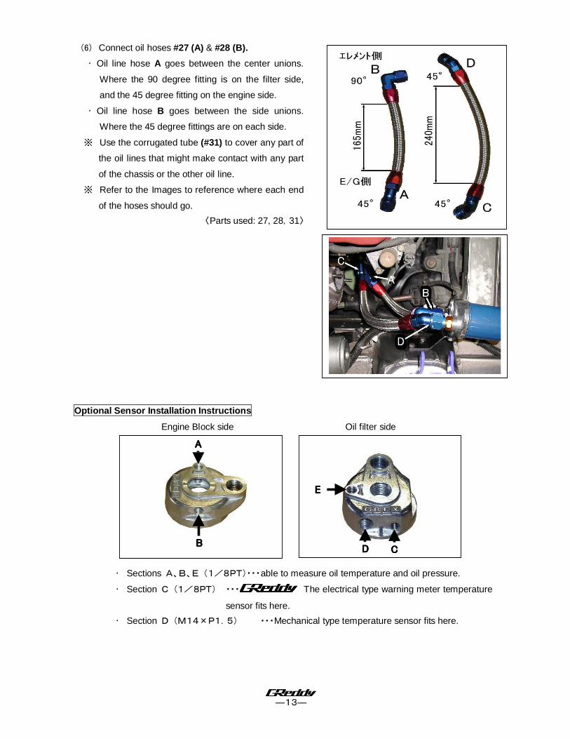
(6) Connect oil hoses #27 (A) & #28 (B).
・ Oil line hose A goes between the center unions.
Where the 90 degree fitting is on the filter side,
and the 45 degree fitting on the engine side.
・ Oil line hose B goes between the side unions.
Where the 45 degree fittings are on each side.
※ Use the corrugated tube (#31) to cover any part of
the oil lines that might make contact with any part
of the chassis or the other oil line.
※ Refer to the Images to reference where each end
of the hoses should go.
〈Parts used: 27, 28,31〉
Optional Sensor Installation Instructions
Engine Block side Oil filter side
・ Sections A、B、E (1/8PT)・・・able to measure oil temperature and oil pressure.
・ Section C (1/8PT) ・・・ The electrical type warning meter temperature
sensor fits here.
・ Section D (M14×P1.5) ・・・Mechanical type temperature sensor fits here.
AAAA
BBBB
EEEE
DDDD CCCC

―14―
3-4 Oil Feed Line installation
(1) Install the #34 oil feed line as shown, connecting
one end to the 90°fitting from the oil pressure
switch and the other to the union on the top side
of the turbo. Bend the line to make room for the
compression pipe on the turbo. Be careful not to
kink the line. Be sure that the oil line does not
make contact with any other parts.
〈Parts used: #34〉
(2) Remove the factory oil drain bolt and crush
washer. Using #41 Union and #42 brass washer,
install where the factory oil drain bolt was located.
〈Parts used: 41, 42〉
(3) Cover the #46 15φhose with thermo cloth (#78)
and connect it from the oil return flange pipe to the
oil return union on the oil pan. Use #55 hose
bands on each end to secure the hose from
leaking oil.
〈Parts used: 46,55, 78〉
3-5 Downpipe Installation
(1) Disconnect and remove the O2 sensor from the
factor exhaust manifold and install onto the
provided downpipe. Install the #64 downpipe
gasket on the end of the downpipe, which
connects to the catalytic converter.
〈Parts used: 3,64〉
№41
№34
№64
Sensor
№46
―15―
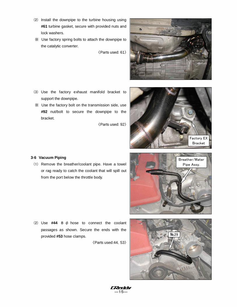
(2) Install the downpipe to the turbine housing using
#61 turbine gasket, secure with provided nuts and
lock washers.
※ Use factory spring bolts to attach the downpipe to
the catalytic converter.
〈Parts used: 61〉
(3) Use the factory exhaust manifold bracket to
support the downpipe.
※ Use the factory bolt on the transmission side, use
#92 nut/bolt to secure the downpipe to the
bracket.
〈Parts used: 92〉
3-6 Vacuum Piping
(1) Remove the breather/coolant pipe. Have a towel
or rag ready to catch the coolant that will spill out
from the port below the throttle body.
(2) Use #44 8 φ hose to connect the coolant
passages as shown. Secure the ends with the
provided #53 hose clamps.
〈Parts used:44,53〉
Factory EX
Bracket
Breather/Water
Pipe Assy.
№29
―16―
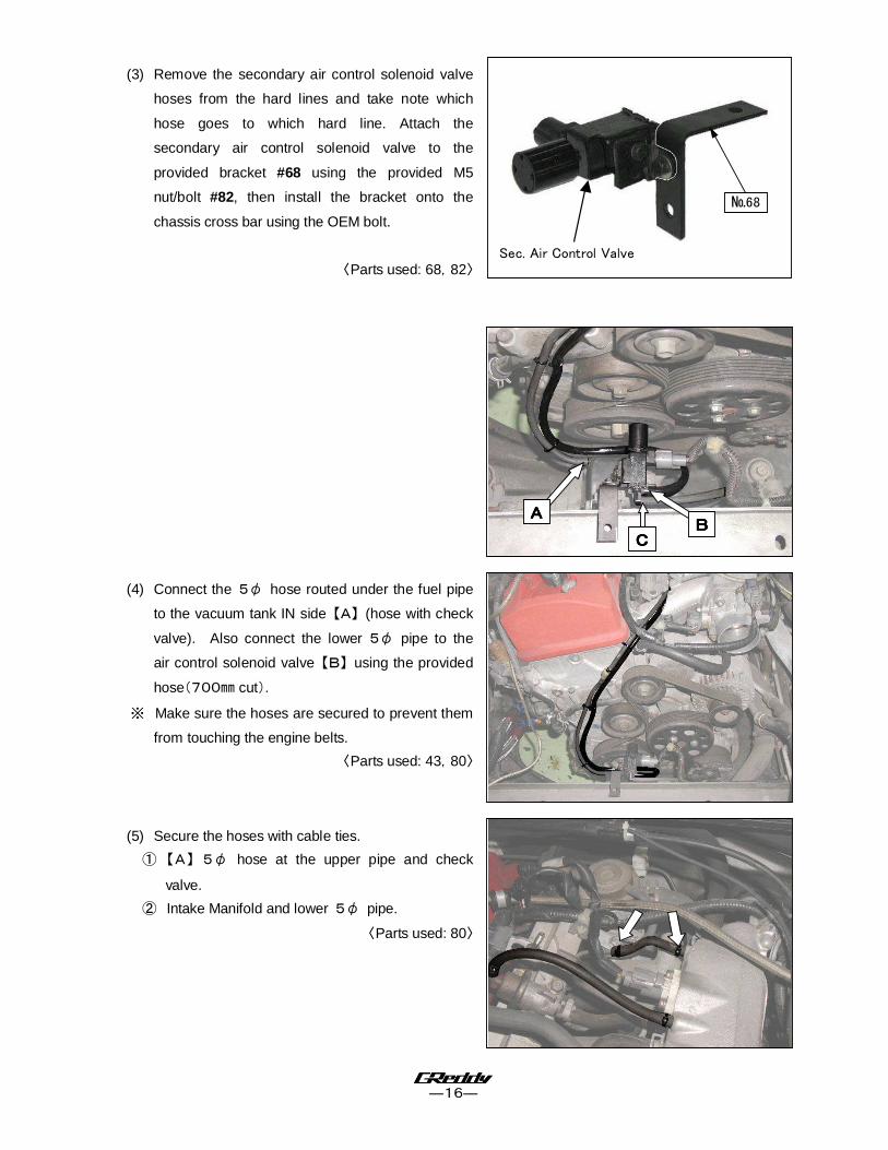
(3) Remove the secondary air control solenoid valve
hoses from the hard lines and take note which
hose goes to which hard line. Attach the
secondary air control solenoid valve to the
provided bracket #68 using the provided M5
nut/bolt #82, then install the bracket onto the
chassis cross bar using the OEM bolt.
〈Parts used: 68,82〉
(4) Connect the 5φ hose routed under the fuel pipe
to the vacuum tank IN side 【A】 (hose with check
valve). Also connect the lower 5φ pipe to the
air control solenoid valve 【B】 using the provided
hose(700㎜ cut).
※ Make sure the hoses are secured to prevent them
from touching the engine belts.
〈Parts used: 43,80〉
(5) Secure the hoses with cable ties.
① 【A】 5φ hose at the upper pipe and check
valve.
② Intake Manifold and lower 5φ pipe.
〈Parts used: 80〉
№68
Sec. Air Control Valve
AAAA
BBBB
CCCC
―17―
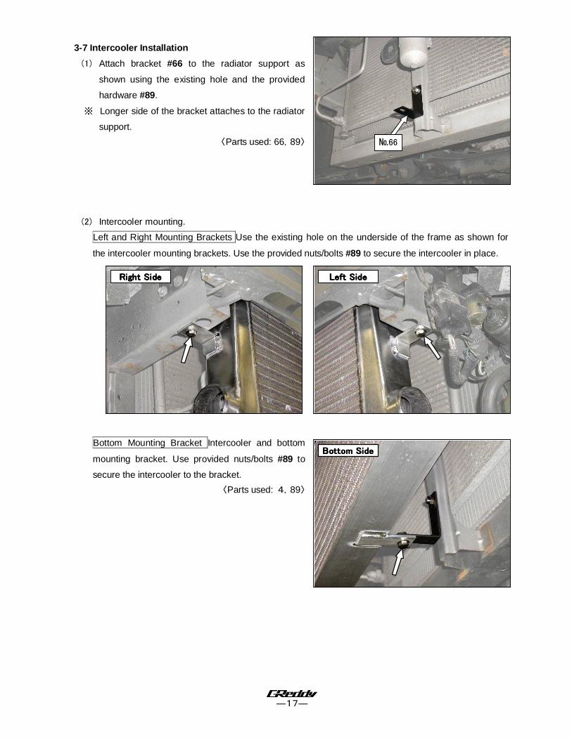
3-7 Intercooler Installation
(1) Attach bracket #66 to the radiator support as
shown using the existing hole and the provided
hardware #89.
※ Longer side of the bracket attaches to the radiator
support.
〈Parts used: 66,89〉
(2) Intercooler mounting.
Left and Right Mounting Brackets Use the existing hole on the underside of the frame as shown for
the intercooler mounting brackets. Use the provided nuts/bolts #89 to secure the intercooler in place.
Bottom Mounting Bracket Intercooler and bottom
mounting bracket. Use provided nuts/bolts #89 to
secure the intercooler to the bracket.
〈Parts used: 4,89〉
Right SideRight SideRight SideRight Side Left SideLeft SideLeft SideLeft Side
Bottom SideBottom SideBottom SideBottom Side
№66
―18―
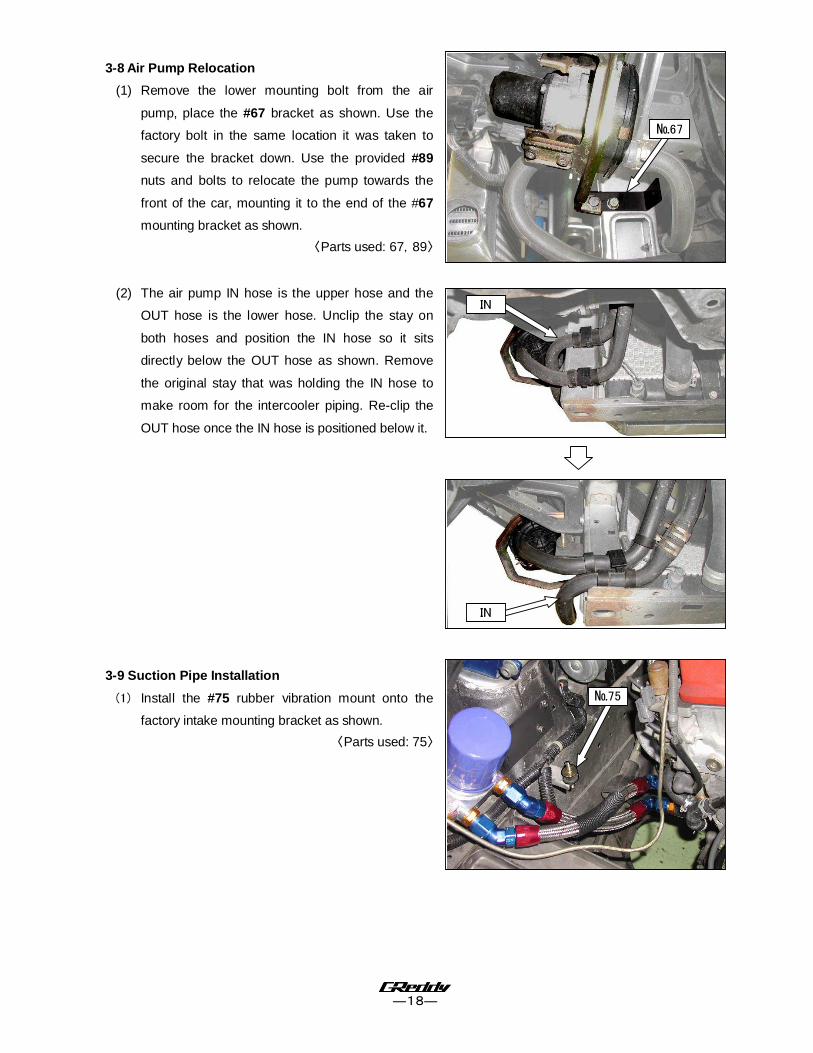
3-8 Air Pump Relocation
(1) Remove the lower mounting bolt from the air
pump, place the #67 bracket as shown. Use the
factory bolt in the same location it was taken to
secure the bracket down. Use the provided #89
nuts and bolts to relocate the pump towards the
front of the car, mounting it to the end of the #67
mounting bracket as shown.
〈Parts used: 67,89〉
(2) The air pump IN hose is the upper hose and the
OUT hose is the lower hose. Unclip the stay on
both hoses and position the IN hose so it sits
directly below the OUT hose as shown. Remove
the original stay that was holding the IN hose to
make room for the intercooler piping. Re-clip the
OUT hose once the IN hose is positioned below it.
3-9 Suction Pipe Installation
(1) Install the #75 rubber vibration mount onto the
factory intake mounting bracket as shown.
〈Parts used: 75〉
№75
№67
IN
IN

―19―
(2) Install suction pipe S-1 to the compressor housing
using the provided #62 gasket. Be sure that the
bracket on the pipe is positioned onto the rubber
vibration mount previously installed. Secure S-1 at
the compressor housing with the provided #90
hardware. Secure S-1 at the bracket and vibration
mount with the provided #87 nut.
〈Parts used: 5,62,87,90〉
Install the 12φoil resistant hose #45 from the valve
cover breather nipple to the nipple on the S-1 suction
pipe. Use provided hose clamps #54 to secure both
ends of the hose.
〈Parts used: 45,54〉
※ Install the provided 19φhose (#47) to the air
pump OUT hose using union #74. Secure the
other end of the hose to the suction pipe S-1. Use
provided #56 hose clamps to secure both ends of
the hose, as well as the end of the air pump OUT
hose (3 hose clamps used total).
〈Parts used: 47,56,74〉
№45
№47
№74
Zip Tie here
S-1 Rubber
Mount

―20―
3-10 Intercooler Piping
(1) Install #75 rubber vibration mount to the factory
hole on the chassis as shown.
〈Parts used: 75〉
(2) Install hose fitting 5 φ - 1 / 8 P T #73 to
compression pipe C-1.
※ Be sure to use Teflon tape on the threads of the
hose fitting.
〈Parts used: 6,73〉
(3) Cut provided vacuum hose to 200mm and route it
between the actuator and C-1 and secure the
hose with zip-ties.
〈Parts used: 43,80〉
(4) Install Compression tube C-1, C-2, C-3 from turbo to
intercooler inlet as shown. Use C-1 Gasket #63.
Compression Tube C-C-C-C-2222
Using the provided #87 flange nut, secure the
tube to the vibration rubber stub as shown.
Compression Tube C-C-C-C-3333
The shorter straight side is intercooler side.
〈Parts used No.6,7,8,48,49,51,57,58,63,87,90〉
№73
№75
C-2
C-1
C-2
C-3
C-2
C-3
Secure
here
―21―
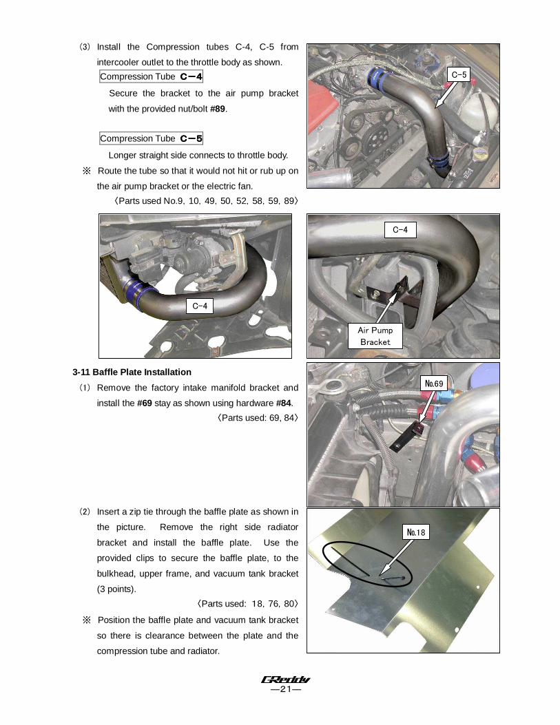
(3) Install the Compression tubes C-4, C-5 from
intercooler outlet to the throttle body as shown.
Compression Tube C-C-C-C-4444
Secure the bracket to the air pump bracket
with the provided nut/bolt #89.
Compression Tube C-C-C-C-5555
Longer straight side connects to throttle body.
※ Route the tube so that it would not hit or rub up on
the air pump bracket or the electric fan.
〈Parts used No.9,10,49,50,52,58,59,89〉
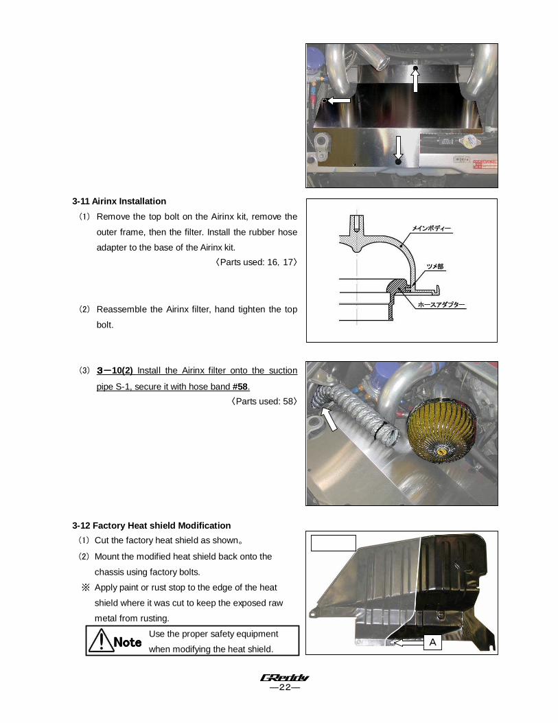
3-11 Baffle Plate Installation
(1) Remove the factory intake manifold bracket and
install the #69 stay as shown using hardware #84.
〈Parts used: 69, 84〉
(2) Insert a zip tie through the baffle plate as shown in
the picture. Remove the right side radiator
bracket and install the baffle plate. Use the
provided clips to secure the baffle plate, to the
bulkhead, upper frame, and vacuum tank bracket
(3 points).
〈Parts used: 18,76,80〉
※ Position the baffle plate and vacuum tank bracket
so there is clearance between the plate and the
compression tube and radiator.
№69
№18
Air Pump
Bracket
C-4
C-5
C-4
―22―
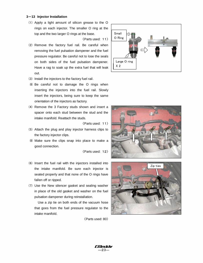
3-11 Airinx Installation
(1) Remove the top bolt on the Airinx kit, remove the
outer frame, then the filter. Install the rubber hose
adapter to the base of the Airinx kit.
〈Parts used: 16,17〉
(2) Reassemble the Airinx filter, hand tighten the top
bolt.
(3) 3333----10(2) Install the Airinx filter onto the suction
pipe S-1, secure it with hose band #58.
〈Parts used: 58〉
3-12 Factory Heat shield Modification
(1) Cut the factory heat shield as shown。
(2) Mount the modified heat shield back onto the
chassis using factory bolts.
※ Apply paint or rust stop to the edge of the heat
shield where it was cut to keep the exposed raw
metal from rusting.
Use the proper safety equipment
when modifying the heat shield.
NoteNoteNoteNote A
―23―
3----13 Injector Installation
(1) Apply a light amount of silicon grease to the O
rings on each injector. The smaller O ring at the
top and the two larger O rings at the base.
〈Parts used: 11〉
(2) Remove the factory fuel rail. Be careful when
removing the fuel pulsation dampener and the fuel
pressure regulator. Be careful not to lose the seals
on both sides of the fuel pulsation dampener.
Have a rag to soak up the extra fuel that will leak
out.
(3) Install the injectors to the factory fuel rail.
※ Be careful not to damage the O rings when
inserting the injectors into the fuel rail. Slowly
insert the injectors, being sure to keep the same
orientation of the injectors as factory.
(4) Remove the 3 Factory studs shown and insert a
spacer onto each stud between the stud and the
intake manifold. Reattach the studs.
〈Parts used: 11〉
(5) Attach the plug and play injector harness clips to
the factory injector clips.
※ Make sure the clips snap into place to make a
good connection.
〈Parts used: 12〉
(6) Insert the fuel rail with the injectors installed into
the intake manifold. Be sure each injector is
seated properly and that none of the O rings have
fallen off or ripped.
(7) Use the New silencer gasket and sealing washer
in place of the old gasket and washer on the fuel
pulsation dampener during reinstallation.
Use a zip tie on both ends of the vacuum hose
that goes from the fuel pressure regulator to the
intake manifold.
〈Parts used: 80〉
Zip ties
Oリング大×2
Small
O Ring
Large O ring
X 2
―24―
(8) Use the provided spacers under the brackets
marked A in the image (use on the intake manifold
side). Use the provided extended bolt in place of
the factory bolt to accommodate for the added
length.
〈Parts used: 11,86〉
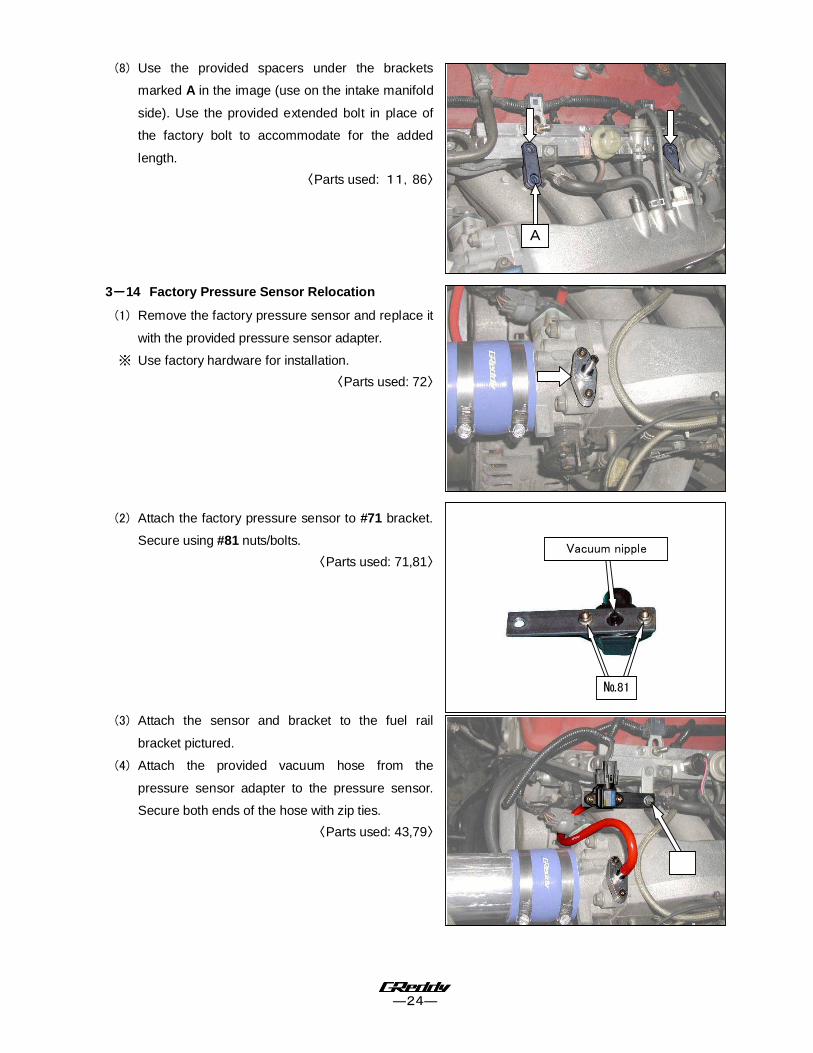
3----14 Factory Pressure Sensor Relocation
(1) Remove the factory pressure sensor and replace it
with the provided pressure sensor adapter.
※ Use factory hardware for installation.
〈Parts used: 72〉
(2) Attach the factory pressure sensor to #71 bracket.
Secure using #81 nuts/bolts.
〈Parts used: 71,81〉
(3) Attach the sensor and bracket to the fuel rail
bracket pictured.
(4) Attach the provided vacuum hose from the
pressure sensor adapter to the pressure sensor.
Secure both ends of the hose with zip ties.
〈Parts used: 43,79〉
A
Vacuum nipple
№81
―25―
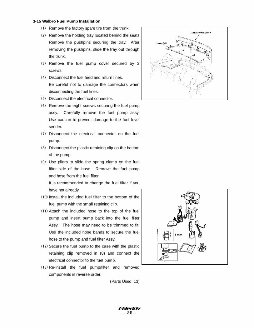
3-15 Walbro Fuel Pump Installation
(1) Remove the factory spare tire from the trunk.
(2) Remove the holding tray located behind the seats.
Remove the pushpins securing the tray. After
removing the pushpins, slide the tray out through
the trunk.
(3) Remove the fuel pump cover secured by 3
screws.
(4) Disconnect the fuel feed and return lines.
Be careful not to damage the connectors when
disconnecting the fuel lines.
(5) Disconnect the electrical connector.
(6) Remove the eight screws securing the fuel pump
assy. Carefully remove the fuel pump assy.
Use caution to prevent damage to the fuel level
sender.
(7) Disconnect the electrical connector on the fuel
pump.
(8) Disconnect the plastic retaining clip on the bottom
of the pump.
(9) Use pliers to slide the spring clamp on the fuel
filter side of the hose. Remove the fuel pump
and hose from the fuel filter.
It is recommended to change the fuel filter if you
have not already.
(10) Install the included fuel filter to the bottom of the
fuel pump with the small retaining clip.
(11) Attach the included hose to the top of the fuel
pump and insert pump back into the fuel filter
Assy. The hose may need to be trimmed to fit.
Use the included hose bands to secure the fuel
hose to the pump and fuel filter Assy.
(12) Secure the fuel pump to the case with the plastic
retaining clip removed in (8) and connect the
electrical connector to the fuel pump.
(13) Re-install the fuel pump/filter and removed
components in reverse order.
(Parts Used: 13)

―26―
3-16 Intake Duct Routing
(1) Remove the OEM air Diversion Panel.
(1) Position and route the intake ducting #77 as shown.
(2) Use the provided zip ties to secure the ducting onto the GReddy air diversion panel, and at the rear
of the intercooler.
〈Parts used: 77〉
―27―
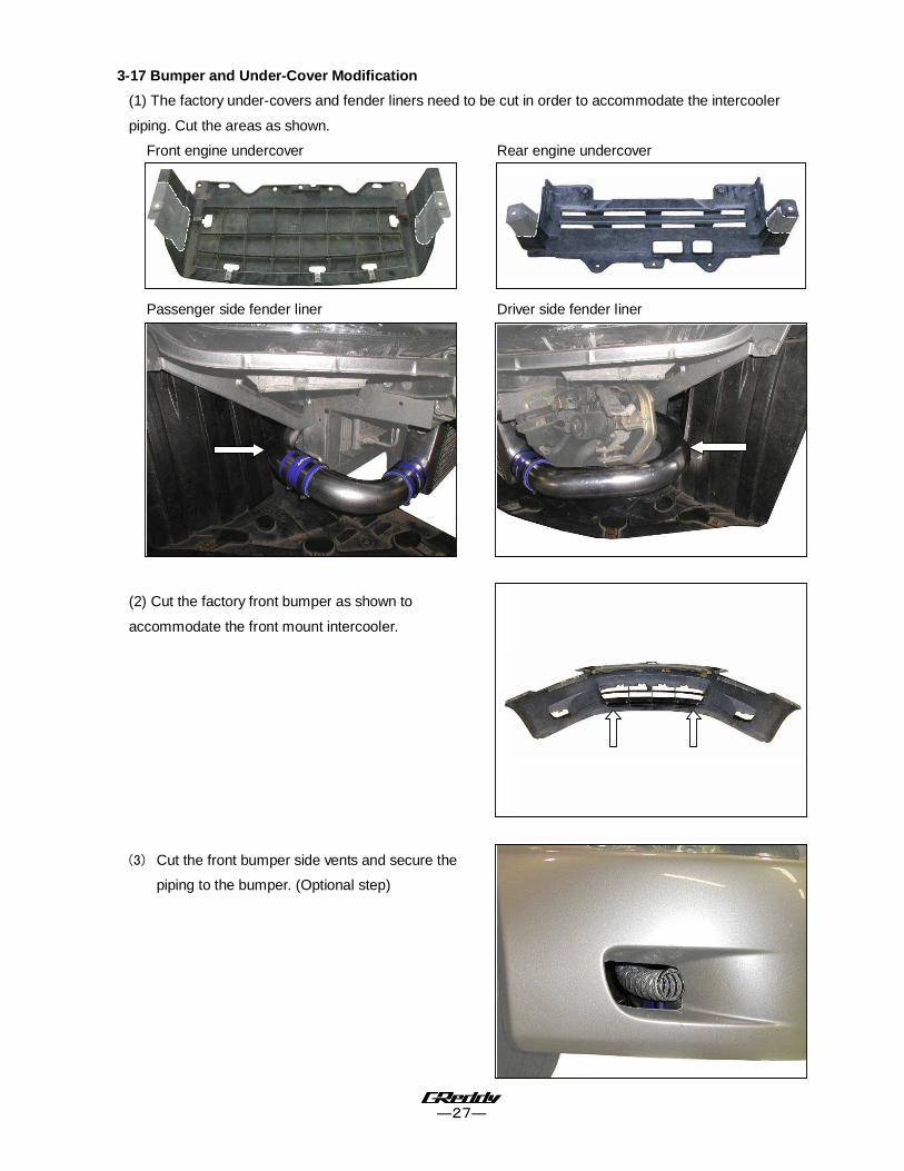
3-17 Bumper and Under-Cover Modification
(1) The factory under-covers and fender liners need to be cut in order to accommodate the intercooler
piping. Cut the areas as shown.
Front engine undercover Rear engine undercover
Passenger side fender liner Driver side fender liner
(2) Cut the factory front bumper as shown to
accommodate the front mount intercooler.
(3) Cut the front bumper side vents and secure the
piping to the bumper. (Optional step)

3-17 e-Manage Ultimate Installation
(1) Remove the driver side kick panel cover in order to access the ECU and ECU harness.
(2) Disconnect the ECU harness from the ECU.
(3) Connect the Emanage Ultimate Plug and Play Harness to the ECU and plug the stock ECU harness
into the Ultimate Plug and Play Harness.
(Parts used: 14, 15)
(4) Keep the Emanage Ultimate unit in a cool, dry place. Try not to cover it with any carpeting, and keep it
out of direct sunlight.
3-18 Starting the Engine
(1) Refill the engine oil to factory spec.
(2) Check all the hoses and wires connection and reconnect the negative side of the battery.
(3) Turn the ignition to “ON” position 2-3 times to get fuel pressure. Then, check the injectors and the fuel
rail for any fuel leaks.
* Repair any fuel leaks before starting the engine. Starting the engine with a fuel leak can cause
fire in the engine compartment and can be very dangerous.
(4) Remove the ECM fuse and crank the engine to get oil pressure to the turbo. (Until the oil light on the
dash turns off) Check for any oil leaks, then reinstall the fuse and start the engine.
(5) While idling, check for any oil, coolant, or air leaks.
(6) After inspection, reinstall the under cover and other stock parts that was removed.
(7) On the initial run, be sure to have a boost gauge to check the turbo-actuator setting. This turbo kit is preset
to boost between 0.50kg/cm2 to 0.55kg/cm2 ( 7 – 8 PSI ).
It is very important that you monitor the boost pressure, and make sure not to over boost. Over boosting can
cause engine damage.
This completes the Turbo Kit installation.
Important!
• It is very important that you monitor the boost pressure, and make sure not to over boost. Over
boosting can cause engine damage.
• GReddy Performance Products, Inc. is not responsible for any engine damage caused by over
boosting (increased boost), modification to the kit, and/or misuse of the product. NO WARRANTY is
offered.
• Due to lack of control over proper installation and use of this product,
NO WARRANTY is offered for this kit.
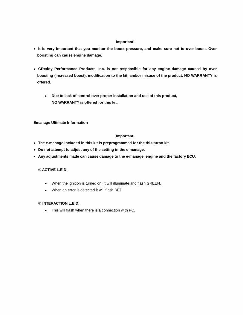
Emanage Ultimate Information
Important!
• The e-manage included in this kit is preprogrammed for the this turbo kit.
• Do not attempt to adjust any of the setting in the e-manage.
• Any adjustments made can cause damage to the e-manage, engine and the factory ECU.
� ACTIVE L.E.D.
• When the ignition is turned on, it will illuminate and flash GREEN.
• When an error is detected it will flash RED.
� INTERACTION L.E.D.
• This will flash when there is a connection with PC.
**IMPORTANT NOTE**
For GReddy turbochargers, GReddy Performance
Products, Inc. recommends the use of 100% FULLY
Synthetic Motor Oil made for turbochargers! The
use of improper oils may cause damage and shorten
the life of the turbocharger. GReddy Performance
Products, Inc. will not be held responsible for
damages due to the use of improper oil.


