Page 1
1
Green Preparation of PtRu and PtCu/SBA-15 Catalysts using
Supercritical CO2
E. Sánchez-Miguel, M.J. Tenorio, J. Morère and A. Cabañas*
Departamento de Química-Física I, Universidad Complutense de Madrid, 28040 Madrid.
SPAIN
*Send correspondence to:
Prof. Albertina Cabañas
Departamento de Química-Física I
Ciudad Universitaria s/n, 28040 Madrid SPAIN
Tlf: 34 + 91 3945225 Fax: 34 + 91 3944135
e-mail: [email protected]
Keywords: Supercritical fluids, Nanoparticles, Platinum, Supported Catalysts,
Hydrogenation
Page 2
2
ABSTRACT
Sustainability is emerging as design criteria in catalysts production. Hence, the preparation
of Pt bimetallic catalysts using supercritical CO2 (scCO2) as a green solvent is proposed. PtRu
and PtCu nanoparticles (NPs) were deposited on mesoporous SiO2 SBA-15 by the reduction
of Pt, Ru and Cu metalorganic precursor in scCO2. The simultaneous and sequential deposition
of both metals was attempted using different reduction methodologies. The materials were
characterized by X-Ray Diffraction (XRD), Transmission Electron Microscopy (TEM) and
Energy-Dispersive X-ray analysis (EDX). XRD patterns matched closely that of cubic Pt.
TEM images showed small NPs homogeneously distributed throughout the SBA-15
mesopores. Smaller particles were obtained when the reduction was performed in H2/N2 at
low pressure. Sequential deposition of Cu or Ru in the first place followed by Pt yielded
equimolar metal ratios. Samples prepared by sequential deposition were studied by Scanning
Transmission Electron Microscopy (STEM). Composition profiles of the PtRu samples
suggested an alloy structure. These catalysts were used in the hydrogenation of the renewable
furfural in scCO2 at 80ºC. PtRu materials presented a high activity and selectivity to furfuryl
alcohol.
Page 3
3
1. INTRODUCTION
Catalysts are essential in green chemistry research to reduce toxicity and increase chemical
reactions efficiency aiming for a sustainable development [1]. In particular, the catalytic
hydrogenation of organic molecules is of great importance in the pharmaceutical,
petrochemical and food industries. From a green chemistry viewpoint, using molecular
hydrogen increases the atom economy and at the same time it is considered a renewable
feedstock. Common hydrogenation catalysts are formed by Ni, Pd or Pt supported
nanoparticles (NPs). These materials generally lead to very high activities. Other metals such
as Ru or Cu are used when a high selectivity to intermediate forms or other interesting products
is sought. Bimetallic catalysts can show improved properties in comparison to monometallic
catalysts. The presence of two metals changes the electronic structure of the system and may
alter the activity and selectivity of the catalysts [2]. In the case of expensive noble metals, the
addition of a cheaper metal also offers economic advantages. Finally, controlling the metal
distribution on the NP (alloy structure, raspberry, core-shell,...), the catalytic activity can be
also changed.
Supported bimetallic NPs can be produced following conventional techniques such as wet
impregnation of the metal precursors followed by thermal or chemical reduction[3-5],
electroless deposition [6] and Chemical Vapour Deposition (CVD) [4]. Colloidal [7] and
reverse micelle [8] synthesis in which preformed nanoparticles are introduced into the support
are also currently used. Some of these methods offer the possibility to perform a sequential or
simultaneous deposition of the metals [3, 5]. Furthermore, for the simultaneous preparation, a
mixture of metal precursors or a bimetallic precursor can be used [9]. When the deposition of
each metal is performed sequentially, several techniques can be combined [10].
Page 4
4
If the process is carried out in a liquid solvent, the large viscosity and surface tension of
most liquid solvents may cause the slow diffusion of the metal precursor or metal
nanoparticles within the support pores leading to poorly dispersed and non-homogeneous
materials. The drying process may also cause structural changes into the catalyst with a
significant reduction of the support surface area and catalytic activity. On the other hand, gas
phase processes such as CVD are generally limited by the low vapour pressure of the metal
precursors and may not be suitable for preparation of homogeneous bimetallic materials with
high metal loadings. Therefore conventional methods may lead to inhomogeneous materials
of not well defined composition and structure and a broad particle size distribution. Moreover,
some of these methods require the use of toxic solvents and or reagents and are multistep
processes.
Supercritical CO2 (scCO2) has been proposed as a green solvent in the catalysts
preparation following the Supercritical Fluid Deposition (SCFD) technique [11]. CO2 used
is obtained as a sub-product of many industrial processes, and there is large interest in its
utilization. The CO2 moderate critical temperature and pressure (Tc = 31.0 ºC, Pc = 7.38 MPa)
[12], its non-toxicity and non-flammability turn it into an excellent candidate to replace toxic
organic solvents. Furthermore it is a gas at atmospheric pressure and does not leave any
residue. The low viscosity, high diffusivity and very low surface tension of supercritical CO2
and its high solvating power favour the penetration of metal precursors dissolved in scCO2
within the catalyst support and at the same time avoid damage in the pore structure. The
impregnated support is then reduced leading to metal NPs dispersed on the support. Different
metals or metal oxides nanoparticles have been deposited on organic and inorganic substrates
using scCO2 [12-14]. Nanoparticle size distribution depends on concentration, reduction
Page 5
5
methodology and substrate [15]. Controlling the size, composition and morphology of the
nanoparticles, their catalytic activity and selectivity can be tuned [16].
The deposition of bimetallic NPs onto different supports has been also addressed and
reviewed by Bozbag and Erkey [14]. Supported metal NPs of PtRu, PtPd, PtCu, PtNi and
PtAu, have been previously prepared using scCO2. Apart from a very recent report by Qiao et
al. on the deposition of PtPd NPs on mesoporous SiO2 supports [17], bimetallic Pt NPs were
deposited on carbon based supports such as carbon nanotubes (CNTs) [14, 18, 19], carbon
black [14] and, recently, on functionalized graphene sheets [20] for catalytic applications.
Lang et al. have also reported the preparation of PtCuO/CeO2/-Al2O3 catalysts [21]. Pt/SnO2
catalysts were also supported on Al2O3 foams [22]. With respect to the methodology, in most
cases the simultaneous reduction of the metal precursors was carried out in H2/CO2 mixtures.
Müller and Türk have successfully deposited AuAg core-shell structures following this
methodology [23]. Prof. Erkey and coworkers have also studied the impregnation of both
metal precursors on the support followed by thermal decomposition at ambient pressure and
proposed the sequential deposition of both metals [14].
In this work, the preparation of PtRu and PtCu bimetallic NPs supported on mesoporous
SiO2 SBA-15 (SBA-15) using scCO2 is studied. The utilization of CO2 as solvent and reaction
medium in the catalysts preparation may lead to very homogeneous materials. The effect that
the reduction methodology has on the chemical composition, structure of the bimetallic
material and their catalytic properties is addressed in this paper for the first time.
SBA-15 shows high thermal and chemical stability along a high surface area and an
uniform pore size distributions. The support helps to stabilize the nanoparticles, preventing
Page 6
6
their sintering and aggregation and, at the same time, facilitates handling of the catalyst. The
addition of Ru or Cu to Pt, reduces the cost of the catalyst and may allow a higher selectivity
in hydrogenation reactions in comparison to Pt.
As a model reaction to test the materials prepared in scCO2, the hydrogenation of furfural
is proposed. Furfural is an important renewable, non-petroleum based, chemical feedstock,
which is produced from lignocellulosic residues (agricultural by-products like sugarcane,
bagasse and corn cobs). It is considered a potential platform chemical [24] because it can be
readily hydrogenated to other value added chemicals such as furfuryl alcohol, 2-methylfuran
and the corresponding tetrahydrofuran derivatives, among others.
Different Pd, Pt, Ru, Cu and Pt bimetallic supported based catalysts have been proposed in
the hydrogenation of furfural [25, 26]. Furthermore, the hydrogenation of furfural has been
performed in scCO2 [26, 27]. The tuneable solvent properties and green nature of scCO2
provide a very interesting medium for chemical reactions. Furfural and the possible products
are highly soluble in CO2 and H2/CO2 mixtures at supercritical conditions and the reaction can
be performed in the one-phase region. Stevens et al. have shown that by a right combination
of catalyst and temperature, a fine control of the product distribution can be achieved [27].
In this work we study the preparation of Pt bimetallic catalysts in scCO2 and its use in the
hydrogenation of furfural as a model reaction. The effect that the presence of the two metals
and the preparation method has on the catalytic properties of these materials is studied. Both
the catalyst preparation and the catalytic reaction are carried out in scCO2, using a renewable
feedstock making the whole process sustainable.
2. MATERIALS AND METHODS
2.1 Materials
Page 7
7
The precursors dimethyl(1,5-cyclooctadiene)platinum(II) [Pt(CH3)2(cod)] (97%) and
bis(2,2,6,6-tetramethyl-3,5-heptanodionato)(1,5-cyclooctadiene) ruthenium(II),
[Ru(tmhd)2(cod)] (99%) and bis(2,2,6,6-tetramethyl-3,5-heptanodionate) copper (II)
(Cu(tmhd)2) (99%) were provided by Strem Chemicals. Tetraethylorthosilicate (TEOS,
>99+% pure), poly(ethylene glycol)-block-poly(propylene glycol)-block-poly(ethylene
glycol) (Mw=5800) (PEO-PPO-PEO), furfural (99 %), 1,5-pentanediol (+97%, GC) and
dichloromethane (99.9%, GC) were purchased from Sigma Aldrich. Furfuryl alcohol (98%),
tetrahydrofurfuryl alcohol (+97%), 2-methyltetrahydrofurane (+99%) and 2-methylfuran
(99%) were supplied by Acros Organics. All chemicals were used as received. CO2 (purity
>99.99%) and H2 (purity >99.999%) were supplied by Air Liquide. H2(5%)/N2 was supplied
by Contse. Mesoporous silica SBA-15 was synthesized following a procedure similar to that
described by Zhao et al.[28, 29] using PEO-PPO-PEO as structure-directing agent and TEOS
as precursor.
Page 8
8
The physical properties of the metal precursors are given in Table 1.
Table 1. Physical properties of the metal precursors: molar mass (M), % metal wt and melting
temperature (Tm)
Metal Precursor M (g/mol) % metal wt Tm (ºC) Ref.
Pt(cod)(CH3)2 333.3 58.5 105 [30]
Ru(tmhd)2(cod) 575.8 17.5 187-190 http://www.strem.com
Cu(tmhd)2 430.8 14.8 198 http://www.strem.com
2.2 Materials preparation
Catalysts were prepared using a 100 mL stirred high-pressure Bolted Closure reactor
(Autoclave Eng.) or a 60 mL custom made high-pressure stainless steel reactor heated with a
small furnace provided with magnetic stirring. CO2 was introduced into the reactor using a
high pressure syringe pump (ISCO 260D), thermostated at 60-80 ºC, depending on the
experiments. When necessary, H2 was introduced into the reactor using a 30 mL high-pressure
auxiliary cell.
The SCFD comprises three different steps: (i) dissolution of the metal precursors in scCO2
at a given conditions, (ii) adsorption of the precursor on the support from the fluid phase and
(iii) precursor decomposition to the metal form.
A metal precursor or a mixture of the two metal precursors at the same molar concentration
(1:1 molar ratio) and a given amount of support were placed into the reactor. Maximum metal
loading for each metal relative to the support was 2% mol, which represents metal mass
percentages of 6.2, 3.3 and 2.1 % wt for Pt, Ru and Cu, respectively. The reactor was then
Page 9
9
heated up to the selected temperature and was filled with CO2 from the thermostated syringe
pump at a given pressure. The precursor dissolved in scCO2 and adsorbed onto the support.
The adsorption equilibrium is governed by the relative affinity among precursors-CO2
(solubility of each precursor), precursor-support (precursor adsorption) and CO2-support (CO2
adsorption) and can be tuned with the precursor concentration, pressure and temperature. In
this work, the impregnation step for Pt and Cu precursors (either separated or mixed) was
carried out at 60 ºC and 13.0 MPa, whilst for pure and mixed metals containing Ru,
impregnation was performed at 80 ºC and 13.5 MPa and 60 ºC and 13.0 MPa (see Table 2).
Conditions were selected based on previous results [31, 32]. Impregnation time varied from
1-4 hours.
The concentration of each metal precursor in CO2 was ca. 3.5 10-5 in mole fraction. Mole
fraction solubility of Pt(cod)(CH3)2 and Cu(tmhd)2 in CO2 at 60 ºC and 13.0 MPa were ca. 5.2
10-4 and 3.02 10-4, respectively [33], whilst the estimated solubility of Ru(tmhd)2(cod) in CO2
at 80 ºC and 13.0 MPa was 9.9 10 -5 [33]. Therefore, precursors were fully soluble at the
impregnation conditions.
The metal precursors adsorbed on the support were reduced to the metal form following:
chemical reduction with H2 in the supercritical mixture (reactive deposition, RD) or chemical
reduction in H2(5%)/N2 flow at low pressure in a tubular furnace (impregnation/reduction,
IR). Scheme 1 summarizes the methods used.
Page 10
10
Scheme 1. Methodologies employed in the Supercritical Fluid Deposition (SCFD) of metal
nanoparticles. The first step involving the precursor dissolution in scCO2 and the
impregnation of the support is common to both and it is followed by: (a) despressurization
and reduction in H2/N2 (impregnation/reduction, IR) or (b) reactive deposition in H2/scCO2
at high temperature (reactive deposition, RD).
In the reactive deposition, H2 was introduced into the reactor containing the supercritical
mixture and the temperature was risen. Precursor reduction was carried out in H2/scCO2 at
80ºC and 18.0 MPa (Pt) or 150-200 ºC and ca. 30.0 MPa (Ru, Cu and the Pt bimetallics) for 1
hour. In the impregnation/reduction, reduction was performed after depressurization at
atmospheric pressure in H2/N2 atmosphere and a tubular furnace at 200ºC (Pt) or 400ºC (Ru,
Cu and the Pt bimetallics) for 4 hours.
Page 11
11
Scheme 2- Simultaneous and sequential deposition of bimetallic compounds by the
Supercritical Fluid Deposition (SCFD). Each step can be performed by
impregnation/reduction or reactive deposition following Figure 1.
Both, the simultaneous impregnation of the two metals and the sequential deposition of
each metal were attempted, following the methodologies described previously (Scheme 2).
The simultaneous deposition involves the addition of both metal precursors simultaneously to
the reactor. On the other hand, the sequential methodology (s) consists on depositing the first
metal (M1) as a seed and, on a second step, depositing the second metal (M2) leading to M1M2.
The order of deposition of each metal was varied. These materials are referred as PtRu(s),
RuPt(s), PtCu(s) and CuPt(s). Furthermore the reduction was performed following reactive
deposition or impregnation on each step as previously described, giving rise to many different
combinations. Pressure and temperature conditions used in each methodology for each metal
or bimetallic mixture are summarized in Table 2.
Page 12
12
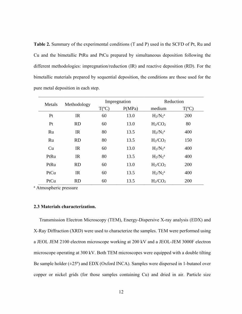
Table 2. Summary of the experimental conditions (T and P) used in the SCFD of Pt, Ru and
Cu and the bimetallic PtRu and PtCu prepared by simultaneous deposition following the
different methodologies: impregnation/reduction (IR) and reactive deposition (RD). For the
bimetallic materials prepared by sequential deposition, the conditions are those used for the
pure metal deposition in each step.
a Atmospheric pressure
2.3 Materials characterization.
Transmission Electron Microscopy (TEM), Energy-Dispersive X-ray analysis (EDX) and
X-Ray Diffraction (XRD) were used to characterize the samples. TEM were performed using
a JEOL JEM 2100 electron microscope working at 200 kV and a JEOL-JEM 3000F electron
microscope operating at 300 kV. Both TEM microscopes were equipped with a double tilting
Be sample holder (±25º) and EDX (Oxford INCA). Samples were dispersed in 1-butanol over
copper or nickel grids (for those samples containing Cu) and dried in air. Particle size
Metals Methodology Impregnation Reduction
T(ºC) P(MPa) medium T(ºC)
Pt IR 60 13.0 H2/N2a 200
Pt RD 60 13.0 H2/CO2 80
Ru IR 80 13.5 H2/N2a 400
Ru RD 80 13.5 H2/CO2 150
Cu IR 60 13.0 H2/N2a 400
PtRu IR 80 13.5 H2/N2a 400
PtRu RD 60 13.0 H2/CO2 200
PtCu IR 60 13.5 H2/N2a 400
PtCu RD 60 13.5 H2/CO2 200
Page 13
13
distribution was obtained from the TEM images. Metal loading of all the samples was
measured by EDX. The JEOL 3000F microscope was used in the Scanning Transmission
Electron Microscopy (STEM) mode, using the EDX analysis to determine the architecture of
the bimetallic NPs. For the RuPt and the CuPt samples, samples were carbon coated before
analysis in an effort to improve stability under the electron beam. Wide angle XRD patterns
of the composite materials were collected using a X´PERT MPD diffractometer with Cu Kα
radiation at 2θ values between 10 and 90º. The Scherrer equation was employed to estimate
the crystallite size.
2.4 Catalytic tests
Catalytic test were performed in the batch mode. A given amount of the furfural and the
catalyst with a molar ratio substrate to metal equal to 200:1 and a stirring bar were placed in
a 60 mL high-pressure stainless-steel reactor. The reactor was provided with a custom made
heating aluminum jacket. No prior activation of the catalysts was performed. The system was
sealed and purged with CO2 at low pressure several times. Then the reactor was heated at 80
ºC and CO2 was added to the reactor from a thermostated ISCO syringe pump at the same
temperature up to a total pressure of 10.0 MPa. Afterwards 4-6 MPa H2 depending on the
experiment, were added from a 30 mL high-pressure auxiliary cell to the reactor by flowing
CO2 through the cell to the reactor up to a final pressure of 18.0 MPa. Contents of the cell
were stirred with a magnetic stirrer. The H2 to furfural molar ratio was 25:1. Reaction time
was measured after the H2/CO2 addition once the reaction conditions were reached. Samples
were taken using a high-pressure 6-way valve (Valco) with a 500 L loop at regular times
from 30 to 180 min. The reaction was terminated by placing the reactor into a water/ice bath,
Page 14
14
followed by depressurization over a small amount of dichloromethane and further washing the
reactor with more dichloromethane. The solid catalyst was separated from the reaction mixture
by filtration.
The products were analyzed using a Shimadzu 2010 Plus gas chromatograph equipped with
a Flame Ionization Detector (FID) and a Zebron ZB-1HT capillary column (20 m x 0.18 mm
i.d. x 0.18 m film thickness). N2 was used as carrier gas and flowed at 30 mL/min. The
column temperature was initially held at 60 ºC for 4 min, then ramped at 20 ºC min-1 to 200
ºC and then held at this temperature for 3 min. Injector and detector temperature was 250 ºC
with a split ratio of 300. Peak assignments were confirmed with standard samples of
commercially available compounds. Quantification was performed by integrated peak area
normalization.
3. RESULTS AND DISCUSSION
3.1 Metal Deposition
Deposition of PtRu and PtCu NPs into mesoporous silica SBA-15 was carried out following
both reduction methodologies: impregnation/reduction and reactive deposition (Scheme 1)
and the simultaneous and sequential deposition (Scheme 2). The precursor molar ratio was
1:1. For comparison purposes Pt, Ru and Cu NPs were also successfully deposited on SBA-
15.
Page 15
15
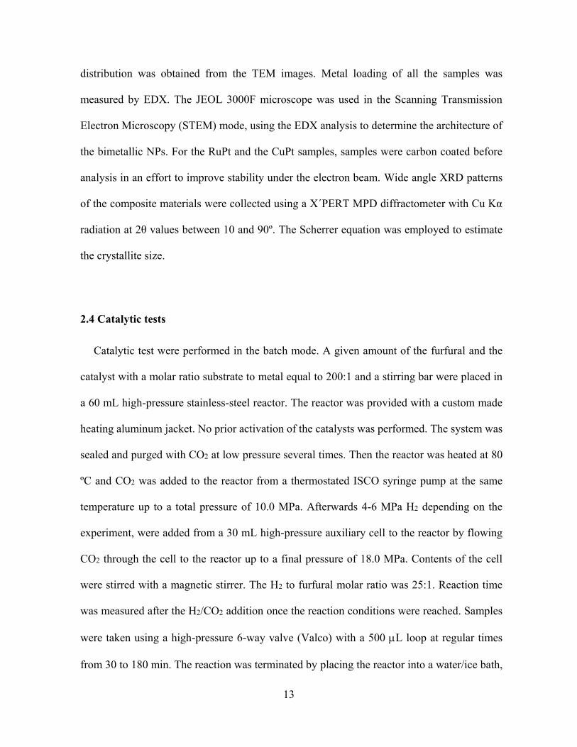
XRD patterns of the PtRu and PtCu bimetallic materials prepared are shown in Figures 1
and 2, respectively. Figure 1 also shows the XRD pattern of pure Pt. The wide signal centered
at 2 ~22º is ascribed to the mesoporous SiO2 support. Further peaks at 39.8º, 46.2º, 67.5º and
81.3º fit to the (111), (200), (220) and (311) reflections of cubic Pt (PDF 040802). Due to the
low metal concentration and small particle size, XRD patterns for pure Ru and Cu did not
show clear reflection.
Figure 1. XRD patterns of the PtRu bimetallic samples on SBA-15 prepared by SCFD: (a)
PtRu RD, (b) PtRu IR, (c) PtRu(s) RD-RD, (d) RuPt(s) IR-RD, (e)RuPt(s) IR-IR and (f) Pt IR
Page 16
16
Figure 2. XRD patterns of the PtCu bimetallic samples on SBA-15 prepared by SCFD: (a)
PtCu RD, (b) PtCu IR, (c) PtCu(s) RD-RD, (d) CuPt(s) IR-RD and (e) CuPt(s) IR-IR.
For compositions less than 60% mol Ru, the PtRu bulk phase diagram[34] show the
formation of substitutional solid solutions (disordered structures or alloys) in which the Pt
cubic structure is maintained and some Pt atoms are replaced by the smaller Ru atoms.
Therefore, typical Pt alloys show a slight shift of the diffraction peaks maxima [18-20, 35,
36]. Similarly, PtCu bulk phase diagram[37] show, at high T, the formation of continuous
cubic solid solutions. At lower temperatures, however, several ordered structures or
intermetallic compounds are reported. On the other hand, the stabilization of different
structures from the bulk in bimetallic NPs has been also reported.[38] For both PtRu and PtCu
NPs deposited in scCO2, XRD patterns suggest the formation of a cubic alloy type of structure.
However, it is difficult to assert the shift of the diffraction peaks at higher 2values from the
original Pt structure, particularly for the samples deposited by sequential deposition. This
Page 17
17
could be due in part to the small Ru and Cu content in the samples in comparison to Pt, related
to their lower metal molecular mass.
Selected PtCu and CuPt samples were annealed at 600 and 900ºC in H2/N2 in a tubular
furnace for 3 hours. Peak position of the (111) reflection for cubic Pt shifted slightly to larger
2 values after annealing particularly in the samples deposited by sequential deposition. The
largest shift was observed for the CuPt(s) IR-RD sample in which Pt was deposited on a Cu
seed at 80ºC. The low temperature employed in the Pt deposition may have produced a core-
shell structure. Alloying of the metals was promoted with annealing. (See Supplementary
Material).
Particle size of the different samples as-prepared estimated from the fit of the (111) Pt peak
to the Scherrer equation are also given in Table 3. XRD peaks for the PtCu sample prepared
by IR were too weak to perform this estimation.
Transmission Electron Microscopy (TEM) images of the different samples are shown in
Figures 3 to 5. TEM images showed the cylindrical pores of the SBA-15 support along with
the metal NPs. The size of the support pores is between 6-7 nm, which agrees well with the
pore size determined from N2-adsorption (6.4 nm) [39]. Average particle sizes obtained from
the TEM images are reported in Table 3.
The ordered structure of the porous support was confirmed by small angel XRD. Deposition
of Pd on SiO2 SBA-15 using scCO2 showed that the porous structure and ordering of the
support were preserved after the deposition process, with no change on the cell parameters
[40].
Page 18
18
Table 3. Summary of the metal deposition experiments by SCFD, showing the methodology:
impregnation/reduction (IR) and reactive deposition (RD) for 1:1 initial metal molar ratios.
For the sequential deposition (s), depending on the order of deposition, samples are named
PtRu(s) or RuPt(s) and PtCu(s) or CuPt(s). M1 and M2 molar metal loads on SBA-15 and
M1:M2 metal molar ratio were measured by EDX. Average crystallite size was estimated from
the XRD patterns applying the Sherrer equation to the Pt (111) peak. Particle size averages
were determined from the particle size distribution measured from TEM.
Sample
M1M2 Method
Molar
Ratio
M1:M2
Metal on SiO2
(% mol)
Scherrer
Crystallite
size (nm)
TEM
Particle size
(nm) M1 M2
PtRu IR 60:40 1.6 1.2 4.7 4.60.5
PtRu RD 70:30 1.2 0.49 5.8 5.70.6
PtRu(s) RD-RD 60:40 1.6 1.2 5.5 8.71.2*
RuPt(s) IR-IR 55:45 1.8 1.4 3.2 3.50.6
RuPt(s) IR-RD 50:50 1.8 1.8 5.1 4.60.5
PtCu IR 70:30 1.6 0.73 - 4.80.6
PtCu RD 85:15 1.6 0.33 8.4 10.70.7*
PtCu(s) RD-RD 70:30 1.6 0.61 5.0 5.00.4
CuPt(s) IR-IR 45:55 1.6 1.9 4.5 4.60.5
CuPt(s) IR-RD 50:50 1.6 1.6 5.6 4.10.5
*Rod-like particles. The size indicates the rod length and the diameter is ca. 7 nm.
Page 19
19
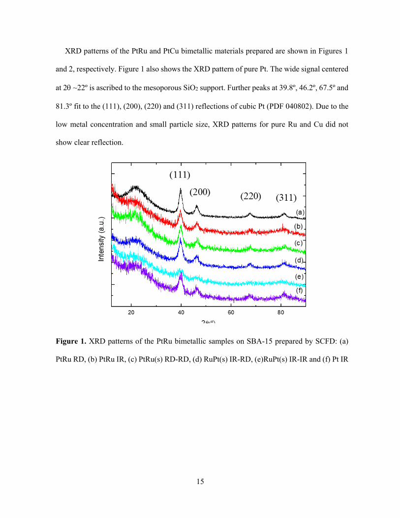
Figure 3. TEM images of metal samples on SBA-15 prepared by SCFD and
impregnation/reduction: (a) Pt, (b) Ru (c) Cu.
TEM images of the Pt, Ru and Cu NPs obtained by the impregnation/reduction
methodology are shown in Figure 3. Previous results showed that smaller particles were
obtained when this methodology is used [26, 27]. Pt and Ru NP of 3-4 nm size were clearly
located inside the SBA-15 mesopores. Particles were homogeneously distributed throughout
the support pores. Cu NPs deposited on SBA-15 were much smaller and almost imperceptible
by TEM (Figures 3c-d). Pt, Ru and Cu metal loads on SBA-15 determined by EDX on the
TEM images varied from 1.6 to 2.0% mol. At the impregnation conditions (see Table 2 in
experimental section), Ru and Cu precursors seem to adsorb less strongly to the silica support
than the Pt precursor leading to slightly lower loads.
Page 20
20
Figure 4. TEM images and Pt to Ru or Pt to Cu molar ratios for the bimetallic samples on
SBA-15 prepared by SCFD simultaneous deposition: (a) PtRu IR, (b) PtCu IR (c) PtRu RD
and (d) PtCu RD.
TEM images of the different bimetallic samples are shown in Figures 4 and 5. Samples
prepared by impregnation/reduction showed small metal particles mostly spherical confined
into the SiO2 mesopores, which do no aggregate. When the reactive deposition was used,
particle size distribution broadened and elongate particles were obtained.
Spherical PtRu particles were deposited by impregnation/reduction with an average size of
4.7 nm (Figure 4a). The PtRu material obtained by reactive deposition however showed larger
particles of 5.7 nm average and a broader particle size distribution (4-8 nm) (Figure 4c).
Similarly, PtCu NPs deposited by reactive deposition were much larger than those
deposited by impregnation/reduction. The PtCu sample obtained by impregnation/reduction
Page 21
21
(Figure 4b) exhibited a bimodal particle size distribution with very small particles between 1-
2 nm and larger elongated particles of ca. 4.8 nm. This may suggest at least partial segregation
of the metals on the support [31]. In comparison, the PtCu NPs prepared by reactive deposition
became rods of 7 nm diameter and lengths up to 18 nm (figure 4d), with an average size of
10.7 nm. Estimates obtained applying the Scherrer equation showed the same trend, with
values always smaller for the samples prepared by impregnation/reduction. As expected, for
the PtCu RD rod-like particles, differences between the particle size and the crystallite size
from XRD were larger.
Although the temperature used in the reactive deposition experiments of the bimetallic
materials (200ºC) was generally lower than the temperatures employed in the reduction step
of the impregnation/reduction methodology (200-400ºC), particles obtained by reactive
deposition grew larger. In the impregnation/reduction methodology, the organometallic
compounds are reduced and the ligands decomposed to be removed from the surface, whilst
in the reactive deposition, the precursors are only hydrogenated and the ligands solubilized in
scCO2. Therefore reduction temperatures are generally lower in H2/scCO2. However, when
the simultaneous reactive deposition was performed, Pt was probably reduced first and could
catalyze afterwards the reduction of Ru or Cu.
Bimetallic NPs were always much larger than the monometallic ones. This is partially due
to the larger total metal loads and to the higher temperatures used in the reduction step of the
bimetallic samples in comparison to those of pure Pt (see Table 2).
Average metal loadings estimated from Energy-Dispersive X-ray (EDX) analysis are given
in Table 3 and Figures 4 and 5. Pt to Ru metal molar ratios equal to 70:30 and 60:40 were
obtained by reactive deposition and simultaneous impregnation/reduction, respectively.
Page 22
22
Simultaneous deposition of PtCu was however more complex and led to Cu loads much lower
than the expected one, and Pt to Cu molar ratios of 85:15 and 70:30 obtained by simultaneous
reactive deposition and impregnation/reduction, respectively. The larger incorporation of Pt
in all the samples is due to the stronger interaction of the Pt precursor with the SBA-15 support
in comparison to that of the Ru and Cu precursors. Higher metal loadings and metal molar
ratios closer to the initial ones were obtained by impregnation/reduction, which suggest the
partial reduction of both precursors in the supercritical phase in the reactive deposition.
TEM images of the bimetallic NPs deposited on SBA-15 by sequential deposition are
shown in Figure 5. Preparation of PtRu(s) and PtCu(s) was performed sequentially depositing
Pt in the first place, followed by reactive deposition of Ru or Cu. We chose this methodology
because of the lower temperature and shorter time employed, with the aim to promote core-
shell structures. PtRu(s) particles grew larger and became slightly elongated (Figure 5a), with
an average length of 8.7 nm. In the PtCu(s) sample (Figure 5b), however, particles were much
smaller than those obtained in the PtRu(s) sample (5.0 nm). EDX analysis of the PtRu(s) and
PtCu(s) samples did not lead to the 1:1 molar metal ratio; 60:40 and 70:30 molar ratios were
obtained, respectively. Considering than the Pt seed used in both experiments is the same, the
lower incorporation of Cu in PtCu(s) may partly explain the lower particle size.
Page 23
23
Figure 5. TEM images and molar ratios (M1 to M2) of bimetallic samples (M1M2) on SBA-15
prepared by SCFD sequential deposition: (a) PtRu(s) RD-RD, (b) PtCu(s) RD-RD, (c) RuPt(s)
IR-IR, (d) CuPt(s) IR-IR (e) RuPt(s) IR-RD and (f) CuPt(s) IR-RD.
Then the order in the metal deposition was changed and RuPt(s) and CuPt(s) samples were
prepared. In the RuPt(s) and CuPt(s) samples, deposition of the first metal (Ru or Cu) was
always performed by impregnation/reduction in order to get the smallest particles. Then Pt
Page 24
24
was deposited onto the Ru or Cu NPs through either impregnation/reduction or reductive
deposition. In both cases, TEM images showed a large number of spherical NPs
homogeneously distributed into the SBA-15 mesopores. Particles did not aggregate. No much
differences in the particle sizes were found between the RuPt(s) and CuPt(s) samples prepared
sequentially and the different methodologies used to deposit the second metal. Average sizes
ranging from 3.5 to 4.6 nm were obtained (Figures 5c-f). Interestingly, whilst for RuPt(s)
particles grew larger when Pt was deposited by RD (Figure 5e), for CuPt(s), average particle
size was slightly smaller in this case (Figure 5f). For this sample, a higher magnification TEM
image shows the presence of very small particles, which broaden the particle size distribution
and shift the average size to lower values.
In both cases, EDX analysis showed molar metal ratios very close to the 1:1 ratio. By
depositing Cu or Ru in the first place, the incorporation of these metals to the system is favored
and the final metal ratio in the NPs is closer to the equimolar ratio.
For the sequential deposition experiments, samples were studied by STEM. STEM-EDX
images in Z contrast are shown in Figure 6 for PtRu(s) RD-RD (Ru over a Pt seed).
Composition analysis for this sample did not show a core-shell structure and overlapping of
the Pt and Ru signals along each particle were observed, which suggested an alloy type
structure. Ru precursor was reduced on the Pt seed at 200ºC for 1 hour.
Page 25
25
Figure 6. STEM image of PtRu(s) RD-RD on SBA-15 in Z contrast. Composition profiles
(right) along single NPs are presented, showing the relative abundance of Pt in red and Ru in
blue (arbitrary units).
Analysis of the RuPt(s) and CuPt(s) samples deposited on SBA-15 by the same technique
was unsuccessful due to the smaller particle size and the instability of the samples to the
electron beam that drifted the sample during the EDX analysis. Considering that in the
sequential deposition, Pt was deposited at very low temperature by reactive deposition (80ºC),
the possibility of a core-shell structure cannot be ruled out.
In conclusion, the SCFD technique is a very versatile technique that allows the deposition
of PtRu and PtCu bimetallic NPs homogeneously on mesoporous SiO2 SBA-15. In
comparison to previous reports on the preparation of Pt bimetallic supported NPs using scCO2,
Page 26
26
particles are slightly larger than those previously deposited on carbon based supports[14] and
of similar size to the PtPd NPs on SBA-15 [17].
3.2. CATALYTIC TESTS
The catalytic activity of selected samples synthesized using scCO2 was studied for the
hydrogenation of furfural at 80ºC following the procedure described in the experimental
section. In particular, only the samples prepared by sequential deposition with metal ratios
close to the stoichiometric were tried. Composition of the reaction mixture was analyzed for
30 to 120 or 180 minutes at regular intervals.
Much higher temperatures [26, 27, 41] and longer times [26, 42] than those employed in
this work have been previously used for the same reaction in scCO2 and other conventional
biphasic hydrogenation processes. Therefore, the conditions chosen in this work are more
sustainable.
Scheme 3 shows the proposed pathway reaction for the hydrogenation of furfural (FF)
under the present conditions. Major hydrogenation products were furfuryl alcohol (FFA) and
tetrahydrofurfuryl alcohol (THFA). 2-Methylfuran (2-MF), 2-methyltetrahydrofuran (2-
MTHF) and 1,5-pentanediol (1,5-PD) were also identified although in a very small
concentration. Other minor products not identified were considered in the calculations as
unknowns.
Page 27
27
Scheme 3. Reaction pathway for the hydrogenation of furfural.
Table 4 summarises the results obtained showing the total FF Conversion (C), the
selectivity (Si) to FFA and THFA and the Turnover Frequency (TOF) calculated as:
% 100
P
un
P R
CC
C C
% 100
ii
P
CS
C
mol reactant C %TOF
mol metal time h
where Ci stands for the concentration of each product, CP is the total concentration of the
hydrogenation products and 𝐶𝑅𝑢𝑛 is the concentration of the unreacted furfural. The evolution
of the different species (reactant and products) with time is presented in Figure 7.
Page 28
28
Table 4. Summary of the catalytic test for the hydrogenation of furfural showing Conversion
(C%), Selectivity (S%) to the major products and TOF numbers.
Metal/ SBA-15 time(min) C(%) S(%) FFA S(%) THFA TOF(h-1)
Pt RD
30 33 36 37 14000
60 61 34 41 13000
90 70 34 40 10000
120 71 35 39 7600
150 73 35 39 6200
180 73 35 39 5200
Cu IR 120 5 77 23 460
Ru IR 120 5 79 21 410
CuPt(s) IR-RD
30 7 72 28 3000
60 11 73 27 2300
90 13 75 25 1900
120 15 74 26 1600
150 16 72 28 1300
180 19 74 26 1400
RuPt(s) IR-RD
30 21 64 22 10000
60 52 50 28 12000
90 60 53 26 9600
120 66 54 26 7900
150 67 54 25 6400
180 69 55 26 5500
PtRu(s) RD-RD
30 13 61 39 6400
60 21 88 12 5300
90 27 93 7 4500
120 30 94 6 3700
150 33 95 5 3300
180 37 95 5 3000
Page 29
29
Figure 7. Concentration of reactant and products versus time for the hydrogenation of
furfural using the different metal/SBA-15 catalysts prepared in scCO2.
At these conditions, hydrogenation of furfural was not catalysed by the Ru and
Cu/SBA-15 materials prepared in scCO2 and maximum conversions of 5% were obtained in
both cases after 2 hours. On the contrary Pt/SBA-15 was more active in this reaction leading
to conversions close to 70% at 1.5 hours. In this case the major hydrogenation products were
FFA and THFA in a molar ratio close to 1:1.
When the bimetallic compounds were used, the activity and selectivity changed. The
bimetallic catalysts were less active but much more selective to furfuryl alcohol than the Pt
catalyst. Furthermore, addition of Ru or Cu to Pt, reduced the cost of the catalyst.
Page 30
30
The RuPt(s)/SBA-15 and PtRu(s)/SBA-15 catalysts led to slightly lower conversions of
ca. 70 and 40% at 3 hours, respectively. Both, RuPt(s) and PtRu(s) bimetallic materials were
selective to FFA. The CuPt(s)/SBA-15 catalyst was also selective to FFA, but conversion
was very low. In the case of the PtRu(s)/SBA-15 catalysts, FFA was practically the only
product detected. On the contrary, the RuPt(s)/ SBA-15 material led to FFA and THFA in a
2:1 molar ratio. These differences can be related to the different Ru content of the samples,
which is slightly lower in the PtRu(s) sample (40% mol). The different selectivity may be
also related to the different particle size, which is much larger in the PtRu(s) sample. These
results would also support a core-shell structure in the RuPt(s)/SBA-15 catalyst, promoted
by the low temperature employed in the deposition of Pt (80ºC) on the Ru seed. Besides the
mild reaction temperature employed in the catalytic tests, the conversion and yield of the
PtRu catalysts to FFA were very high. Furthermore only in the Pt and RuPt samples, 2-MF,
2-MTHF and 1,5-PD were also detected along with a small amount of unknown substances,
probably due to the much larger activity of these catalysts.
TOF numbers and selectivities to FFA obtained at conversions of ca. 20% for the different
catalysts are compared in Figure 8. Selectivity to FFA varied from 50 to 88%, being
maximum for the PtRu(s) sample, whilst TOFs ranged from 13000 to 1400 from Pt to the
CuPt(s) catalyst, respectively. The low activity of the CuPt catalyst may be due to the low
reduction temperature.
Page 31
31
Figure 8. Comparison of TOF and S(%) to FFA for the different catalysts at C(%) ca. 20%.
The differences found between the PtRu and RuPt samples prepared by sequential
deposition show how the order of deposition and the reduction methodology may determine
the activity and selectivity of the catalyst due to the different size and structure of the metal
particles. Besides these differences, the PtRu(s) and RuPt(s)/SBA-15 catalysts prepared in
scCO2 showed very similar yields to furfuryl alcohol.
4. CONCLUSIONS
PtRu and PtCu bimetallic NPs were deposited homogeneously on mesoporous SiO2 SBA-
15 using the SCFD method. The effect that the reduction methodology has on the chemical
composition, structure of the bimetallic material and their catalytic properties was addressed
for the first time.
Bimetallic NPs were homogeneously distributed throughout the support. Particles were
confined to the mesopores of the SBA-15 and, in some cases, became rods. With respect to
the methodology, NPs deposited by reactive deposition grew generally larger than those
Page 32
32
obtained by impregnation/reduction. Pt deposited preferentially, when the simultaneous
deposition was used. Using the sequential deposition of the metals, depositing Ru or Cu in
the first place, followed by Pt deposition, a composition close to the stoichiometric one was
achieved. STEM data for the PtRu(s) sample prepared by sequential deposition suggested the
formation of an alloy. For the other catalyst the analysis could not be performed. The SCFD
proved to be a very versatile technique to deposit bimetallic NPs.
These materials were active for the hydrogenation of furfural in scCO2 at very mild
temperatures making the process sustainable. Cu and Ru catalysts were not active in the
hydrogenation of furfural at the chosen conditions. Addition of Ru or Cu to Pt, reduces the
cost of the catalyst and changes the catalytic activity of the materials. The bimetallic catalysts
were less active but much more selective to furfuryl alcohol than the Pt catalyst. Among the
materials tested, the PtRu(s) and RuPt(s)/SBA-15 catalyst showed the highest yield to
furfuryl alcohol.
In conclusion, the paper demonstrates the efficient utilization of CO2 in both the catalyst
preparation and the catalytic reaction. Using more sustainable technologies and conditions,
better catalysts can be produced.
ACKNOWLEDGEMENTS
We gratefully acknowledge the financial support of the Spanish Ministry of Economy and
Competitiveness (MINECO), research project CTQ2013-41781-P. We also thank “ICTS-
Centro Nacional de Microscopía Electrónica”, “Centro de Rayos X and “CAI Técnicas
Geológicas” at Universidad Complutense de Madrid (UCM) for technical assistance. We
Page 33
33
thank Prof. C. Pando at UCM and Drs. M.J. Franco and O. de la Torre at CEPSA for helpful
discussion.
BIBLIOGRAPHY
[1] G.D. Yadav, M.L. Kantam, B.M. Bhanage, B. Subramaniam, Advances in Catalysis for
Sustainable Development Special Issue, ACS Sustainable Chem. Eng. 5(5) (2017) 3597-
3597.
[2] A.K. Singh, Q. Xu, Synergistic Catalysis over Bimetallic Alloy Nanoparticles,
Chemcatchem 5(3) (2013) 652-676.
[3] C. Louis, Chemical Preparation of Supported Bimetallic Catalysts. Gold-Based
Bimetallic, a Case Study, Catalysts 6(110) (2016).
[4] R. Martínez-Guerrero , A. Hernández-Gordillo, V. Santes, J.R. Vargas-García, J. Escobar,
L. Díaz-García, L. Díaz-Barriga-, V. Garibay-Febles, Monometallic Pd and Pt and Bimetallic
Pd-Pt/Al2O3-TiO2 for the HDS of DBT: Effect of the Pd and Pt Incorporation Method, J.
Chem. 2014 (2014) 10.
[5] W. Yu, M.D. Porosoff, J.G. Chen, Review of Pt-Based Bimetallic Catalysis: From Model
Surfaces to Supported Catalysts, Chem. Rev. 112(11) (2012) 5780-5817.
[6] W. Diao, J.M.M. Tengco, J.R. Regalbuto, J.R. Monnier, Preparation and Characterization
of Pt–Ru Bimetallic Catalysts Synthesized by Electroless Deposition Methods, ACS Catal.
5(9) (2015) 5123-5134.
[7] N.N. Kariuki, X. Wang, J.R. Mawdsley, M.S. Ferrandon, S.G. Niyogi, J.T. Vaughey, D.J.
Myers, Colloidal Synthesis and Characterization of Carbon-Supported Pd−Cu Nanoparticle
Oxygen Reduction Electrocatalysts, Chem. Mater. 22(14) (2010) 4144-4152.
[8] B.A. Cheney, J.A. Lauterbach, J.G.G. Chen, Reverse micelle synthesis and
characterization of supported Pt/Ni bimetallic catalysts on gamma-Al2O3, Appl. Catal. A-
Gen. 394(1-2) (2011) 41-47.
[9] B.D. Chandler, A.B. Schabel, C.F. Blanford, L.H. Pignolet, Preparation and
characterization of supported bimetallic Pt-Au particle catalysts from molecular cluster and
chloride salt precursors, J. Catal. 187(2) (1999) 367-384.
[10] T.D. Thanh, J. Balamurugan, S.H. Lee, N.H. Kim, J.H. Lee, Novel porous gold-
palladium nanoalloy network-supported graphene as an advanced catalyst for non-enzymatic
hydrogen peroxide sensing, Biosens. Bioelectron. 85 (2016) 669-678.
Page 34
34
[11] J.M. Campelo, D. Luna, R. Luque, J.M. Marinas, A.A. Romero, Sustainable Preparation
of Supported Metal Nanoparticles and Their Applications in Catalysis, ChemSusChem 2(1)
(2009) 18-45.
[12] Y. Zhang, C. Erkey, Preparation of supported metallic nanoparticles using supercritical
fluids: A review, J. Supercrit. Fluids 38(2) (2006) 252-267.
[13] S.E. Bozbag, D. Sanli, C. Erkey, Synthesis of nanostructured materials using
supercritical CO2: Part II. Chemical transformations, J. Mater. Sci. 47(8) (2012) 3469-3492.
[14] S.E. Bozbag, C. Erkey, Supercritical deposition: Current status and perspectives for the
preparation of supported metal nanostructures, J. Supercrit. Fluids 96 (2015) 298-312.
[15] S. Wolff, M. Crone, T. Muller, M. Enders, S. Bräse, M. Türk, Preparation of supported
Pt nanoparticles by supercritical fluid reactive deposition: Influence of precursor, substrate
and pressure on product properties, J. Supercrit. Fluids 95 (2014) 588-596.
[16] O. Pascu, B. Cacciuttolo, S. Marre, M. Pucheault, C. Aymonier, ScCO2 assisted
preparation of supported metal NPs. Application to catalyst design, J. Supercrit. Fluids 105
(2015) 84-91.
[17] Y. Qiao, N. Said, M. Rauser, K. Yan, F. Qin, N. Theyssen, W. Leitner, Preparation of
SBA-15 supported Pt/Pd bimetallic catalysts using supercritical fluid reactive deposition:
how do solvent effects during material synthesis affect catalytic properties?, Green Chem.
19(4) (2017) 977-986.
[18] G. An, P. Yu, L. Mao, Z. Sun, Z. Liu, S. Miao, Z. Miao, K. Ding, Synthesis of
PtRu/carbon nanotube composites in supercritical fluid and their application as an
electrocatalyst for direct methanol fuel cells, Carbon 45(3) (2007) 536-542.
[19] Y.H. Lin, X.L. Cui, C.H. Yen, C.M. Wai, PtRu/carbon nanotube nanocomposite
synthesized in supercritical fluid: A novel electrocatalyst for direct methanol fuel cells,
Langmuir 21(24) (2005) 11474-11479.
[20] J. Zhao, H. Xue, L. Zhang, J. Yu, H. Hu, Decoration of ultrafine platinum-ruthenium
particles on functionalized graphene sheets in supercritical fluid and their electrocatalytic
property, J. Nanopart. Res. 14:935 (2012).
[21] S. Lang, M. Tuerk, B. Kraushaar-Czarnetzki, Novel PtCuO/CeO2/alpha-Al2O3 sponge
catalysts for the preferential oxidation of CO (PROX) prepared by means of supercritical
fluid reactive deposition (SFRD), J. Catal. 286 (2012) 78-87.
[22] G.I. Garrido, F.C. Patcas, G. Upper, M. Türk, S. Yilmaz, B. Kraushaar-Czarnetzki,
Supercritical deposition of Pt on SnO2-coated Al2O3 foams: Phase behaviour and catalytic
performance, Appl. Catal. A-Gen. 338(1) (2008) 58-65.
Page 35
35
[23] S. Müller, M. Türk, Production of supported gold and gold-silver nanoparticles by
supercritical fluid reactive deposition: Effect of substrate properties, J. Supercrit. Fluids 96
(2015) 287-297.
[24] R. Mariscal, P. Maireles-Torres, M. Ojeda, I. Sadaba, M. Lopez Granados, Furfural: a
renewable and versatile platform molecule for the synthesis of chemicals and fuels, Energy
Environ. Sci. 9(4) (2016) 1144-1189.
[25] N.S. Biradar, A.A. Hengne, S.N. Birajdar, R. Swami, C.V. Rode, Tailoring the Product
Distribution with Batch and Continuous Process Options in Catalytic Hydrogenation of
Furfural, Org. Process Res. Dev. 18(11) (2014) 1434-1442.
[26] L.-J. Liu, H.-M. Guo, B. Xue, H. Lou, M. Chen, Hydrogenation in supercritical
conditions catalyzed by palladium supported on modified activated carbon, Rsc Adv. 5(82)
(2015) 66704-66710.
[27] J.G. Stevens, R.A. Bourne, M.V. Twigg, M. Poliakoff, Real-Time Product Switching
Using a Twin Catalyst System for the Hydrogenation of Furfural in Supercritical CO2,
Angew. Chem. Int. Ed. 49(47) (2010) 8856-8859.
[28] D. Zhao, Q. Huo, J. Feng, B.F. Chmelka, G.D. Stucky, Nonionic Triblock and Star
Diblock Copolymer and Oligomeric Surfactant Syntheses of Highly Ordered,
Hydrothermally Stable, Mesoporous Silica Structures, JACS 136(29) (2014) 10546-10546.
[29] D.Y. Zhao, Q.S. Huo, J.L. Feng, B.F. Chmelka, G.D. Stucky, Nonionic triblock and star
diblock copolymer and oligomeric surfactant syntheses of highly ordered, hydrothermally
stable, mesoporous silica structures, JACS 120(24) (1998) 6024-6036.
[30] G.I. Garrido, F.C. Patcas, G. Upper, M. Türk, S. Yilmaz, B. Kraushaar-Czarnezki,
Supercritical deposition of Pt on SnO2-coated Al2O3 foams: Phase behaviour and catalytic
performance, Appl. Catal., A 338(1-2) (2008) 58-65.
[31] J. Morere, M.J. Torralvo, C. Pando, J.A.R. Renuncio, A. Cabañas, Supercritical fluid
deposition of Ru nanoparticles onto SiO2 SBA-15 as a sustainable method to prepare
selective hydrogenation catalysts, RSC Adv. 5 (2015) 38880-38891.
[32] J. Morere, E. Sánchez-Miguel, M.J. Tenorio, C. Pando, A. Cabañas, Supercritical Fluid
Preparation of Pt, Ru and Ni/graphene nanocomposites and their application as selective
catalysts in the partial hydrogenation of limonene, J. Supercrit. Fluids 120 ( 2017) 7-17.
[33] M. Türk, M. Crone, G. Upper, Effect of gas pressure on the phase behaviour of
organometallic compounds, J. Supercrit. Fluids 58(1) (2011) 1-6.
[34] G. Raykhtsaum, Platinum Alloys: A Selective Review of the Available Literature,
Platinum Met. Rev. 57(3) (2013) 202-213.
Page 36
36
[35] G.A. Camara, M.J. Giz, V.A. Paganin, E.A. Ticianelli, Correlation of electrochemical
and physical properties of PtRu alloy electrocatalysts for PEM fuel cells, J. Electroanal.
Chem. 537(1-2) (2002) 21-29.
[36] J. Solla-Gullon, F.J. Vidal-Iglesias, V. Montiel, A. Aldaz, Electrochemical
characterization of platinum-ruthenium nanoparticles prepared by water-in-oil
microemulsion, Electrochim. Acta 49(28) (2004) 5079-5088.
[37] T. Abe, B. Sundman, H. Onodera, Thermodynamic assessment of the Cu-Pt system, J.
Phase Equilib. Diffus. 27(1) (2006) 5-13.
[38] M.S. Nashner, A.I. Frenkel, D.L. Adler, J.R. Shapley, R.G. Nuzzo, Structural
Characterization of Carbon-Supported Platinum−Ruthenium Nanoparticles from the
Molecular Cluster Precursor PtRu5C(CO)16, JACS 119(33) (1997) 7760-7771.
[39] M.J. Tenorio, J. Morère, C. Carnerero, M.J. Torralvo, C. Pando, A. Cabañas, Thiol group
functionalization of mesoporous SiO2 SBA-15 using supercritical CO2, Microporous and
Mesoporous Materials 256 (2018) 147-154.
[40] J. Morere, M.J. Tenorio, M.J. Torralvo, C. Pando, J.A.R. Renuncio, A. Cabanas,
Deposition of Pd into mesoporous silica SBA-15 using supercritical carbon dioxide, J.
Supercrit. Fluids 56(2) (2011) 213-222.
[41] C. Zhang, Q. Lai, J.H. Holles, Bimetallic overlayer catalysts with high selectivity and
reactivity for furfural hydrogenation, Catalysis Communications 89 (2017) 77-80.
[42] M.J. Taylor, L.J. Durndell, M.A. Isaacs, C.M.A. Parlett, K. Wilson, A.F. Lee, G.
Kyriakou, Highly selective hydrogenation of furfural over supported Pt nanoparticles under
mild conditions, Applied Catalysis B: Environmental 180 (2016) 580-585.
Page 37
37
Graphical Abstract
Green Preparation of PtRu and PtCu/SBA-15 Catalysts using Supercritical CO2
E. Sánchez-Miguel, M.J. Tenorio, J. Morère and A. Cabañas*
Page 38
38
SUPPLEMENTARY INFORMATION
Green Preparation of PtRu and PtCu/SBA-15 Catalysts using
Supercritical CO2
E. Sánchez-Miguel, M.J. Tenorio, J. Morère and A. Cabañas*
Departamento de Química-Física I, Universidad Complutense de Madrid, 28040 Madrid.
SPAIN
Page 39
39
Selected PtCu and CuPt samples were annealed at 600 and 900ºC in H2/N2 in a tubular
furnace for 3 hours. Peak position of the (111) reflection for cubic Pt shifted slightly to larger
2 values after annealing. Shifting was larger for the CuPt(s) IR-RD sample in which Pt was
deposited on a Cu seed at 80ºC. The low temperature employed in the Pt deposition may have
produced a core-shell structure. Alloying of the metals was promoted with annealing.
Figure S1. XRD patterns of selected PtCu bimetallic samples prepared in scCO2 (a)
PtCu(s) RD-RD, (b) PtCu RD and (c) CuPt(s) IR-RD before and after annealing in H2/N2 at
600 and 900 ºC.