2015 Gasification Systems and Coal-Biomass to Liquids Workshop August 10-11, 2015 Morgantown, WV J. Hartvigsen, L. Frost, S. Elangovan, J. Elwell P. Dimick (IntraMicron) NETL Award DE-FE0023863, PM John Rockey Greenhouse Gas Emissions Reduction and Development Leading to Cost-Competitive CTL Based Jet Fuel Production
Transcript
2015 Gasification Systems and Coal-Biomass to Liquids WorkshopAugust 10-11, 2015 Morgantown, WV
J. Hartvigsen, L. Frost, S. Elangovan, J. ElwellP. Dimick (IntraMicron)
NETL Award DE-FE0023863, PM John Rockey
Greenhouse Gas Emissions Reduction and Development Leading to Cost-Competitive CTL
Based Jet Fuel Production
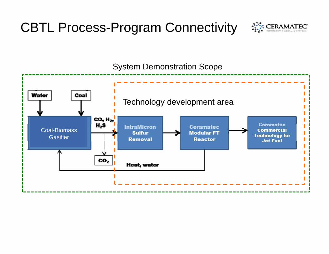
CBTL Process-Program Connectivity
Coal-BiomassGasifier
Technology development area
System Demonstration Scope
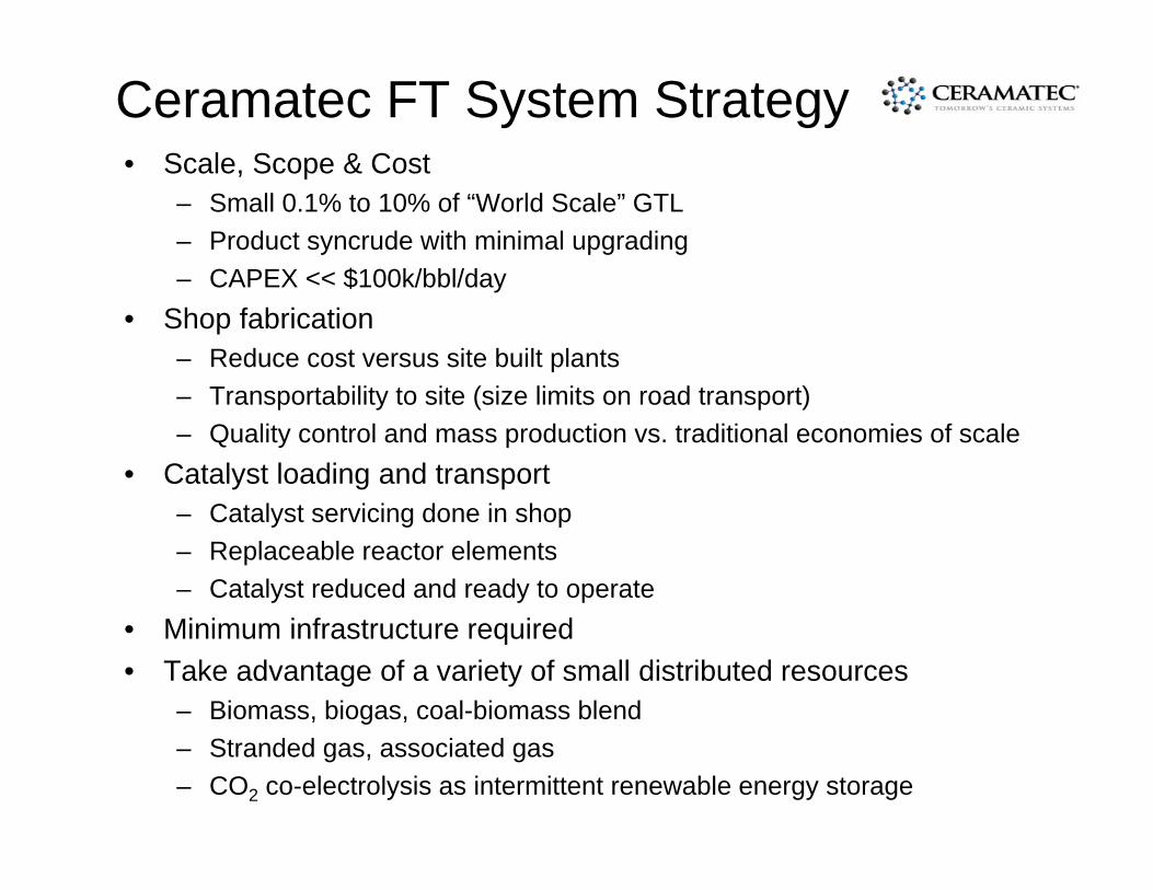
Ceramatec FT System Strategy• Scale, Scope & Cost
– Small 0.1% to 10% of “World Scale” GTL– Product syncrude with minimal upgrading– CAPEX << $100k/bbl/day
• Shop fabrication – Reduce cost versus site built plants– Transportability to site (size limits on road transport)– Quality control and mass production vs. traditional economies of scale
• Catalyst loading and transport– Catalyst servicing done in shop– Replaceable reactor elements– Catalyst reduced and ready to operate
• Minimum infrastructure required• Take advantage of a variety of small distributed resources
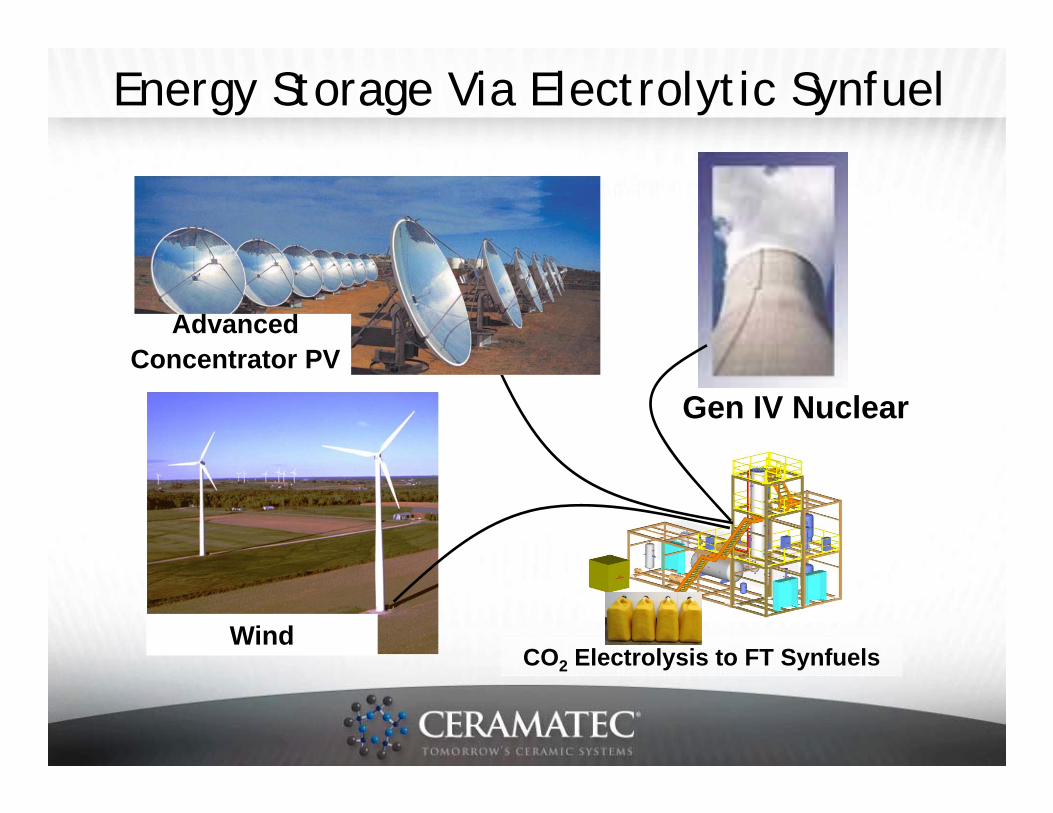
– Biomass, biogas, coal-biomass blend– Stranded gas, associated gas– CO2 co-electrolysis as intermittent renewable energy storage
1. Produce products that include a commercially-viable quantity of jet fuel (e.g., Jet-A or JP-8 MIL-DTL-83133);
2. Make significant progress toward compliance with Section 526 of the Energy Independence and Security Act of 2007 (EISA 2007 §526) lifecycle greenhouse gas (GHG) emissions requirements; and,
3. Make significant progress toward being cost-competitive with conventional petroleum-based jet fuel.
4. A “commercially-viable quantity” would be the minimum amount of fuel on a regular basis that would be purchased at a cost-competitive price by either the Defense Logistics Agency (DLA Energy) or a commercial aviation fuel-buying agency. For the purposes of this FOA, Applicants should have in mind target plants that would be able to deliver a minimum of thousands of gallons of jet fuel per single customer purchase.
• The Ceramatec lead team is proceeding with demonstration of nominal 2 bbl/day FT pilot plant, producing a nominal 1 bbl/day in the Jet-A/JP-8 fraction. This will produce over 1,000 gallons of jet fuel per month, and be the basis of a 100 bbl/day module producing over 2,000 gallons of jet fuel per day.
Project Goals and Objectives
1. Produce products that include a commercially-viable quantity of jet fuel (e.g., Jet-A or JP-8 MIL-DTL-83133);
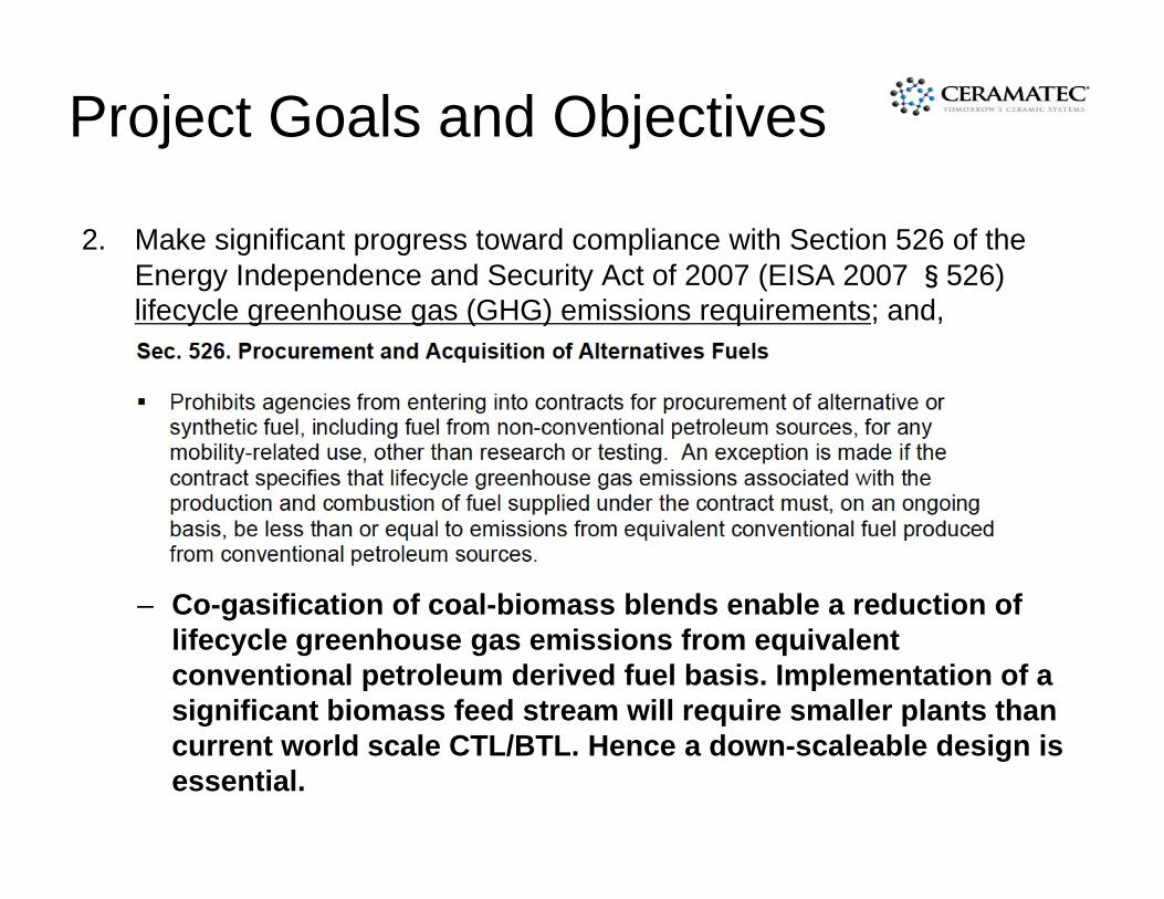
2. Make significant progress toward compliance with Section 526 of the Energy Independence and Security Act of 2007 (EISA 2007 §526) lifecycle greenhouse gas (GHG) emissions requirements; and,
– Co-gasification of coal-biomass blends enable a reduction of lifecycle greenhouse gas emissions from equivalent conventional petroleum derived fuel basis. Implementation of a significant biomass feed stream will require smaller plants than current world scale CTL/BTL. Hence a down-scaleable design is essential.
Project Goals and Objectives
1. Produce products that include a commercially-viable quantity of jet fuel (e.g., Jet-A or JP-8 MIL-DTL-83133);2. Make significant progress toward compliance with Section 526 of the Energy Independence and Security Act of 2007 (EISA 2007 §526) lifecycle greenhouse gas (GHG) emissions requirements; and,
3. Make significant progress toward being cost-competitive with conventional petroleum-based jet fuel.
• Due to the reduced part count and complexity of Ceramatec’s 4” modular reactor design, fabrication and maintenance (catalyst service) cost are significantly reduced compared to conventional small tube fixed-bed FT reactors, or the advanced micro-channel reactors.
• A simplified process flow-sheet made possible by advanced, wax free catalyst requires only modest upgrading or refining to produce a significant jet fuel fraction. Elimination of the wax hydrocracker and hydrogen plant is a major simplification and cost savings in construction and operation.
• A mass-produced, modular, road transportable plant design can achieve world scale economies of scale in small plants that can be sized and reconfigured to match the biomass resource.
Project Goals and Objectives
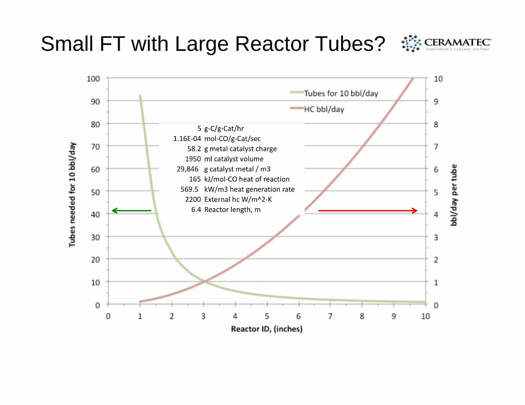
Small FT with Large Reactor Tubes?
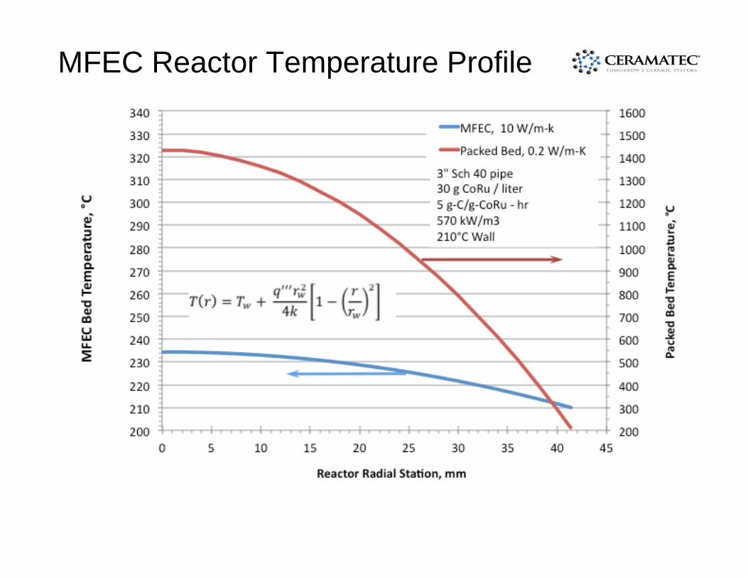
MFEC Reactor Temperature Profile
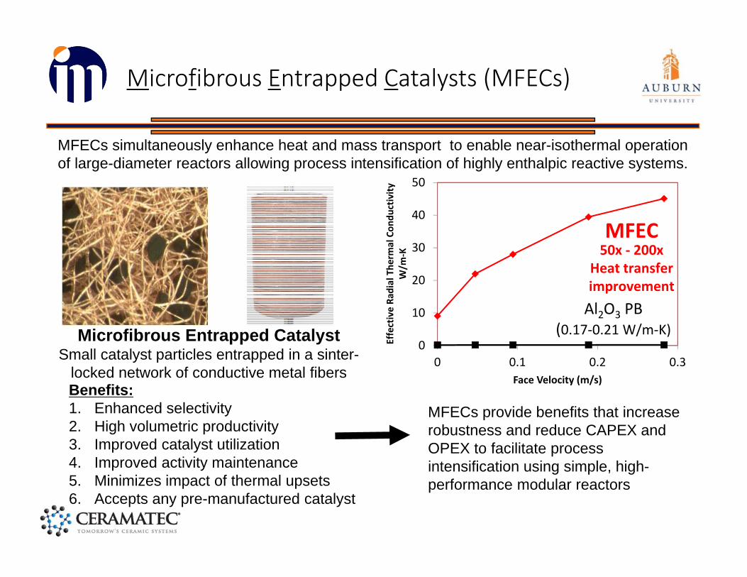
Microfibrous Entrapped Catalysts (MFECs)
Microfibrous Entrapped CatalystSmall catalyst particles entrapped in a sinter-
locked network of conductive metal fibers
MFECs simultaneously enhance heat and mass transport to enable near-isothermal operation of large-diameter reactors allowing process intensification of highly enthalpic reactive systems.
Benefits:1. Enhanced selectivity2. High volumetric productivity3. Improved catalyst utilization4. Improved activity maintenance5. Minimizes impact of thermal upsets6. Accepts any pre-manufactured catalyst
0
10
20
30
40
50
0 0.1 0.2 0.3
Effective Ra
dial The
rmal Con
ductivity
W/m
‐K
Face Velocity (m/s)
MFEC
Al2O3 PB(0.17‐0.21 W/m‐K)
50x ‐ 200xHeat transfer improvement
MFECs provide benefits that increase robustness and reduce CAPEX and OPEX to facilitate process intensification using simple, high-performance modular reactors
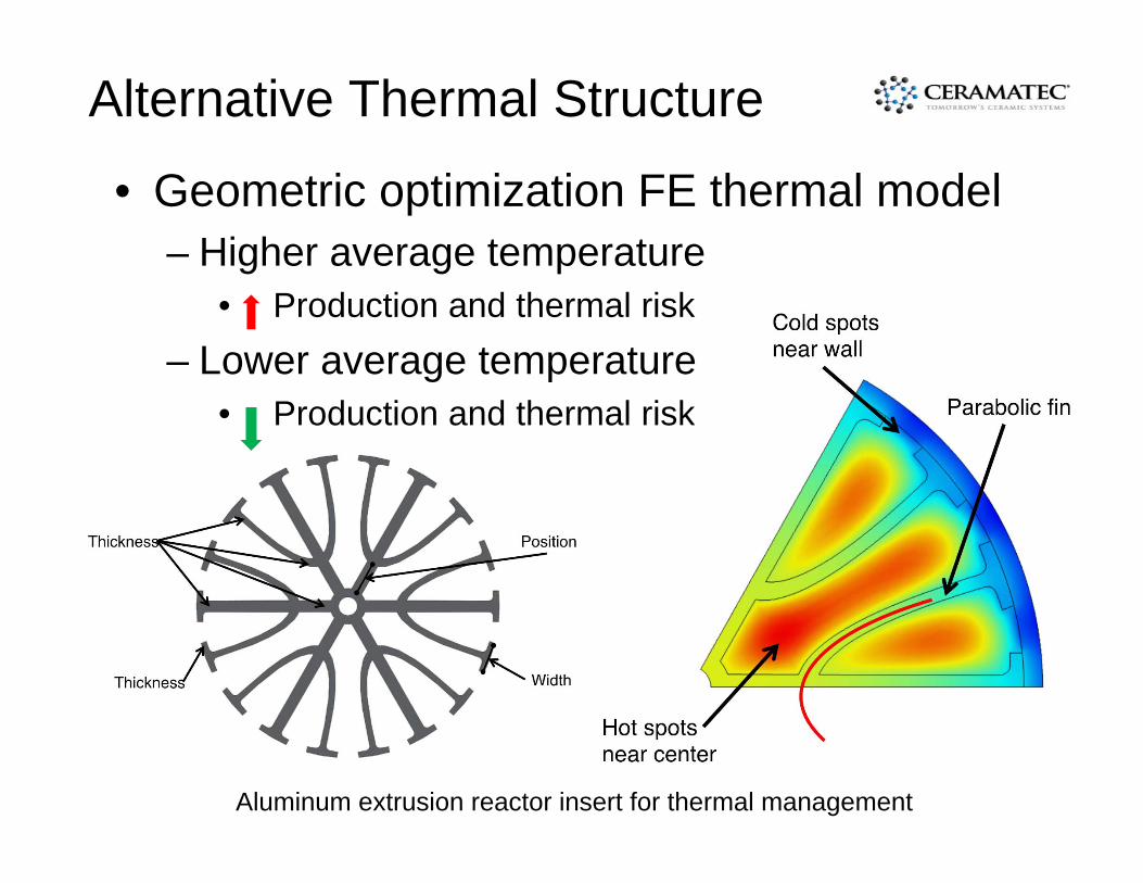
Alternative Thermal Structure
• Geometric optimization FE thermal model– Higher average temperature
• Production and thermal risk– Lower average temperature
• Production and thermal risk
Aluminum extrusion reactor insert for thermal management
IntraMicron Desulfurization Technology Suite (IM‐DTS)
IntraMicron’s Scalable Desulfurization Technology Suite is a synergistic combination of an oxidative sulfur removal (OSR) Catalyst, a desulfurization sorbent (regenerable or disposable), and a bed life sensor that enables efficient sulfur removal from distributed energy resources.
• OSR converts majority of H2S to elemental sulfur without significant SO2 production• BLS optimizes adsorbent utilization to minimize waste• Process easily accommodates varying sulfur levels and outlet thresholds• Up to 75% cost reduction compared to current state of the art technologies
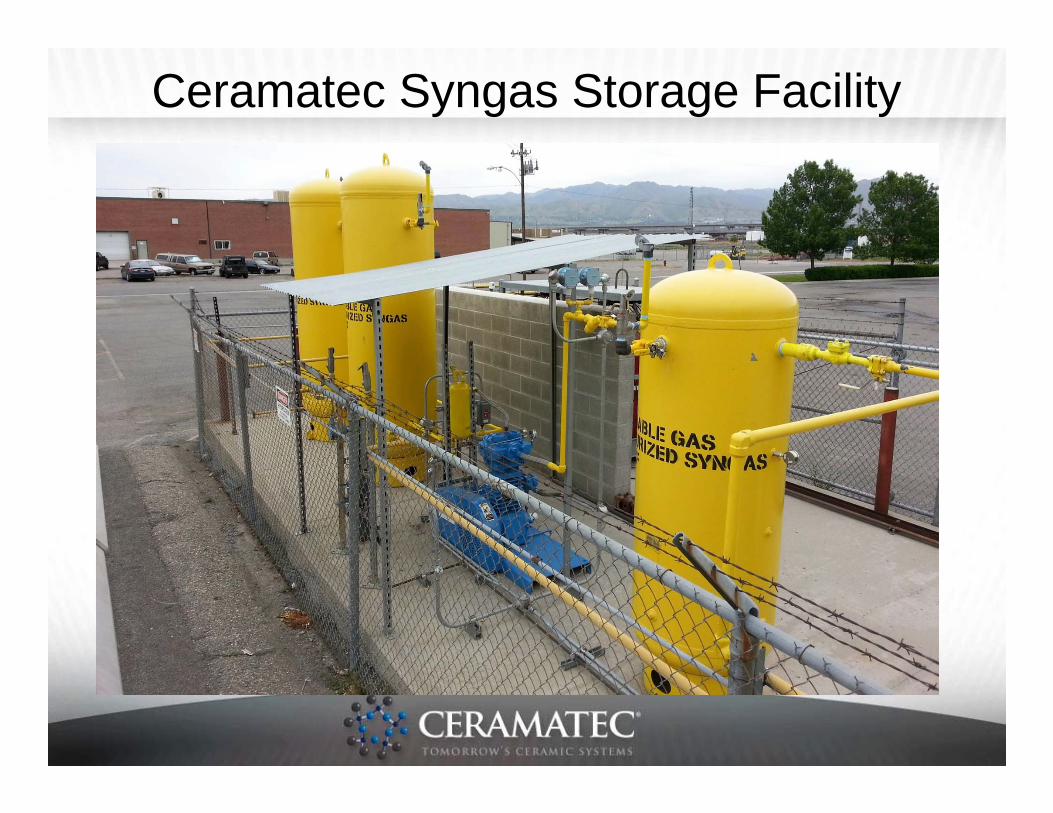
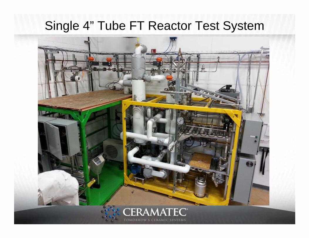
Ceramatec 4” FT Pre-Pilot Facility
• Plasma reformer• Syngas
compression• Syngas drying• Syngas storage• Modular reactor• 4” dia advanced FT
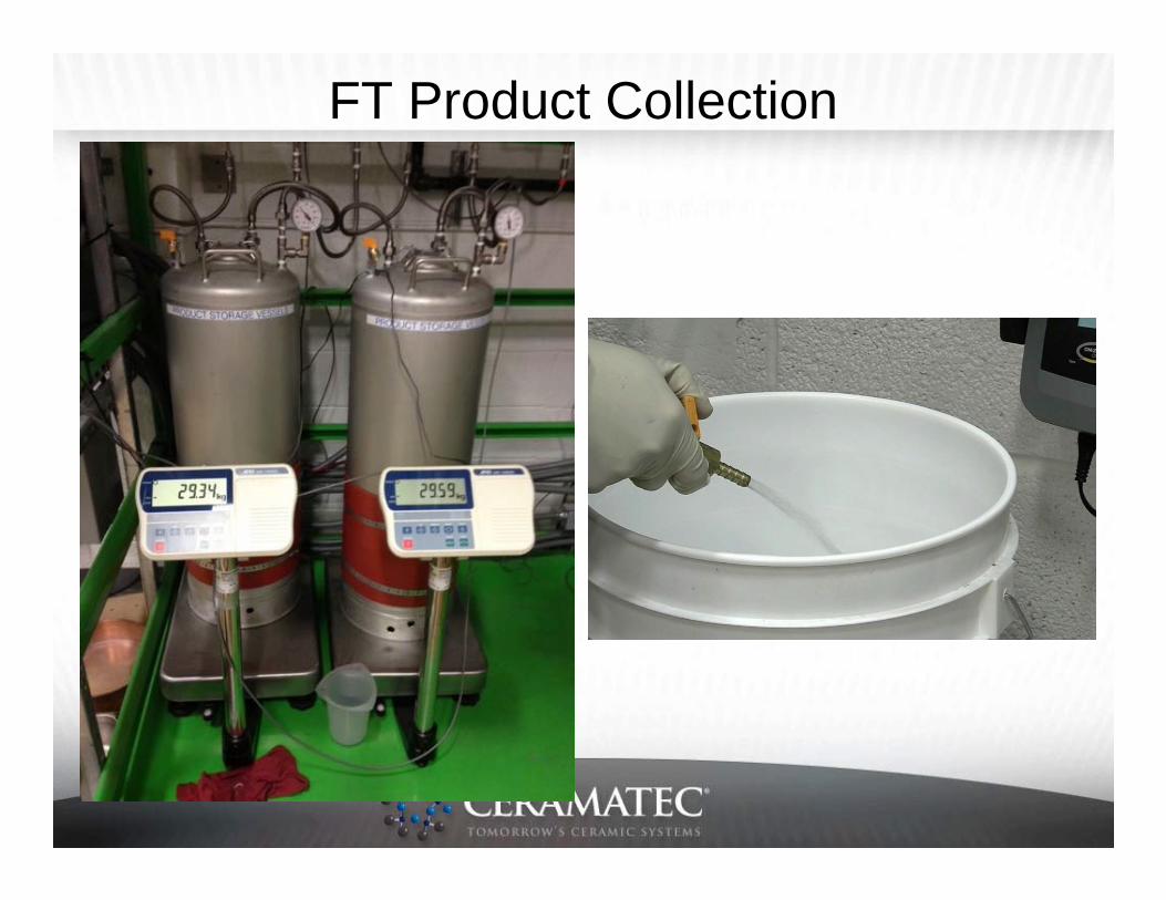
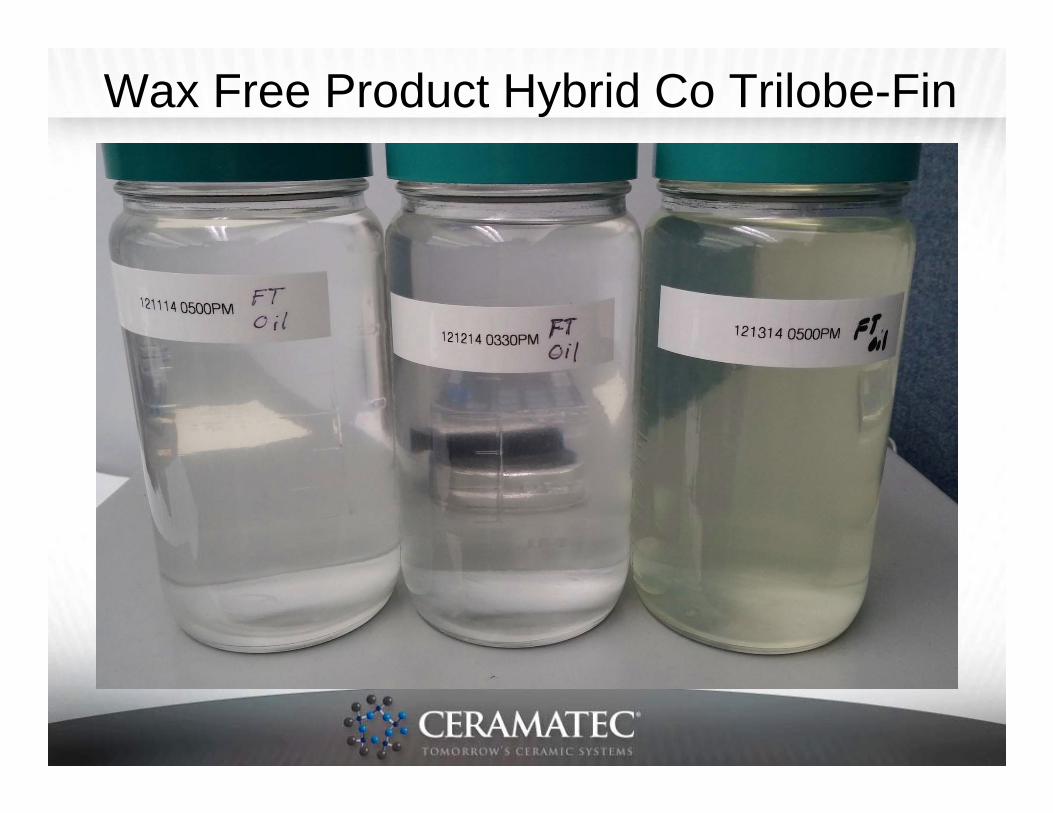
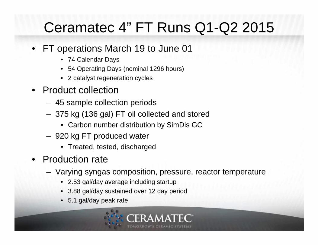
• Product collection– 45 sample collection periods– 375 kg (136 gal) FT oil collected and stored
• Carbon number distribution by SimDis GC– 920 kg FT produced water
• Treated, tested, discharged
• Production rate– Varying syngas composition, pressure, reactor temperature
• 2.53 gal/day average including startup• 3.88 gal/day sustained over 12 day period• 5.1 gal/day peak rate
Selectivity & Productivity Extrudate-Fin• 23 Dec 2014
– 1.25 kg hybrid Co trilobe– 240°C reactor– 20 bar exit– 3.22 SCFM syngas
• 35% N2, 40% H2, 19% CO
– 8 SCFM recycle– 92% H2 conversion– 86% CO conversion– 23.3% CH4 selectivity– 3.4% CO2 selectivity– 0.197 gC5+/g-cat/hr
• 16 Oct 2014– 1.25 kg hybrid Co trilobe– 250°C reactor– 20 bar exit– 4.59 SCFM syngas
• 52% N2, 29% H2, 14% CO
– 10 SCFM recycle– 79% H2 conversion– 71% CO conversion– 32.5% CH4 selectivity– 2.6% CO2 selectivity– 0.091 gC5+/g-cat/hr
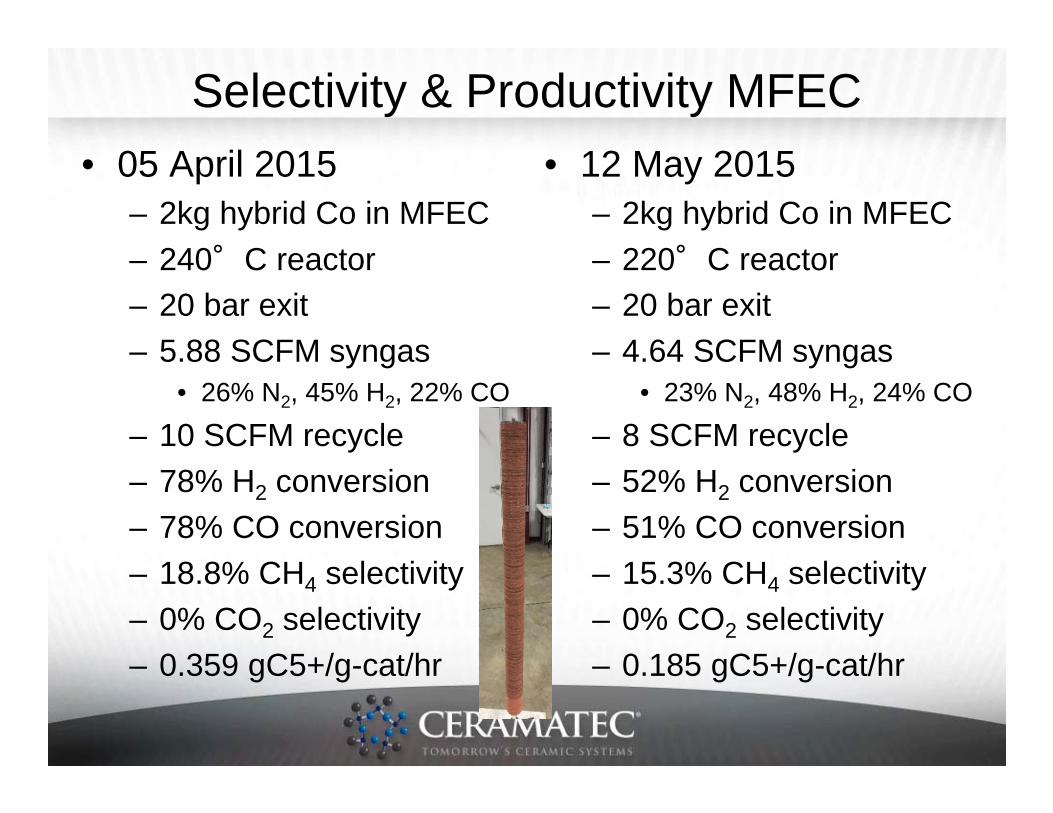
Selectivity & Productivity MFEC• 05 April 2015
– 2kg hybrid Co in MFEC– 240°C reactor– 20 bar exit– 5.88 SCFM syngas
• 26% N2, 45% H2, 22% CO
– 10 SCFM recycle– 78% H2 conversion– 78% CO conversion– 18.8% CH4 selectivity– 0% CO2 selectivity– 0.359 gC5+/g-cat/hr
• 12 May 2015– 2kg hybrid Co in MFEC– 220°C reactor– 20 bar exit– 4.64 SCFM syngas
• 23% N2, 48% H2, 24% CO
– 8 SCFM recycle– 52% H2 conversion– 51% CO conversion– 15.3% CH4 selectivity– 0% CO2 selectivity– 0.185 gC5+/g-cat/hr
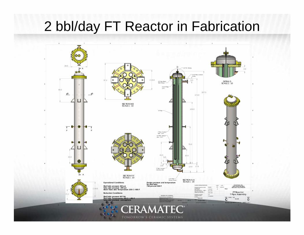
2 bbl/day FT Reactor in Fabrication
30.0
48.0
A
A
BB
FF
30.5
21.1
34.0
174.0
44.0
76.0
14.8
207.0
30.0
126.0
17.8 3.8
6.0
5.0
D
SECTION A-ASCALE 1 : 20
1-1/2" PipeProduct Outlet
2" Pipe, Coolantdraining outlet
1" Pipe, Coolantinlet. 1 of 6
1/2" Pipe, Syngasinlet. 1 of 3
2-1/2" Pipe, CoolantOutlet.
1/4" T.C. Tubing
3-1/2" FT Pipe1 of 7
20" Pipe
20" Tube SheetBlind Flange
37.2 20.0
SECTION B-BSCALE 1 : 10
4.6
DETAIL DSCALE 1 : 10
SECTION F-FSCALE 1 : 10
Operational Conditions:
Shell side pressure 450 psiTube side pressure 290 psiShell / Tube side Temperature 235 C / 455 F
Reduction Conditions:
Shell side pressure 657 PsiShell side Temperature 255 C / 491 FTube side pressure atmospheric
Design pressure and temperaturefor shell side:738 psi and 509 F
D
C
B
A
B
C
D
12345678
8 7 6 5 4 3 2 1
E
F
E
F
01-00
SHEET 1 OF 1
FT Reactor7 Pipe Assembly
6/30/15
JH
0
UNLESS OTHERWISE SPECIFIED:
SCALE: 1:50 WEIGHT:
REVDWG. NO.
CSIZE
TITLE:
NAME DATE
COMMENTS:
Q.A.
MFG APPR.
ENG APPR.
CHECKED
DRAWN
As specified
Material FINISH
MATERIAL
INTERPRET GEOMETRICTOLERANCING PER:
DIMENSIONS ARE IN INCHESTOLERANCES:FRACTIONALANGULAR: MACH BEND TWO PLACE DECIMAL THREE PLACE DECIMAL
APPLICATION
USED ONNEXT ASSY
PROPRIETARY AND CONFIDENTIAL
THE INFORMATION CONTAINED IN THISDRAWING IS THE SOLE PROPERTY OFCERAMATEC INC. ANY REPRODUCTION IN PART OR AS A WHOLEWITHOUT THE WRITTEN PERMISSION OFCERAMATEC INC IS PROHIBITED.
A
DO NOT SCALE DRAWING
Ceramatec Inc.2425 South 900 West
Salt Lake City UT 84119AG
5,250 lbs
Ceramatec 10 bbl/day Pilot Plant Designed & Priced
• Three skids plus container and air compressor– Skid 1: 12’ x 12’ x 36’– Skid 2: 12’ x 12’ x 32’– Skid 3: 12’ x 12’ x 24’
FT Reactor
Plasma reformer
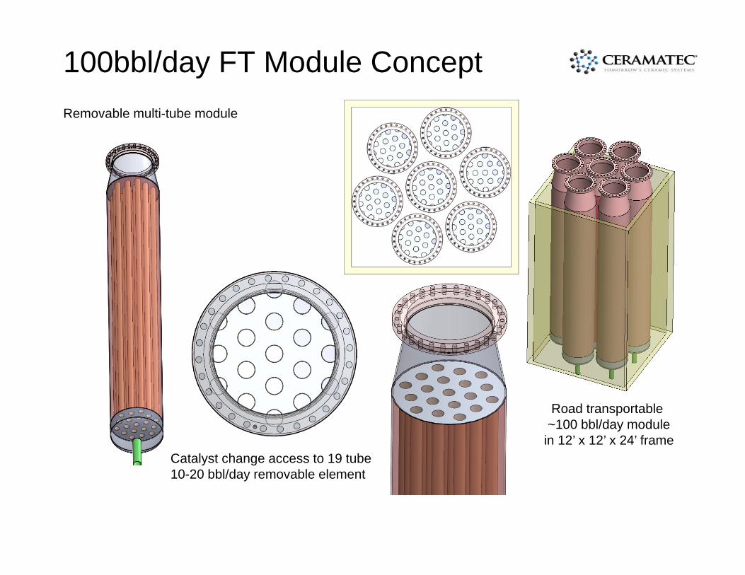
100bbl/day FT Module ConceptRemovable multi-tube module
Catalyst change access to 19 tube10-20 bbl/day removable element
Road transportable ~100 bbl/day module
in 12’ x 12’ x 24’ frame
Commercialization Prospects
• Ceramatec 4” FT reactor demonstrated• Next step, 4” multi-tube reactor
– Initial testing on plasma reformed natural gas– Coal gas testing with gasifier partner