NASA Contractor Report 18529 1 / .ri / , ,,'/ I- C , /" Green's Functions for Dislocations in Bonded Strips and Related Crack Problems R. Ballarini and H.A. Luo Case Western Reserve University Cleveland, Ohio September 1990 Prepared for Lewis Research Center Under Grant NAG3-856 National Aeronautics and Space Administration __ - (YATA-CB-ld5291) GREFN'S f'UNCTTONS FOR 1L9 0- 2 8 -9 7 d dTSLOCATIDNS IN bOhDED STPI:P5 ANU RELATC'C CRACri PRd9LFMS Final Report: (Case Western Aessrve Univ,) 47 n cscc 7OY Uncl ds 63/39 0305452 https://ntrs.nasa.gov/search.jsp?R=19900019562 2018-06-01T12:50:09+00:00Z
Transcript
NASA Contractor Report 18529 1
/
.ri / , ,,'/ I-
C , /"
Green's Functions for Dislocations in Bonded Strips and Related Crack Problems
R. Ballarini and H.A. Luo Case Western Reserve University Cleveland, Ohio
September 1990
Prepared for Lewis Research Center Under Grant NAG3-856
National Aeronautics and Space Administration __ -
( Y A T A - C B - l d 5 2 9 1 ) GREFN'S f'UNCTTONS FOR 1L 9 0- 2 8 -9 7 d d T S L O C A T I D N S I N bOhDED S T P I : P 5 ANU RELATC'C C R A C r i P R d 9 L F M S F i n a l Report: ( C a s e Western A e s s r v e U n i v , ) 47 n cscc 7 O Y Uncl d s
Green’s functions are derived fa the plane dsetoetatica problem of a dislocation in a bimerterial strip. Using theae: fundamental eaiutione M kemeia, varioua problane involving c r d a in a bimaterid strip are analyzed using singular integrd equations. For eachproblemamsidaed, etrese int;meityfactars amcalcnlated5cn eevdcombinationa of the patametan, which describe loading, ppxwtry aadnlatezial m i d
1 Introduction
The mechanical behavior of bimaterird interfaces in composite materials is currently a topic
of considerable interest to the applied mechanics community. Many analytical, numerical
and experimental inveatigationrr have been conducted recently to gain a better d & d -
ing of how these interfacts &ect bulk compoeite propertice such as strength, s t i h s s and
toughness. The mechanisms of cracking or debonding dong bimatchl interhces arc of
parthlar interest in brittle composites since it haa been established experimezltdly and
through minomechanical mod& thrrt certain desircd properties can only be schieved in
such materiab if the cracks which inifiate in the matrix arc deflected by the fibas dong the
fiber-matrix interface [l]. It is clurr that micromechanical d ~ ) wi l l continue to play an
important role in analyzing and designing brittle composites to ensure thb desired
1
seqaenct. Moreover, upeximental programs arc necessary to measure the fiacturt tough-
ness of the fiber-matrix intuface because the conditione required for the d d behavior
involve the relative toughness between the fiber and the interface.
Micromechasical mod& which involve relatively aimple geometrim such 88 cmcb in
a t e and s e m i - s i t e plane bo&- ~ S V C been handled acing distributed d i e l ~ ~ l r t i ~ m and
singular integral quatione [2]. For complicated h i t e geometries, on the other hand, the
bite element method haa gained popularity [3,4]. The eingalar integral equation method
hae two advantages. First, it leads to accurate rewlts for etrees intensity fsctom. Second,
once the Green’s functions arc derived and the quatiom
be performed by simply varying the dimcnsiodcse parameten, which describe the loading,
crack length and geometry. Unfortunately, if the geometry of the problem ia complicated,
the method is not feasible became it ie very difEdt to derive the kernels. The real advantage
of the h i t e element method ia ita ability to model complicated geometries. If proper care
is taken, the method dso produces accurate results. Pammetu studies, on the other hand,
are time consuming and relatively CILmbersome.
eet ap, panrmetu s t n b
Thia paper addmwca a class of problems which involve cracks in bonded Stripe. The
motivation of thia work uune from a desire to develop a computer program which could
be used to d d t e stress intensity factors and energy nleaee rates for bimaterid fracture
specimens being developed st C.W.ItU., and model the geometry of the eo-ded Santa
Barbara mixed-mode epedmcn shown in Figure la. The latter “T-crack” codiguration was
developed by Chamlambides et aL [3,4] at the Univexsity of Wornia at Santa Barbara to
measure the fracture resistance of bimaterial interhcm. To interpret experimental rcaulte
and to guide the dcsign of the spedmen, they developed a finite clement approach to char-
t& trends in st- intemity factors, energy releaee rates and center paint diaplaccmests
with specimen dimemiom, clastic propertics and crack length, Ae dtscasaed in [3,4], the
strees intensity factors and energy release rate for the crack growing along the interface
exhibit steady Btate behavior a8 a d t of the constant moment within the inner load-
ing points. The shortat crack for
all = 0.0938 (or c/Az = 0.3127). which d t a aim calculated in [3,4] is approximately
The malts showed that this crack length ia already
2
at steady state. One of the questitma left unanswered ie: haw long does the crack have
to grow along the interface before it reaches steady state? To answer this question the
problem is modeled in this paper using the singular integral equation technique. R~~dts
will be presented for relatively shoit crack lengths as d ad for the case a = 0, e hz
(Fig.lc, Fig.ld, F'ig.1~). It should bc noted that at the end of this work the authors learned
that Charalambides hae recently obtained results for both the transient region and for the
three-point loading configuration.
In the next section Green's functions are derived for edge dislocations in is bimatezial
drip. These fundamental solutions can be d in tarn to sct up the integral eqaatiOne
for all the configurations shown in F S p 1. It should be noted that this class of problems
has been analyzed by Ln [5] and Lu and Erdogan [e] using Fourier traneforms. In [5,6]
the problems were reduced to singdar integral equations without the use of dislocationa as
fundamental solutions. Dislocation densities, however, w a e dehed eventually to set up the
integral eqnations. In this paper the: dislocations arc introduced as fnndamentd solutions.
This will enable ne, in the htm, to solve problems which involve non-eymmetric loading
and/or inclined cracks. In the third section the dislocation solutione arc used to set up
the integral quatiom for several configurations and loadingu. The l ad section presents
numerical d t a and comparieone with udsting ~~lu t ions .
2 Fundamental Solutions and Loading Conditions
Assume that two dissimilar elastic stripe are bonded along the 2 axis. The upper layer
(3 > 0) ia labeled by "1" and the lower layer (g < 0) is labeled by 9". The Green's fanctions for an edge dielocation in the b ima tcd strip are derived by superposing the solutione for
(1) a dislocation neat the i n t h e of two bonded half-plaaes; and (2) a bimaterial strip
loaded with boundary t h o r n which cancel out t h e induced by problem (1).
The 80Iuticw to problem (1) is well known. The stmasea and displacements, which will
be denoted by wperscript '(l)", can be w c p r e a s e d conveniently in terms of Mwkhelishvili'a
3
complex potentiah M
in which the m M p t i (i = 1,2) denotes "in region in; Qp1 and 8 1 cormpond to the
potentials for the upper half p h e and @z and 9 2 correspond to the potentials for the lower
half plane. Moreover, z is the complex variable x + iy, the prime denotes differentiation
with respect to x , au overbar denotee conjugation, p is the shear modulus, and IC is d&ed
in twms of Poiwon's ratio Y as R = 3 - 4u for piane Strain, and R = (3 - v) / ( l + Y ) for
plane stress. The complex potentiah for a dislocation located at = zo + igo azc given by
171
with
4
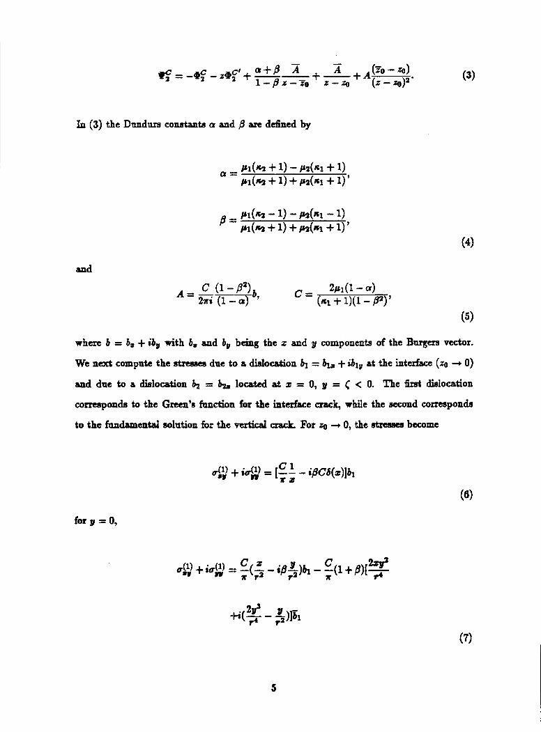
In (3) the Dundm conatants Q and. @ are defined by
and
w h m b = b, + ib, with b, and b, bcing the z and 0 components of the Burgers vector.
We next compute the gtresees due tco a dislocation b1 = + ibl , at the interface (zo + 0)
and due to a dielocation locsted at x = 0, y = C < 0. The Grat &location
corrtsponda to the Grten’e fandioni for the interface crack, while the second correspondis
to the fnndamtntd solution for the vtrtical crack For
=
+ 0, the stresses become
for 9 = 0,
5
I for y > 0, and
with
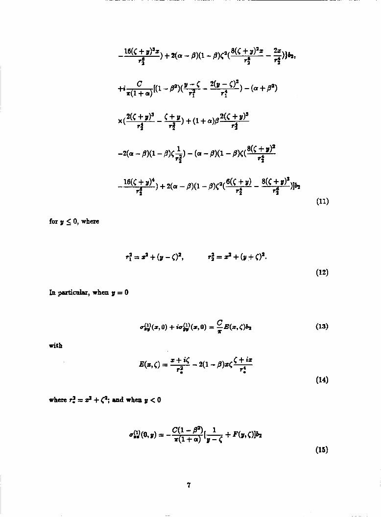
for y 2 0,
6
for y 0, where
with
when rz = 9 +e snd when y < 0
7
The solution to problem (2) is obtained by wing Fourier txansformation techniqaea.
Without loa of generality, coneider a binaterid drip Ioaded with surface tractionr, which
ill^ symmetric about the y-&. The hnricr transform of dieplacrmurt ia ZM follows:
The general solutions for Cri and K are [9]:
with the unknown cafiieimts detamincd by continuiw id boaadsry ~onditiona along the
I interhce:
8
9
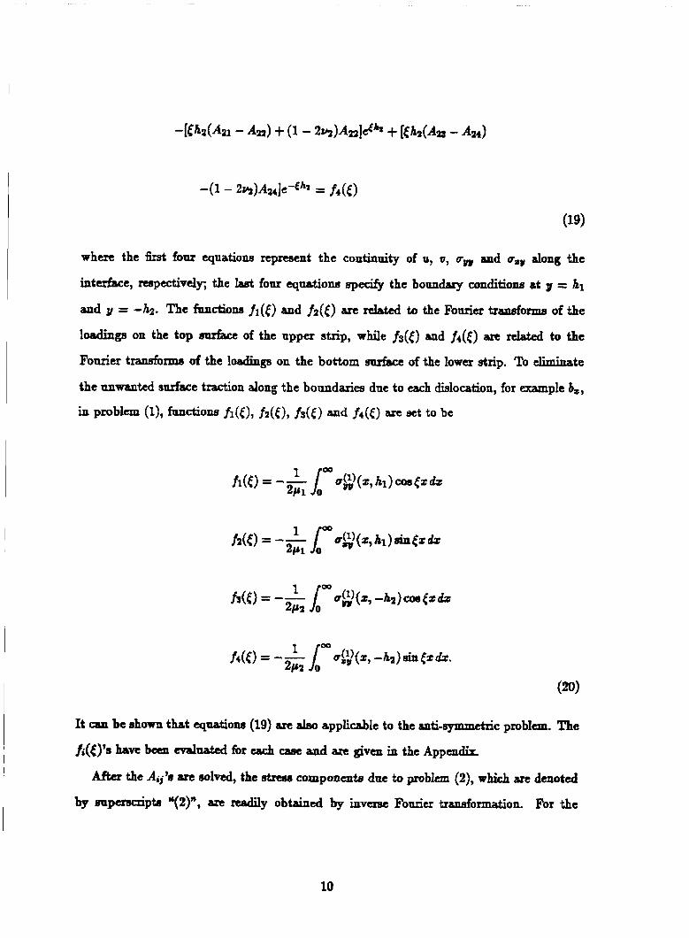
where the first four equationa represent the continuity of u, u, rOr and uIll along the
interface, respdvdfi the four equations ~ p e c i f y the boundary conditions 8t y = h1
and y = 4 2 . The functions !I([) and ti(<) are nlated to the Fourier transforma of the
loadinge on the top Blllfact of the upper strip, while fs(() and f&) are related to the
Fourier transfoxms of the loadings on the bottom surhcc ofthe lower strip. To eliminate
the unwanted anrface traction along the boundaries due to each dislocation, for example b,,
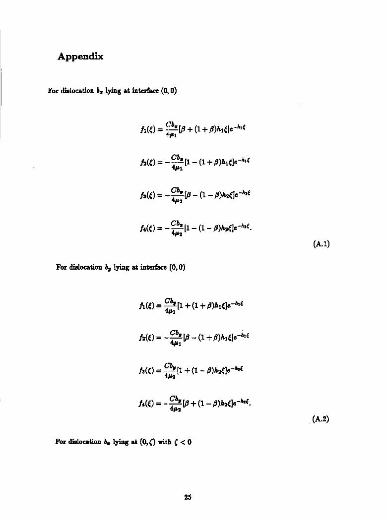
in P m b l a (11, fanctionfl fl(€), fz(€), fs(€> a d f4(€) are =t to be
It can be shown that equations (19) am alno applicable to the anti-symmctric problem. The
fi({)’e ~ W C b a n d~&4 for each case and are given in the A p p ~ ~ d k
Afta the Aij’8 are e~lved, the stress ~ o m p o n e ~ t s due to problem (2) , which are denoted
by wpuuuipta “(Z)”, are readily obtained by inverse Fonrier transformation. For the
10
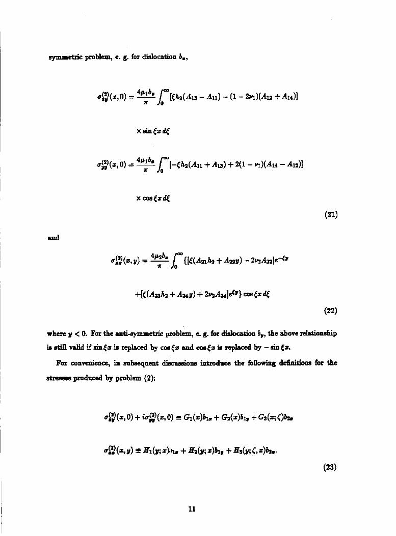
Symmetric problem, e. g. for dislocation b,,
when 3y < 0. For the anti-symmetric problem, e. g. for dielocation b,, the above &onehip
is stin valid if8intz is replaced by cos& and Cos~zis npbced by -sin@
convcmha, in wbeeqamt &&ns introduce the hllowing definitiom for the
stresses produced by problem (2):
11
We wieh to point out that the fnndamental roolntiona derived above can be used to solve
a large c l a ~ of problems. The prrrpoee of thia paper is to present the methodology. Thus
we wiU c o d e r only three topes of loadings. Thtsc include three and four point bending
(%.la), constant presenre dong the crack &ea, and a temperature change of the com-
p e t e atrip (Fig-ld). Conaider first a perfectly bonded himaterial beam subjected to four-
point bending. The stresses in the strip due to this loading condition caa be calculated using
composite beam theory if the strip is long enough. However, since we may be interested, in
the future, in analpaing relatively short beame, an eMcity solution is obtained in the mme
manner ~ E I for problem (2) of the dislocation solution. The applied loada are represented
by Dirac delta functione at the load points. That is cgl(z, hl) = -p[S(z - d ) + 6(2 + d)] /2
and uw(z, 4 2 ) = -p[6(z - e) + S(z + e)]/2. The functions f1, f2, f3 and f4 for thie
case are listed in the Appendix To evaluate the drama which arise h m this loading, it
may Beem natural to proceed in the same exact manner aa for the dielocation solutiom.
However, tremendous care muat be taken when evaluating the strema dong the interface
and along the line z = 0 due to this loading condition, became the integrals in the inverse
transformations converge very slowly. To improve the convergence the integrands are first
evaluated at = 00. The dominant portion of these limits, which correspond to half-space
adutiona, are wbtraded fiom and added to the integrands, and the added integrsla are
evaluated in c l o d form. The came procednn is also applied to the didocation when it
ia close to the bottom surface. For brevity the details of the procedure are not given here,
but can be recovwed in dmilnt analyses presented in [10,11].
Denote the stnssts produced by the four point bending M
respectidy, when p is the fonx per unit thickness. Them wil l be used in d o n 3 to set
12
up the integral equatiom.
The next loading condition CO&B of a d o r m change of temperatme A!l' of the
composite strip. The t h 4 atxearw in the strip arc d t x h c d wing beam theory [12].
In pasficalar, the strcssinlay~ 2 d00g theline z = 0 is givtn in t w of the thennd
expansion coefficiente q and a2 by
with
E @=-. 1 - 9
3 Integral Equations
several problem Consgtuatione arc d.epicted in Figare 1. The coordinate system is chosen
such that the z sxie liea dong the interface of the bimaterial etrip, and the g dong the
vertical crack 80 that layer 1 is at y :> 0 and layer 2 ia a& g < 0. The integral equations for
the four point bending problem ehmn in Fig.la arc sct up first. The str#lees along the lines
y = 0 snd 2 = 0 (3 I; 0) are given by the snmmatao . n of contributions &om problem (l),
problem (2) and the four point bend :load (24). Replacing the dialocationa by a didxibution
of dislocations enablca us to aatiefy the traction boundmy conditione along the d Thia
procedure leade to the following set of couplltd sirpgular integral equations:
13
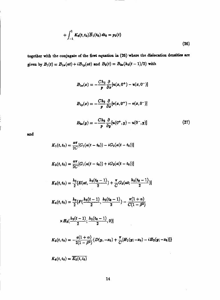
14
1 + a h,(t -- 1)) a(t) = -7rR(-- . 1-P 2
If the vertical crack is not prtsent, & is E& c q d zero and only the first equation of (26)
ia enforced. If the intcxha crack is not ptesent, on the other hand, the first of equations (26)
is not enforced and & is act qd to zero in the second ~ ~ t i 0 1 1 . For the edge crack nhc#w:
length c < hz, the dislocation density is instesd represented aa &(t) = &(c(t - 1)/2), and in the upreseion of the kernel 1Y.r given by (28) li2 needs to be replaced by c. Other
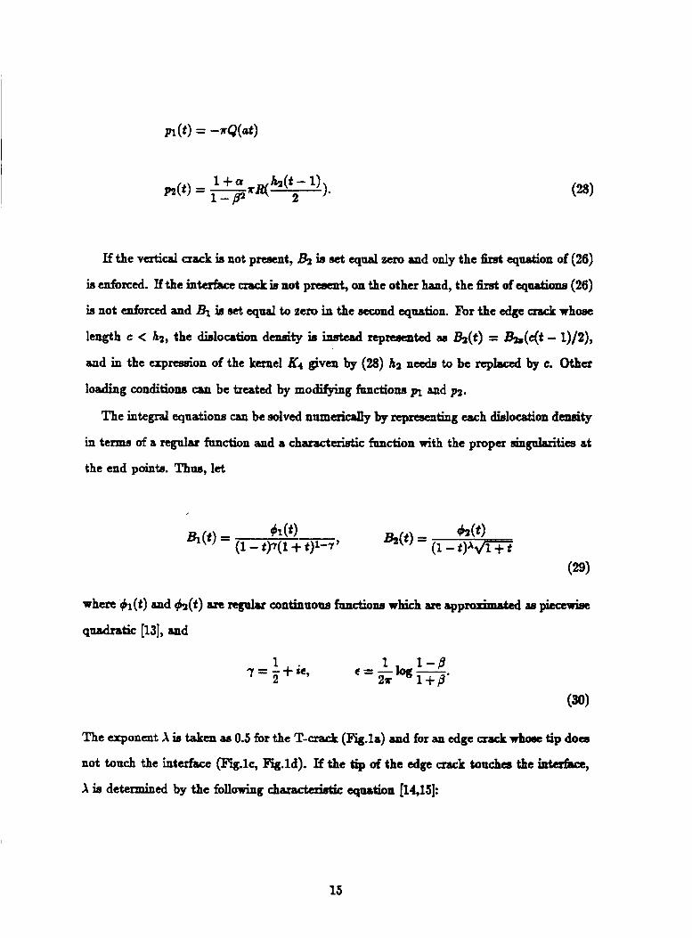
loading conditions can be treated by modifying fnnction~ pt and p3.
The integral equations can be solved namericsny by representing each dielodon density
in terms of a regular fanction and a cEwacteristic function with the proper singalarities at
the end pointa. Thus, let
when gl(t) and h(t) are regular continuous fanctione which arc approximated a p;eewii#
quadratic [13], and
The exponent X is taken a~ 0.5 for the ‘T-CsaEL (Figla) and for an edge crack wh- tip does
not touch the interface (Fig.lc, Figld). If the tip of the Oage crack touches the intafba,
X ia determined by the following characteristic equation [14,15]:
15
Using the method developed by Miller and K e u [13], integral equatione (26) can be reduced
to a set of algebraic equations.
The additional conditione to be ~atigficd are aa follows. For the T-crack
Quation (32) is the clogan condition for the horbonta crack, (33) repneenb the condition
that the etnse singnllvities at the tip of the vertical notch are lese than squan root, and (34)
implies the blnntnese at 2 = 0. Ae wi l l be diecoaeed in the next d o n , the represeatation
of the dialocation dcnrrity for the T-crack is not rigorous. However, the error introduced is
acceptable for the dgnra t ions considered in this paper.
For a single interface crack
and for a single edge aack
h(4) = 0
16
4 Numerical Results and Stress Intensity Factor Analysis
The stnse intensity fktor K of t h t c interface crack (Fig.lb) and the T d &.la) are
defined by [16]
It ~ k n be shown that in tenns of $iI(t), which is determined by equation (26) with (28) and
(B), this complex strtsa intensity fibctor can be e x p d
(39)
for the four paint bending load. h i : an edge crack whoee tip does not touch the interface
for the four point bending. For (UL edge crack whoee tip touches the intaface
17
I and
(43)
For the other loading carws, the factor p / h in (39) (41) aad (43) is replaced correspondingly.
The energy nleaee rate of the interface crack^ in the considered plane drain problems is
given by [17]
In order to check the lengthy algebra and the nnmexid scheme, two codgarations
which have prcviody been analymcd are considered first: a p d crackbetween
two bonded dissimilar layers and a p d e d vertical edge crack in the bottom hycr
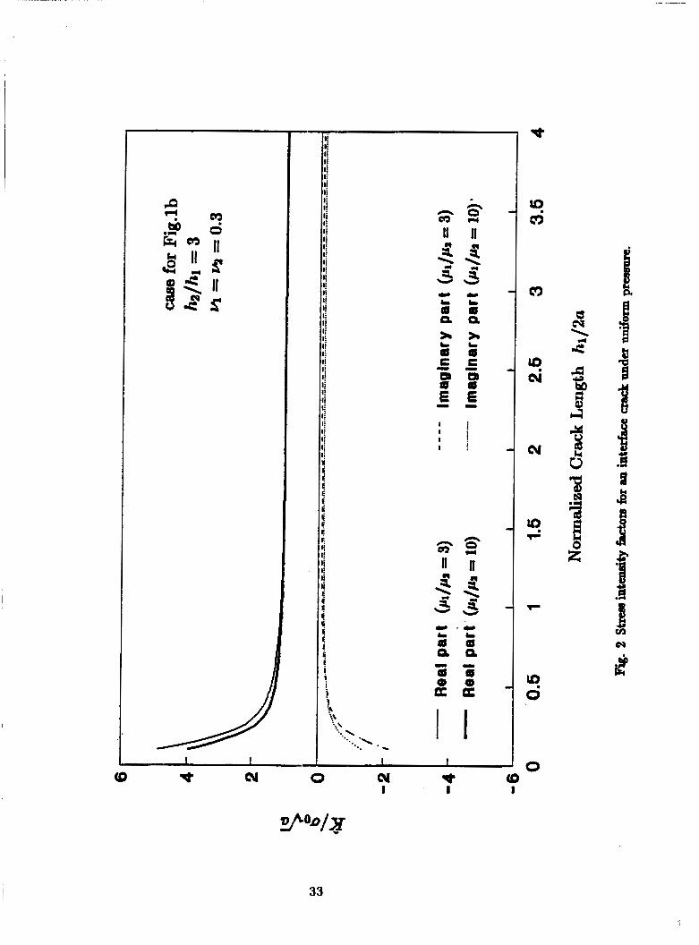
of a composite beam. Fig.2 ahom the dimenaionler#, stress in tens it^ fslctors K/uofi =
lk,-[(u - ~ > ' - 7 ( a + z)7(um + iusv)] /u~u vef911110.1 < h& 5 4 for the interface crack
with hz/R1 = 3, y = y = 0.3, p1/p2 = 3 and pl/p2 = 10, respectively. The results are
plotted in terrrm of this de6nition of stress intensity fador for comparison with nference
[18]. For h l / k > 0.5 the d t a agree with those presented in [la] (no results were given
there for h1/2a < 0.5). Ae expected, when the crack becomes shorter, the strars i n t d t y
factor convugca to 1 + 2ir which is the solution for an intcrhce crack between two bonded
half-spaces.
I
I
For the edge crack problem a homogeneous beam and four ceramic aunpordte strips arc
c~neidertd They ~ve: drip 1 Ti/Alzos ~ t h 4 = 0.322, y = 0.207 d p z / p l = 4.129,
strip 2 Ni/MgO with y = 0.314, g = 0.175 a d p2/p1= 1.588, Strip 3 MgOW1 and Strip 4
AbOs/Ti [16]. Wg.3 and Fig.4 show the dimensionlees Btrese intensity factore as fanctione
of crack length and relative thickneaa of the layem for the four point bmding ease c o n s i d d
in [3,4] when d = 5h2, e = 8ih and I = 3ihz. The qaantitg a,, is the iudal stress at the
18
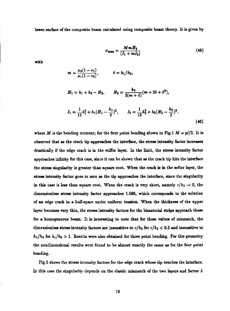
lower oarface of the composite beam calculated wing compoeite beam theory. It is given by
with
1 12 2 ’ 12 2
I2 = -g 1 + h2(& - - h2 12 . I1 = -h: + hl(& - -
(46)
where M is the bending moment; for the four point bending shown in Fig.1 M = p1/2. It is
observed that as the crack tip a p p n d a the interface, the stm intensity factor increases
drdcally if the edge crack is in the sMer layer. In the limit, the strese intensity fador
approaches infinity for this case, since it can be shown that as the crack tip hits the interface
the strese singularity is greater than aqnan root. Whm the crack is in the softer layer, the
stnse intemity factor go- to zero as the tip approaches the interface, eince the eingnlarits
in this case ia leas than square root. When the crack is very short, namely c/hz + 0, the
dimensionless stnse intensity factor approaches 1.586, which corresponds to the solution
of an edge crack in a half-space under d o r m tension. When the thickntes of the upper
layer becomes vuy thin, the Btrees intensity hctors for the b t e r i a l strips approach thost
for a homogeneous buun. It is intmading to note that for these valnea of mismatch, the
dimensionless stress inte.nsiQ fa,ctons arc insensitive to c/hz for c/h2 < 0.5 and insensitive to
hl/h2 for hl/ha > 1. Rewlta were a h obtained for three point bending. For thia geometry
the nondimensiod results were found to be dmost exactly the same 88 for the four point
bending.
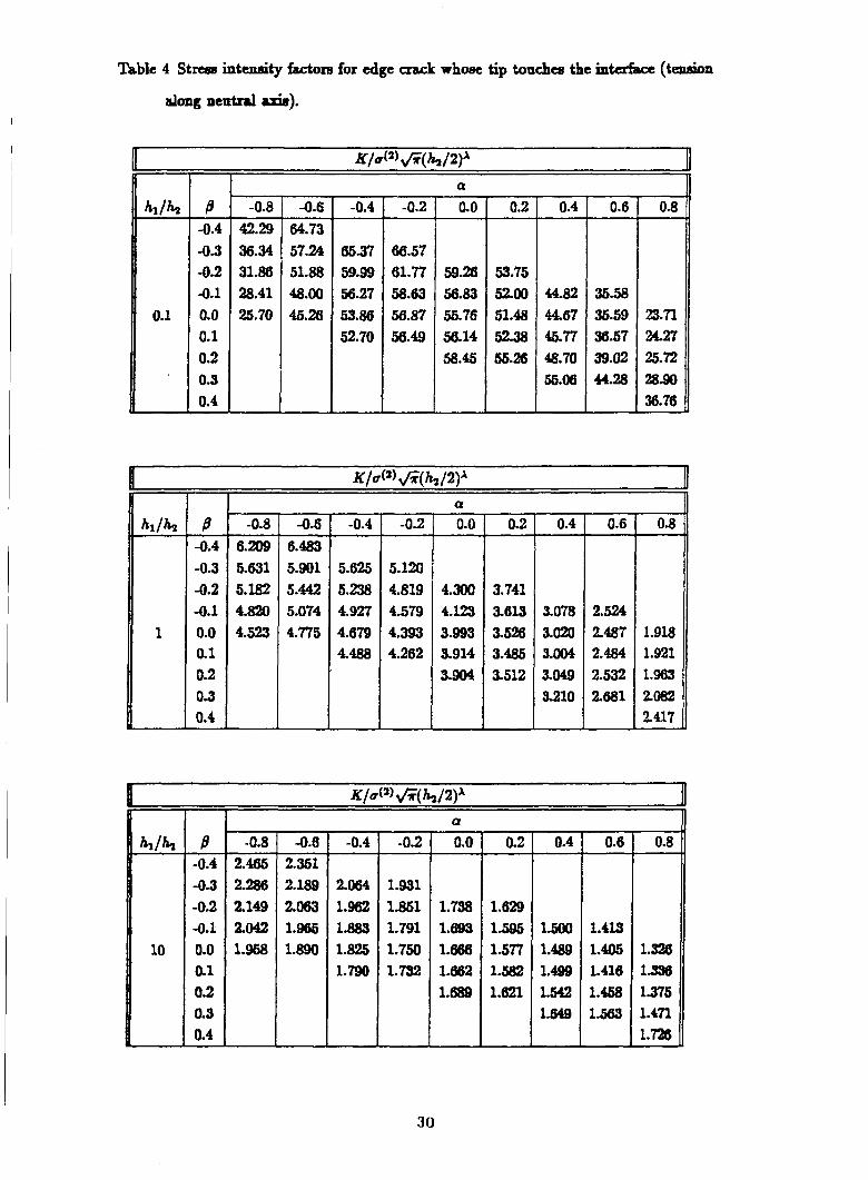
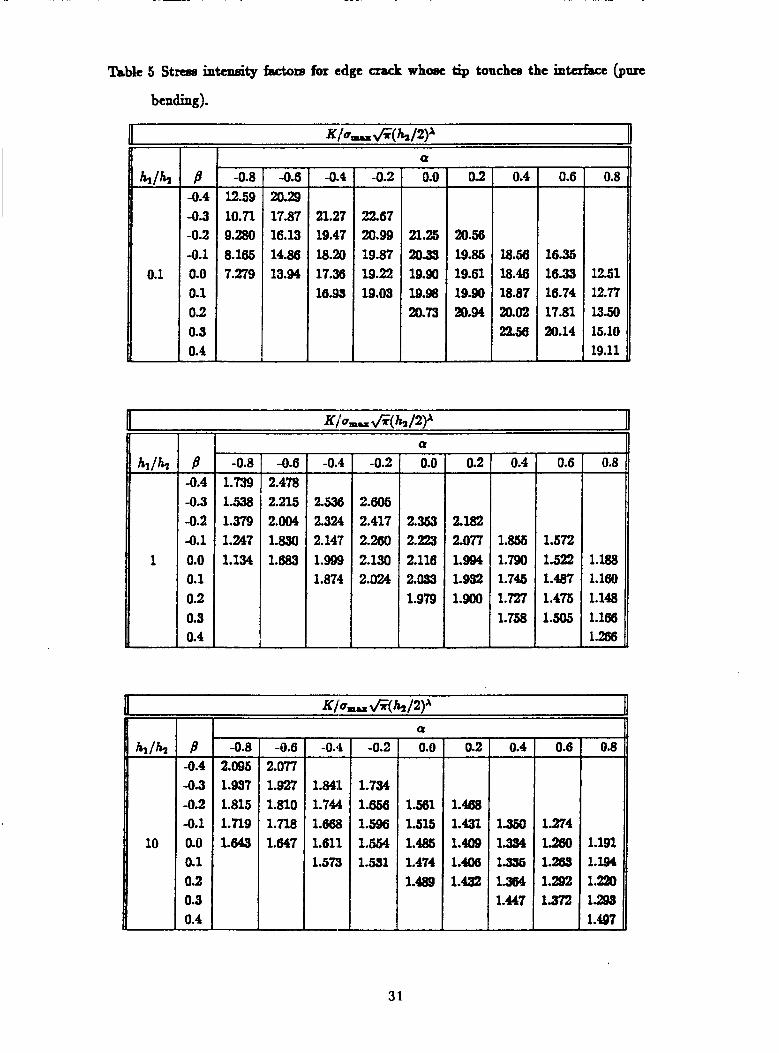
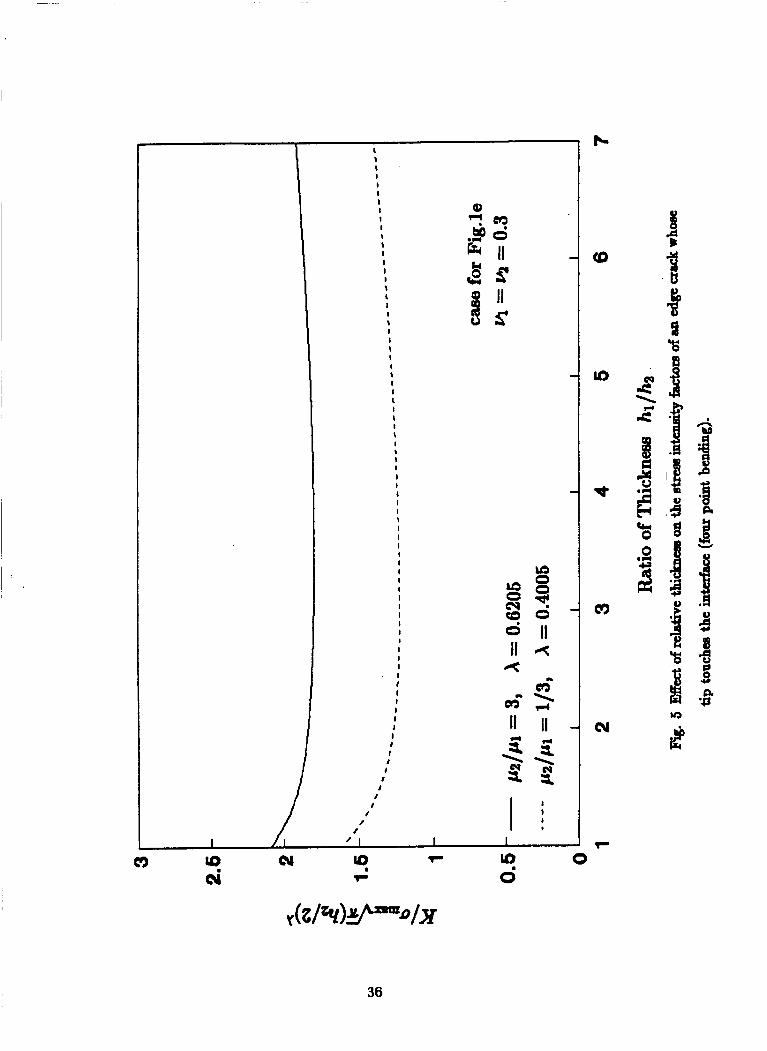
Fig.5 shows the stress intensity factors for the edge crack whose tip touches the interface.
In this caae the singularity depends on the elastic mismatch of the two layera and fador X
19
is calculated from (31). For the combination considexed hen y = y = 0.3, h l p l = 3 and
/ r ~ / p l = 1/3, and Bingnlarifies X = 0.6205 and X = 0.4005, nepectively. Notice that, since
the strarre singularities are Merent, it is mcsninglcua to directly compare the valuca of the
dimensionlaw strees intensity factore given in Fig.4 and Fig.5. It ehould be noted that t h e
results do not compare at all with those in [5,6].
Sappoec that a bimsterial beam is sabjected to a concentrated force p dong its neutral
axis at^ shown in Fig.lf where HI and H2 axe given by (46). The longitudid strcsa across
the lowa hycr ia
where C = pl(1- @)/[lr2(1- e)]. If the beam is subjected to the remote bending, based on the compoeite beasn theory, the s t m on the lowu layer is
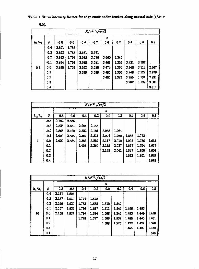
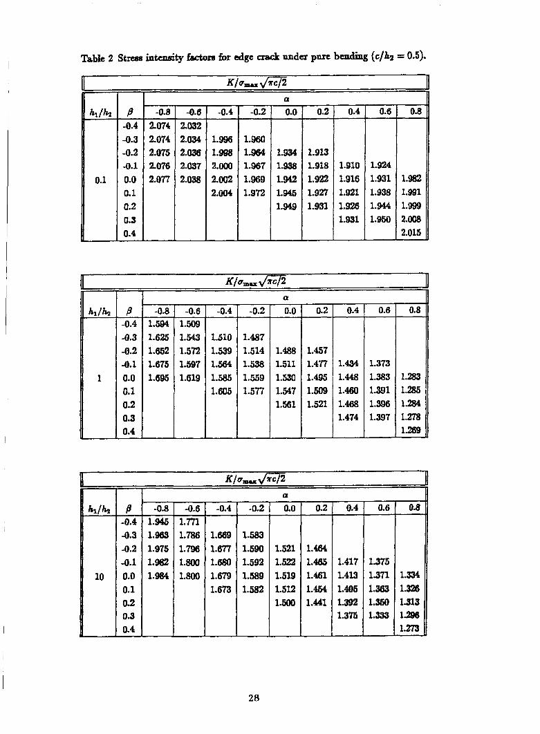
where umu and Hz are given in (45) and (46). Notice that two D d n r a patamdm a and
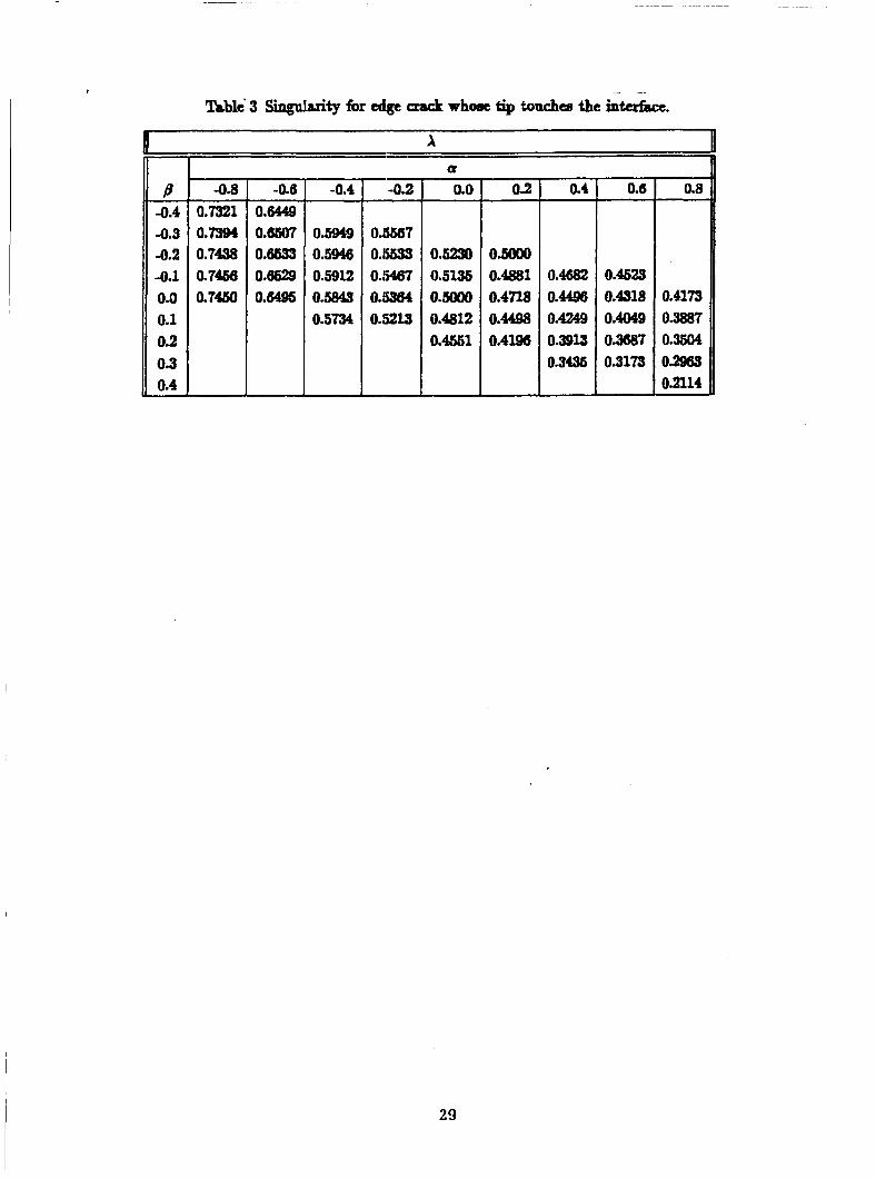
B ca,n ~JVCI the elastic moduli dependence of a twdimensioaal bimateria system [19]. In lbble 1 and lsb le 2 the streseintcnsityfactors arc given in terme of a and B for an edge
crmk with c/hz = 0.5 mdtr the &OVC two loading systeme. Table 3 shorn the Singalruity A
of the edge crack whoat tip touches the interface. The correeponding stnse intuwity fiLctora
am given for this class of edge craclm.
Fig.6 and Fig.? show the strese intensib factore of the edge cracks for the thermai losding
case. The sign of the Btreae intensity factor changes when the crack length ia approximately
equal to O.6h2 M a m d t of bending. If additional loads axe wperimposed, these results
wggerst that crack growth caa eithu be accelerated when (a2 - a1)AT < 0 or slowed down
when ( 0 2 - -)AT > 0 by the introduction of a temperstare change.
20
The last u a m p l e considas the 'T-cracL, which is r&rd to aa the Santa Barbara q~eci-
men, shown in Figart la when d = 5hz, e = 0ih.2 and 1 = 3fh.2. Results were calculated for
crack lengths which are ehortcr than thoee preeeplted in [3,4]. Fignn 8-14 show the dimen-
sionleee Btnse intenti@ factum KhLkhspfpl , energy release rates G and the phase angles,
defined (LB the w e n t of KAK, f a strips with y = e = 0.3 md pl/pz = 1, p ~ / h = 2.5,
p 1 / ~ = 5, pl/m = 10, nspectively. The nsnlts obtained in [3,4] for a / b > 0.5 am
superposed on the iigurcs. The agreement ie obeerved to be quite good. It i obmzvcd that
steady state begins at aack lengths equal to hg. ELeenlts for a/hz lese than 0.1 were not
calcplated because we believe that accurate mlutione cannot be obtained for these cases
using the pnsent formulation, since the integral equatione are coupled. To obtain actmate
results for d d u e of u/Az one would need to formalate the problem in term of a thgle
integral equation whoee kernel inchder, an analytic solution for the interaction of the two
cracks.
It should be mentioned that for crack lengths greater than 1.5Az convergent results were
not obtained a~ a d t of using a dietribution of &~OC&~ORS density which is continnone
at z = 0, y = 0. Because the vertical crack intersects the interface crack, the slope of
the horizontal crack is diecontinuom at (0,O). The numerical scheme implicitly assumes
that the dope there is m. We believe it is this error which lesde to poor rasulta for long
crack length, for which the elope at (0,O) is desaitely not aero. This problem is being
addressed by the authors at the pn-t time by introducing a dieeontinnow distribution of
ddOC&OM.
5 Conclusions
An analytical formulation has bean praeented which can be used to mlve a dase of plane
elaetoetatic problems involving cracked bimateria beamrr. M t a were calculakd only for a
few geometric c o d p a t i o n e and qmmetric loadinge. However, since the d y s i s relics on
fundamental ~olutiona for d ie10~at i0~ in bonded strips, other codgumtions mch (YI inclined
or curved cracb and/or non-symmdric loadings can be treated with minor modifications.
21
For the T-craEL, when the intcrhcc crack t relatively ehort, the rcsdte obtained wing the
singular integral equation approach compare very d with those obtained in [3,4] using
the finite element method. However, for such configarations, which involve diecontinuoua
didocation dmsities at the intersection of the two CraEllS, poor results wcre obtained for
nlatively long interface crach. Thia problem can be tnsttd by m o a the numerid
scheme to h a d e discontinuone didocation densities.
Acknowledgement
Fiaancial wpport waa provided by the D h Advanced &search Projects AgencJl
through the Univuaity B.march Initiative Pro~am of C.W.R.U. under ON& Contract
N-0013-SI<-0773 and by Lewis &eseatcb Center under Grat NAG3-856. The cornpub
tions were performed on a Cray which waa made available through a grant from the Ohio Supercomputer Center.
Fig. 1 Crack conf igar&iO~ for the bimaterial drip.
32
9
'rt
Lo - t i
I I I
33
c3
34
35
m
I t $ I I I I I I I 1 t I I I I 1 t I I t I I t I I 1 I I t I I I $ I t I I I I 8 I I 1 I I I I I I I I I I I I I I I I I I I I I I I
J I t I I t
I I
I I
I I
/
a?
Lo 0 0
36
W rl
a - 0
QD - 0
)c
- 0
- 0 <D
u) - 0
- d : 0
m - 0
cu - 0
T: 0 1
cu I 0
* I 0
aD 0
I
37
0 P I)
L
5 I I I I
a P .I
L
5
I
r
a I
L
G
I c3 0
cv 0
a rl
38
0
u) 0
* 0
0 0
cu 0
T: 0
39
I I I I I I s I I I I I I I I b * * I 1 I I * \ s I t I I t a I \ \ I I \ s \ \
I I
L L 6 0
6 I
t
I
a! 0
k 0
0
u) 0
* 0
m 0
N 0
7 0
0
n
2 II
aJ
40
I I1 1 I I I I I I 1 I 1 I I I I I I I \ \ I \ I \ t I \ I % t I 9 \ t \ \ I
cy I
Q 0
k 0
<9 0
Lo 0
d: 0
c3 0
cu 0
T 0
0
d
41
QD 0
k 0
0
Lo 0
* 0
m 0
cu 0
Y 0
0 0
42
0 0
43
0 cy I
s m II 3 i t
y?
II 3 '=.
cy
rt + n m
m a Y H
ti cc I I I
s II f > a
0 4
t
I I 1 I I I I I I 1 I I I I I I I I I I I I I I I I I I
I I 1 I II I I I I II I I I I I I I I I I I I I I I I I I I I I I I I 1 1 1 I I t 1 I 1 I I I I I I I I 1 I I 1 I I I 1 I 1 I I I I I I I I I I I I I I I I I I I 1 1 I I 1
0 L') I
0 * I
0 10 I
0 0 a I
44
ca
a
I
I
I
I
I
I I 1 I I I I I I I I I I I I I I I I I I I I I I I I I
I l
I I I I I I I I I I I I I I I I I I I I I I I 1 I I I I
! %i
3 2 t
r6 cu' II
4
m
5 8 c1
II 3 > 0
as 0
k 0
<s 0
v) 0
d: 0
c') 0
cu 0
Y 0
45
Dnnnrt 3ocu men tat ion Page
7. Author(s)
R. Ballarini and H.A. Luo
8. Performing Organization Report NO.
None
10. Work Unit No.
506-63-3 1
5. Report Date
Green’s Functions for Dislocations in Bonded Strips and Related Crack September 1990
NASA CR- 18529 I - 4. Title and Subtitle
9. Performing Organization Name and Address
Case Western Reserve University Department of Civil Engineering Cleveland, Ohio 44106
12. Sponsoring Agency Name and Address
National Aeronautics and Space Administration Lewis Research Center Cleveland, Ohio 44135-3191
Problems
11. Contract or Grant No.
NAG3-856
13. Type of Report and Period Covered Contractor Report Final
Green’s functions are derived for the plane elastostatics problem of a dislocation in a bimaterial strip. Using these fundamental solutions as kernels, various problems involving cracks in a bimaterial strip are analyzed using singular integral equations. For each problem considered, stress intensity factors are calculated for several combinations of the parameters which describe loading, geometry and material mismatch.
3, Security Classif. (of this report) 20. Security Classif. (of this page) 21. No. of pages
Unclassified Unclassified 48 22. Price’
A03
‘For sale by the National Technical Information Service, Springfield, Virginia 221 61 NASA FORM 1626 OCT 86