Page 1
A Project Report
ON
“GRID INTERCONNECTION OF RENEWABLE ENERGY
SOURCES AT DISTRIBUTION LEVEL WITH POWER
QUALITY IMPROVEMENT FEATURES”
Is submitted in the partial fulfillment for the award of the degree of
BACHELOR OF TECHNOLOGYIN
ELECTRICAL AND ELECTRONICS ENGINEERING
By
M.KRISHNAVENI 11B71A0206
A.PRADEEP 11B71A0244
E.SOUMYA 11B71A0249
P.SRINIVAS 11B71A0246
UNDER THE GUIDANCE OF
Mrs. M.PADMA
Asst. Professor
DEPARTMENT OF ELECTRICAL & ELECTRONICS ENGINEERING
SINDHURA COLLEGE OF ENGINEERING & TECHNOLOGY
Approved by AICTE New Delhi, affiliated to JNTUH, Hyderabad.
Medipally, Godhavarikhani, Ramagundam (M), Karimnagar (D), T.S.
During the academic year 2011-2015.
Page 2
SINDHURA COLLEGE OF ENGINEERING & TECHNOLOGY
(Approved by AICTE New Delhi, affiliated to JNTUH, Hyderabad)
DEPARTMENT OF ELECTRICAL & ELECTRONICS ENGINEERING
CERTIFICATE
This is to certify that the project report entitled “Grid Interconnection of
Renewable Energy Sources at Distribution Level with Power Quality
Improvement Features” is submitted in the partial fulfillment for the award of the
degree of BACHELOR OF TECHNOLOGY in ELECTRICAL AND
ELECTRONICS ENGINEERING.
By
M.KRISHNAVENI 11B71A0206
A.PRADEEP 11B71A0244
E.SOUMYA 11B71A0249
P.SRINIVAS 11B71A0246
Bonafide students of SINDHURA COLLEGE OF ENGINEERING & TECHNOLOGY During the academic year 2014-2015.
Mrs. M.PADMA Mr. J.MADHUKAR REDDY
INTERNAL GUIDE H.O.D, EEE Dept
Mr. R.NARAYAN DAS EXTERNAL EXAMINER
PRINCIPAL
Page 3
DECLARATION
We the students of B.Tech in Electrical & Electronics Engineering,
Sindhura college of Engineering & Technology, Ramagundam, hereby declare that
the Project entitled “GRID INTERCONNECTION OF RENEWABLE ENERGY
SOURCES AT DISTRIBUTION LEVEL WITH POWER QUALITY
IMPROVEMENT FEATURES” is the original work carried out by us to the best of
my knowledge and belief. We hereby declare that this project bears no resemblance to
any other project submitted at Sindhura college of Engineering & Technology,
Ramagundam or any other colleges affiliated JNTUH for the award of the degree.
By
M.KRISHNAVENI 11B71A0206
A.PRADEEP 11B71A0244
E.SOUMYA 11B71A0249
P.SRINIVAS 11B71A0246
Page 4
ACKNOWLEDGEMENT
The development of the project through an arduous task has been made
easier with the cooperation of many people. We are pleased to express thanks to the
people whose suggestions, comments and criticisms greatly encouraged in the
betterment of the project.
We express our sincere thanks to Mr. R.Narayan Das, Principal, Sindhura
College of Engineering & Technology for providing the required facilities in the
college campus.
We express our sincere thanks to Mr. J.Madhukar Reddy, Associate
Professor & Head of the Department of Electrical and Electronics Engineering
for the constant cooperation and constructing, criticism, throughout the project.
We express our sincere thanks to our guide Mrs. M.Padma, Assistant
Professor for her valuable guidance, involvement and the interest shown by her on us
has been the main inspiration for the successful completion of the project.
We would also thank all the staff of Department of Electrical & Electronics
Engineering and Project Review Committee (PRC) members, who are helped us
directly or indirectly for the successful completion of the project.
We earnestly thank my Parents, Family and Friends for their constant
encouragement and moral support, which made the project work successful.
By
M.KRISHNAVENI 11B71A0206
A.PRADEEP 11B71A0244
E.SOUMYA 11B71A0249
P.SRINIVAS 11B71A0246
Page 5
ABSTRACT
Renewable energy resources (RES) are being increasingly connected in
distribution systems utilizing power electronic converters. This project presents a
novel control strategy for achieving maximum benefits from these grid-interfacing
inverters when installed in 3-phase 4-wire distribution systems. The inverter is
controlled to perform as a multi-function device by incorporating active power filter
functionality. The inverter can thus be utilized as: 1) power converter to inject power
generated from RES to the grid, and 2) shunt APF to compensate current unbalance,
load current harmonics, load reactive power demand and load neutral current. All of
these functions may be accomplished either individually or simultaneously. With such
a control, the combination of grid-interfacing inverter and the 3-phase 4-wire
linear/non-linear unbalanced load at point of common coupling appears as balanced
linear load to the grid. This new control concept is demonstrated with extensive
MATLAB/ Simulink simulation studies and validated through digital signal
processor-based laboratory experimental results.
Page 6
INDEX
S.NO TITLE PAGE NO
1. INTRODUCTION 1
2. DISTRIBUTED GENERATION 3
2.1 Distributed energy resource 3
2.2 Distributed Energy Systems 6
2.3 Problem Statements 7
2.4 Problem Description 9
2.5 Configurations for DES 9
3. POWER QUALITY 15
3.1 Power Quality Problems 15
3.2 Benefits of Power Quality 17
3.2.1. Economic Impact 18
3.2.2. Equipment Reliability 20
3.2.3. Power System Adequacy 20
3.2.4. Environment 20
4. ACTIVE POWER FILTERS 21
4.1 Classification according to power circuit configurations & connections 21
4.1.1 Shunt active filters 21
4.1.2 Series active filters 23
4.1.3 Other combinations 24
5. DISTRIBUTION SYSTEM 27
5.1 Classification of Distribution System 28
5.1.1 Nature of current 28
5.1.2 Type of construction 28
5.1.3 Scheme of connection 28
6. RENEWABLE ENERGY SOURCES 31
6.1 Renewable Energy Development in India 31
6.2 Main types of renewable energy sources 32
6.3 Global warming and climate change 35
Page 7
7. VOLTAGE SOURCE INVERTER 37
7.1 Single-phase voltage source inverters 37
7.2 Half-bridge VSI 37
7.3 Full-Bridge VSI 38
8. MODELING OF CASE STUDY 40
8.1 System Description 40
8.2 DC-Link Voltage and Power Control Operation 41
8.3 Control of Grid Interfacing Inverter 42
9. MATLAB 46
10. SIMULINK 48
10.1 Introduction 48
10.2 Signals & data transfer 52
11. MATLAB DESIGN OF CASE STUDY AND RESULTS 54
CONCLUSION 57
REFERENCES 58
Page 8
LIST OF FIGURES
FIG NO FIGURE NAME PAGE NO
2.1 A large central power plant and distributed energy systems 7
2.2 Block diagram of a standby mode 10
2.3 Block diagram of a peak shaving mode 11
2.4 Block diagram of a standalone mode 11
2.5 Block diagram of power converters connected in parallel 13
4.1 Subdivision of power system filters according to power circuit
configurations and connections 21
4.2 Shunt active filter used alone 22
4.3 Shunt active filter network configuration 22
4.4 Series active filter configuration 23
4.5 Series active filter used alone 23
4.6 Combination of shunt & series active filters 24
4.7 Series active & shunt filter combination 25
4.8 Shunt active & shunt passive filter combination 25
4.9 Active filter in series with shunt passive filter combination 26
5.1 (i) A.C Distribution System & (ii) D.C Distribution System 29
5.2 Ring main system 29
5.3 Interconnected System 30
7.1 Single-phase half-bridge VSI 37
7.2 Single-phase full-bridge VSI 38
Page 9
8.1 Schematic of proposed renewable based distributed
generation system 40
8.2 DC-Link equivalent diagram 40
8.3 Block diagram representation of grid-interfacing inverter control 41
10.1 Simulink library browser 49
10.2 Connecting blocks 49
10.3 Sources and sinks 50
10.4 Simulink blocks 51
10.5 Signals and systems 52
11.1 Simulation circuit 54
11.2 Simulation results: (a) Grid voltages, (b) Grid Currents
(c) Unbalanced load currents, (d) Inverter Currents 55
11.3 Simulation results: (a) PQ-Grid, (b) PQ-Load,
(c) PQ-Inverter, (d) dc-link voltage 56
Page 10
LIST OF TABLES
TABLE NO TITLE PAGE NO
1 Switch states for a half-bridge single-phase VSI 38
2 Switch states for a full-bridge single-phase VSI 39
Page 11
1. INTRODUCTION
Electric utilities and end users of electric power are becoming increasingly
concerned about meeting the growing energy demand. Seventy five percent of total
global energy demand is supplied by the burning of fossil fuels. But increasing air
pollution, global warming concerns, diminishing fossil fuels and their increasing cost
have made it necessary to look towards renewable sources as a future energy solution.
Since the past decade, there has been an enormous interest in many countries on
renewable energy for power generation. The market liberalization and government’s
incentives have further accelerated the renewable energy sector growth.
Renewable energy source (RES) integrated at distribution level is termed as
distributed generation (DG). The utility is concerned due to the high penetration level
of intermittent RES in distribution systems as it may pose a threat to network in terms
of stability, voltage regulation and power-quality (PQ) issues. Therefore, the DG
systems are required to comply with strict technical and regulatory frameworks to
ensure safe, reliable and efficient operation of overall network.
With the advancement in power electronics and digital control technology, the
DG systems can now be actively controlled to enhance the system operation with
improved PQ at PCC. However, the extensive use of power electronics based
equipment and non-linear loads at PCC generate harmonic currents, which may
deteriorate the quality of power.
Generally, current controlled voltage source inverters are used to interface the
intermittent RES in distributed system. Recently, a few control strategies for grid
connected inverters incorporating PQ solution have been proposed. In an inverter
operates as active inductor at a certain frequency to absorb the harmonic current. But
the exact calculation of network inductance in real-time is difficult and may
deteriorate the control performance. A similar approach in which a shunt active filter
acts as active conductance to damp out the harmonics in distribution network is
proposed. A control strategy for renewable interfacing inverter based on – theory is
proposed. In this strategy both load and inverter current sensing is required to
compensate the load current harmonics.
The non-linear load current harmonics may result in voltage harmonics and
can create a serious PQ problem in the power system network. Active power filters
(APF) are extensively used to compensate the load current harmonics and load
Page 12
unbalance at distribution level. This results in an additional hardware cost. However,
in this paper authors have incorporated the features of APF in the, conventional
inverter interfacing renewable with the grid, without any additional hardware cost.
Here, the main idea is the maximum utilization of inverter rating which is most of the
time underutilized due to intermittent nature of RES. It is shown in this paper that the
grid-interfacing inverter can effectively be utilized to perform following important
functions: 1) transfer of active power harvested from the renewable resources (wind,
solar, etc.); 2) load reactive power demand support; 3) current harmonics
compensation at PCC; and 4) current unbalance and neutral current compensation in
case of 3-phase 4-wire system. Moreover, with adequate control of grid-interfacing
inverter, all the four objectives can be accomplished either individually or
simultaneously. The PQ constraints at the PCC can therefore be strictly maintained
within the utility standards without additional hardware cost.
Page 13
2. DISTRIBUTED GENERATION
Distributed generation, also called on-site generation, dispersed
generation, embedded generation, decentralized generation, decentralized energy or
distributed energy generates electricity from many small energy sources. Currently,
industrial countries generate most of their electricity in large centralized facilities,
such as fossil fuel (coal, gas powered) nuclear or hydropower plants. These plants
have excellent economies of scale, but usually transmit electricity long distances and
negatively affect the environment.
For example, coal power plants are built away from cities to prevent their
heavy air pollution from affecting the populace. In addition, such plants are often built
near collieries to minimize the cost of transporting coal. Hydroelectric plants are by
their nature limited to operating at sites with sufficient water flow. Most power plants
are often considered to be too far away for their waste heat to be used for heating
buildings.
Low pollution is a crucial advantage of combined cycle plants that
burn natural gas. The low pollution permits the plants to be near enough to a city to be
used for district heating and cooling. Distributed generation is another approach. It
reduces the amount of energy lost in transmitting electricity because the electricity is
generated very near where it is used, perhaps even in the same building. This also
reduces the size and number of power lines that must be constructed.
Typical distributed power sources in a Feed-in Tariff (FIT) scheme have low
maintenance, low pollution and high efficiencies. In the past, these traits required
dedicated operating engineers and large complex plants to reduce pollution. However,
modern embedded systems can provide these traits with automated operation
and renewable, such as sunlight, wind and geothermal. This reduces the size of power
plant that can show a profit.
2.1 Distributed energy resource:
Distributed energy resource (DER) systems are small-scale power generation
technologies (typically in the range of 3 kW to 10,000 kW) used to provide an
alternative to or an enhancement of the traditional electric power system. The usual
problems with distributed generators are their high costs.
Page 14
One popular source is solar panels on the roofs of buildings. The production
cost is $0.99 to 2.00/W (2007) plus installation and supporting equipment unless the
installation is Do it yourself (DIY) bringing the cost to $6.50 to 7.50 (2007).
This is comparable to coal power plant costs of $0.582 to 0.906/W
(1979), adjusting for inflation. Nuclear power is higher at $2.2 to $6.00/W (2007).[4] Some solar cells ("thin-film" type) also have waste disposal issues; since "thin-
film" type solar cells often contain heavy-metal electronic wastes, such as Cadmium
telluride (CdTe) and Copper indium gallium selenide (CuInGaSe), and need to be
recycled. As opposed to silicon semi-conductor type solar cells which is made from
quartz. The plus side is that unlike coal and nuclear, there are no fuel costs, pollution,
mining safety or operating safety issues. Solar also has a low duty cycle, producing
peak power at local noon each day. Average duty cycle is typically 20%.
Another source is small wind turbines. These have low maintenance, and low
pollution. Construction costs are higher ($0.80/W, 2007) per watt than large power
plants, except in very windy areas. Wind towers and generators have substantial
insurable liabilities caused by high winds, but good operating safety. In some areas of
the US there may also be Property Tax costs involved with wind turbines that are not
offset by incentives or accelerated depreciation. Wind also tends to be complementary
to solar; on days there is no sun there tends to be wind and vice versa. Many
distributed generation sites combine wind power and solar power such as Slippery
Rock University, which can be monitored online.
Distributed cogeneration sources which uses the natural gas-fired micro
turbines or reciprocating engines to turn generators. The hot exhaust is then used for
space or water heating, or to drive an absorptive chiller [6] for air-conditioning. The
clean fuel has only low pollution. Designs currently have uneven reliability, with
some makes having excellent maintenance costs, and others being unacceptable. Co
generators are also more expensive per watt than central generators. They find favor
because most buildings already burn fuels, and the cogeneration can extract more
value from the fuel.
Some larger installations utilize combined cycle generation. Usually this
consists of a gas turbine whose exhaust boils water for a steam turbine in a Rankine
cycle. The condenser of the steam cycle provides the heat for space heating or an
absorptive chiller. Combined cycle plants with cogeneration have the highest known
thermal efficiencies, often exceeding 85%.
Page 15
In countries with high pressure gas distribution, small turbines can be used to
bring the gas pressure to domestic levels whilst extracting useful energy. If the UK
were to implement this countrywide an additional 2-4 GWe would become available.
(Note that the energy is already being generated elsewhere to provide the high initial
gas pressure - this method simply distributes the energy via a different route.) Future
generations of electric vehicles will have the ability to deliver power from the battery
into the grid when needed. This could also be an important distributed generation
resource.
Recently interest in Distributed Energy Systems (DES) is increasing,
particularly onsite generation. This interest is because larger power plants are
economically unfeasible in many regions due to increasing system and fuel costs, and
more strict environmental regulations. In addition, recent technological advances in
small generators, Power Electronics, and energy storage devices have provided a new
opportunity for distributed energy resources at the distribution level, and especially,
the incentive laws to utilize renewable energies has also encouraged a more
decentralized approach to power delivery.
There are many generation sources for DES: conventional technologies (diesel
or natural gas engines), emerging technologies (micro turbines or fuel cells or energy
storage devices), and renewable technologies (small wind turbines or
solar/photovoltaic’s or small hydro turbines). These DES are used for applications to
a standalone, a standby, a grid-interconnected, a cogeneration, peak shavings, etc. and
have many advantages such as environmental-friendly and modular electric
generation, increased reliability, high power quality, uninterruptible service, cost
savings, on-site generation, expandability, etc.
So many utility companies are trying to construct small distribution stations
combined with several DES available at the regions, instead of large power plants.
Basically, these technologies are based on notably advanced Power Electronics
because all DES require Power Converters, interconnection techniques, and electronic
control units. That is, all power genera ed by DES is generated as DC Power, and then
all the power fed to the DC distribution bus is again converted into an AC power with
fixed magnitude and frequency by control units using Digital Signal Processor (DSP).
So improved power electronic technologies that permit grid interconnection of
asynchronous generation sources are definitely required to support distributed
generation resources.
Page 16
DES directly supply loads with power (standalone mode or standby mode),
while, when DES have surplus power or need more power, this system operates in
parallel mode to the mains. Therefore, in order to permit to connect more generators
on the network in good conditions, a good technique about interconnection with the
grid and voltage regulations should overcome the problems due to parallel operation
of Power Converter for applications to DES.
2.2 Distributed Energy Systems:
Today, new advances in technology and new directions in electricity
regulation encourage a significant increase of distributed generation resources around
the world. As shown in Fig. the currently competitive small generation units and the
incentive laws to use renewable energies force electric utility companies to construct
an increasing number of distributed generation units on its distribution network,
instead of large central power plants. Moreover, DES can offer improved service
reliability, better economics and a reduced dependence on the local utility.
Distributed Generation Systems have mainly been used as a standby power
source for critical businesses. For example, most hospitals and office buildings had
stand-by diesel generation as an emergency power source for use only during outages.
However, the diesel generators were not inherently cost-effective, and produce noise
and exhaust that would be objectionable on anything except for an emergency basis.
Fig 2.1: A large central power plant and distributed energy systems
Meanwhile, recently, the use of Distributed Energy Systems under the 500 kW
level is rapidly increasing due to recent technology improvements in small generators,
power electronics, and energy storage devices. Efficient clean fossil fuels
technologies such as micro-turbines and fuel cells, and environmentally friendly
Page 17
renewable energy technologies such as solar/photovoltaics, small wind and hydro are
increasingly used for new distributed generation systems.
These DES are applied to a standalone, a standby, a grid-interconnected, a
cogeneration, peak shavings, etc. and have a lot of benefits such as environmental-
friendly and modular electric generation, increased reliability, high power quality,
uninterruptible service, cost savings, on-site generation, expandability, etc.
2.3 Problem Statements:
DES technologies have very different issues compared with traditional
centralized power sources. For example, they are applied to the mains or the loads
with voltage of 480 volts or less; and require power converters and different strategies
of control and dispatch. All of these energy technologies provide a DC output which
requires power electronic interfaces with the distribution power networks and its
loads. In most cases the conversion is performed by using a voltage source inverter
(VSI) with a possibility of pulse width modulation (PWM) that provides fast
regulation for voltage magnitude. Power electronic interfaces introduce new control
issues, but at the same time, new possibilities.
For example, a system which consists of micro-generators and storage devices
could be designed to operate in both an autonomous mode and connected to the power
grid. One large class of problems is related to the fact that the power sources such as
micro turbines and fuel cell have slow response and their inertia is much less.
It must be remembered that the current power systems have storage in
generators’ inertia, and this may result in a slight reduction in system frequency. As
these generators become more compact, the need to link them to lower network
voltage is significantly increasing.
However, without any medium voltage networks adaptation, this fast
expansion can affect the quality of supply as well as the public and equipment safety
because distribution networks have not been designed to connect a significant amount
of generation. Therefore, a new voltage control system to facilitate the connection of
distributed generation resources to distribution networks should be developed. In
many cases there are also major technical barriers to operating independently in a
standalone AC system, or to connecting small generation systems to the electrical
distribution network with lower voltage and the recent research issues includes:
Page 18
1. Control strategy to facilitate the connection of distributed generation resources to
distribution networks.
2. Efficient battery control.
3. Inverter control based on only local information.
4. Synchronization with the utility mains.
5. Compensation of the reactive power and higher harmonic components.
6. Power Factor Correction.
7. System protection.
8. Load sharing.
9. Reliability of communication.
10. Requirements of the customer.
DES offers significant research and engineering challenges in solving these
problems. Moreover, the electrical and economic relationships between customers and
the distribution utility and among customers may take forms quite distinct from those
we know today.
For example, rather than devices being individually interconnected in parallel
with the grid, they may be grouped with loads in a semi-autonomous neighborhood
that could be termed a micro grid is a cluster of small sources, storage systems, and
loads which presents itself to the grid as a legitimate single entity. Hence, future
research work will focus on solving the above issues so that DES with more
advantages compared with tradition large power plants can thrive in electric power
industry.
2.4 Problem Description:
These new distributed generations interconnected to the low grid voltage or
low load voltage cause new problems which require innovative approaches to
managing and operating the distributed resources. In the fields of Power Electronics,
the recent papers have focused on applications of a standby generation, a standalone
AC system, a combined heat and power (cogeneration) system, and interconnection
with the grid of distribution generations on the distribution network, and have
suggested technical solutions which would permit to connect more generators on the
network in good conditions and to perform a good voltage regulation. Depending on
the load, generation level, and local connection conditions, each generator can cause
Page 19
the problems described in the previous chapter. The main goals which should be
achieved will thus be: to increase the network connection capacity by allowing more
consumers and producer customers connection without creating new reinforcement
costs, to enhance the reliability of the systems by the protections, to improve the
overall quality of supply with a best voltage control.
2.5 Configurations for DES:
1) Case I: A Power Converter connected in a Standalone AC System or in Parallel
with the Utility Mains Fig. show a distributed power system which is connected to
directly load or in parallel with utility mains, according to its mode. This system
consists of a generator, an input filter, an AC/AC power converter, an output filter, an
isolation transformer, output sensor (V, I, P), and a DSP controller. In the Figures, a
distributed generator may operate as one of three modes: a standby, a peak shaving,
and a standalone power source. In a standby mode shown in Fig. a generator set
serves as a UPS system operating during mains failures. It is used to increase the
reliability of the energy supply and to enhance the overall performance of the system.
The static switch SW 1 is closed in normal operation and SW 2 is open, while
in case of mains failures or excessive voltage drop detection SW 1 is open and SW 2
is simultaneously closed. In this case, control techniques of DES are very similar to
those of UPS. If a transient load increases, the output voltage has relatively large
drops due to the internal impedance of the inverter and filter stage, which frequently
result in malfunction of sensitive load. Fig. can serves as a peak shaving or
interconnection with the grid to feed power back to mains.
In both modes, the generator is connected in parallel with the main grids. In a
peak shaving mode, this generator is running as few as several hundred hours
annually because the SW 1 is only closed during the limited periods. Meanwhile, in
an interconnection with the grid, SW 1 is always closed and this system provides the
grid with continuous electric power. In addition, the converter connected in parallel to
the mains can serve also as a source of reactive power and higher harmonic current
components.
In a standalone AC system shown in Fig. the generator is directly connected to
the load lines without being connected to the mains and it will operate independently.
In this case, the operations of this system are similar to a standby mode, and it serves
continuously unlike a standby mode and a peak shaving mode.
Page 20
Fig 2.2: Block diagram of a standby mode
Fig 2.3: Block diagram of a peak shaving mode
Fig 2.4: Block diagram of a standalone mode
As shown in Fig. the output voltage of the generator is fed to a DC/AC
converter that converts a DC output of the generator to be fixed voltage and frequency
for utility mains or loads. The DSP controller monitors multiple system variables on a
real time basis and executes control routines to optimize the operation of the
individual subsystems in response to measured variables. It also provides all
Page 21
necessary functions to sense output voltages, current, and power, to operate
protections, and to give reference signals to regulators. The output power of the
converter is controlled according to the reference signal of the control unit. As
described above, in order to compensate for reactive power and higher harmonic
components or to improve power factor, the active power (P) and reactive power (Q)
should be controlled independently. Moreover, the above system needs over-
dimensioning some parts of the power converter in order to produce reactive power
by the converter at rated active power.
Because a power converter dimensioned for rated current can supply reactive
power only if the active component is less than rated. Therefore, a control strategy
easy to implement is required to ensure closed loop control of the power factor and to
provide a good power quality. In case that a generator is used for distributed
generation systems, the recent research focuses are summarized as follows:
1. Control strategy which permits to connect more generators on the network
2. Compensation of the reactive power and higher harmonic components
3. An active power (P) and a reactive power control (Q) independently
4. Power factor correction
5. Synchronization with the utility mains
6. System protections
2) Case II: Power Converters supplying power in a standalone mode or feeding it
back to the utility mains Fig. shows a block diagram of multiple power converters for
a standalone AC system or feeding generated powers back to the utility mains. If all
generators are directly connected to the loads, the systems operate as a standalone AC
system. Meanwhile, if these are connected in parallel to the mains, these provide the
utility grids with an electric power. Each system consists of a generator, an input
filter, an AC/AC power converter, an output filter, an isolation transformer, a control
unit (DSP), a static switch (SW 1) and output sensors (V, I, P). The function of the
static switch (SW 1) is to disrupt the energy flow between the generator and mains or
loads in the case of disturbances in the mains voltage. As shown in Fig., this
configuration is very similar to parallel operation of multiple UPS systems except that
the input sources of inverters are independent generation systems such as micro
turbines, fuel cells, and photovoltaic, etc. instead of utility mains.
Page 22
In case of parallel operation of UPS systems, a recent critical research issue is
to share linear and nonlinear load properly by each unit. In general, the load sharing is
mainly influenced by non uniformity of the units, component tolerance, and line
impedance mismatches. Another issue is a proper control scheme without any control
interconnection wires among inverters because these wires restrict the location of the
inverter units as well as these can act as a source of the noise and failure. Moreover,
in three-phase systems they could also cause unbalance and draw excessive neutral
currents.
Even if conventionally passive L-C filters were used to reduce harmonics and
capacitors were employed to improve the power factor of the ac loads, passive filters
have the demerits of fixed compensation, large size, and resonance. Therefore, the
injected harmonic, reactive power burden, unbalance, and excessive neutral currents
definitely cause low system efficiency and poor power factor. In particular, a power
factor can be improved as AC/AC power converters function a complete active filter
for better power quality and the above problems should be overcome by a good
control technique to assure the DES to expand increasingly around the world.
Fig 2.5: Block diagram of power converters connected in parallel
So the above issues can be applied to distributed power systems similarly, and
the recent research focuses are summarized as follows:
1. Standardized DES modeling using the software tools
2. Equal load sharing such as the real and reactive power, the load harmonic current
among the parallel connected inverters.
Page 23
3. Connection capability of more DES to the utility mains in best conditions
4. Independent P, Q control of the inverters
5. Power factor correction
6. Reduction of Total Harmonic Distortion (THD).
Distributed Generation (DG) is commonly defined as electric power
generation facilities that are not directly connected to a bulk power transmission
system. They cover a multitude of energy sources, fuels, and conversion methods to
produce electricity through photovoltaic (PV) arrays, wind turbines, fuel cells, micro
turbines, liquid and gas-fueled reciprocating engines, etc. Given the wide variety of
sources, it is natural that specific impacts associated with DG would vary with type
and application. However, there are many common threads on how DG benefits the
customers they serve and society at large.
3. POWER QUALITY
Page 24
The contemporary container crane industry, like many other industry
segments, is often enamored by the bells and whistles, colorful diagnostic displays,
high speed performance, and levels of automation that can be achieved. Although
these features and their indirectly related computer based enhancements are key issues
to an efficient terminal operation, we must not forget the foundation upon which we
are building. Power quality is the mortar which bonds the foundation blocks.
Power quality also affects terminal operating economics, crane reliability, our
environment, and initial investment in power distribution systems to support new
crane installations. To quote the utility company newsletter which accompanied the
last monthly issue of my home utility billing: ‘Using electricity wisely is a good
environmental and business practice which saves you money, reduces emissions from
generating plants, and conserves our natural resources.’ As we are all aware, container
crane performance requirements continue to increase at an astounding rate.
Next generation container cranes, already in the bidding process, will require
average power demands of 1500 to 2000 kW – almost double the total average
demand three years ago. The rapid increase in power demand levels, an increase in
container crane population, SCR converter crane drive retrofits and the large AC and
DC drives needed to power and control these cranes will increase awareness of the
power quality issue in the very near future.
3.1 Power Quality Problems:
For the purpose of this article, we shall define power quality problems as:
‘Any power problem that results in failure or misoperation of customer equipment
manifests itself as an economic burden to the user, or produces negative impacts on
the environment’. When applied to the container crane industry, the power issues
which degrade power quality include:
• Power Factor
• Harmonic Distortion
• Voltage Transients
• Voltage Sags or Dips
• Voltage Swells
The AC and DC variable speed drives utilized on board container cranes are
significant contributors to total harmonic current and voltage distortion. Whereas SCR
phase control creates the desirable average power factor, DC SCR drives operate at
Page 25
less than this. In addition, line notching occurs when SCR’s commutate, creating
transient peak recovery voltages that can be 3 to 4 times the nominal line voltage
depending upon the system impedance and the size of the drives. The frequency and
severity of these power system disturbances varies with the speed of the drive.
Harmonic current injection by AC and DC drives will be highest when the drives are
operating at slow speeds. Power factor will be lowest when DC drives are operating at
slow speeds or during initial acceleration and deceleration periods, increasing to its
maximum value when the SCR’s are phased on to produce rated or base speed. Above
base speed, the power factor essentially remains constant. Unfortunately, container
cranes can spend considerable time at low speeds as the operator attempts to spot and
land containers.
Poor power factor places a greater kVA demand burden on the utility or
engine-alternator power source. Low power factor loads can also affect the voltage
stability which can ultimately result in detrimental effects on the life of sensitive
electronic equipment or even intermittent malfunction. Voltage transients created by
DC drive SCR line notching, AC drive voltage chopping, and high frequency
harmonic voltages and currents are all significant sources of noise and disturbance to
sensitive electronic equipment
It has been our experience that end users often do not associate power quality
problems with Container cranes, either because they are totally unaware of such
issues or there was no economic Consequence if power quality was not addressed.
Before the advent of solid-state power supplies, Power factor was reasonable, and
harmonic current injection was minimal. Not until the crane Population multiplied,
power demands per crane increased, and static power conversion became the way of
life, did power quality issues begin to emerge. Even as harmonic distortion and power
Factor issues surfaced, no one was really prepared.
Power quality can be improved through:
• Power factor correction,
• Harmonic filtering,
• Special line notch filtering,
• Transient voltage surge suppression,
• Proper earthing systems.
Page 26
In most cases, the person specifying and/or buying a container crane may not be fully
aware of the potential power quality issues. If this article accomplishes nothing else,
we would hope to provide that awareness.
In many cases, those involved with specification and procurement of container
cranes may not be cognizant of such issues, do not pay the utility billings, or consider
it someone else’s concern. As a result, container crane specifications may not include
definitive power quality criteria such as power factor correction and/or harmonic
filtering. Also, many of those specifications which do require power quality
equipment do not properly define the criteria. Early in the process of preparing the
crane specification:
• Consult with the utility company to determine regulatory or contract requirements
that must be satisfied, if any.
• Consult with the electrical drive suppliers and determine the power quality profiles
that can be expected based on the drive sizes and technologies proposed for the
specific project.
• Evaluate the economics of power quality correction not only on the present
situation, but consider the impact of future utility deregulation and the future
development plans for the terminal.
3.2 Benefits of Power Quality:
Power quality in the container terminal environment impacts the economics of
the terminal operation, affects reliability of the terminal equipment, and affects other
consumers served by the same utility service. Each of these concerns is explored in
the following paragraphs.
3.2.1. Economic Impact:
The economic impact of power quality is the foremost incentive to container
terminal operators. Economic impact can be significant and manifest itself in several
ways:
A. Power Factor Penalties
Many utility companies invoke penalties for low power factor on monthly
billings. There is no industry standard followed by utility companies. Methods of
metering and calculating power factor penalties vary from one utility company to the
Page 27
next. Some utility companies actually meter kVAR usage and establish a fixed rate
times the number of kVAR-hours consumed. Other utility companies monitor kVAR
demands and calculate power factor. If the power factor falls below a fixed limit value
over a demand period, a penalty is billed in the form of an adjustment to the peak
demand charges.
A number of utility companies servicing container terminal equipment do not
yet invoke power factor penalties. However, their service contract with the Port may
still require that a minimum power factor over a defined demand period be met. The
utility company may not continuously monitor power factor or kVAR usage and
reflect them in the monthly utility billings; however, they do reserve the right to
monitor the Port service at any time. If the power factor criteria set forth in the service
contract are not met, the user may be penalized, or required to take corrective actions
at the user’s expense. One utility company, which supplies power service to several
east coast container terminals in the USA, does not reflect power factor penalties in
their monthly billings, however, their service contract with the terminal reads as
follows:
‘The average power factor under operating conditions of customer’s load at the
point where service is metered shall be not less than 85%. If below 85%, the customer
may be required to furnish, install and maintain at its expense corrective apparatus
which will increase the Power factor of the entire installation to not less than 85%.
The customer shall ensure that no excessive harmonics or transients are introduced on
to the [utility] system. This may require special power conditioning equipment or
filters.
The Port or terminal operations personnel, who are responsible for maintaining
container cranes, or specifying new container crane equipment, should be aware of
these requirements. Utility deregulation will most likely force utilities to enforce
requirements such as the example above.
B. System Losses:
Harmonic currents and low power factor created by nonlinear loads, not only
result in possible power factor penalties, but also increase the power losses in the
distribution system. These losses are not visible as a separate item on your monthly
utility billing, but you pay for them each month. Container cranes are significant
contributors to harmonic currents and low power factor. Based on the typical demands
Page 28
of today’s high speed container cranes, correction of power factor alone on a typical
state of the art quay crane can result in a reduction of system losses that converts to a
6 to 10% reduction in the monthly utility billing. For most of the larger terminals, this
is a significant annual saving in the cost of operation.
C. Power Service Initial Capital Investments:
The power distribution system design and installation for new terminals, as
well as modification of systems for terminal capacity upgrades, involves high cost,
specialized, high and medium voltage equipment. Transformers, switchgear, feeder
cables, cable reel trailing cables, collector bars, etc. must be sized based on the kVA
demand. Thus cost of the equipment is directly related to the total kVA demand. As
the relationship above indicates, kVA demand is inversely proportional to the overall
power factor, i.e. a lower power factor demands higher kVA for the same kW load.
Container cranes are one of the most significant users of power in the terminal. Since
container cranes with DC, 6 pulse, SCR drives operate at relatively low power factor,
the total kVA demand is significantly larger than would be the case if power factor
correction equipment were supplied on board each crane or at some common bus
location in the terminal. In the absence of power quality corrective equipment,
transformers are larger, switchgear current ratings must be higher, feeder cable copper
sizes are larger, collector system and cable reel cables must be larger, etc.
Consequently, the cost of the initial power distribution system equipment for
a system which does not address power quality will most likely be higher than the
same system which includes power quality equipment.
3.2.2. Equipment Reliability:
Poor power quality can affect machine or equipment reliability and reduce the
life of components. Harmonics, voltage transients, and voltage system sags and swells
are all power quality problems and are all interdependent.
Harmonics affect power factor, voltage transients can induce harmonics, the
same phenomena which create harmonic current injection in DC SCR variable speed
drives are responsible for poor power factor, and dynamically varying power factor of
the same drives can create voltage sags and swells. The effects of harmonic distortion,
harmonic currents, and line notch ringing can be mitigated using specially designed
filters.
Page 29
3.2.3. Power System Adequacy:
When considering the installation of additional cranes to an existing power
distribution system, a power system analysis should be completed to determine the
adequacy of the system to support additional crane loads. Power quality corrective
actions may be dictated due to inadequacy of existing power distribution systems to
which new or relocated cranes are to be connected. In other words, addition of power
quality equipment may render a workable scenario on an existing power distribution
system, which would otherwise be inadequate to support additional cranes without
high risk of problems.
3.2.4. Environment:
No issue might be as important as the effect of power quality on our
environment. Reduction in system losses and lower demands equate to a reduction in
the consumption of our natural nm resources and reduction in power plant emissions.
It is our responsibility as occupants of this planet to encourage conservation of our
natural resources and support measures which improve our air quality.
4. ACTIVE POWER FILTERS
Page 30
Active Filters are commonly used for providing harmonic compensation to a
system by controlling current harmonics in supply networks at the low to medium
voltage distribution level or for reactive power or voltage control at high voltage
distribution level. These functions may be combined in a single circuit to achieve the
various functions mentioned above or in separate active filters which can attack each
aspect individually.
4.1 Classification according to power circuit, configurations and
connections:
The choice of power circuit chosen for the active filter greatly influences its
efficiency and accuracy in providing true compensation. It is therefore important that
the correct circuit configuration is chosen. Figure 5.2 classifies three major types of
filter structures along with the relevant power circuit.
Fig 4.1: Subdivision of power system filters according to power circuit
configurations and connections
4.1.1 Shunt active filters:
Shunt active filters are by far the most widely accept and dominant filter of
choice in most industrial processes. Figures show the system configuration of the
shunt design. The active filter is connected in parallel at the PCC and is fed from the
main power circuit. The objective of the shunt active filter is to supply opposing
harmonic current to the nonlinear load effectively resulting in a net harmonic current.
This means that the supply signals remain purely fundamental. Shunt filters
also have the additional benefit of contributing to reactive power compensation and
balancing of three-phase currents. Since the active filter is connected in parallel to the
Page 31
PCC, only the compensation current plus a small amount of active fundamental
current is carried in the unit. For an increased range of power ratings, several shunt
active filters can be combined together to withstand higher currents. This
configuration consists of four distinct categories of circuit, namely inverter
configurations, switched-capacitor circuits, lattice-structured filters and voltage-
regulator-type.
Fig 4.2: Shunt active filter used alone
Fig 4.3: Shunt active filter network configuration
4.1.2 Series active filters:
The objective of the series active filter is to maintain a pure sinusoidal voltage
waveform across the load. This is achieved by producing a PWM voltage waveform
which is added or subtracted against the supply voltage waveform. The choice of
power circuit used in most cases is the voltage-fed PWM inverter without a current
minor loop.
Page 32
Fig 4.4: Series active filter configuration
The active filter acts as a voltage source and thus it is often a preferred
solution of harmonic producing loads such as large capacity diode rectifiers with
capacitive loads. In general, series active filters are less commonly used against the
shunt design. Unlike the shunt filter which carries mainly compensation current, the
series circuit has to handle high load currents. This causes an increased rating of the
filter suitable to carry the increased current. Series filters offer the main advantage
over the shunt configuration of achieving ac voltage regulation by eliminating
voltage-waveform harmonics. This means the load contains a pure sinusoidal
waveform.
Fig 4.5: series active filter used alone
4.1.3 Other combinations:
In some cases, the combinations of shunt and series active filters provide a
greater effectiveness in eliminating harmonic pollution from the system.
Combination of both shunt and series active filters:
The diagram shown in figure shows the combination of both parallel and
series active filters. This system combines both the benefits of the shunt and series
and is often used to achieve the demanding power system requirements. The control
Page 33
of active filters can be complex. A combination of the two provides an even greater
complexity. The higher cost involved in a more complex design has shown a reduced
demand for the combined structure.
As a result of the increased cost and complexity, this combination has
received less attention than other configurations. Flexible AC transmission systems,
commonly abbreviated as FACTS regularly make use of the arrangement.
Fig 4.6: Combination of shunt & series active filters
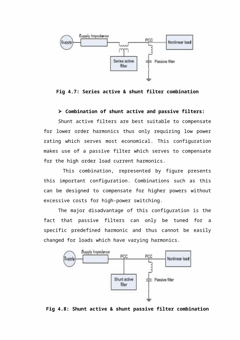
Combination of series active and shunt passive filters:
The combination of the active parallel and active series filters was seen to be
very complex in control yielding a high cost. One method of reducing these problems
was to replace the parallel active filter with a passive structure. The series active filter,
which constitutes high impedance for high-frequency harmonics, is accompanied by a
parallel passive filter to provide a path for the harmonic currents of the load.
This combination, represented by figure, permits an improvement over the
characteristics of plain series active filters and the extension of their capabilities to
include current- harmonic reduction and voltage- harmonic elimination. Passive filters
are often easier and simple to implement and do not require any control circuit. This,
this deserves to be most beneficial.
Fig 4.7: Series active & shunt filter combination
Page 34
Combination of shunt active and passive filters:
Shunt active filters are best suitable to compensate for lower order harmonics
thus only requiring low power rating which serves most economical. This
configuration makes use of a passive filter which serves to compensate for the high
order load current harmonics.
This combination, represented by figure presents this important configuration.
Combinations such as this can be designed to compensate for higher powers without
excessive costs for high-power switching.
The major disadvantage of this configuration is the fact that passive filters can
only be tuned for a specific predefined harmonic and thus cannot be easily changed
for loads which have varying harmonics.
Fig 4.8: Shunt active & shunt passive filter combination
Active filter in series with shunt passive filters:
The combination of an active filter in series with a shunt passive filter is
considered a significant design configuration for medium and high voltage
applications. The passive filter is designed to reduce the voltage stress applied to the
switches in the active filter. This design is in its infancy of development however,
further research is still needed to assess the effectiveness of the configuration.
Fig 4.9: Active filter in series with shunt passive filter combination
Page 35
5. DISTRIBUTION SYSTEM
Electrical power is transmitted by high voltage transmission lines from
sending end substation to receiving end substation. At the receiving end substation,
the voltage is stepped down to a lower value (say 66kV or 33kV or 11kV). The
secondary transmission system transfers power from this receiving end substation to
secondary sub-station. A secondary substation consists of two or more power
transformers together with voltage regulating equipments, buses and switchgear. At
the secondary substation voltage is stepped down to 11kV. The portion of the power
network between a secondary substation and consumers is known as distribution
system. The distribution system can be classified into primary and secondary system.
Some large consumers are given high voltage supply from the receiving end
substations or secondary substation.
The area served by a secondary substation can be subdivided into a number of
sub- areas. Each sub area has its primary and secondary distribution system. The
primary distribution system consists of main feeders and laterals. The main feeder
runs from the low voltage bus of the secondary substation and acts as the main source
of supply to sub- feeders, laterals or direct connected distribution transformers. The
lateral is supplied by the main feeder and extends through the load area with
connection to distribution transformers. The distribution transformers are located at
convenient places in the load area. They may be located in specially constructed
enclosures or may be pole mounted.
The distribution transformers for a large multi storied building may be located
within the building itself. At the distribution transformer, the voltage is stepped down
to 400V and power is fed into the secondary distribution systems. The secondary 14
distribution system consists of distributors which are laid along the road sides. The
service connections to consumers are tapped off from the distributors. The main
feeders, laterals and distributors may consist of overhead lines or cables or both. The
distributors are 3- phase, 4 wire circuits, the neutral wire being necessary to supply
the single phase loads. Most of the residential and commercial consumers are given
single phase supply. Some large residential and commercial consumer uses 3-phase
power supply. The service connections of consumer are known as service mains. The
consumer receives power from the distribution system.
5.1 Classification of Distribution System:
Page 36
A distribution system may be classified according to:
5.1.1 Nature of current:
According to nature of current, distribution system may be classified as (a)
d.c. distribution system and (b) a.c. distribution system. Now-a-days a.c. system is
universally adopted for distribution of electric power as it is simpler and more
economical than direct current method.
5.1.2 Type of construction:
According to type of construction, distribution system may be classified as (a)
overhead system and (b) underground system. The overhead system is generally
employed for distribution as it is 5 to 10 times cheaper than the equivalent
underground system. In general, the underground system is used at places where
overhead construction is impracticable or prohibited by the local laws.
5.1.3 Scheme of connection:
According to scheme of connection, the distribution system may be classified
as (a) radial system, (b) ring main system and (c) inter-connected system.
a. Radial System:
The system is the simplest and lowest in first cost. In this system of distribution the
distributors are fed at one end only. This system is employed when electrical energy is
generated at low voltage and the power station is situated at the centre of the load.
This system is not generally used due to its following disadvantages.
The end of the distributor nearest to the supply end would be heavily loaded.
The consumers at the farthest end of the distributor would be subjected to serious
voltage fluctuations with the variations in load.
Page 37
Fig 5.1: (i) A.C Distribution System & (ii) D.C Distribution System
b. The Ring Main System:
In this system each consumer is supplied via two feeders. The arrangement is similar
to two feeders in parallel on different routes. The advantages of this system over
radial system are
Less copper is required as each part of the ring carries less current than that in
radial system.
Less voltage fluctuations.
It is more reliable. In the event of fault on any one section the continuity of supply
to all consumers can be maintained by isolating the faulty section.
Fig 5.2: Ring main system
c. Interconnected System:
Page 38
When two or more generating stations are connected together, the system is
known as interconnected system. The main advantage of this system is that any area
fed from one generating station during overload hours can be fed from another power
stations and thus reserved capacity required is reduced, reliability of supply is
increased and load factor and efficiency is increased.
Fig 5.3: Interconnected System
Page 39
6. RENEWABLE ENERGY SOURCES
Energy that comes from resources which are naturally replenished on a human
timescale such as sunlight, wind, rain, tides, waves and geothermal heat is termed as
renewable energy. The most common definition is that renewable energy is from an
energy resource that is replaced by a natural process at a rate that is equal to or faster
than the rate at which that resource is being consumed. Renewable energy is a subset
of sustainable energy.
6.1 Renewable Energy Development in India:
India has done a significant progress in the power generation in the country.
The installed generation capacity was 1300 megawatt (MW) at the time of
Independence i.e. about 60 year’s back. The total generating capacity anticipated at
the end of the Tenth Plan on 31-03-2007, is 1, 44,520 MW which includes the
generation through various sectors like Hydro, Thermal and Nuclear. The power
generation in the country is planned through funds provided by the Central Sector,
State Sector and Private Sector.
The power shortages noticed is of the order of 11%. In the opinion of the
experts such short fall can be reduced through proper management and thus almost
40% energy can be saved. It has been noticed that one watt saved at the point of
consumption is more than 1.5 watts generated. In terms of Investment it costs around
Rs.40 million to generate one MW of new generation plant, but if the same Rs.40
million is spent on conservation of energy methods, it can provide up to 3 MW of
avoidable generation capacity.
There are about 80,000 villages yet to be electrified for which provision has
been made to electrify 62,000 villages from grid supply in the Tenth Plan. It is
planned that participation of decentralized power producers shall be ensured,
particularly for electrification of remote villages in which village level organizations
shall play a crucial role for the rural electrification programme.
Since the availability of fossil fuel is on the decline therefore, in this backdrop
the norms for conventional or renewable sources of energy (RSE) is given importance
not only in India but has attracted the global attention.
Page 40
Evolution of power transformer technology in the country during the past five
decades is quite impressive. There are manufacturers in the country with full access to
the latest technology at the global level. Some of the manufacturers have impressive
R&D set up to support the technology.
It has been felt that there is rising demand for energy, food and raw materials
by a population of 2.5 billion Chinese and Indians. Both these countries have large
coal dominated energy systems in the world and the use of fossil fuels such as coal
and oil releases carbon dioxide (Co2) into the air which adds to the greenhouse gases
which lead to global warming.
6.2 Main types of renewable energy sources:
The main items under RSE are as follows:
1. Hydro Power
2. Solar Power
3. Wind Power
4. Bio-mass Power
5. Energy from waste
6. Ocean energy
7. Alternative fuel for surface transportation
1. Hydro Power:
India is endowed with a large potential of hydro power, of which only 17%
has been harnessed so far. The hydro electricity is a clean and renewable source of
energy. It has been felt that there is a long gestation period in hydro projects due to
delays in forest and environment clearance, rehabilitation of the project effected
people besides inter-state disputes and construction holdups due to several reasons.
Under RSE only small hydro projects are considered since they do not require large
pond age and have the capacity to provide power to remote and hilly terrain where
extension of the grid system is either un-economic or not possible.
2. Solar Power:
Page 41
The climatic condition in India provides abundant potential of solar power due
to large scale radiation available during a wider part of the year due to tropical
condition in the country. The solar power can be developed for long term use through
the application of solar photo- voltaic (SPV) Technology which provides a potential
of 20MW per sq. Km. The other method for Utilization of solar energy is through the
adoption of solar thermal Technology. The programmes are under way to utilize SPV
by connecting to grid power systems.
The solar thermal devices are widely used in the country for various purposes
such as solar water heaters, solar cookers, solar dryers etc. There is wide scope for
development of solar thermal application for which the research is in progress. The
energy obtained through Solar Thermal route is 35 MW per sq. km.
3. Wind Power:
The wind power development in the country is largely of recent period which
has been found to be quite impressive. As per available data, it is 5340 MW by March
31, 2006, through wind power. Earlier it was estimated that the potential for wind
power in the country was 20,000 MW which has been revised to 45000MW after
collecting the data on the potential available in the coastal and other areas of the
country.
At present India is fifth in the world after Germany, USA, Denmark and Spain
in terms of wind power. It has been observed that the private sector is showing
interest in setting of wind power projects.
The unit size of wind turbine generators which were earlier in the range of 55-
100 kw are now preferred in the range of 750-1000 kw. It has been observed that the
productivity of the larger machine is higher as compared to the smaller machine. In
respect of cost consideration, it has been noticed that the cost of such a project is
about Rs.40 million to Rs.50 million per MW which includes all local civil, electrical
works and erection also. The life of a wind power project is estimated to be about 20
years.
4. Bio-mass Power:
There is quite a high energy potential available in the country in resources
such as firewood, agro-residues and animal wastes. These resources are mainly
utilized by the rural population of the country. It has been estimated that there is a
Page 42
potential to install 19500 MW capacity through biomass conservation technologies
like combustion, gasification, incineration and also bagasse – based co- generation in
sugar mills. So far only around 380 MW of this potential has been tapped and there is
wide scope for expanding the size of their use for the benefit of the majority of the
rural population to meet their energy needs.
5. Energy from Waste:
It has been estimated that there is about 30 million tones by solid waste and
4400 million cubic meters of liquid waste generated every year in urban areas through
domestic as well as commercial establishment. The manufacturing sector also
contributes high quantity of waste. It has been estimated that through garbage there is
a potential to generate 1700 MW of electricity. However all these activities are still to
be given a practical shape.
6. Ocean Energy:
The Ocean on the earth covers about 71% of the total surface which collects
and store solar energy. If this energy is quantified in terms of Oil, it can be said that
an amount of solar radiation equivalent in heat content to about 245 billion barrels of
oil is absorbed by the sea. The energy available in the Ocean is clean, continuous and
renewable. In future it would be possible to tap energy from the sea.
7. Alternative fuel for surface transportation:
Hydrocarbons used as fuels for transportation are to be replaced by other eco-
friendly fuels for surface transport vehicles. Many options such as compressed natural
gas (CNG), battery – powered vehicles and fuel cells are currently available.
The use of diesel in transportation in Delhi was causing pollution in the air.
The Government has adopted CNG use for all vehicles using diesel fuel, which has
improved the environment significantly.
Reliability in distribution system can be brought about by incorporating following
steps.
Use transformers, which have minimum maintenance problems.
Page 43
Improve power factor of the system.
Ensure proper protection to the system.
Neutral grounding system should be effective.
Introduce maintenance free equipment like Vacuum Circuit Breakers for all 11
KV feeders with auto re-closers.
Undertake preventive maintenance and avoid emergencies.
6.3 Global warming and climate change:
It has been felt that there is raising demand for energy, food and raw materials
by a population of 2.5 billion Chinese and Indians. Both these countries have large
coal dominated energy systems in the world and the use of fossil fuels such as coal
and oil releases carbon dioxide (Co2) into the air which adds to the greenhouse gases
which lead to global warming. At present US is the largest contributor of Co2
emissions but the development in India and China is going to increase their share in
emission of such a gas. According to Kyoto Protocol this has to be controlled. Climate
change shall be a cause of extinction of many bird varieties and other animals on the
earth.
Renewable source of energy is the best solution for such a problem in the
world. Both India and China are trying to develop their technology in this regard.
India has the world’s fourth largest wind power industry, while China is the
global leader in harnessing solar energy for hot water.
Wind Power could generate almost 29 percent of the world’s electricity by
2030 and was growing faster than any other clean energy source, a wind business
group and environmental lobby Greenpeace said. ‘At good locations wind can
compete with the cost of both coal and gas-fired Power’ the Global Wind Energy
Council (GWEC) and Greenpeace said in a study, ‘Global Wind Energy Outlook
2006’.The two said that wind, which now accounts for 0.8 percent of the world’s
electricity supply, was expanding faster than other renewable energies such as solar,
geothermal or tidal power in a shift from fossil fuels.
There have been cases of farmers committing suicides due to poverty and
failure of crop in some parts of India. A World Bank study released has found a
correlation between climate change and farmer suicides. It says poor farmers who are
Page 44
unable to adapt to changing climates fall into debt and later, death traps. It can be
surmised that energy development should be preferable by adopting measures which
does not give rise to greenhouse gasses as it would effect change in climate leading to
overall difficulties to the people who are accustomed to the climate as prevailing on
the earth.
Page 45
7. VOLTAGE SOURCE INVERTER
7.1 SINGLE-PHASE VOLTAGE SOURCE INVERTERS:
Single-phase voltage source inverters (VSIs) can be found as half-bridge and
full-bridge topologies. Although the power range they cover is the low one, they are
widely used in power supplies, single-phase UPSs, and currently to form elaborate
high-power static power topologies, such as for instance, the multi cell configurations
that are reviewed in Section 8.7. The main features of both approaches are reviewed
and presented in the following.
7.2 HALF-BRIDGE VSI:
Figure 7.1 shows the power topology of a half-bridge VSI, where two large
capacitors are required to provide a neutral point N, such that each capacitor
maintains a constant voltage vi=2. Because the current harmonics injected by the
operation of the inverter are low-order harmonics, a set of large capacitors (C. and
Cÿ) is required. It is clear that both switches S.
And Sÿ cannot be on simultaneously because a short circuit across the dc link
voltage source vi would be produced. There are two defined (states 1 and 2) and one
undefined (state 3) switch state as shown in Table 1. In order to avoid the short circuit
across the dc bus and the undefined ac output voltage condition, the modulating
technique should always ensure that at any instant either the top or the bottom switch
of the inverter leg is ON.
Fig 7.1: Single-phase half-bridge VSI
TABLE 1: Switch states for a half-bridge single-phase VSI
Page 46
7.3 Full-Bridge VSI:
Fig 7.2: Single-phase full-bridge VSI
Figure 7.2 shows the power topology of a full-bridge VSI. This inverter is
similar to the half-bridge inverter; however, a second leg provides the neutral point to
the load. As expected, both switches and (or and ) cannot be on
simultaneously because a short circuit across the dc link voltage source vi would be
produced. There are four defined (states 1, 2, 3, and 4) and one undefined (state 5)
switch states as shown in Table 2.
The undefined condition should be avoided so as to be always capable of
defining the ac output voltage. In order to avoid the short circuit across the dc bus and
the undefined ac output voltage condition, the modulating technique should ensure
that either the top or the bottom switch of each leg is on at any instant. It can be
observed that the ac output voltage can take values up to the dc link value vi , which
is twice that obtained with half-bridge VSI topologies. Several modulating techniques
have been developed that are applicable to full-bridge VSIs. Among them are the
PWM (bipolar and unipolar) techniques.
Page 47
TABLE 2: Switch states for a full-bridge single-phase VSI
Page 48
8. MODELING OF CASE STUDY
8.1 System Description:
The proposed system consists of RES connected to the dc-link of a grid-
interfacing inverter as shown in Fig 8.1. The voltage source inverter is a key element
of a DG system as it interfaces the renewable energy source to the grid and delivers
the generated power. The RES may be a DC source or an AC source with rectifier
coupled to dc-link. Usually, the fuel cell and photovoltaic energy sources generate
power at variable low dc voltage, while the variable speed wind turbines generate
power at variable ac voltage. Thus, the power generated from these renewable sources
needs power conditioning (i.e., dc/dc or ac/dc) before connecting on dc-link. The dc-
capacitor decouples the RES from grid and also allows independent control of
converters on either side of dc-link.
Fig 8.1: Schematic of proposed renewable based distributed generation system
8.2 DC-Link Voltage and Power Control Operation:
Due to the intermittent nature of RES, the generated power is of variable
nature. The dc-link plays an important role in transferring this variable power from
Page 49
renewable energy source to the grid. RES are represented as current sources
connected to the dc-link of a grid-interfacing inverter.
Fig 8.2 shows the systematic representation of power transfer from the
renewable energy resources to the grid via the dc-link. The current injected by
renewable into dc-link at voltage level can be given as
Fig 8.2: DC-Link equivalent diagram
..................... (1)
Where is the power generated from RES.
The current flow on the other side of dc-link can be represented as,
………………. (2)
Where and are total power available at grid-interfacing
inverter side, active power supplied to the grid and inverter losses, respectively. If
inverter losses are negligible then .
8.3 Control of Grid Interfacing Inverter:
The control diagram of grid- interfacing inverter for a 3-phase 4-wire system
is shown in Fig 8.3. The fourth leg of inverter is used to compensate the neutral
current of load. The main aim of proposed approach is to regulate the power at PCC
during: 1) ; 2) PRES< total load power (PL) ; and 3) PRES > PL.
Page 50
Fig 8.3: Block diagram representation of grid-interfacing inverter control
While performing the power management operation, the inverter is actively
controlled in such a way that it always draws/ supplies fundamental active power
from/ to the grid. If the load connected to the PCC is non-linear or unbalanced or the
combination of both, the given control approach also compensates the harmonics,
unbalance, and neutral current. The duty ratio of inverter switches are varied in a
power cycle such that the combination of load and inverter injected power appears as
balanced resistive load to the grid. The regulation of dc-link voltage carries the
information regarding the exchange of active power in between renewable source and
grid. Thus the output of dc-link voltage regulator results in an active current Im. The
multiplication of active current component (Im) with unity grid voltage vector
templates (Ua, Ub and Uc) generates the reference grid currents (Ia* , Ib
* and Ic*). The
reference grid neutral current (In*) is set to zero, being the instantaneous sum of
balanced grid currents. The grid synchronizing angle (θ) obtained from phase locked
loop (PLL) is used to generate unity vector template.
……………. (3)
……………. (4)
……………. (5)
The actual dc-link voltage (Vdc) is sensed and passed through a first-order low pass
filter (LPF) to eliminate the presence of switching ripples on the dc-link voltage and
Page 51
in the generated reference current signals. The difference of this filtered dc-link
voltage and reference dc-link voltage (Vdc*) is given to a discrete- PI regulator to
maintain a constant dc-link voltage under varying generation and load conditions. The
dc-link voltage error (Vdcerr (n)) at nth sampling instant is given as:
………….. (6)
The output of discrete-PI regulator at nth sampling instant is expressed as
……… (7)
Where and are proportional and integral gains of dc-
voltage regulator. The instantaneous values of reference three phase grid currents are
computed as
……………. (8)
………….. (9)
…………. (10)
The neutral current, present if any, due to the loads connected to the neutral conductor
should be compensated by forth leg of grid-interfacing inverter and thus should not be
drawn from the grid. In other words, the reference current for the grid neutral current
is considered as zero and can be expressed as
………… (11)
The reference grid currents (Ia* , Ib
* ,Ic* and In
*)are compared with actual grid currents
(Ia* , Ib
* ,Ic* and In
*) to compute the current errors as
……………. (12)
……………… (13)
………………. (14)
………………. (15)
These current errors are given to hysteresis current controller. The hysteresis
controller then generates the switching pulses (P1 to Pg ) for the gate drives of grid-
interfacing inverter. The average model of 4-leg inverter can be obtained by the
following state space equations
……………….. (16)
Page 52
…………….. (17)
………………… (18)
……………. (19)
…………. (20)
Where , and are the three-phase ac switching voltages
generated on the output terminal of inverter. These inverter output voltages can be
modeled in terms of instantaneous dc bus voltage and switching pulses of the inverter
as
………………. (21)
…………….. (22)
……………….. (23)
………………… (24)
Similarly the charging currents , and on dc bus
due to the each leg of inverter can be expressed as
……….. (25)
………….. (26)
……………. (27)
………………. (28)
The switching pattern of each IGBT inside inverter can be formulated On the basis of
error between actual and reference current of inverter, which can be explained as:
If , then upper switch will be OFF and
lower switch will be ON in the phase “a” leg of inverter. If
, then upper switch will be ON and lower switch
will be OFF in the phase “a” leg of inverter.
Page 53
Where hb is the width of hysteresis band. On the same principle, the switching
pulses for the other remaining three legs can be derived.
Page 54
9. MATLAB
Matlab is a high-performance language for technical computing. It integrates
computation, visualization, and programming in an easy-to-use environment where
problems and solutions are expressed in familiar mathematical notation. Typical uses
include Math and computation Algorithm development Data acquisition Modeling,
simulation, and prototyping Data analysis, exploration, and visualization Scientific
and engineering graphics Application development, including graphical user interface
building.
The name matlab stands for matrix laboratory. Matlab was originally written
to provide easy access to matrix software developed by the linpack and eispack
projects. Today, matlab engines incorporate the lapack and blas libraries, embedding
the state of the art in software for matrix computation.
Matlab features a family of add-on application-specific solutions called
toolboxes. Very important to most users of matlab, toolboxes allow you to learn and
apply specialized technology.
Toolboxes are comprehensive collections of matlab functions (M-files) that
extend the matlab environment to solve particular classes of problems. Areas in which
toolboxes are available include signal processing, control systems, neural networks,
fuzzy logic, wavelets, simulation, and many others.
The matlab system consists of five main parts,
Development Environment:
This is the set of tools and facilities that help you use matlab functions and
files. Many of these tools are graphical user interfaces. It includes the matlab desktop
and Command Window, a command history, an editor and debugger, and browsers for
viewing help, the workspace, files, and the search path.
Page 55
The matlab Mathematical Function Library:
This is a vast collection of computational algorithms ranging from elementary
functions, like sum, sine, cosine, and complex arithmetic, to more sophisticated
functions like matrix inverse, matrix eigenvalues, Bessel functions, and fast Fourier
transforms.
The matlab Language:
This is a high-level matrix/array language with control flow statements,
functions, data structures, input/output, and object-oriented programming features. It
allows both "programming in the small" to rapidly create quick and dirty throw-away
programs, and "programming in the large" to create large and complex application
programs.
Matlab has extensive facilities for displaying vectors and matrices as graphs,
as well as annotating and printing these graphs. It includes high-level functions for
two-dimensional and three-dimensional data visualization, image processing,
animation, and presentation graphics. It also includes low-level functions that allow
you to fully customize the appearance of graphics as well as to build complete
graphical user interfaces on your matlab applications.
The matlab Application Program Interface (API):
This is a library that allows you to write C and Fortran programs that interact with
matlab. It includes facilities for calling routines from matlab (dynamic linking),
calling matlab as a computational engine, and for reading and writing MAT-files.
Page 56
10. SIMULINK
10.1 Introduction:
Simulink is a software add-on to matlab which is a mathematical tool
developed by The Math works,(http://www.mathworks.com) a company based in
Natick. Matlab is powered by extensive numerical analysis capability. Simulink is a
tool used to visually program a dynamic system (those governed by Differential
equations) and look at results. Any logic circuit, or control system for a dynamic
system can be built by using standard building blocks available in Simulink Libraries.
Various toolboxes for different techniques, such as Fuzzy Logic, Neural Networks,
dsp, Statistics etc. are available with Simulink, which enhance the processing power
of the tool. The main advantage is the availability of templates / building blocks,
which avoid the necessity of typing code for small mathematical processes.
Concept of signal and logic flow:
In Simulink, data/information from various blocks are sent to another block by
lines connecting the relevant blocks. Signals can be generated and fed into blocks
dynamic / static).Data can be fed into functions. Data can then be dumped into sinks,
which could be scopes, displays or could be saved to a file. Data can be connected
from one block to another, can be branched, multiplexed etc.
In simulation, data is processed and transferred only at Discrete times, since
all computers are discrete systems. Thus, a simulation time step (otherwise called an
integration time step) is essential, and the selection of that step is determined by the
fastest dynamics in the simulated system.
Page 57
Fig 10.1: Simulink library browser
Connecting blocks:
Fig 10.2: Connecting blocks
To connect the blocks, do left-click and drag the mouse from the output of one
block to the input of another block.
Page 58
Sources and sinks:
The sources library contains the sources of data/signals that one would use in a
dynamic system simulation. One may want to use a constant input, a sinusoidal wave,
a step, a repeating sequence such as a pulse train, a ramp etc. One may want to test
disturbance effects, and can use the random signal generator to simulate noise. The
clock may be used to create a time index for plotting purposes. The ground could be
used to connect to any unused port, to avoid warning messages indicating
unconnected ports.
The sinks are blocks where signals are terminated or ultimately used. In most
cases, we would want to store the resulting data in a file, or a matrix of variables. The
data could be displayed or even stored to a file. the stop block could be used to stop
the simulation if the input to that block (the signal being sunk) is non-zero. Figure 3
shows the available blocks in the sources and sinks libraries.
Fig 10.3: Sources and sinks
Continuous and discrete systems:
All dynamic systems can be analyzed as continuous or discrete time systems.
Simulink allows you to represent these systems using transfer functions, integration
blocks, delay blocks etc.
Page 59
Non-linear operators:
` A main advantage of using tools such as Simulink is the ability to simulate
non-linear systems and arrive at results without having to solve analytically. It is very
difficult to arrive at an analytical solution for a system having non-linearities such as
saturation, signup function, limited slew rates etc. In Simulation, since systems are
analyzed using iterations, non-linearities are not a hindrance. One such could be a
saturation block, to indicate a physical limitation on a parameter, such as a voltage
signal to a motor etc. Manual switches are useful when trying simulations with
different cases. Switches are the logical equivalent of if-then statements in
programming.
Fig 10.4: Simulink blocks
Mathematical operations:
Mathematical operators such as products, sum, logical operations such as and,
or, etc. can be programmed along with the signal flow. Matrix multiplication becomes
easy with the matrix gain block. Trigonometric functions such as sin or tan inverse (at
an) are also available. Relational operators such as ‘equal to’, ‘greater than’ etc. can
also be used in logic circuits.
Page 60
10.2 Signals & data transfer:
In complicated block diagrams, there may arise the need to transfer data from
one portion to another portion of the block. They may be in different subsystems. That
signal could be dumped into a goto block, which is used to send signals from one
subsystem to another.
Multiplexing helps us remove clutter due to excessive connectors, and makes
matrix(column/row) visualization easier.
Fig 10.5: Signals and systems
Making subsystems:
Drag a subsystem from the Simulink Library Browser and place it in the
parent block where you would like to hide the code. The type of subsystem depends
on the purpose of the block. In general one will use the standard subsystem but other
subsystems can be chosen. For instance, the subsystem can be a triggered block,
which is enabled only when a trigger signal is received.
Open (double click) the subsystem and create input / output PORTS, which
transfer signals into and out of the subsystem. The input and output ports are created
Page 61
by dragging them from the Sources and Sinks directories respectively. When ports are
created in the subsystem, they automatically create ports on the external (parent)
block. This allows for connecting the appropriate signals from the parent block to the
subsystem.
Setting simulation parameters:
Running a simulation in the computer always requires a numerical technique
to solve a differential equation. The system can be simulated as a continuous system
or a discrete system based on the blocks inside. The simulation start and stop time can
be specified. In case of variable step size, the smallest and largest step size can be
specified. A Fixed step size is recommended and it allows for indexing time to a
precise number of points, thus controlling the size of the data vector. Simulation step
size must be decided based on the dynamics of the system. A thermal process may
warrant a step size of a few seconds, but a DC motor in the system may be quite fast
and may require a step size of a few milliseconds.
Page 62
11. MATLAB DESIGN OF CASE STUDY AND
RESULTS
Fig11.1: Simulation circuit
Page 63
Fig 11.2: Simulation results: (a) Grid voltages, (b) Grid
Currents (c) Unbalanced
load currents, (d) Inverter Currents
Page 64
Fig 11.3: Simulation results: (a) PQ-Grid, (b) PQ-Load, (c)
PQ-Inverter,
(d) dc-link voltage
Page 65
CONCLUSION
This project has presented a novel control of an existing grid interfacing
inverter to improve the quality of power at PCC for a 3-phase 4-wireDGsystem. It has
been shown that the grid-interfacing inverter can be effectively utilized for power
conditioning without affecting its normal operation of real power transfer. The grid-
interfacing inverter with the proposed approach can be utilized to:
i) Inject real power generated from RES to the grid, and/or,
ii) Operate as a shunt Active Power Filter (APF). This approach thus eliminates the
need for additional power conditioning equipment to improve the quality of power at
PCC. Extensive MATLAB/Simulink simulation as well as the DSP based
experimental results have validated the proposed approach and have shown that the
grid-interfacing inverter can be utilized as a multi-function device.
It is further demonstrated that the PQ enhancement can be achieved under
three different scenarios: 1) PRES=0, 2) PRES < PLoad, and 3) PRES > PLoad. The current
unbalance, current harmonics and load reactive power, due to unbalanced and non-
linear load connected to the PCC, are compensated effectively such that the grid side
currents are always maintained as balanced and sinusoidal at unity power factor.
Moreover, the load neutral current is prevented from flowing into the grid side by
compensating it locally from the fourth leg of inverter. When the power generated
from RES is more than the total load power demand, the grid-interfacing inverter with
the proposed control approach not only fulfills the total load active and reactive power
demand (with harmonic compensation) but also delivers the excess generated
sinusoidal active power to the grid at unity power factor.
Page 66
REFERENCES
[1] J. M. Guerrero, L. G. de Vicuna, J. Matas, M. Castilla, and J. Miret, “A wireless
controller to enhance dynamic performance of parallel inverters in distributed
generation systems,” IEEE Trans. Power Electron., vol. 19, no. 5, pp. 1205–1213,
Sep. 2004.
[2] J. H. R. Enslin and P. J. M. Heskes, “Harmonic interaction between a large
number of distributed power inverters and the distribution network,” IEEE Trans.
Power Electron., vol. 19, no. 6, pp. 1586–1593, Nov. 2004.
[3] U. Borup, F. Blaabjerg, and P. N. Enjeti, “Sharing of nonlinear load in parallel-
connected three-phase converters,” IEEE Trans. Ind. Appl., vol. 37, no. 6, pp. 1817–
1823, Nov./Dec. 2001.
[4] P. Jintakosonwit, H. Fujita, H. Akagi, and S. Ogasawara, “Implementation and
performance of cooperative control of shunt active filters for harmonic damping
throughout a power distribution system,” IEEE Trans. Ind. Appl., vol. 39, no. 2, pp.
556–564, Mar./Apr. 2003.
[5] J. P. Pinto, R. Pregitzer, L. F. C. Monteiro, and J. L. Afonso, “3-phase 4-wire
shunt asctive power filter with renewable energy interface,” presented at the Conf.
IEEE Renewable Energy & Power Quality, Seville, Spain, 2007.
[6] F. Blaabjerg, R. Teodorescu, M. Liserre, and A. V. Timbus, “Overview of control
and grid synchronization for distributed power generation systems,” IEEE Trans. Ind.
Electron., vol. 53, no. 5, pp. 1398–1409, Oct. 2006.