OR FORM WITHOUT THE WRITTEN APPROVAL OF GRIZZLY INDUSTRIAL, INC. #PC7741 PRINTED IN CHINA
Safety labels warn about machine hazards and ways to prevent injury. The owner of this machine MUST maintain the original location and readability of the labels on the machine. If any label is removed or becomes unreadable, REPLACE that label before using the machine again. Contact Grizzly at (800) 523-4777 or www.grizzly.com to order new labels.
Table of Contents
INTRODUCTION ............................................................................................................................... 3Foreword .................................................................................................................................... 3Contact Info ................................................................................................................................ 3Machine Data Sheet ................................................................................................................... 4Identification ............................................................................................................................... 6
SECTION 1: SAFETY ....................................................................................................................... 7Safety Instructions for Machinery ............................................................................................... 7Additional Safety for Mill/Drills .................................................................................................... 9
SECTION 3: SET UP ...................................................................................................................... 11Set Up Safety ........................................................................................................................... 11Items Needed for Set Up ......................................................................................................... 11Unpacking ................................................................................................................................ 11Inventory ................................................................................................................................... 12Clean Up .................................................................................................................................. 13Site Considerations .................................................................................................................. 13Feet .......................................................................................................................................... 14Mounting to Workbench ........................................................................................................... 14Test Run and Spindle Break-in ................................................................................................ 15Drill Chuck Removal ................................................................................................................. 16R-8 Collets ............................................................................................................................... 17
We are proud to offer the Model G0463 Small Mill/Drill. This machine is part of a growing Grizzly family of fine metalworking machinery. When used according to the guidelines set forth in this manual, you can expect years of trouble-free, enjoyable operation and proof of Grizzly’s com-mitment to customer satisfaction.
We are pleased to provide this manual with the Model G0463. It was written to guide you through assembly, review safety considerations, and cover general operating procedures. It repre-sents our effort to produce the best documenta-tion possible.
The specifications, drawings, and photographs illustrated in this manual represent the Model G0463 as supplied when the manual was pre-pared. However, owing to Grizzly’s policy of con-tinuous improvement, changes may be made at any time with no obligation on the part of Grizzly. For your convenience, we always keep current Grizzly manuals available on our website at www.grizzly.com. Any updates to your machine will be reflected in these manuals as soon as they are complete. Visit our site often to check for the lat-est updates to this manual!
-4- G0463 Small Mill/Drill
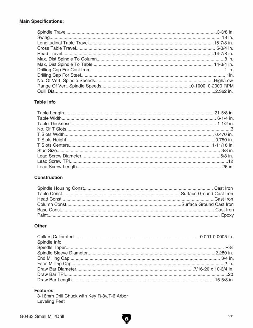
Product Dimensions:
Weight......................................................................................................................................... 353 lbs.Length/Width/Height................................................................................................. 27 x 30 x 33-3/4 in.Foot Print (Length/Width)........................................................................................................ 16 x 13 in.
Shipping Dimensions:
Type...................................................................................................................................... Wood CrateContent....................................................................................................................................... MachineWeight......................................................................................................................................... 372 lbs.Length/Width/Height....................................................................................................... 30 x 32 x 42 in.
Collars Calibrated....................................................................................................0.001-0.0005 in.Spindle InfoSpindle Taper............................................................................................................................. R-8Spindle Sleeve Diameter.....................................................................................................2.280 in.End Milling Cap....................................................................................................................... 3/4 in.Face Milling Cap.........................................................................................................................2 in.Draw Bar Diameter.............................................................................................7/16-20 x 10-3/4 in.Draw Bar TPI.................................................................................................................................20Draw Bar Length................................................................................................................ 15-5/8 in.
Features
3-16mm Drill Chuck with Key R-8/JT-6 ArborLeveling Feet
-6- G0463 Small Mill/Drill
Figure 1. G0463 Identification.
A. Emergency Stop Button B. Drawbar (under cover)C. High/Low Gear Change KnobD. Headstock LockE. Fuse SocketF. Spindle RPM ControlG. Forward/Reverse SwitchH. Main Power SwitchI. Quill Feed LeversJ. Graduated Dials
Identification
K. Longitudinal (X-Axis) HandwheelL. Vertical (Z Axis) HandwheelM. Adjustable FeetN. Cross (Y-Axis) HandwheelO. Table LocksP. Longitudinal ScaleQ. T-Slots and Coolant TroughR. Drill ChuckS. QuillT. Quill Lock
A
K
B C D E
F
G
H
I
T
S
R
Q
P
N
M L
J
O
G0463 Small Mill/Drill -7-
4. ALWAYS USE HEARING PROTECTION WHEN OPERATING MACHINERY. Machinery noise can cause permanent hearing damage.
5. WEAR PROPER APPAREL. DO NOT wear loose clothing, gloves, neckties, rings, or jewelry which may get caught in moving parts. Wear protective hair covering to con-tain long hair and wear non-slip footwear.
6. NEVER OPERATE MACHINERY WHEN TIRED, OR UNDER THE INFLUENCE OF DRUGS OR ALCOHOL. Be mentally alert at all times when running machinery.
1. READ THROUGH THE ENTIRE MANUAL BEFORE STARTING MACHINERY. Machinery presents serious injury hazards to untrained users.
2. ALWAYS USE ANSI APPROVED SAFETY GLASSES WHEN OPERATING MACHINERY. Everyday eyeglasses only have impact resistant lenses, they are NOT safety glasses.
3. ALWAYS WEAR AN ANSI APPROVED RESPIRATOR WHEN OPERATING MACHINERY THAT PRODUCES DUST. Wood dust is a carcinogen and can cause cancer and severe respiratory illnesses.
For Your Own Safety, Read Instruction Manual Before Operating this Machine
The purpose of safety symbols is to attract your attention to possible hazardous conditions. This manual uses a series of symbols and signal words which are intended to convey the level of importance of the safety messages. The progression of symbols is described below. Remember that safety messages by themselves do not eliminate danger and are not a substitute for proper accident prevention measures.
Indicates a potentially hazardous situation which, if not avoided, MAY result in minor or moderate injury. It may also be used to alert against unsafe practices.
Indicates a potentially hazardous situation which, if not avoided, COULD result in death or serious injury.
Indicates an imminently hazardous situation which, if not avoided, WILL result in death or serious injury.
This symbol is used to alert the user to useful information about proper operation of the machine.NOTICE
Safety Instructions for Machinery
SECTION 1: SAFETY
-8- G0463 Small Mill/Drill
7. ONLY ALLOW TRAINED AND PROP-ERLY SUPERVISED PERSONNEL TO OPERATE MACHINERY. Make sure operation instructions are safe and clearly understood.
8. KEEP CHILDREN AND VISITORS AWAY. Keep all children and visitors a safe dis-tance from the work area.
9. MAKE WORKSHOP CHILD PROOF. Use padlocks, master switches, and remove start switch keys.
10. NEVER LEAVE WHEN MACHINE IS RUNNING. Turn power OFF and allow all moving parts to come to a complete stop before leaving machine unattended.
11. DO NOT USE IN DANGEROUS ENVIRONMENTS. DO NOT use machin-ery in damp, wet locations, or where any flammable or noxious fumes may exist.
12. KEEP WORK AREA CLEAN AND WELL LIT. Clutter and dark shadows may cause accidents.
13. USE A GROUNDED EXTENSION CORD RATED FOR THE MACHINE AMPERAGE. Undersized cords overheat and lose power. Replace extension cords if they become damaged. DO NOT use extension cords for 220V machinery.
14. ALWAYS DISCONNECT FROM POWER SOURCE BEFORE SERVICING MACHINERY. Make sure switch is in OFF position before reconnecting.
15. MAINTAIN MACHINERY WITH CARE. Keep blades sharp and clean for best and safest performance. Follow instructions for lubricating and changing accessories.
16. MAKE SURE GUARDS ARE IN PLACE AND WORK CORRECTLY BEFORE USING MACHINERY.
Safety Instructions for Machinery17. REMOVE ADJUSTING KEYS AND
WRENCHES. Make a habit of checking for keys and adjusting wrenches before turn-ing machinery ON.
18. CHECK FOR DAMAGED PARTS BEFORE USING MACHINERY. Check for binding and alignment of parts, broken parts, part mounting, loose bolts, and any other conditions that may affect machine operation. Repair or replace damaged parts.
19. USE RECOMMENDED ACCESSORIES. Refer to the instruction manual for recom-mended accessories. The use of improper accessories may cause risk of injury.
20. DO NOT FORCE MACHINERY. Work at the speed for which the machine or acces-sory was designed.
21. SECURE WORKPIECE. Use clamps or a vise to hold the workpiece when practi-cal. A secured workpiece protects your hands and frees both hands to operate the machine.
22. DO NOT OVERREACH. Keep proper foot-ing and balance at all times.
23. MANY MACHINES WILL EJECT THE WORKPIECE TOWARD THE OPERATOR. Know and avoid conditions that cause the workpiece to "kickback."
24. ALWAYS LOCK MOBILE BASES (IF USED) BEFORE OPERATING MACHINERY.
25. BE AWARE THAT CERTAIN DUST MAY BE HAZARDOUS to the respiratory sys-tems of people and animals, especially fine dust. Make sure you know the hazards associated with the type of dust you will be exposed to and always wear a respirator approved for that type of dust.
G0463 Small Mill/Drill -9-
Additional Safety for Mill/Drills1. UNDERSTANDING CONTROLS. Make sure
you understand the use and operation of all controls.
2. SAFETY ACCESSORIES. Always use a chip guard in addition to your safety glasses when milling to prevent bodily injury.
3. WORK HOLDING. Before starting the machine, be certain the workpiece has been properly clamped to the table. NEVER hold the workpiece by hand when using the mill.
4. CHUCK KEY SAFETY. Always remove your chuck key, drawbar wrench, and any service tools immediately after use.
5. SPINDLE SPEEDS. Select the spindle speed that is appropriate for the type of work and material. Allow the mill/drill to gain full speed before beginning a cut.
6. POWER DISRUPTION. In the event of a local power outage during use of the mill, turn OFF all switches to avoid possible sud-den start up once power is restored.
7. SPINDLE DIRECTION CHANGES. Never reverse spindle direction while the mill/drill is in motion.
8. STOPPING SPINDLE. DO NOT stop the mill/drill using your hand against the chuck.
9. BE ATTENTIVE. DO NOT leave mill/drill run-ning unattended for any reason.
10. MACHINE CARE AND MAINTENANCE. Never operate the mill/drill with damaged or worn parts. Maintain your mill/drill in proper working condition. Perform routine inspec-tions and maintenance promptly. Put away adjustment tools after use.
11. DISCONNECT POWER. Make sure the mill is turned OFF, disconnected from its power source and all moving parts have come to a complete stop before starting any inspection, adjustment, or maintenance procedure.
12. AVOIDING ENTANGLEMENT. Keep loose clothing articles such as sleeves, belts or jew-elry items away from the mill spindle. Never wear gloves when operating the mill.
13. TOOL HOLDING. Always use the proper tools for the material you are milling. Make sure they are held firmly in the proper tool holder for the job.
14. CLEAN-UP. DO NOT clear chips by hand. Use a brush, and never clear chips while the mill is turning.
15. CUTTING TOOL INSPECTION. Inspect drills and end mills for sharpness, chips, or cracks before each use. Replace dull, chipped, or cracked cutting tools immediately. Handle new cutting tools with care. Leading edges are very sharp and can cause lacerations.
13. EXPERIENCING DIFFICULTIES. If at any time you are experiencing difficulties per-forming the intended operation, stop using the machine! Contact our Technical Support at (570) 546-9663.
No list of safety guidelines can be complete. Every shop environment is different. Like all machines there is danger associated with the Model G0463. Accidents are frequently caused by lack of familiarity or failure to pay attention. Use this machine with respect and caution to lessen the possibility of operator injury. If normal safety precautions are overlooked or ignored, serious personal injury may occur.
-10- G0463 Small Mill/Drill
Figure 2. A 5-15 plug and receptacle.
Serious personal injury could occur if you connect the machine to the power source before you have completed the set up pro-cess. DO NOT connect the machine to the power source until instructed to do so.
110V Operation
Amperage DrawThe Model G0463 motor draws the following amps under maximum load:
Motor Draw ..............................................7 Amps
Circuit RecommendationsWe recommend connecting this machine to a dedicated circuit with a verified ground, using the circuit breaker size given below. Never replace a circuit breaker with one of higher amperage with-out consulting a qualified electrician to ensure compliance with wiring codes. If you are unsure about the wiring codes in your area or you plan to connect your machine to a shared cir-cuit, you may create a fire hazard—consult a qualified electrician to reduce this risk.
Plug/Receptacle TypeIncluded Plug Type ........................... NEMA 5-15
This machine must have a ground prong in the plug to help ensure that it is grounded. DO NOT remove ground prong from plug to fit into a two-pronged outlet! If the plug will not fit the outlet, have the proper outlet installed by a qualified electrician.
Extension CordsWe do not recommend the use of extension cords, if you find it absolutely necessary:
• Use at least a 16 gauge cord that does not exceed 50 feet in length!
• The extension cord must also contain a ground wire and plug pin.
• A qualified electrician MUST size cords over 50 feet long to prevent motor damage.
SECTION 2: CIRCUIT REQUIREMENTS
Electrocution or fire could result if this machine is not grounded correctly or if your electrical configu-ration does not comply with local and state codes. Ensure compliance by checking with a qualified electrician!
G0463 Small Mill/Drill -11-
The Model G0463 was carefully packed when it left our warehouse. If you discover the machine is damaged after you have signed for delivery, please immediately call Customer Service at (570) 546-9663 for advice.
Save the containers and all packing materials for possible inspection by the carrier or its agent. Otherwise, filing a freight claim can be difficult.
When you are completely satisfied with the con-dition of your shipment, you should inventory the contents.
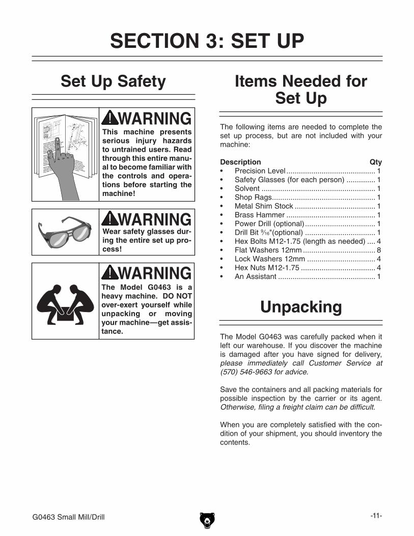
Wear safety glasses dur-ing the entire set up pro-cess!
This machine presents serious injury hazards to untrained users. Read through this entire manu-al to become familiar with the controls and opera-tions before starting the machine!
Unpacking
Set Up Safety
SECTION 3: SET UP
The Model G0463 is a heavy machine. DO NOT over-exert yourself while unpacking or moving your machine—get assis-tance.
The following items are needed to complete the set up process, but are not included with your machine:
Items not shown:Spare Fuse ........................................................ 1
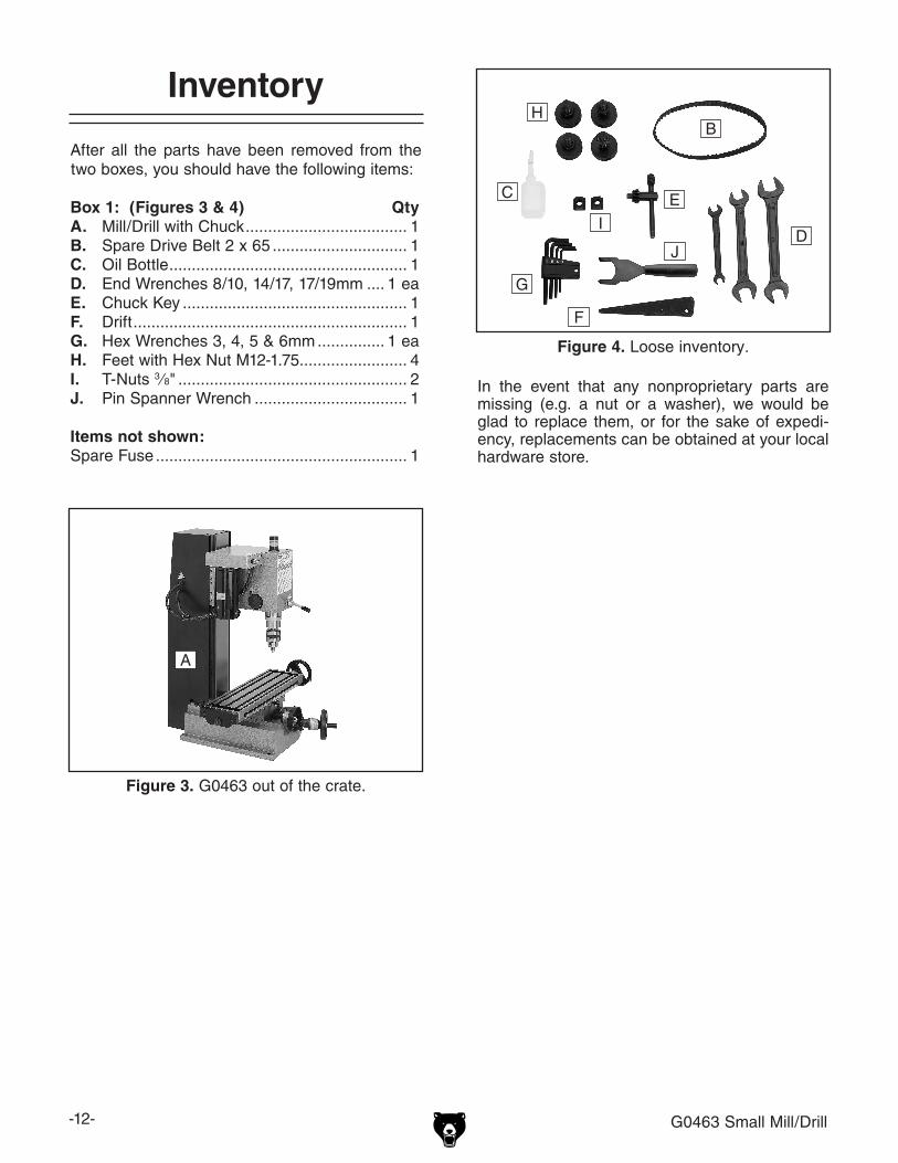
Figure 3. G0463 out of the crate.
In the event that any nonproprietary parts are missing (e.g. a nut or a washer), we would be glad to replace them, or for the sake of expedi-ency, replacements can be obtained at your local hardware store.
Figure 4. Loose inventory.
A
B
C
D
E
F
G
H
I
J
G0463 Small Mill/Drill -13-
Workbench LoadAlthough adjustable feet are included with your mill/drill, It is strongly recommended you bolt your machine to a sturdy workbench that will not tip. Refer to the Machine Data Sheet for the weight and footprint specifications of your machine. Some workbenches may require additional rein-forcement to support both the machine and the workpiece.
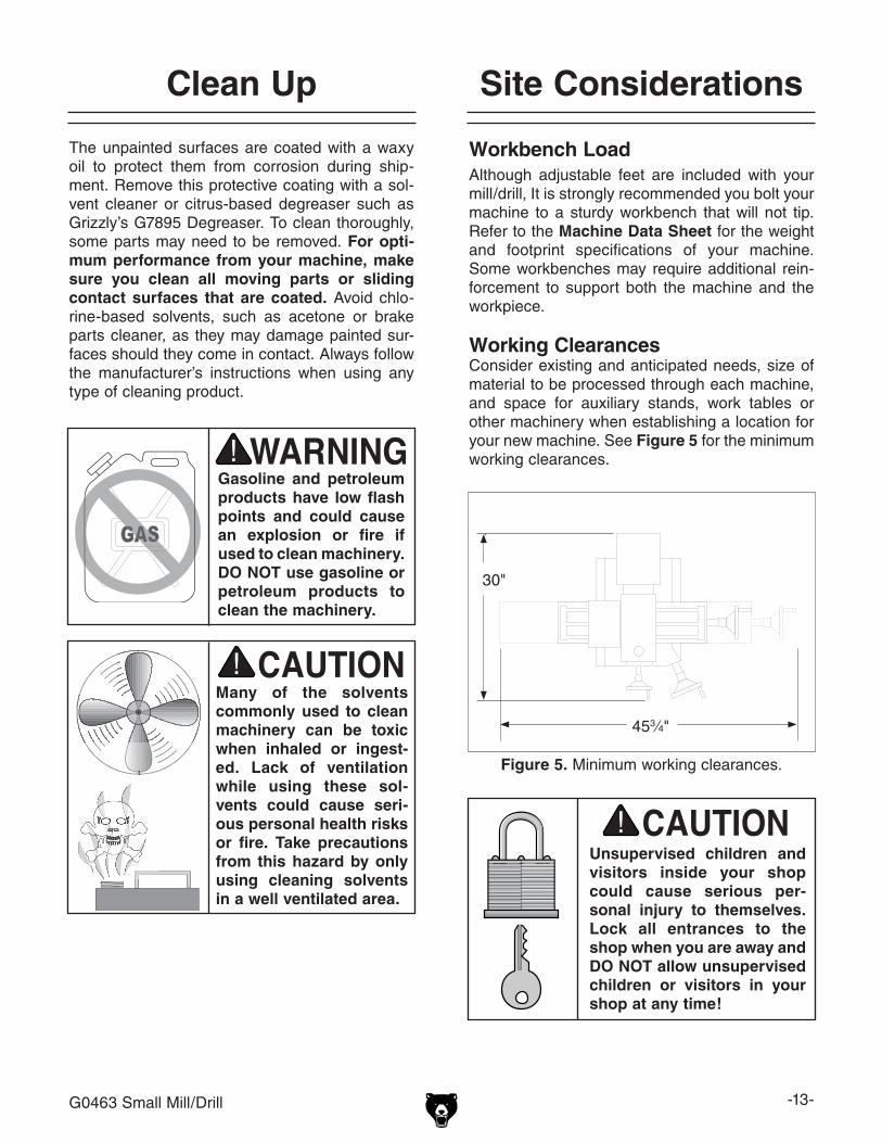
Working ClearancesConsider existing and anticipated needs, size of material to be processed through each machine, and space for auxiliary stands, work tables or other machinery when establishing a location for your new machine. See Figure 5 for the minimum working clearances.
Unsupervised children and visitors inside your shop could cause serious per-sonal injury to themselves. Lock all entrances to the shop when you are away and DO NOT allow unsupervised children or visitors in your shop at any time!
The unpainted surfaces are coated with a waxy oil to protect them from corrosion during ship-ment. Remove this protective coating with a sol-vent cleaner or citrus-based degreaser such as Grizzly’s G7895 Degreaser. To clean thoroughly, some parts may need to be removed. For opti-mum performance from your machine, make sure you clean all moving parts or sliding contact surfaces that are coated. Avoid chlo-rine-based solvents, such as acetone or brake parts cleaner, as they may damage painted sur-faces should they come in contact. Always follow the manufacturer’s instructions when using any type of cleaning product.
Site ConsiderationsClean Up
Gasoline and petroleum products have low flash points and could cause an explosion or fire if used to clean machinery. DO NOT use gasoline or petroleum products to clean the machinery.
Many of the solvents commonly used to clean machinery can be toxic when inhaled or ingest-ed. Lack of ventilation while using these sol-vents could cause seri-ous personal health risks or fire. Take precautions from this hazard by only using cleaning solvents in a well ventilated area.
Figure 5. Minimum working clearances.
453⁄4"
30"
-14- G0463 Small Mill/Drill
Feet
Four leveling feet have been included with your mill/drill. However, we recommend bolting your machine to a sturdy workbench.
Components and Hardware Needed: QtyFeet with Hex Nut M12-1.75 ............................... 4
To install the feet on the mill/drill:
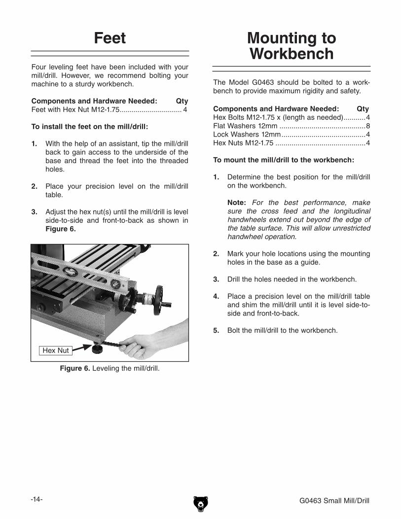
1. With the help of an assistant, tip the mill/drill back to gain access to the underside of the base and thread the feet into the threaded holes.
2. Place your precision level on the mill/drill table.
3. Adjust the hex nut(s) until the mill/drill is level side-to-side and front-to-back as shown in Figure 6.
Figure 6. Leveling the mill/drill.
Hex Nut
Mounting to Workbench
The Model G0463 should be bolted to a work-bench to provide maximum rigidity and safety.
Components and Hardware Needed: QtyHex Bolts M12-1.75 x (length as needed) ...........4Flat Washers 12mm ...........................................8Lock Washers 12mm ..........................................4Hex Nuts M12-1.75 .............................................4
To mount the mill/drill to the workbench:
1. Determine the best position for the mill/drill on the workbench.
Note: For the best performance, make
sure the cross feed and the longitudinal handwheels extend out beyond the edge of the table surface. This will allow unrestricted handwheel operation.
2. Mark your hole locations using the mounting holes in the base as a guide.
3. Drill the holes needed in the workbench.
4. Place a precision level on the mill/drill table and shim the mill/drill until it is level side-to-side and front-to-back.
5. Bolt the mill/drill to the workbench.
G0463 Small Mill/Drill -15-
Test Run and Spindle Break-in
The Model G0463 has two speed ranges: Low range is 0–1000; high range is 0–2000 RPM.
It is essential to closely follow the proper break-in procedures to ensure trouble free performance. Complete this process once you have familiarized yourself with all instructions in this manual.
To begin the start up and break-in procedure:
1. Follow all lubrication procedures highlighted in Lubrication in Section 6: MAINTENANCE on Page 24.
2. Make sure there are no obstructions around or underneath the spindle. Remove the drawbar if there is no arbor or collet in the spindle.
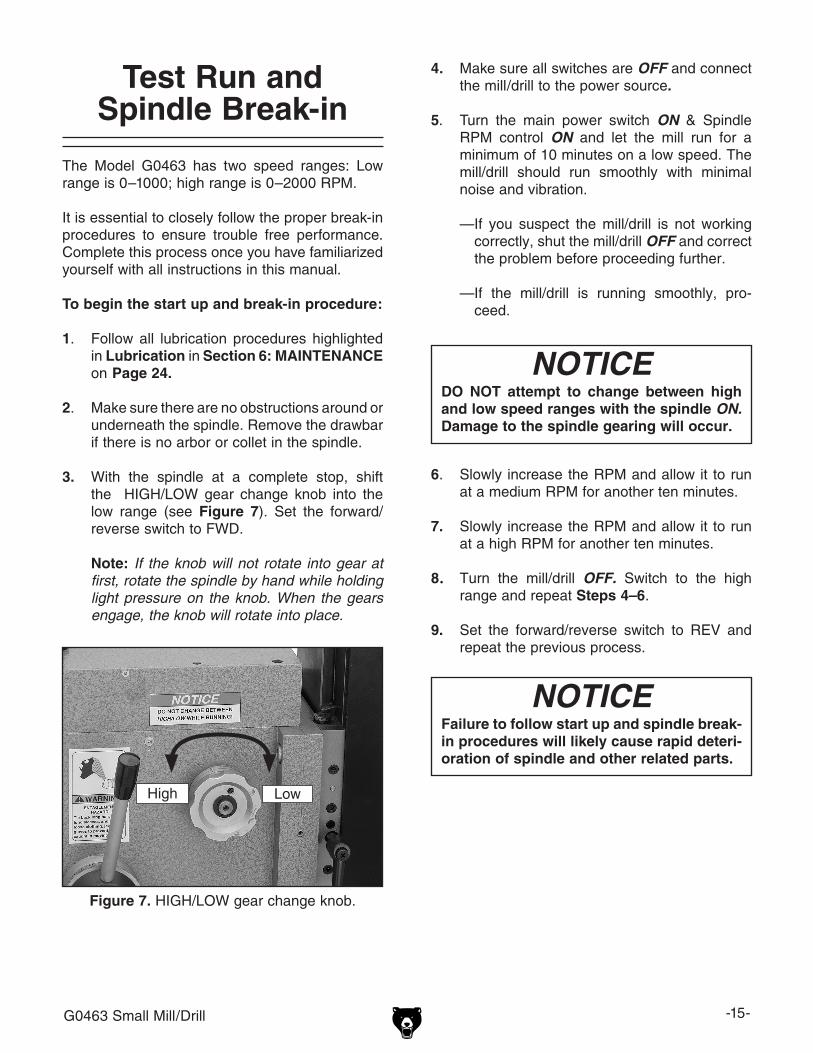
3. With the spindle at a complete stop, shift the HIGH/LOW gear change knob into the low range (see Figure 7). Set the forward/reverse switch to FWD.
Note: If the knob will not rotate into gear at first, rotate the spindle by hand while holding light pressure on the knob. When the gears engage, the knob will rotate into place.
Failure to follow start up and spindle break-in procedures will likely cause rapid deteri-oration of spindle and other related parts.
NOTICE
4. Make sure all switches are OFF and connect the mill/drill to the power source.
5. Turn the main power switch ON & Spindle RPM control ON and let the mill run for a minimum of 10 minutes on a low speed. The mill/drill should run smoothly with minimal noise and vibration.
—If you suspect the mill/drill is not working correctly, shut the mill/drill OFF and correct the problem before proceeding further.
—If the mill/drill is running smoothly, pro-ceed.
Figure 7. HIGH/LOW gear change knob.
6. Slowly increase the RPM and allow it to run at a medium RPM for another ten minutes.
7. Slowly increase the RPM and allow it to run at a high RPM for another ten minutes.
8. Turn the mill/drill OFF. Switch to the high
range and repeat Steps 4–6.
9. Set the forward/reverse switch to REV and repeat the previous process.
DO NOT attempt to change between high and low speed ranges with the spindle ON. Damage to the spindle gearing will occur.
NOTICE
High Low
-16- G0463 Small Mill/Drill
Figure 9. Striking the drawbar.
Drill Chuck Removal
The Model G0463 may have shipped with the drill chuck installed in the spindle. If this is the case, go ahead and remove the chuck and arbor at this time.
2. Remove the plastic cap that covers the drawbar.
3. Lock the quill in place with the quill lock. 4. Insert the pin spanner into the two holes at
the bottom of the spindle. This will keep the spindle from turning, and allow you to loosen the drawbar (see Figure 8).
NOTICEDO NOT completely unscrew the drawbar before striking it with the hammer. You will damage the threads on the drawbar and the arbor.
6. Tap the top of the drawbar with the hammer. This will unseat the taper of the arbor and the spindle (see Figure 9).
7. Hold one hand under the chuck and finish loosening the drawbar by hand until it falls out of the spindle.
Note: The chuck is attached to the arbor using a JT6 taper. This attachment is consid-ered to be semi-permanent. There should be no need to remove the chuck from the arbor. Inspect the chuck from time to time to make sure it is still tight on the arbor. If it is loose, use an dead-blow or other soft headed ham-mer to re-seat the taper.
5. Using the 17mm wrench, loosen the drawbar but DO NOT remove it.
Figure 8. Spindle holes.
Holes Under Spindle
G0463 Small Mill/Drill -17-
The Model G0463 features an R-8 spindle taper, which only accepts R-8 collets. R-8 collets come in many sizes, typically ranging from 1⁄16" to 7⁄8" and 3mm to 20mm. You will need a collet to match the diameter of the shank of the tool you want to hold.
To install the R-8 collet:
1. UNPLUG THE MILL/DRILL!
2. Remove the drawbar cap.
3. Carefully clean the surface of the collet and spindle taper. Ensure that it is free of debris, oil and grease of any kind.
4. Insert the cutting tool into the collet.
5. Insert the collet up into the spindle taper.
6. Slide the collet the rest of the way in until it makes contact with the threads at the end of the drawbar.
7. Using your fingers, thread the drawbar into the collet until the collet draws up into the spindle taper.
8. While supporting the tool in the collet with one hand, tighten the drawbar with the 17mm wrench in your opposite hand.
Note: Do not overtighten the drawbar. Overtightening makes collet removal dif-ficult and causes damage to the drawbar threads, collet, and the spindle taper. Keep in mind the taper keeps the collet and tool in place. The drawbar simply aids in seating the taper.
R-8 Collets To remove the collet:
1. UNPLUG THE MILL/DRILL!
2. Tighten the headstock lock.
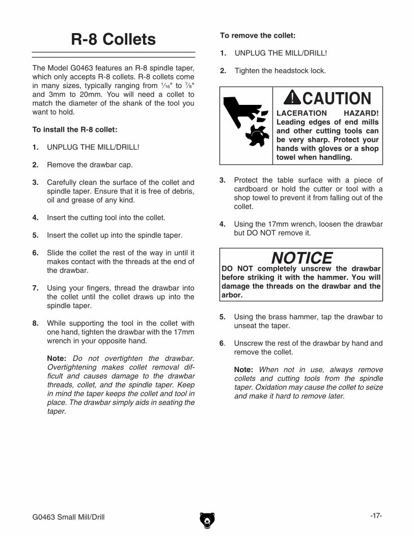
LACERATION HAZARD! Leading edges of end mills and other cutting tools can be very sharp. Protect your hands with gloves or a shop towel when handling.
NOTICEDO NOT completely unscrew the drawbar before striking it with the hammer. You will damage the threads on the drawbar and the arbor.
3. Protect the table surface with a piece of cardboard or hold the cutter or tool with a shop towel to prevent it from falling out of the collet.
4. Using the 17mm wrench, loosen the drawbar but DO NOT remove it.
5. Using the brass hammer, tap the drawbar to unseat the taper.
6. Unscrew the rest of the drawbar by hand and remove the collet.
Note: When not in use, always remove collets and cutting tools from the spindle taper. Oxidation may cause the collet to seize and make it hard to remove later.
-18- G0463 Small Mill/Drill
Damage to your eyes, lungs, and ears could result from using this machine without proper protective gear. Always wear safety glasses, a respirator, and hearing protection when operating this machine.
Loose hair and cloth-ing could get caught in machinery and cause seri-ous personal injury. Keep loose clothing and long hair away from moving machinery.
Operation Safety
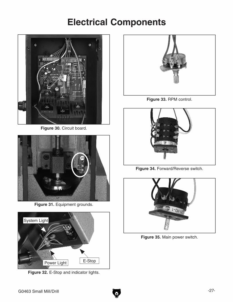
1. EMERGENCY STOP Button: Immediately disconnects power to the system. Once pressed, this button must be twisted until it pops out to return power to the switches. The FAULT INDICATOR Light will turn on and the MAIN POWER Switch needs to be turned OFF.
2. FAULT INDICATOR Light: Indicates a cir-cuit interruption due to a switch being out of proper position. Turn all switches OFF when lit.
3. POWER INDICATOR Light: Shines when the system power is ON.
4. Fuse Socket: Houses a 10 Amp system fuse.
SECTION 4: OPERATIONS
NOTICEIf you have never used this type of machine or equipment before, WE STRONGLY REC-OMMEND that you read books, trade maga-zines, or get formal training before begin-ning any projects. Regardless of the con-tent in this section, Grizzly Industrial will not be held liable for accidents caused by lack of training.
Power Controls
It is vital that you become familiar with the power controls before operating the Model G0463. Three separate switches control the power on the mill/drill (see Figure 10).
Figure 10. Control panel components.
5
7
4
3
1
6
2
G0463 Small Mill/Drill -19-
Power Shutdown
It is important to shut the power OFF when the mill/drill is not in use. Leaving the power ON keeps the circuit board cooling fan running. This will cause unnecessary wear on the fan and elec-trical system.
To completely shut the system power OFF:
1. Turn the SPINDLE RPM Control Knob OFF.
2. Turn the MAIN POWER Switch OFF.
3. Press the EMERGENCY STOP Button. At this point the green power light and the amber fan power light should not be lit.
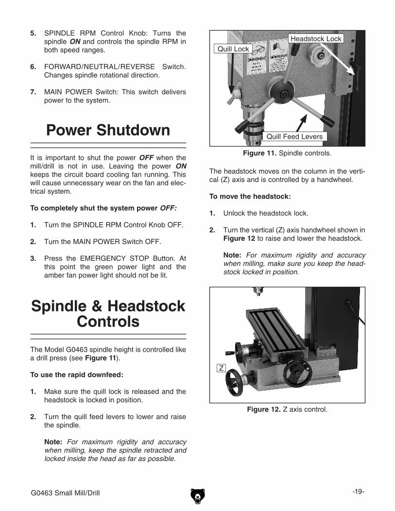
Figure 11. Spindle controls.
Spindle & Headstock Controls
The Model G0463 spindle height is controlled like a drill press (see Figure 11).
To use the rapid downfeed:
1. Make sure the quill lock is released and the headstock is locked in position.
2. Turn the quill feed levers to lower and raise the spindle.
Note: For maximum rigidity and accuracy when milling, keep the spindle retracted and locked inside the head as far as possible.
Headstock LockQuill Lock
Quill Feed Levers
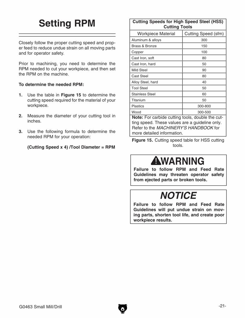
The headstock moves on the column in the verti-cal (Z) axis and is controlled by a handwheel.
To move the headstock:
1. Unlock the headstock lock.
2. Turn the vertical (Z) axis handwheel shown in Figure 12 to raise and lower the headstock.
Note: For maximum rigidity and accuracy when milling, make sure you keep the head-stock locked in position.
5. SPINDLE RPM Control Knob: Turns the spindle ON and controls the spindle RPM in both speed ranges.
7. MAIN POWER Switch: This switch delivers power to the system.
Figure 12. Z axis control.
Z
-20- G0463 Small Mill/Drill
Figure 14. Table locks.
Table Travel
The mill/drill table can be moved in the X and Y axis.
Longitudinal FeedThe longitudinal feed or (X-axis) is moved by a handwheel in Figure 13 at the end of the table. The handwheel will move the table in both direc-tions side-to-side. One complete revolution of the handwheel moves the longitudinal feed 0.100". There is also a scale on the front of the table for use when a tight tolerance is not required. The longitudinal feed can be locked in position by a table lock located on the front of the table (see Figure 14).
Cross FeedThe cross feed or (Y-axis) in Figure 13, is moved with the handwheel on the front of the table base. One complete revolution of the handwheel moves the cross slide 0.100". The cross feed can be locked into position by a table lock located on the right side of the cross slide underneath the table (see Figure 14).
Figure 13. X & Y Handwheels.
Table Locks
X
Y
G0463 Small Mill/Drill -21-
Setting RPM
Closely follow the proper cutting speed and prop-er feed to reduce undue strain on all moving parts and for operator safety.
Prior to machining, you need to determine the RPM needed to cut your workpiece, and then set the RPM on the machine.
To determine the needed RPM:
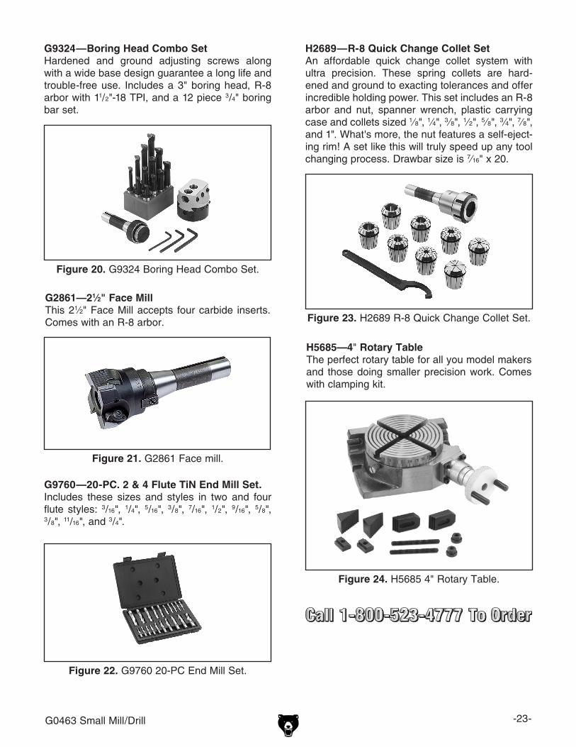
1. Use the table in Figure 15 to determine the cutting speed required for the material of your workpiece.
2. Measure the diameter of your cutting tool in inches.
3. Use the following formula to determine the needed RPM for your operation:
(Cutting Speed x 4) /Tool Diameter = RPM
Cutting Speeds for High Speed Steel (HSS) Cutting Tools
Workpiece Material Cutting Speed (sfm)Aluminum & alloys 300
Brass & Bronze 150
Copper 100
Cast Iron, soft 80
Cast Iron, hard 50
Mild Steel 90
Cast Steel 80
Alloy Steel, hard 40
Tool Steel 50
Stainless Steel 60
Titanium 50
Plastics 300-800
Wood 300-500
Note: For carbide cutting tools, double the cut-ting speed. These values are a guideline only. Refer to the MACHINERY'S HANDBOOK for more detailed information.
Figure 15. Cutting speed table for HSS cutting tools.
Failure to follow RPM and Feed Rate Guidelines may threaten operator safety from ejected parts or broken tools.
Failure to follow RPM and Feed Rate Guidelines will put undue strain on mov-ing parts, shorten tool life, and create poor workpiece results.
NOTICE
-22- G0463 Small Mill/Drill
SECTION 5: ACCESSORIESACCESSORIES
G9002—21⁄2" Swivel Base Milling ViseG5971— 31⁄2" Swivel Base Milling ViseG5972—4" Swivel Base Milling ViseG5973—5" Swivel Base Milling ViseG5974—6" Swivel Base Milling ViseG5975—8" Swivel Base Milling ViseVises feature 360° rotation with fine graduations, drop forged handle, precision ground jaw faces, enclosed acme screw and detachable swivel base.
Figure 19. Swivel base milling vise.
G9765—9-PC. Ball End Mill SetFeatures 2 flute ball nose end mills. Includes the following sizes: 1/8", 3/16", 1/4", 5/16", 3/8", 7/16", 1/2", 5/8" and 3/4".
Figure 16. G9765 9 PC. Ball End Mill Set.
Figure 17. Test Indicator.
G9610—Test Indicator .03" Range/.001" ResolutionG9611—Test Indicator.008" Range/.0001" ResolutionG9612—Test Indicator.030" Range/.0005" ResolutionThese test indicators have an easy to read dial and a pivoting stylus that moves at right angles to the dial face.
H3022—Measurement Tool SetIncludes magnetic base, 1" dial indicator (.001"), and 6" dial caliper (.001"). The extremely low price has made this a very popular seller!
Figure 18. H3022 Measurement Tool Set.
G0463 Small Mill/Drill -23-
Figure 21. G2861 Face mill.
G2861—21⁄2" Face MillThis 21⁄2" Face Mill accepts four carbide inserts. Comes with an R-8 arbor.
Figure 24. H5685 4" Rotary Table.
H5685—4" Rotary TableThe perfect rotary table for all you model makers and those doing smaller precision work. Comes with clamping kit.
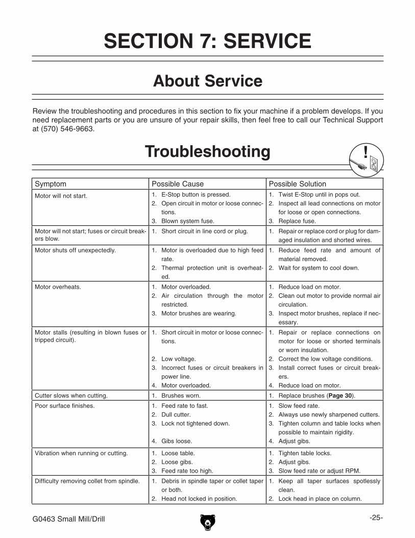
G9324—Boring Head Combo SetHardened and ground adjusting screws along with a wide base design guarantee a long life and trouble-free use. Includes a 3" boring head, R-8 arbor with 11/2"-18 TPI, and a 12 piece 3/4" boring bar set.
Figure 20. G9324 Boring Head Combo Set.
G9760—20-PC. 2 & 4 Flute TiN End Mill Set.Includes these sizes and styles in two and four flute styles: 3/16", 1/4", 5/16", 3/8", 7/16", 1/2", 9/16", 5/8", 3/8", 11/16", and 3/4".
Figure 22. G9760 20-PC End Mill Set.
Figure 23. H2689 R-8 Quick Change Collet Set.
H2689—R-8 Quick Change Collet SetAn affordable quick change collet system with ultra precision. These spring collets are hard-ened and ground to exacting tolerances and offer incredible holding power. This set includes an R-8 arbor and nut, spanner wrench, plastic carrying case and collets sized 1⁄8", 1⁄4", 3⁄8", 1⁄2", 5⁄8", 3⁄4", 7⁄8", and 1". What's more, the nut features a self-eject-ing rim! A set like this will truly speed up any tool changing process. Drawbar size is 7⁄16" x 20.
-24- G0463 Small Mill/Drill
SECTION 6: MAINTENANCE
Always disconnect power to the machine before performing maintenance. Failure to do this may result in serious person-al injury.
Protect the unpainted cast iron surfaces on the table by removing vises and fixtures daily and by wiping the table clean after every use—this ensures moisture does not remain on bare metal surfaces.
Keep tables rust-free with regular applications of products like G96® Gun Treatment, SLIPIT®, or Boeshield® T-9 (see SECTION 5: ACCESSORIES on Page 22 for more details).
Unpainted Cast Iron
For optimum performance from your machine, follow this maintenance schedule and refer to any specific instructions given in this section.
Daily Check:• Mill/drill is completely powered down at the
end of use.• Excess cutting fluids and chips have been
removed and unpainted surfaces are dry and protected.
• Loose mounting bolts.• Mill/drill is clean and lubricated.• Worn or damaged wires.• Any other unsafe condition.
Monthly Check:• Gibs are adjusted properly.
Schedule
Regular lubrication will ensure your mill/drill per-forms at its highest potential (see Figures 25 & 26).
Place two to three drops of ISO 68 or SAE 20W non-detergent oil or similar lubricant directly on the ways of the cross slide and saddle. An oil bottle has been provided for this purpose.
Oil fittings are located on the tops of each handwheel and one on each side where the headstock meets the column. These should be lubricated daily with several drops oil.
Lubrication
Figure 25. Column lubrication.
Figure 26. Table lubrication.
Ways
G0463 Small Mill/Drill -25-
Review the troubleshooting and procedures in this section to fix your machine if a problem develops. If you need replacement parts or you are unsure of your repair skills, then feel free to call our Technical Support at (570) 546-9663.
SECTION 7: SERVICE
About Service
Symptom Possible Cause Possible Solution
Motor will not start. 1. E-Stop button is pressed.2. Open circuit in motor or loose connec-
tions. 3. Blown system fuse.
1. Twist E-Stop until in pops out.2. Inspect all lead connections on motor
for loose or open connections.3. Replace fuse.
Motor will not start; fuses or circuit break-ers blow.
1. Short circuit in line cord or plug.
1. Repair or replace cord or plug for dam-aged insulation and shorted wires.
Motor shuts off unexpectedly. 1. Motor is overloaded due to high feed rate.
2. Thermal protection unit is overheat-ed.
1. Reduce feed rate and amount of material removed.
2. Wait for system to cool down.
Motor overheats. 1. Motor overloaded.2. Air circulation through the motor
restricted.3. Motor brushes are wearing.
1. Reduce load on motor.2. Clean out motor to provide normal air
circulation.3. Inspect motor brushes, replace if nec-
essary.
Motor stalls (resulting in blown fuses or tripped circuit).
1. Short circuit in motor or loose connec-tions.
2. Low voltage.3. Incorrect fuses or circuit breakers in
power line.4. Motor overloaded.
1. Repair or replace connections on motor for loose or shorted terminals or worn insulation.
2. Correct the low voltage conditions.3. Install correct fuses or circuit break-
Difficulty removing collet from spindle. 1. Debris in spindle taper or collet taper or both.
2. Head not locked in position.
1. Keep all taper surfaces spotlessly clean.
2. Lock head in place on column.
Troubleshooting
-26- G0463 Small Mill/Drill
Adjusting Gibs
Figure 27. Gib adjustment.
The function of the gibs is to take out play in the table, and cross slide, and column without causing the slides to bind. The gibs are pre-adjusted at the factory and should not need further adjustment until many hours of machine use. If the movement seems too tight at first, make sure the locks are fully released. Next, make sure the bedways are thoroughly cleaned of rust preventative and lubri-cated with oil.
Safety labels warn about machine hazards and ways to prevent injury. The owner of this machine MUST maintain the original location and readability of the labels on the machine. If any label is removed or becomes unreadable, REPLACE that label before using the machine again. Contact Grizzly at (800) 523-4777 or www.grizzly.com to order new labels.
230 PLABEL-26 UNPLUG 110V LABEL 242 P0463224 MOTOR BRUSH
231 PLABEL-41 ENTAGLEMENT LABEL
Parts List
-34- G0463 Small Mill/Drill
Grizzly Industrial, Inc. warrants every product it sells for a period of 1 year to the original purchaser from the date of purchase. This warranty does not apply to defects due directly or indirectly to misuse, abuse, negligence, accidents, repairs or alterations or lack of maintenance. This is Grizzly’s sole written warranty and any and all warranties that may be implied by law, including any merchantability or fitness, for any par-ticular purpose, are hereby limited to the duration of this written warranty. We do not warrant or represent that the merchandise complies with the provisions of any law or acts unless the manufacturer so warrants. In no event shall Grizzly’s liability under this warranty exceed the purchase price paid for the product and any legal actions brought against Grizzly shall be tried in the State of Washington, County of Whatcom.
We shall in no event be liable for death, injuries to persons or property or for incidental, contingent, special, or consequential damages arising from the use of our products.
To take advantage of this warranty, contact us by mail or phone and give us all the details. We will then issue you a “Return Number,’’ which must be clearly posted on the outside as well as the inside of the carton. We will not accept any item back without this number. Proof of purchase must accompany the merchandise.
The manufacturers reserve the right to change specifications at any time because they constantly strive to achieve better quality equipment. We make every effort to ensure that our products meet high quality and durability standards and we hope you never need to use this warranty.
Please feel free to write or call us if you have any questions about the machine or the manual.
Thank you again for your business and continued support. We hope to serve you again soon.