2.1.1 Security ............................................................................................................................................................ 3 2.1.2 Parking and Night Stop .................................................................................................................................... 3 2.1.2.1 General ............................................................................................................................................................. 3
2.1.2.2 Taxi and parking .............................................................................................................................................. 3
2.1.2.3 Parking during stops shorter than 2 hours - Normal wind and parking conditions ........................................... 4 2.1.2.4 Parking during stops shorter than 2 hours - Unfavorable wind and parking conditions ................................... 4 2.1.2.5 Parking during prolonged stops longer than 2 hours ........................................................................................ 4 2.1.3 General precautions against fire ....................................................................................................................... 5 2.1.4 Ground Personnel Safety Precautions .............................................................................................................. 5
2.2 Handling Company Services ......................................................................................................................... 6
2.6 Aircraft handling in strong winds ................................................................................................................ 9
2.7 Fuelling and de-fuelling ............................................................................................................................... 10
2.7.1 General ........................................................................................................................................................... 10 2.7.2 Approved Fuel Types ..................................................................................................................................... 10 2.7.3 Fuelling Area ................................................................................................................................................. 10 2.7.4 Admittance to fuelling area ............................................................................................................................ 10 2.7.5 Fuelling with crew or other staff on board ..................................................................................................... 11 2.7.6 Passengers on Board .................................................................................................................................... 122 2.7.7 Fuel spillage ................................................................................................................................................. 133
2.8 Cleaning of aircraft interior ........................................................................................................................ 14
2.9 Catering and other pantry suppliers ........................................................................................................ 144
2.10 Potable Water ............................................................................................................................................... 14
2.10.1 General ......................................................................................................................................................... 144 2.10.2 Procedures and responsibilities ...................................................................................................................... 14
2.11 Toilet service ................................................................................................................................................. 15
2.11.1 General ......................................................................................................................................................... 155 2.11.2 Procedures ...................................................................................................................................................... 15
2.14.1 General ........................................................................................................................................................... 19 2.14.2 Loading and unloading ................................................................................................................................. 199
Action shall be taken as to prevent unauthorised access to aircraft during ground stop.
If any unauthorised person(s) have accessed the aircraft or found in the immediate vicinity of the aircraft, Gain Jet Operations and the Commander must be informed prior to departure as to assess the need for security check.
If unauthorised access has been established and the need for security check established, the following areas shall be screened:
• passenger cabin including lavatories and galleys,
• flight deck,
• engines,
• landing gear,
• compartments and
• electronic equipment bays or compartments.
Note: Security checklist is found in each company aircraft.
2.1.2 Parking and Night Stop
2.1.2.1 General
If the aircraft is parked for a night stop or otherwise left unattended,all doors shall be locked, sealed or alarmed, jetty disconnected and/or stairs removed.If unauthorised access has been established, the aircraft must be screened according to 2.1 above prior to departure.
The personnel responsible for reception of the aircraft shall supervise and be responsible for parking of the aircraft.
The Commander is responsible to secure proper aircraft reception. When the wheel chocks are in position, the Commander shall be notified.
2.1.2.2 Taxi and parking
A signal man should be available to monitor the progress of the aeroplane and observe the parking gate for obstructions. If the commander does not wish to use the guidance lights, he should stop the aeroplane and flash the landing lights; the marshaller will guide the aeroplane using hand signals. If the commander is not absolutely certain that the clearance from potential obstructions can be assured from the cockpit, then help from the handler has to be asked with the provision of a wing walker(s).Ground crew should consist of a minimum of 3 persons (marshaller and 2 wing walkers,the marshaller is in charge of the operation)
Upon stopping at the gate, hand signals only shall be used by ground personnel to indicate that "chocks are in position" and "shut down engines".
Parking brakes shall not be released until all engines have been shut down and until the cockpit personnel have ascertained that chocks have been inserted and that the aeroplane is not moving. See specific airport guidance information and procedures.
Note 1: Company aeroplanes may be taxied on the movement area of an aerodrome only by a person
• Authorised and found competent by the Company, and
• Competent to taxi the aeroplane and to use the required means of communication, and
• Instructed in respect to aerodrome layout, routes, signs, marking, lighting, ATC instructions,
and all applicable procedures.
Note 2: For ramp operations in ice, snow or freezing precipitation refer to Section 8.2.4.13
2.1.2.3 Parking during stops shorter than 2 hours - Normal wind and parking conditions
Upon arrival As soon as engines are stopped place chocks in front of and behind nose gear and/or one of main gear wheel.
At departures Establish interphone contact or if not available eye to eye contact with the Flight Deck and remove wheel chocks on the pilots command.
2.1.2.4 Parking during stops shorter than 2 hours - Unfavorable wind and parking conditions
In case of high wind velocity and gusts or if the parking area is slippery because of snow or ice it may be necessary to take additional precautionary measures to prevent the aircraft from sliding depending on what type of wheel chocks are used. Ballast bags filled with sand will usually serve this purpose.
NOTE:
1. Ballast bags should be filled with same type sand as used on airports during winter operations. Grain of sand should not exceed 3,5 mm diameter.
2. Pitot head covers and engine blanking covers shall always be fitted when weather condition so necessitates
2.1.2.5 Parking during prolonged stops longer than 2 hours
• The aircraft must be parked with the nose against the wind, if possible.
• There must be ample space between the parked aircraft and the nearest runway or taxi strip.
• Ensure that the parking place is chosen so that the slip-stream from the aircraft performing engine tests or starting up the engines, does not affect the parked aircraft.
• Wheel chocks must be placed in front of and behind the main wheels.
• If the weather conditions are unfavorable, e.g. strong wind or slippery ground, special precaution must be taken.
• Make sure that the wheel chocks available serve the purpose, otherwise additional precautions must be taken to secure the aircraft properly. Ballast bags filled with sand can often be successfully used if the ground is slippery.
• Install covers, plugs and shields as determined by aircraft status and weather conditions.
• Equipment, stairs and ladders must be removed to a safe distance from the aircraft.
NOTE: During darkness it may prove necessary to mark the aircraft position with lamps. The Airport Authorities must be contacted for permission in each separate case.
Aircraft left idle overnight shall preferably be parked in an illuminated area.
Aircraft left parked at unattended areas of an airport or at unmanned airports shall be sealed according to the Security Manual.
• Smoking, use of open fire and any type of activity that can cause sparks, are strictly forbidden in the fuelling area.
• Ground equipment should - as a general rule - not be positioned or operated in the fuelling area. If, for specific reasons, electrical equipment, combustion engines and burners (cabin heaters, de-icing units) have to be used within the fuelling area, such units shall be officially approved for this particular application. Approval will be obtained via the Technical Director.
• Combustion engines(APU) and burners shall no be started or stopped during fuelling and within the fuelling area.
• Electrical equipment, e.g. GPU, shall not be connected to or disconnected from the aircraft within the fuelling area.
• Ground Staff should acquaint themselves with the method and operation of the equipment also with the local fire procedures.
2.1.4 Ground Personnel Safety Precautions
• Training of personnel in correct operating procedures and safe work practices,with the reasons for these procedures and practices,from an integral part of any organizations structure.
• Companies enforce the application of all safety rules,procedures and requirements in all Activitires connected aircraft handling.
• Ground support equipment,when drive or operated on the apron,particularly in the vicinity of an aircraft,must be operated with extreme care to avoid any hazard to personnel and/or any damage to aircraft or load.
• Only adequately trained,qualified / authorized personel should be permitted to operate equipment.
• Equipment should never move across the path of taxiing aircraft or embarking/disembarking
o Passengers.Aircraft and pedestrians should always have the right –or-way.
• Apron equipment is to be positioned behind the equipment restraint line with the parking Brakes applied prior to the arrival of the aircraft at the parking position.
• Equipment when approaching or liaving an aircraft should not br driven faster than walking speed.
• Safety shoes or boots should be worn to prevent foot injuries.
• Personnel working in noise-intensity areas,i.e.on the apron,maintenance lines.etc.,shall wear
o approved hearing protection.
• Clothing/Reflective jackets appropriate to the weather conditions should be made available to personne
• Gloves should be worn by material handling personnel and equipment operators.
• Face protection should be worn where there is the possibility of fluid’splash back’
o In the job function.
• Personnel shall not walk or stand on a moving conveyorbelt.
• Personnel should keep clear of aircraft engine intake/exhaust areas
• Personnel should stand clear of exits/entrances of facilities when a train of carts/dollies passes.
• In weather conditions aircraft doors should be closed and secured,as appropriate
o Ground support equipmentshould be moved away from tha aircraft vincinity and secured.
• Vehicles MUST NOT be parked under the aircraft wing-trip fuel vents.
• The ground area beneath exit doors should be kept clear of any obstructions.
• The Handling Company must report to the Carrier's representative immediately all loss of or damage threatened or actual, to aeroplane and loads noticed in the course of the handling or which in any other way comes to the knowledge of the Handling Company.
• All ground “support equipment” shall mean all equipment used in the performance of ground handling services to service the aircraft has to be mended form the handling agent according the standard local procedures and regulations.
• The responsible personnel of Handling Agent asures that all safety regulations are applied.of the ground service
• Supervisor of GainJet arriving at the respective off-route station early enough to do all the necessary preparations for the ground handling.They are responsible to perform the ground handling of the flight including the conclusion of final works after departure of the aeroplane, before they return to their home station.
2.3 Arrival – Aircraft Marshalling
2.3.1 General
Marshalling of aircraft shall be executed according to the marshalling signals adopted by the International Civil Aviation Organization (ICAO).
To aid the Commander when manoeuvring the aircraft on the tarmac, a qualified person (Signalman) shall give signals, as shown in this instruction.
The Signalman is responsible for giving clear and correct signs to the Commander. However, it is still the Commander who is responsible for the safe manoeuvring of the aircraft.
2.3.2 Marshall equipment
The Signalman shall use bats in daylight and illuminated wands in darkness.
2.3.3 Definitions
Signalman: A qualified person who assists the Commander: during the arrival at and departure from the parking area, or when the aircraft is passing close to obstacles.
Wingman: A qualified person who assists the Signalman in judging the safe distance between aircraft and obstacles.
Position: The Signalman must stand in a fixed position, to the left and forward of the final position of the nose wheel, so that the Commander clearly understands that this is the parking place.
If used, the wingman shall be in a position so that he can be seen by the signalman and clearly can observe the distance between aircraft and obstacles.
The Signalman is in continuous eye contact with the Commander and shall give clear and distinct signals during the complete arrival/departure procedure if necessary.
A recommendable rhythm is 60 arm movements per minute.
If a wingman is used he shall give clear and distinct signals to the signalman.
He shall use the signals stated in this instruction.
If a sign from wingman to signalman is unclear or cannot be seen, the signalman shall give a "STOP” 'sign.
When marshalling has started, it shall continue until the aircraft has come to a stop.
The Signalman shall stay in the same position until the chocks are in place.
If the Commander does not receive clear and understandable signals from the signalman he will STOP the aircraft.
In case the Commander does not follow the directions given by the signalman, the signalman shall give "STOP" sign.
If the wingman or the signalman sees the slightest possibility of a collision, they shall not hesitate to signal "SLOW DOWN or "STOP".
WARNING: Be aware of the fact that the wing tip speed is higher during turns, even when aircraft is taxiing slowly.
The signals to be used are illustrated in section 2.9.
2.4 Passenger Boarding Stairs/Bridge
• Normally the aeroplane is using its own forward stairs,in some occasion the aft ventral stairs.
• The stairs/bridge must be adjusted to the correct height before being positioned to the aeroplane. Care must be taken to ensure that the stairs/bridge do not damage the aeroplane. The top platforms on certain types of passenger stairs/bridge are fitted with sliding panels. Ensure before positioning passenger stairs/bridge, that the stairs are in good condition, that no edging strips or non-slip covering are loose and that all buffering is in good condition. It is imperative, both for the safety of the passengers and ground staff, that when these stairs/bridge are positioning to the aeroplane, the side panels are slid forward to close the gap between the stairs/bridge and the aeroplane. These panels should be locked securely in position.
After the stairs/bridge have been positioned the stabilizers must be engaged and locked
2.5 Opening and closing of cabin and compartment doors
2.5.1 Cabin doors
Principally all passenger and service doors may only be opened and closed by crew members from inside or, if there is no crew on board, by trained technical staff or crew members also from outside.
When opening a cabin door from outside it must be ensured by knocking on the door that nobody is standing in the danger area on the inside and that the emergency exit Escape slides have been disarmed. Only then the door lever may slowly be operated and the door opened.
After opening the door it must be ensured that the positioning of passenger step/jetway has definitely been completed and an “OK-sign” (thumb up) has been given by the ground staff to the crew responsible for the door before crewmembers and passengers enter the steps/jetway in order to avoid accident.
In addition, passenger steps/jetways and catering trucks may only be removed from the aircraft when the cabin door is either closed or when crew is ready to start closing the door.
WARNING: DO NOT ATTEMPT TO OPEN DOOR WHEN PASSENGER COMPARTMENT IS PRESSURIZED.
• Check through window for outside obstructions
• Rotate door inner handle clockwise approximately 126 degrees (outer handle counterclockwise)
• or to rotation stop. Door will move in and forward
• Push outward on handle or door .Bayonet will now lock handle in full rotated position.
• Push door to full open position,against outside of fuselage.Door will latch open.
• Unlatch locked open door by releasing hold open latch
CAUTION: DO NOT USE BAYONET AS A HANDLE. DO NOT PUSH OR PULL ON BAYONET WHEN OPENING OR CLOSING DOOR,OR DAMAGE TO DOOR OUTER SKIN MAY OCCUR.
• Pull door closed ,until bayonet contacts roller in jamp,continue pull to rotate bayonet.This action unlocks door handle.
• Rotate inner handle counterclockwise (outer handle clock-wise) to full horizontal position.
• Door is now locked and cabin may be pressurized.
2.5.2 Cargo Compartment doors
Opening and closing of the cargo compartment doors shall only be performed by staff having been duly instructed by the company.
Extreme care must be exercised during operation of the cargo compartment doors in order not to collide with loading equipment positioned.
In any case it is the duty of the station mechanic or Flight crew to check after completion of loading that the compartment doors are closed and properly locked. Doors have to be closed at least 10 minutes before scheduled time of departure.
For aircraft handling between 40 and 60 knots the following safety regulations shall be adhered to:
• Parking break shall be set ON.
• Wheel chocks shall be placed in front of and behind the main landing gear wheels.
• The wheel chocks in front of and behind the nose landing gear shall be removed.
• After unloading the aircraft all cabin & cargo compartments shall be closed.
• After unloading the aircraft all servicing equipment and passenger steps not immediately needed for the loading shall be removed at least 5 meters from the aircraft and secured. Generally, the operation of catering trucks lifting platform shall be stopped when wind exceeds 40 knots.
• Company’s policy is not to perform refuelling during strong meteorological phenomena.
• It is always preferable to have headwind during engine start up .In any any case Flight Manuals Instructions will be followed by the crew.
• Passengers shall embark/disembark by small groups during strong meteorological phenomena according the instructions of the cabin crew/groud staff.In case of stairs with overhead covering/ Airbridge is not available.
• The Commander will order the amount of fuel required for the flight.
• The flight crew,Aircraft mechanic or ramp agent depend on to the local agreement is responsible for the punctual request for fuel trucks.
• Fuelling is considered to start as soon as the filler hose is connected to the aircraft and pressurised. Fuelling/de-fuelling shall only be considered terminated after all the hoses have been disconnected from the aircraft.
• The Aircraft mechanic or a member of the cockpit crew will supervise the fuelling / de-fuelling process and enforce adherence to the required safety regulations(.ref the OM Part A ,Chp.8, page57
paragh.8.2.1.1)
• Spilled fuel shall be removed or dried up immediately in the presence of the airport fire brigade before passengers are boarding the aircraft.
NOTE 1: The performance data given in this OM-B are valid for both kerosene and wide-cut type of fuel.
NOTE 2: Any mixture of kerosene and wide-cut type fuel may be used if necessary.
NOTE 3: Fuel Specific Gravity limits are from 0.7550 to a max. of 0.8507.
NOTE 4: Static dissipator additive, if available, must be contained in the wide-cut and reduced flash point kerosene type fuels.
NOTE 5: Fuel Density provided by fuel supplier every time the aircraft is refuelled. The fuel density varied by the factor of Temperature . Then the flight crew and/or ground engineer performs the approviate crosschecks in order to make sure have sufficient fuel on board for the intented flight.
2.7.3 Fuelling Area
Is the area where risk of combustible gases can be expected.
• The size of the fuelling area corresponds to the shape of the wings extended
by 2m in all extensions(over-wing fuelling) or 3m radius around the wing tip vent holes
(under-wing fuelling),.according the local security requirements
2.7.4 Admittance to fuelling area
When fuelling is in progress, only persons associated with the handling of the aircraft have admittance to the fuelling area.
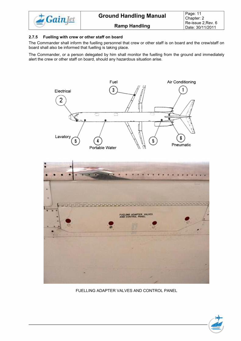
The Commander shall inform the fuelling personnel that crew or other staff is on board and the crew/staff on board shall also be informed that fuelling is taking place.
The Commander, or a person delegated by him shall monitor the fuelling from the ground and immediately alert the crew or other staff on board, should any hazardous situation arise.
When passengers are to be allowed to embark, disembark or remain on board during refuelling or defuelling, the following additional precautions are to be observed:
• Air traffic control and the aerodrome fire services are to be advised that refuelling/defuelling will be taking place with passengers on board;
• Crew, staff and passengers are to be advised that refuelling/defuelling is about to take place and
In the presence of a fire vehicle.
• "Fasten Seat Belt" signs must be off, "No Smoking" signs must be on together with interior lighting to enable emergency exits to be identified;
• Passengers are to be briefed not to smoke at any time on the ground and to remain seated, but with seat belts/harnesses unfastened, until the refuelling has been completed;
• A crew member is to be stationed at the main exit door to assist in the evacuation if an emergency should occur and other emergency door exits must be guarded by cabin crew members who must be prepared for an immediate emergency evacuation;
• If the presence of fuel vapour is detected inside the aeroplane, or any other hazard arises refuelling/defuelling must be stopped immediately;
• No individual items of electrical equipment may be switched on or off while refuelling/defuelling is in progress;
• The position of the fuel bowser/installation relative to the aeroplane is to be such that it will not impede the rapid exit of passengers if an emergency evacuation becomes necessary;
• However notwithstanding the foregoing an operator shall ensure that no aeroplane is re/defuelled with Avgas or widecut fuel (e.g. Jet B or equivalent) or when a mixture of these types of fuel might occur, when passengers are embarking, on board or disembarking.
The emergency fuel cut-off must be pressed in any fuel spillage. In case of a fuel spillage:
• Immediately initiate a removal or dry up of spilled fuel according to local aerodrome regulations
• Inform the Commander
• Inform the Station or the Duty manager
• Inform Operations Control
• Spilled fuel must be removed or dried up before passengers are boarding
• If passengers are on board,they shall ,under appropriate supervision by crew and ground staff,leave the aeroplane.
• Once the details of a spillage have been ascertained,the Manager/Deputy and/or Responsible Person of affected area is responsible for following this procedure:
Chemical or Oil Spillages
1. If the spillage is of a size and nature that could cause danger to the environment and personnel,
Inform the Emergency Services.Ensure that the following information is available before contacting
the Emergency Services.:
• Exact Location of the spill
• Estimated size of the spill
• Name of the company (ies) involved
• Origin of the spill
• Date and time that the spill occurred
• Any other info to enable them to deal with the spill,e.g. Material Safety Data Sheets.
2. If the spillage is small and contained,initiate in-house containment procedure using Emergency
Containment Kit,taking into account the following procedure:
• Ensure that electrical power is switched off at the main isolator panel,before any unplugging.
• Ensure that the area is cordoned off, and that work in the area has stopped.
• Ensure that fire extinguishers are available and placed adjacent to the spill area.
• Ensure that any vehicles within 20 feet are switched off.
• If required,use absorbent materials in order to stop spillage entering drains and waterways.
Also use non-sparking equipment to clean spillage,i.e.plastic shovels,ribber scrapers,etc.,
Available from Toolstores
NOTE: If any spilled product reaches drains and waterways inform the Health and Safety
Department,who in turn will,inform the Airport Authority,National Rivers Authority
and HSE immediately
• All materials used for clean-up must be disposed of in correctly identified waste bin,
then the bins to be stores in a bonded area .Then contact the H & S department to
• If a fuel bowser or Aircraft fuel tank in involved ,ensure the flow of fuel has been stopped,
then arrange for the immediate area to be evacuated
• If the spillage cannot be dealt with initially within 10 minutes,the Emergency Services must
be contacted. If this is the case follow the procedure in (1) of above.
• If the spillage can be dealt with initially within 10 minutes follw the procedure in (2) above.
2.8 Cleaning of aircraft interior
The handling agent is responsible for punctual disposition of cleaning staff and equipment as well as for the proper cleaning on transit and turn-around flights.
Aircraft cleaning must be finished and cleaning staff must have left the aircraft before passengers are boarded.
If passengers remain on board during short transit stops, cabin cleaning must be performed in such a way that the passengers are not disturbed. Cleaning is not allowed during fuelling procedures if passengers are onboard.
2.9 Catering and other pantry suppliers
It is Gain Jet’ objective to only use suppliers approved by the Civil Aviation Authority along the standards and recommendations laid down in Annex 17 to the Chicago Convention and ECAC Document 30.
If the supplier does not meet those criteria, a written contract shall be compel the supplier to:
• Nominate a security responsible person in the company
• Meet the standards and recommendations laid down in Annex 17 to the Chicago Convention and ECAC Document 30
• Establish training requirements for staff concerned along Gain Jet’s security programme
• A random check of the goods supplied shall be made or, if the supplies are sealed, check that the seals are unbroken.
2.10 Potable Water
2.10.1 General Drinking water for GainJet aeroplane shall only be uplifted at stations where the drinking water is bacteriological safe and in its taste satisfactory.
The station engineer or the ramp agent respectively is responsible for the supervision of the water uplift according to local precautions and procedures.
2.10.2 Procedures and responsibilities The quantity of potable water uplift is predefined according each aeroplane type. In any case the senior cabin crew member is responsible for the pre selection of water uplift.
If the cabin crew is not yet on board a station engineer or a ramp agent is responsible for pre-selecting the water uplift according to predefined standards.
2.11.1 General Toilet service is to be performed in every turn-around. The senior cabin crew member or the ramp agent are responsible for the supervision of the toilet service. Approval of the senior cabin crew member should be taken before living the aeroplane.
2.11.2 Procedures
• Empty and flash the wastewater tanks twice.
• Refill the toilet water tanks with the needed quantity twice.
2.12 Departure Activities
All necessary handling activities shall be performed within the time available before departure. The handling agent is responsible for determining when boarding call shall be made. The ramp agent will obtain clearance to board the passengers from the cockpit crew or the purser. Load and aircraft clearance documents shall be handed over to the Purser. The weight and balance documents should be handed over to the Commander at least 5 minutes prior to scheduled departure time. After examination by the Commander the original is kept in the cockpit, the first copy to be handed over to Purser while the second copy is kept by the ramp agent and filed together with a slip from the aircraft technical logbook and a copy of the fuelling order.
Notification to Commander (NOTOC) shall, where applicable, be handed over to the Commander well in advance i.e. at check-in or, if transit or turn-around flight, immediately after landing so that the Commander can initiate or personally perform necessary activities related to such NOTOC.
A final report shall be given to the Commander. Prior to the final report it must be checked that the entries in the weight and balance documents corresponds with the actual loading status of the aircraft.
In case differences (LMC – Last Minute Changes) are found between the actual loading status and the figures used in the mass & balance documents, the changes have to be reported to the Commander.
Note: Differences in fuel may never be registered as LMC.
Before closing the compartment doors it must be ensured that the load is properly secured according to company regulations.
Before initiation of any removal concerning any ground vehicle that could be attached by cable or other attachment with the aircraft ,it is essential that a visual check will take place by the ground vehicle handler, In order to ensure that the vehicle hes correctly been detached from the aircraft and can securely mover away from the aircraft’s service site.
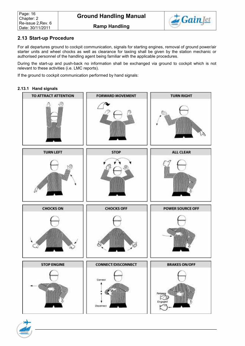
For all departures ground to cockpit communication, signals for starting engines, removal of ground power/air starter units and wheel chocks as well as clearance for taxiing shall be given by the station mechanic or authorised personnel of the handling agent being familiar with the applicable procedures.
During the start-up and push-back no information shall be exchanged via ground to cockpit which is not relevant to these activities (i.e. LMC reports).
If the ground to cockpit communication performed by hand signals:
The staff responsible (mechanic, ramp agent or other authorised staff) must ensure that the engine blast and intake areas are free from personnel or equipment before start-up clearance is given.
Following signals for roll-off clearance shall be observed:
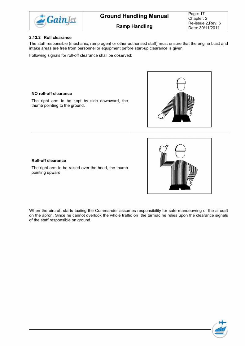
NO roll-off clearance
The right arm to be kept by side downward, the thumb pointing to the ground.
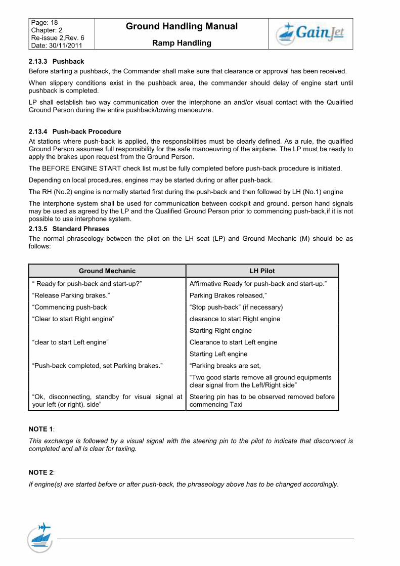
Roll-off clearance
The right arm to be raised over the head, the thumb pointing upward.
When the aircraft starts taxiing the Commander assumes responsibility for safe manoeuvring of the aircraft on the apron. Since he cannot overlook the whole traffic on the tarmac he relies upon the clearance signals of the staff responsible on ground.
Before starting a pushback, the Commander shall make sure that clearance or approval has been received.
When slippery conditions exist in the pushback area, the commander should delay of engine start until pushback is completed.
LP shall establish two way communication over the interphone an and/or visual contact with the Qualified Ground Person during the entire pushback/towing manoeuvre.
2.13.4 Push-back Procedure
At stations where push-back is applied, the responsibilities must be clearly defined. As a rule, the qualified Ground Person assumes full responsibility for the safe manoeuvring of the airplane. The LP must be ready to apply the brakes upon request from the Ground Person.
The BEFORE ENGINE START check list must be fully completed before push-back procedure is initiated.
Depending on local procedures, engines may be started during or after push-back.
The RH (No.2) engine is normally started first during the push-back and then followed by LH (No.1) engine
The interphone system shall be used for communication between cockpit and ground. person hand signals may be used as agreed by the LP and the Qualified Ground Person prior to commencing push-back,if it is not possible to use interphone system.
2.13.5 Standard Phrases
The normal phraseology between the pilot on the LH seat (LP) and Ground Mechanic (M) should be as follows:
Ground Mechanic LH Pilot
“ Ready for push-back and start-up?” Affirmative Ready for push-back and start-up.”
• Never tow the aeroplane while any of its engines are operating.
• Never tow the aeroplane without having someone in the flight compartment to operate the brakes.
• Never tow the aeroplane faster than a slow walk, avoid quick starts and stops.
• Never tow the aeroplane near obstacles without having someone walking at each wing.
• Never allow anyone to enter or leave the aeroplane while it is moving, ensure that all the doors are closed.
• Never allow persons to stand in or near the path of the aeroplane.
• Never remove the chocks until ready to tow the aeroplane. Make sure the person in the flight compartment is ready to operate the brakes.
• Never tow the aeroplane if wind exceeds 30 knots.
• Pull wheel chocks and keep them readily available for use.
• Never tow without gear pins to be found behind Co-pilots seat.
Note: A person in charge must be in a position to observe towing operation!
2.14 Loading
2.14.1 General Aircraft loading is probably the most important function for which one authorised staff of Ground Handling Department is responsible.
Proper loading is important for several different reasons, of which the first and foremost is flight safety.
The goods must be properly secured to prevent shifting while the aircraft is in flight.
The cargo must be inspected and properly distributed to avoid concentrated weight loads which may damage the aircraft floor structure. It is also important that the aircraft is not damaged by ground equipment while the loading is taking place.
Correct loading is also important to efficient and economical operation.
Goods should be segregated in a manner that will allow for expeditious handling at en-route and destination stations.
To the same token, proper loading leads to savings in damage claims.
2.14.2 Loading and unloading
A careful planning of all activities must be made.
• All goods must be inspected for leakage or otherwise damaged shipments.
• All goods must be labelled clearly indicating point of unloading.
• Mail should not be mixed with cargo.
2.14.3 Lashing requirements
All individual items, which by nature, shape or density may constitute a hazard, shall be lashed.
Pieces weighing 330 Lbs or 150 kgs or more, when loaded as bulk in lower compartments should be tied down except when the compartment is volumetrically full. Compartments that are filled up to three-quarters are considered to be volumetrically full.
Particular attention must be given to lashing of Dangerous Goods. In general, all packages containing Dangerous Goods must be stowed in an upright position if so indicated, have the Hazard label visible, and they must be lashed to prevent themselves from shifting or any crushing, tipping or damage by other load.
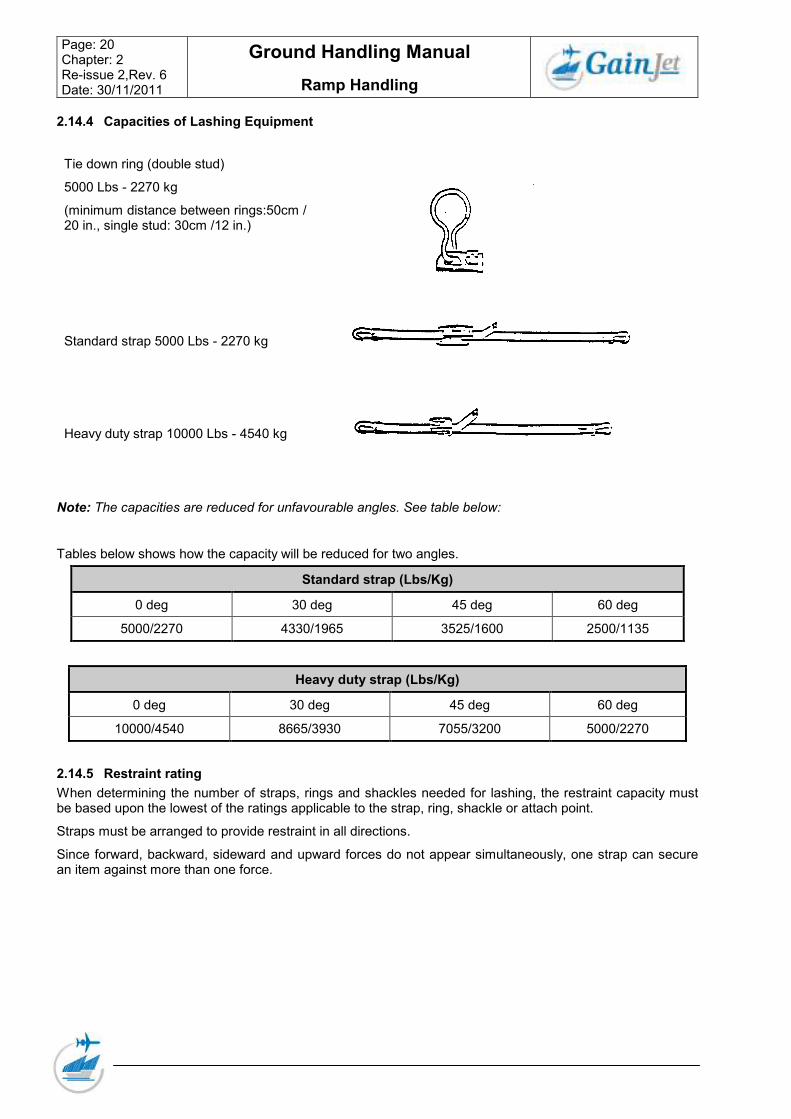
(minimum distance between rings:50cm / 20 in., single stud: 30cm /12 in.)
Standard strap 5000 Lbs - 2270 kg
Heavy duty strap 10000 Lbs - 4540 kg
Note: The capacities are reduced for unfavourable angles. See table below:
Tables below shows how the capacity will be reduced for two angles.
Standard strap (Lbs/Kg)
0 deg 30 deg 45 deg 60 deg
5000/2270 4330/1965 3525/1600 2500/1135
Heavy duty strap (Lbs/Kg)
0 deg 30 deg 45 deg 60 deg
10000/4540 8665/3930 7055/3200 5000/2270
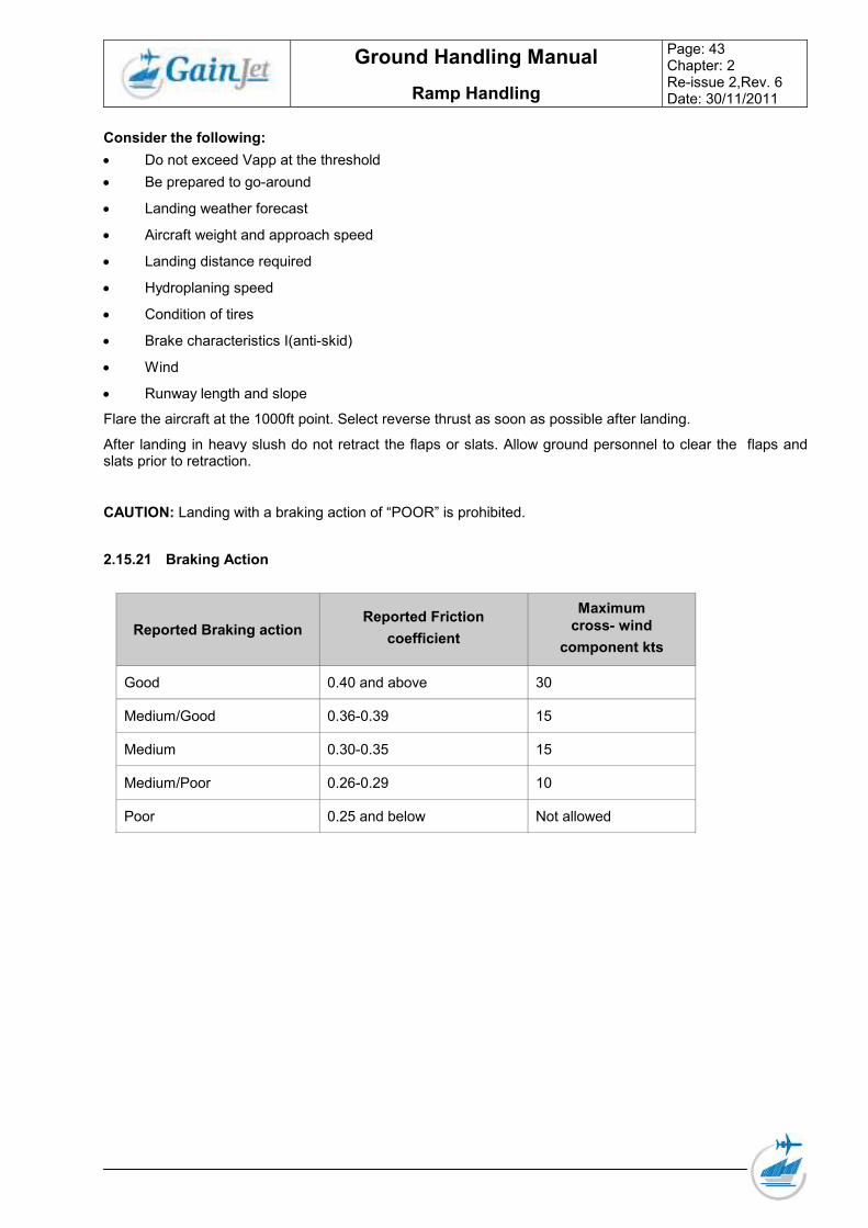
2.14.5 Restraint rating
When determining the number of straps, rings and shackles needed for lashing, the restraint capacity must be based upon the lowest of the ratings applicable to the strap, ring, shackle or attach point.
Straps must be arranged to provide restraint in all directions.
Since forward, backward, sideward and upward forces do not appear simultaneously, one strap can secure an item against more than one force.
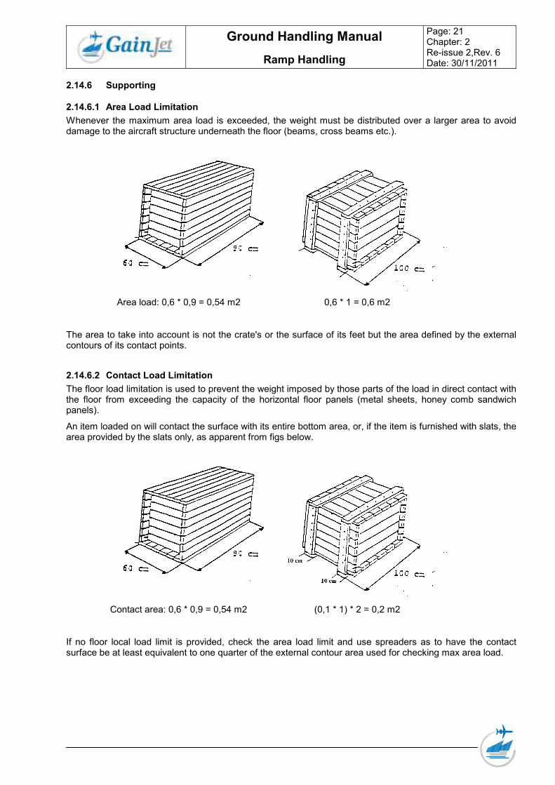
Whenever the maximum area load is exceeded, the weight must be distributed over a larger area to avoid damage to the aircraft structure underneath the floor (beams, cross beams etc.).
Area load: 0,6 * 0,9 = 0,54 m2 0,6 * 1 = 0,6 m2
The area to take into account is not the crate's or the surface of its feet but the area defined by the external contours of its contact points.
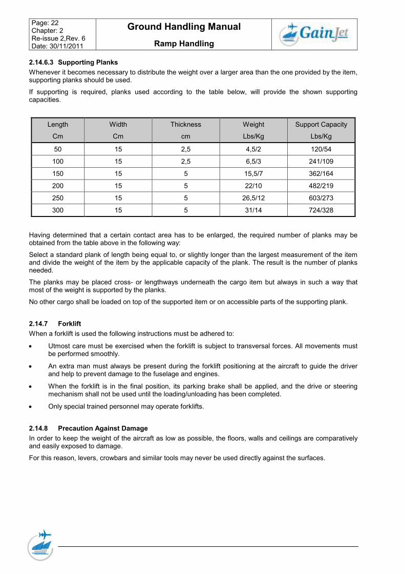
2.14.6.2 Contact Load Limitation
The floor load limitation is used to prevent the weight imposed by those parts of the load in direct contact with the floor from exceeding the capacity of the horizontal floor panels (metal sheets, honey comb sandwich panels).
An item loaded on will contact the surface with its entire bottom area, or, if the item is furnished with slats, the area provided by the slats only, as apparent from figs below.
If no floor local load limit is provided, check the area load limit and use spreaders as to have the contact surface be at least equivalent to one quarter of the external contour area used for checking max area load.
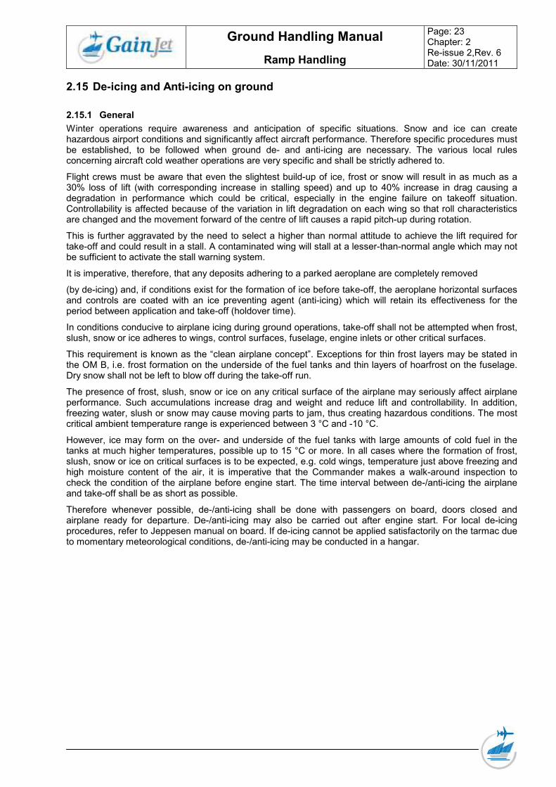
Whenever it becomes necessary to distribute the weight over a larger area than the one provided by the item, supporting planks should be used.
If supporting is required, planks used according to the table below, will provide the shown supporting capacities.
Length
Cm
Width
Cm
Thickness
cm
Weight
Lbs/Kg
Support Capacity
Lbs/Kg
50 15 2,5 4,5/2 120/54
100 15 2,5 6,5/3 241/109
150 15 5 15,5/7 362/164
200 15 5 22/10 482/219
250 15 5 26,5/12 603/273
300 15 5 31/14 724/328
Having determined that a certain contact area has to be enlarged, the required number of planks may be obtained from the table above in the following way:
Select a standard plank of length being equal to, or slightly longer than the largest measurement of the item and divide the weight of the item by the applicable capacity of the plank. The result is the number of planks needed.
The planks may be placed cross- or lengthways underneath the cargo item but always in such a way that most of the weight is supported by the planks.
No other cargo shall be loaded on top of the supported item or on accessible parts of the supporting plank.
2.14.7 Forklift
When a forklift is used the following instructions must be adhered to:
• Utmost care must be exercised when the forklift is subject to transversal forces. All movements must be performed smoothly.
• An extra man must always be present during the forklift positioning at the aircraft to guide the driver and help to prevent damage to the fuselage and engines.
• When the forklift is in the final position, its parking brake shall be applied, and the drive or steering mechanism shall not be used until the loading/unloading has been completed.
• Only special trained personnel may operate forklifts.
2.14.8 Precaution Against Damage
In order to keep the weight of the aircraft as low as possible, the floors, walls and ceilings are comparatively and easily exposed to damage.
For this reason, levers, crowbars and similar tools may never be used directly against the surfaces.
Winter operations require awareness and anticipation of specific situations. Snow and ice can create hazardous airport conditions and significantly affect aircraft performance. Therefore specific procedures must be established, to be followed when ground de- and anti-icing are necessary. The various local rules concerning aircraft cold weather operations are very specific and shall be strictly adhered to.
Flight crews must be aware that even the slightest build-up of ice, frost or snow will result in as much as a 30% loss of lift (with corresponding increase in stalling speed) and up to 40% increase in drag causing a degradation in performance which could be critical, especially in the engine failure on takeoff situation. Controllability is affected because of the variation in lift degradation on each wing so that roll characteristics are changed and the movement forward of the centre of lift causes a rapid pitch-up during rotation.
This is further aggravated by the need to select a higher than normal attitude to achieve the lift required for take-off and could result in a stall. A contaminated wing will stall at a lesser-than-normal angle which may not be sufficient to activate the stall warning system.
It is imperative, therefore, that any deposits adhering to a parked aeroplane are completely removed
(by de-icing) and, if conditions exist for the formation of ice before take-off, the aeroplane horizontal surfaces and controls are coated with an ice preventing agent (anti-icing) which will retain its effectiveness for the period between application and take-off (holdover time).
In conditions conducive to airplane icing during ground operations, take-off shall not be attempted when frost, slush, snow or ice adheres to wings, control surfaces, fuselage, engine inlets or other critical surfaces.
This requirement is known as the “clean airplane concept”. Exceptions for thin frost layers may be stated in the OM B, i.e. frost formation on the underside of the fuel tanks and thin layers of hoarfrost on the fuselage. Dry snow shall not be left to blow off during the take-off run.
The presence of frost, slush, snow or ice on any critical surface of the airplane may seriously affect airplane performance. Such accumulations increase drag and weight and reduce lift and controllability. In addition, freezing water, slush or snow may cause moving parts to jam, thus creating hazardous conditions. The most critical ambient temperature range is experienced between 3 °C and -10 °C.
However, ice may form on the over- and underside of the fuel tanks with large amounts of cold fuel in the tanks at much higher temperatures, possible up to 15 °C or more. In all cases where the formation of frost, slush, snow or ice on critical surfaces is to be expected, e.g. cold wings, temperature just above freezing and high moisture content of the air, it is imperative that the Commander makes a walk-around inspection to check the condition of the airplane before engine start. The time interval between de-/anti-icing the airplane and take-off shall be as short as possible.
Therefore whenever possible, de-/anti-icing shall be done with passengers on board, doors closed and airplane ready for departure. De-/anti-icing may also be carried out after engine start. For local de-icing procedures, refer to Jeppesen manual on board. If de-icing cannot be applied satisfactorily on the tarmac due to momentary meteorological conditions, de-/anti-icing may be conducted in a hangar.
• Active frost Active frost is a condition when frost is forming. This occurs when aircraft surface temperature is At or below 0°C and at or below dew point
• Adhering to A substance is adhering to an airplane when the forces required to remove the substance are greater than those estimated during takeoff.
• Anti Icing A precautionary procedure that provides protection against (for a limited period of time (Hold-Over-Time)). the formation of frost or ice and accumulation of snow or slush of the surfaces of the aeroplane.
• Cold-soak effect The wings of an aircraft are said to be “cold-soaked” when they contain very cold fuel as a result of having just landed after a flight at high altitude or from having been re-fuelled with very cold fuel. Whenever precipitation
falls on a cold-soaked aeroplane when on the ground, clear icing may occur. Even in ambient temperatures
between -2 °C and +15 °C, ice or frost can form in the presence of visible moisture or high humidity if the aircraft structure remains at 0 °C or below. Clear ice is very difficult to be detected visually and may break loose during or after take-off. The following factors contribute to cold-soaking:
o temperature and quantity of fuel in fuel cells,
o type and location of fuel cells,
o length of time at high altitude flights,
o temperature of re-fuelled fuel and
o time since re-fuelling
• Cold soaked wings Cold soaked wings means that wing temperatures are at or below 0 °C due to fuel remaining in the wing tanks during ground time and subsequent re-fuelling is insufficient to cause a significant increase in fuel temperature.
• Clear ice Clear ice is a layer of transparent ice. Clear ice can form when the aeroplane has been or is exposed to high humidity, rain, drizzle or fog and the temperature of the wing surface is slightly above or below 0 °C due to cold soaked wings. The essential area on the aeroplane is the upper surface of the wing. Clear ice may form even if the OAT is 15 °C or more.
Note: Clear Ice can be very difficult to detect and in some situations its presence can only be detected by touch.
• Contamination All forms of frozen or semi frozen moisture, such as snow, slush or ice.
• Contamination check Check of aeroplane surfaces for contamination, to determine the need for de/anti-icing.
• Critical surfaces Critical surfaces include the wings, leading edges, horizontal and vertical stabilizers, ailerons, rudder(s), elevators, spoilers, slats, flaps, fuselage, engine nacelles and inlets. These surfaces must be completely free of frost, slush, snow or ice prior to take-off. Furthermore, pitot tubes, static ports and angle of attack sensors must be free of any contamination.
• De-icing De-icing is a procedure by which frost, slush snow or ice are removed from an airplane in order to provide clean surfaces.
• De-/anti-icing fluids The basic function of de-/anti-icing fluids is to lower the freezing point of water. This delays the accumulation of frost, slush, snow or ice on critical surfaces and/or melts contaminations already present. There are three principal classes of anti-icing fluids, known as ISO/SAE Type I, Type II and Type IV fluids. Type 1½ and Type 3 which are also available are not covered by any international specification and are therefore not approved by Gain Jet.
• Dry snow Fine, powder like snow which does not stick and may be blown or brushed away.
• Freezing conditions Conditions in which the outside air temperature is below +3 °C (37.4 °F) and visible moisture in any form (such as fog with visibility below 1.5 km, rain, snow, sleet or ice crystals) or standing water, slush, ice or snow is present on the runway.
• Freezing drizzle Fairly uniform precipitation composed exclusively of fine drops (diameter less than 0.5 mm [0.02 in]) very close together which freezes upon impact with the ground or other exposed objects.
• Freezing fog Freezing fog is a suspension of numerous minute water droplets which freeze upon impact with ground or other exposed objects, generally reducing the horizontal visibility at the earth’s surface to less than 1 km.
• Freezing rain or freezing drizzle Freezing rain or freezing drizzle consist of super-cooled water droplets with a temperature below 0 XC which will freeze immediately on impact with any solid object. Freezing drizzle is freezing precipitation as above, composed of droplets with a diameter generally of less than 0,5 mm. Freezing rain is freezing precipitation as above, composed of droplets with a diameter generally more than 0,5 mm. If reported light, this means light intensity (subjectively assessed) of the above-mentioned phenomenon.
• Frost/Hoar Frost Frost is a crystallized deposit formed from water vapour on surfaces at or below 0 °C. Forms mostly on cold clear nights by sublimation on surfaces which have a lower temperature than the surrounding air. Such deposits although very thin can seriously affect the aircraft performance. Frost 3 mm or less on the lower surface of the wing has no effect and may be discounted.
• Hail Precipitation of small balls or pieces of ice.
• Holdover time (HOT) Estimated time for which an anti-icing fluid will prevent the formation of frost or ice and the accumulation of snow on the protected surfaces. The protection time is dependant upon weather conditions and fluid mixture and cannot be precisely predetermined for each application.
• Ice pellets Precipitation of transparent (grains of ice) or translucent (small hail) pellets of ice. These pellets usually bounce when hitting a hard surface.
• Light freezing rain Precipitation of liquid water particles which freezes upon impact with exposed objects, either in the form of drops of more than 0.5 mm (0.02 in) or smaller drops which, in contrast to drizzle, are widely separated. Measured intensity of liquid water particles are up to 2.5 mm (0.10 in)/hour or 25 grams/dm2/hour with a maximum of 0.25 mm (0.01 in) in 6 minutes.
• Lowest Operational Use Temperature (LOUT) - The lowest temperature at which a fluid has been tested and certified as acceptable in accordance with the appropriate aerodynamic acceptance test while still maintaining the 7 °C - freezing point temperature buffer
• Moderate and Heavy freezing rain Precipitation of liquid water particles which freezes upon impact with the ground or other exposed objects, either in the form of drops of more than 0.5 mm (0.02 inch) or smaller drops which, in contrast to drizzle, are widely separated. Measured intensity of liquid water particles is more than 2.5 mm/hour (0.10 inch/hour) or 25 grms / dm2 /hour.
• Potential icing Potential icing exists if the outside air temperature (OAT) is below 6 °C and either the difference between OAT and dew point temperature is less than 3 °C or visible moisture exists in any form (fog, rain, rain and snow mixed, drizzle, ice crystals) or standing water, slush, ice or snow are present on the runway.
• Pre-Take off Check A check to assess whether the applied holdover time is still appropriate. This check is normally performed from inside the flight-deck.
• Pre-Take off Contamination Check A check of the critical surfaces for contamination. This check will be performed when the condition of the critical surfaces of the aeroplane cannot be effectively assessed by a pre-take-off check or when the applied holdover time has been exceeded or if there is any doubt regarding the affectivity of anti-icing. This check is normally accomplished from outside the aircraft just before commencing take off roll.
• Rain and Snow (sleet) Precipitation in the form of mixture of rain and snow. For operations in light rain and snow treat as light freezing rain.
• Rime ice An opaque white or milky deposit formed by the rapid freezing of super cooled water droplets, trapping air between them. Rime ice can form on any part of the aircraft and can become very thick on the windward side.
• Slush Snow or ice that has been reduced to a soft water mix by rain, warm temperature and or chemical treatment.
• Snow Precipitation of ice crystals, most of which are branched, star-shaped or mixed with unbranched crystals. At temperatures higher than -5 °C (23 °F), the crystals are generally agglomerated into snowflakes
• Snow Grains Precipitation of very small white and opaque particles of ice that are fairly flat or elongated with a diameter of less than 1 mm (0.04. in.). When snow grains hit hard ground, they do not bounce or shatter.
Note: For holdover time purposes treat snow grains as snow.
• Snow Pellets Precipitation of white, opaque particles of ice. The particles are round or sometimes conical; their diameter range from about 2-5 mm (0.08-0.2 in.). Snow pellets are brittle, easily crushed, they do bounce and may break on hard ground.
• Frost Ice-crystal deposits formed on cold, clear nights by sublimation on surfaces which have a temperature lower than the surrounding air. Such deposits on leading edges and upper surfaces, even when they are very thin (hoar frost) can seriously affect an aeroplane's performance. Frost 3mm or less on the lower surface of a wing has no effect and may be discounted. The OM Part B specifies limits of frost deposits for take-off.
• Dry Snow Fine, powder like snow which does not stick and may be blown or brushed away.
• Wet Snow Has a much higher liquid content and tends to stick on airframe/engine components and may freeze.
• Rime ice An opaque white or milky deposit formed by the rapid freezing of super cooled water droplets, trapping air between them, as they impinge upon an exposed aeroplane. In fog, mist or drizzle conditions with temperature at or below freezing point, rime ice can form on any part of the aeroplane and may become very thick on the windward side.
• Clear ice A coating of ice, generally clear and smooth, but with some air pockets. It is formed on exposed objects at temperatures at, below or slightly above the freezing temperature by freezing of super-cooled drizzle, droplets or raindrops. Since only little air is trapped the result is a clear or glazed appearance.
Crews must be aware of the difficulty of detecting clear ice and, in some situations, its presence may
only be detected by touch. It can also form on aeroplane surfaces below a layer of snow and rime ice.
Significant deposits can form on upper wing surfaces in the vicinity of fuel tanks after refuelling with low temperature fuel or when sufficient super cooled fuel remains in tanks after a long flight at altitude. This has occurred with ambient temperatures as high as 14 °C. Conversely, refuelling with relatively warm fuel can cause dry falling snow to melt with the danger of refreezing on the upper surface of the wing.
When airplane surfaces are contaminated by frost, slush, snow or ice they must be de-iced prior to dispatch. When freezing precipitation exists and there is a risk of precipitation adhering to the surfaces at the time of dispatch, airplane surfaces must be anti-iced. If both, de-icing and anti-icing are required, the procedure may be performed in one or two steps. The selection of one- or two-step processes and/or the mixture ratio depends on weather conditions, equipment and fluid availability and the hold-over-time (HOT) to be achieved.
Heavy accumulations of snow will always be difficult to remove from airplane surfaces and vast quantities of fluid will be consumed. Serious consideration should be given to manual removal of deposits with long soft brooms before normal de-icing with fluids. Prior to de-icing the wings, it must be determined whether or not there is ice under the snow. A layer of snow can hide a sub-layer of clear ice.
Therefore, snow removal is not a guarantee for a completely deiced surface, since the clear ice layer is difficult to see. Deposits of snow should be removed mechanically from engine intakes prior to departure. Any frozen deposit that has bonded to either the lower surface of the intake or the fan blades may be removed by hot air or other means. The application of de-icing fluid in the landing gear and wheel bays must be kept to a minimum. Frozen deposits shall be removed with hot air. To prevent re-freezing, a light spray of Type II/Type IV de-/anti-icing fluid may be applied either by brushing on or with a compression sprayer (garden sprayer).
In some airports, the mixture ratio (de-/anti-icing fluid/water) and the de-icing procedure (one step/two steps) is selected by the de-icing specialist. The Commander usually has no influence on the selection of mixture and de-icing procedures.
Typical concentrations of Type II and Type IV fluids are either 100% or a fluid/water mixture ratio of 75/25% or 50/50%; Type I either 50/50%, 60/40% or 70/30%. Anti-icing fluid may be applied to airplane surfaces on arrival (preferably before unloading begins) short turnarounds, when frost is expected or snow or freezing rain is falling. This will minimize accumulation of frozen precipitation on airplane surfaces prior to departure and often makes subsequent de-icing unnecessary. However, the HOT of the treatment must not be exceeded.
The aeroplane must be treated symmetrically, i.e. the left and the right wings shall both be completely treated, even though only one wing may be contaminated. On designated Types of aeroplanes only the affected area covered with frost above the fuel tanks must be sprayed. However, also in this case both wing areas must be sprayed symmetrically.
An airplane that has been anti-iced with Type II or Type IV fluid shall under no circumstances receive a further coating of anti-ice fluid directly on top of the existing film. If an airplane has to be re-protected
prior to the next flight, the surfaces must first be de-iced with a heated mixture of fluid and water before further application of anti-ice fluid.
When a Type II or Type IV fluid is applied in the second step of a two step procedure and a Type I fluid has been applied in the first step, severe performance degradation results if the two different fluids are not fully compatible. This kind of two-step procedure may only be performed if the combination of fluids is approved by the manufacturer of the Type II or Type IV fluid.
• One-step de-/anti-icing One-step de-/anti-icing means that de-icing and anti-icing are carried out at the same time using a mixture of de-/anti-icing fluid and water. The mixture ratio of de-/anti-icing fluid and water is adjusted to OAT and weather conditions. The de-/anti-icing fluid/water mixture should be applied cold if the Aeroplane surfaces are clean, and hot if the Airplane surfaces are contaminated.
• Two-step de-/anti-icing Two-step de-/anti-icing means that de-icing and anti-icing are carried out in two separate steps. The airplane is first de-iced using either heated water only or a heated mixture of water and de-/anti-icing fluid. After completion of the de-icing operation a film of de-/anti-icing fluid or a mixture of de-/anti-icing fluid and water must be sprayed onto the clean airplane surfaces. The mixture ratio of de-/anti-icing fluid and water is adjusted for OAT and weather conditions.
The second step must be performed before the fluid applied in the first step freezes (typically within three minutes). If necessary the procedure is to be performed area by area. If freezing occurs on anti-iced surfaces these procedures shall be repeated.
After de-icing and/or anti-icing, a Clear Ice Check must be performed on some airplane types to ensure that all frozen precipitation has been removed from the upper wing surface. The Clear Ice Check before, and after de-icing and/or anti-icing, may be delegated to ground or flight personnel, who have been trained and approved to perform the task.
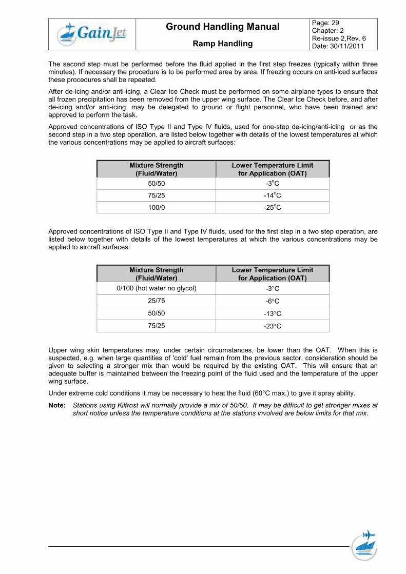
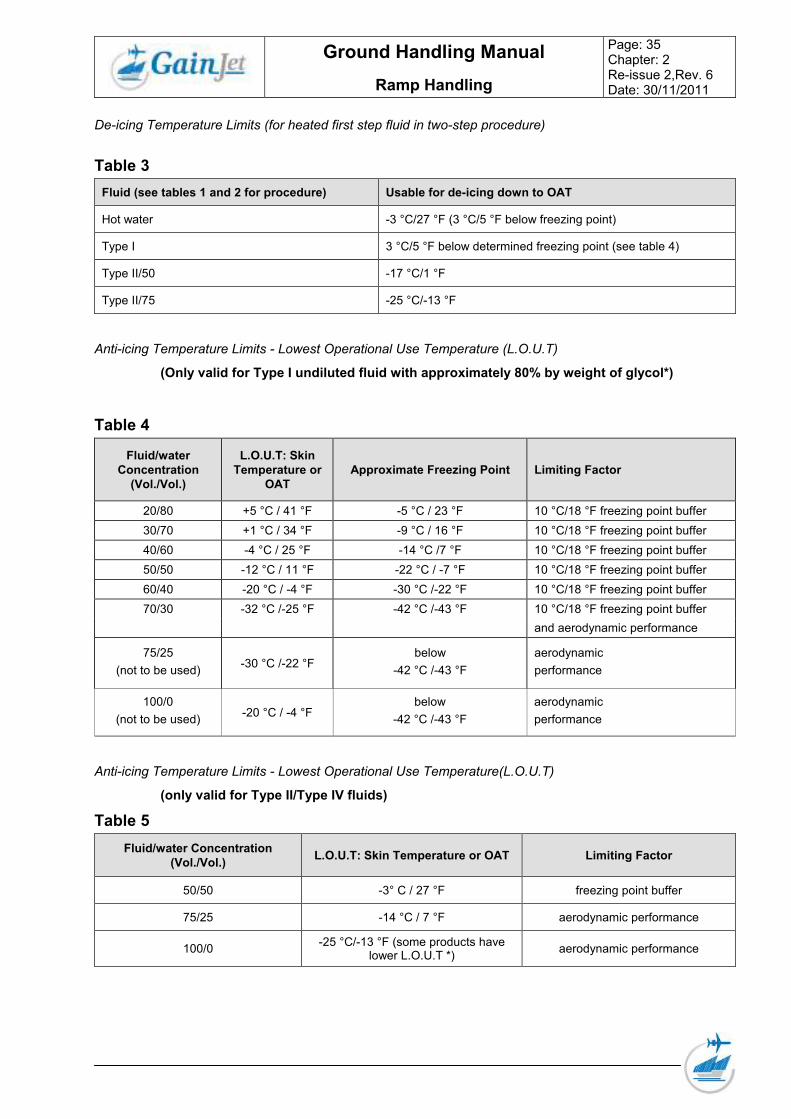
Approved concentrations of ISO Type II and Type IV fluids, used for one-step de-icing/anti-icing or as the second step in a two step operation, are listed below together with details of the lowest temperatures at which the various concentrations may be applied to aircraft surfaces:
Mixture Strength
(Fluid/Water)
Lower Temperature Limit
for Application (OAT)
50/50 -3oC
75/25 -14oC
100/0 -25oC
Approved concentrations of ISO Type II and Type IV fluids, used for the first step in a two step operation, are listed below together with details of the lowest temperatures at which the various concentrations may be applied to aircraft surfaces:
Mixture Strength
(Fluid/Water)
Lower Temperature Limit
for Application (OAT)
0/100 (hot water no glycol) -3°C
25/75 -6°C
50/50 -13°C
75/25 -23°C
Upper wing skin temperatures may, under certain circumstances, be lower than the OAT. When this is suspected, e.g. when large quantities of 'cold' fuel remain from the previous sector, consideration should be given to selecting a stronger mix than would be required by the existing OAT. This will ensure that an adequate buffer is maintained between the freezing point of the fluid used and the temperature of the upper wing surface.
Under extreme cold conditions it may be necessary to heat the fluid (60°C max.) to give it spray ability.
Note: Stations using Kilfrost will normally provide a mix of 50/50. It may be difficult to get stronger mixes at short notice unless the temperature conditions at the stations involved are below limits for that mix.
• Operation in close proximity to other Airplane, equipment and structures;
• Inclination angle, contour and roughness of Airplane surfaces;
• Conditions under which the Airplane was parked (outside, fully or partially in hangar).
The HOT tables show an approximate hold-over-time that could reasonably be expected under varying conditions of precipitation (lower end of the range indicates heavy, the upper end light precipitation).
However, due to the many variables, these times should not be considered as rigid limits, as actual time of protection can be affected by particular conditions existing at the time.
The actual HOT begins when the final application of anti-icing fluid commences and ends when the applied fluid loses its effectiveness. It is left to the Commander’s judgment to determine the HOT at a given concentration, taking into account actual weather conditions.
CAUTION: Due to the many variables that can influence the HOT, the time of protection will be shortened or lengthened depending on the severity of the weather conditions. Heavy precipitation rates or high moisture content, high wind velocity or jet blast may reduce the HOT below the lowest time stated in the range. The HOT may also be reduced when the airplane skin temperature is lower than OAT. Therefore, the indicated times should be used only in conjunction with a pre-take-off check
Aircraft manufacturers normally publish de-icing techniques in their Aircraft Maintenance Manuals.
Other sources of guidance material associated with de-icing are:
• The Association of European Airlines (AEA) "Recommendations for De-Icing/ Anti-Icing of Aircraft on the Ground".
• SAE International "Aircraft De-Icing/ Anti-Icing Methods with Fluids".
• ICAO Doc 9640-AN/940 "Manual of Aircraft Ground De-Icing/Anti-Icing Operations". The Association of European Airlines (AEA) has classified de-icing and anti-icing fluids into three main groups.
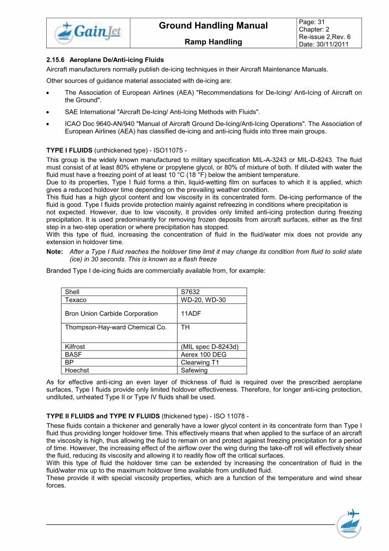
TYPE I FLUIDS (unthickened type) - ISO11075 -
This group is the widely known manufactured to military specification MIL-A-3243 or MIL-D-8243. The fluid must consist of at least 80% ethylene or propylene glycol, or 80% of mixture of both. If diluted with water the fluid must have a freezing point of at least 10 °C (18 °F) below the ambient temperature. Due to its properties, Type I fluid forms a thin, liquid-wetting film on surfaces to which it is applied, which gives a reduced holdover time depending on the prevailing weather condition. This fluid has a high glycol content and low viscosity in its concentrated form. De-icing performance of the fluid is good. Type I fluids provide protection mainly against refreezing in conditions where precipitation is not expected. However, due to low viscosity, it provides only limited anti-icing protection during freezing precipitation. It is used predominantly for removing frozen deposits from aircraft surfaces, either as the first step in a two-step operation or where precipitation has stopped. With this type of fluid, increasing the concentration of fluid in the fluid/water mix does not provide any extension in holdover time.
Note: After a Type I fluid reaches the holdover time limit it may change its condition from fluid to solid state (ice) in 30 seconds. This is known as a flash freeze
Branded Type I de-icing fluids are commercially available from, for example:
Shell S7632
Texaco WD-20, WD-30
Bron Union Carbide Corporation 11ADF
Thompson-Hay-ward Chemical Co. TH
Kilfrost (MIL spec D-8243d)
BASF Aerex 100 DEG
BP Clearwing T1
Hoechst Safewing
As for effective anti-icing an even layer of thickness of fluid is required over the prescribed aeroplane surfaces, Type I fluids provide only limited holdover effectiveness. Therefore, for longer anti-icing protection, undiluted, unheated Type II or Type IV fluids shall be used.
TYPE II FLUIDS and TYPE IV FLUIDS (thickened type) - ISO 11078 -
These fluids contain a thickener and generally have a lower glycol content in its concentrate form than Type I fluid thus providing longer holdover time. This effectively means that when applied to the surface of an aircraft the viscosity is high, thus allowing the fluid to remain on and protect against freezing precipitation for a period of time. However, the increasing effect of the airflow over the wing during the take-off roll will effectively shear the fluid, reducing its viscosity and allowing it to readily flow off the critical surfaces. With this type of fluid the holdover time can be extended by increasing the concentration of fluid in the fluid/water mix up to the maximum holdover time available from undiluted fluid. These provide it with special viscosity properties, which are a function of the temperature and wind shear forces.
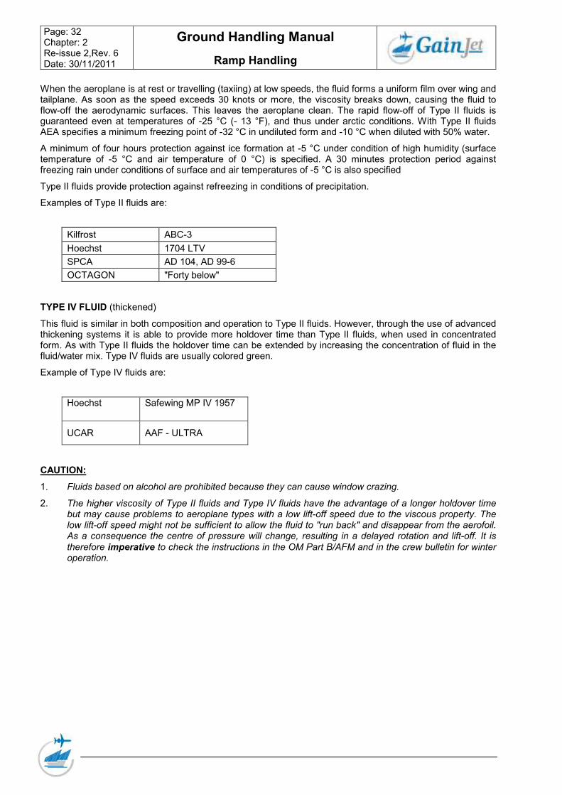
When the aeroplane is at rest or travelling (taxiing) at low speeds, the fluid forms a uniform film over wing and tailplane. As soon as the speed exceeds 30 knots or more, the viscosity breaks down, causing the fluid to flow-off the aerodynamic surfaces. This leaves the aeroplane clean. The rapid flow-off of Type II fluids is guaranteed even at temperatures of -25 °C (- 13 °F), and thus under arctic conditions. With Type II fluids AEA specifies a minimum freezing point of -32 °C in undiluted form and -10 °C when diluted with 50% water.
A minimum of four hours protection against ice formation at -5 °C under condition of high humidity (surface temperature of -5 °C and air temperature of 0 °C) is specified. A 30 minutes protection period against freezing rain under conditions of surface and air temperatures of -5 °C is also specified
Type II fluids provide protection against refreezing in conditions of precipitation.
Examples of Type II fluids are:
Kilfrost ABC-3
Hoechst 1704 LTV
SPCA AD 104, AD 99-6
OCTAGON "Forty below"
TYPE IV FLUID (thickened)
This fluid is similar in both composition and operation to Type II fluids. However, through the use of advanced thickening systems it is able to provide more holdover time than Type II fluids, when used in concentrated form. As with Type II fluids the holdover time can be extended by increasing the concentration of fluid in the fluid/water mix. Type IV fluids are usually colored green.
Example of Type IV fluids are:
Hoechst Safewing MP IV 1957
UCAR AAF - ULTRA
CAUTION:
1. Fluids based on alcohol are prohibited because they can cause window crazing.
2. The higher viscosity of Type II fluids and Type IV fluids have the advantage of a longer holdover time but may cause problems to aeroplane types with a low lift-off speed due to the viscous property. The low lift-off speed might not be sufficient to allow the fluid to "run back" and disappear from the aerofoil. As a consequence the centre of pressure will change, resulting in a delayed rotation and lift-off. It is
therefore imperative to check the instructions in the OM Part B/AFM and in the crew bulletin for winter operation.
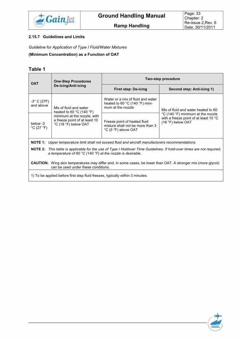
Guideline for Application of Type I Fluid/Water Mixtures
(Minimum Concentration) as a Function of OAT
Table 1
OAT One-Step Procedures
De-icing/Anti-icing
Two-step procedure
First step: De-icing Second step: Anti-icing 1)
-3° C (27F) and above
Mix of fluid and water heated to 60 °C (140 °F) minimum at the nozzle, with a freeze point of at least 10 °C (18 °F) below OAT
Water or a mix of fluid and water heated to 60 °C (140 °F) mini-mum at the nozzle
Mix of fluid and water heated to 60 °C (140 °F) minimum at the nozzle with a freeze point of at least 10 °C (18 °F) below OAT below -3
°C (27 °F)
Freeze point of heated fluid mixture shall not be more than 3 °C (5 °F) above OAT
NOTE 1: Upper temperature limit shall not exceed fluid and aircraft manufacturers recommendations.
NOTE 2: This table is applicable for the use of Type I Holdover Time Guidelines. If hold-over times are not required, a temperature of 60 °C (140 °F) at the nozzle is desirable.
CAUTION: Wing skin temperatures may differ and, in some cases, be lower than OAT. A stronger mix (more glycol) can be used under these conditions.
1) To be applied before first step fluid freezes, typically within 3 minutes.
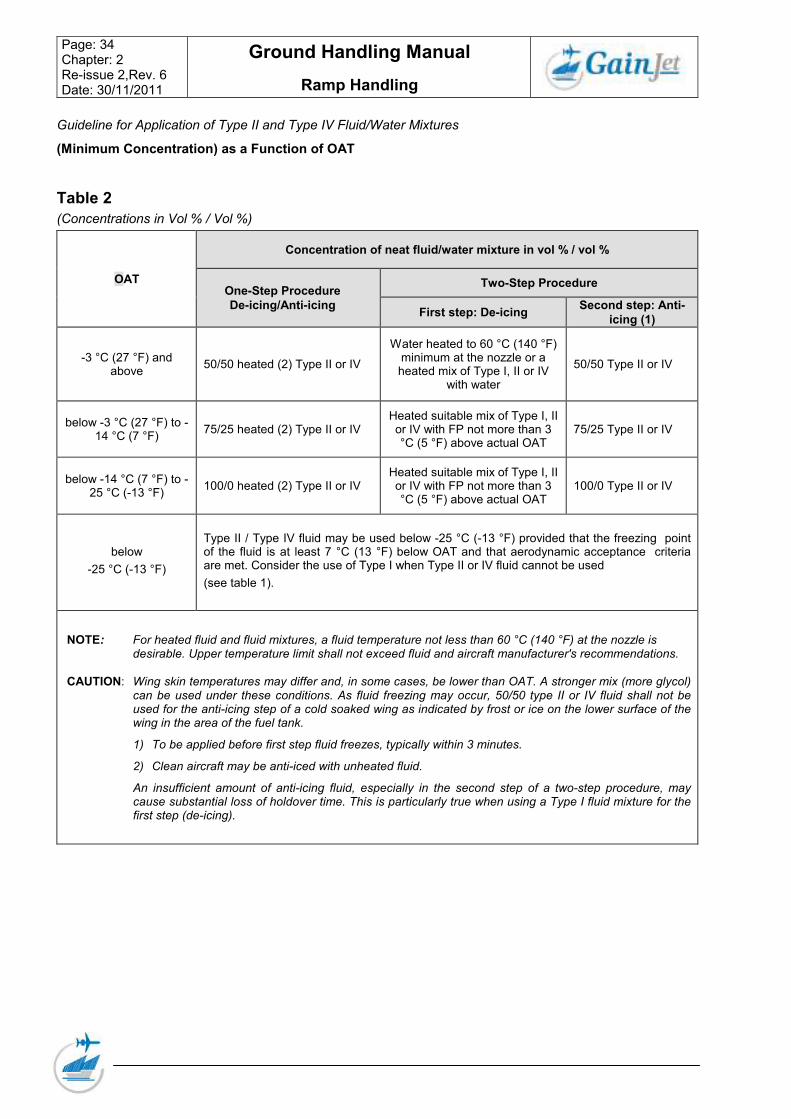
Guideline for Application of Type II and Type IV Fluid/Water Mixtures
(Minimum Concentration) as a Function of OAT
Table 2
(Concentrations in Vol % / Vol %)
OAT
Concentration of neat fluid/water mixture in vol % / vol %
One-Step Procedure
De-icing/Anti-icing
Two-Step Procedure
First step: De-icing Second step: Anti-
icing (1)
-3 °C (27 °F) and above
50/50 heated (2) Type II or IV
Water heated to 60 °C (140 °F) minimum at the nozzle or a heated mix of Type I, II or IV
with water
50/50 Type II or IV
below -3 °C (27 °F) to -14 °C (7 °F)
75/25 heated (2) Type II or IV Heated suitable mix of Type I, II or IV with FP not more than 3 °C (5 °F) above actual OAT
75/25 Type II or IV
below -14 °C (7 °F) to -25 °C (-13 °F)
100/0 heated (2) Type II or IV Heated suitable mix of Type I, II or IV with FP not more than 3 °C (5 °F) above actual OAT
100/0 Type II or IV
below
-25 °C (-13 °F)
Type II / Type IV fluid may be used below -25 °C (-13 °F) provided that the freezing point of the fluid is at least 7 °C (13 °F) below OAT and that aerodynamic acceptance criteria are met. Consider the use of Type I when Type II or IV fluid cannot be used
(see table 1).
NOTE: For heated fluid and fluid mixtures, a fluid temperature not less than 60 °C (140 °F) at the nozzle is desirable. Upper temperature limit shall not exceed fluid and aircraft manufacturer's recommendations.
CAUTION: Wing skin temperatures may differ and, in some cases, be lower than OAT. A stronger mix (more glycol) can be used under these conditions. As fluid freezing may occur, 50/50 type II or IV fluid shall not be used for the anti-icing step of a cold soaked wing as indicated by frost or ice on the lower surface of the wing in the area of the fuel tank.
1) To be applied before first step fluid freezes, typically within 3 minutes.
2) Clean aircraft may be anti-iced with unheated fluid.
An insufficient amount of anti-icing fluid, especially in the second step of a two-step procedure, may cause substantial loss of holdover time. This is particularly true when using a Type I fluid mixture for the first step (de-icing).
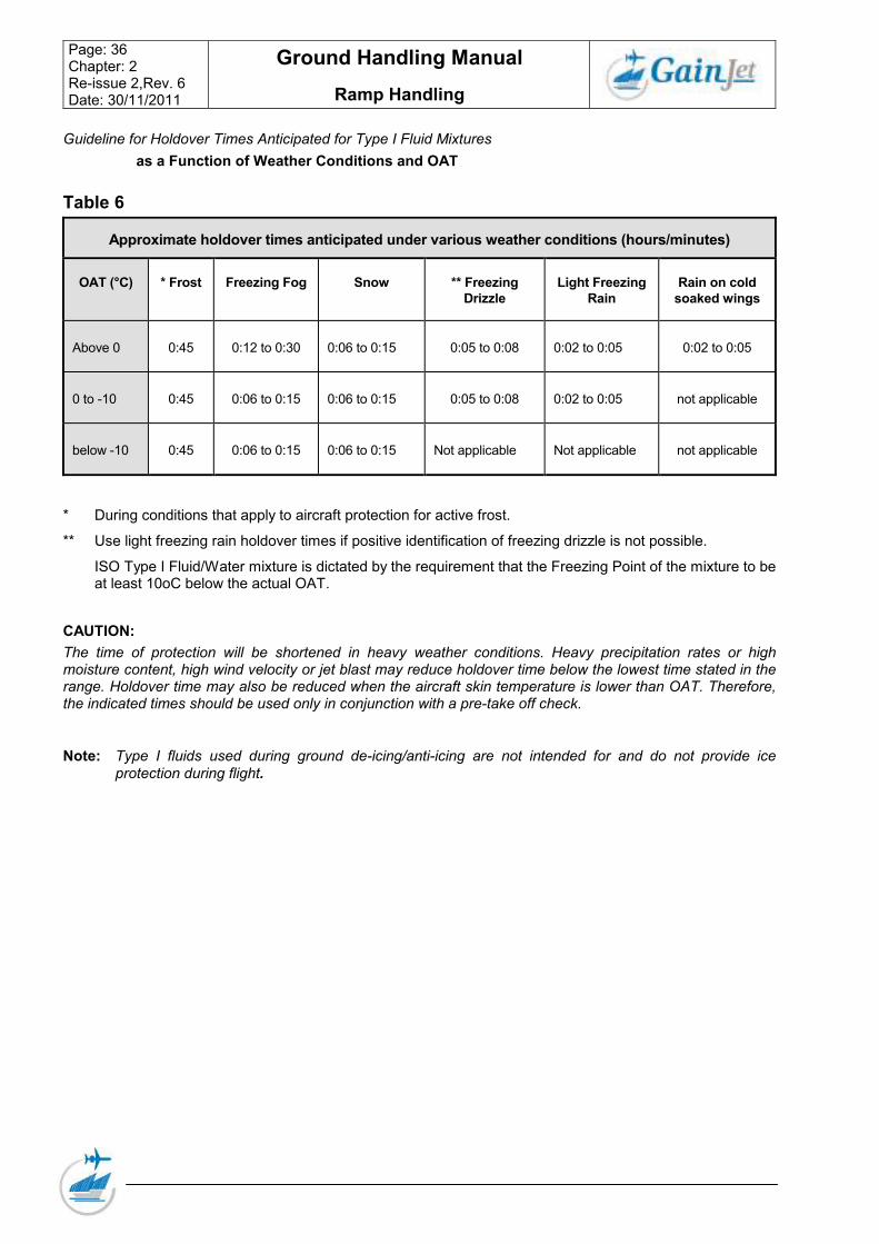
Guideline for Holdover Times Anticipated for Type I Fluid Mixtures
as a Function of Weather Conditions and OAT
Table 6
Approximate holdover times anticipated under various weather conditions (hours/minutes)
OAT (°C) * Frost Freezing Fog Snow ** Freezing
Drizzle
Light Freezing
Rain
Rain on cold
soaked wings
Above 0 0:45 0:12 to 0:30 0:06 to 0:15 0:05 to 0:08 0:02 to 0:05 0:02 to 0:05
0 to -10 0:45 0:06 to 0:15 0:06 to 0:15 0:05 to 0:08 0:02 to 0:05 not applicable
below -10 0:45 0:06 to 0:15 0:06 to 0:15 Not applicable Not applicable not applicable
* During conditions that apply to aircraft protection for active frost.
** Use light freezing rain holdover times if positive identification of freezing drizzle is not possible.
ISO Type I Fluid/Water mixture is dictated by the requirement that the Freezing Point of the mixture to be at least 10oC below the actual OAT.
CAUTION:
The time of protection will be shortened in heavy weather conditions. Heavy precipitation rates or high moisture content, high wind velocity or jet blast may reduce holdover time below the lowest time stated in the range. Holdover time may also be reduced when the aircraft skin temperature is lower than OAT. Therefore, the indicated times should be used only in conjunction with a pre-take off check.
Note: Type I fluids used during ground de-icing/anti-icing are not intended for and do not provide ice
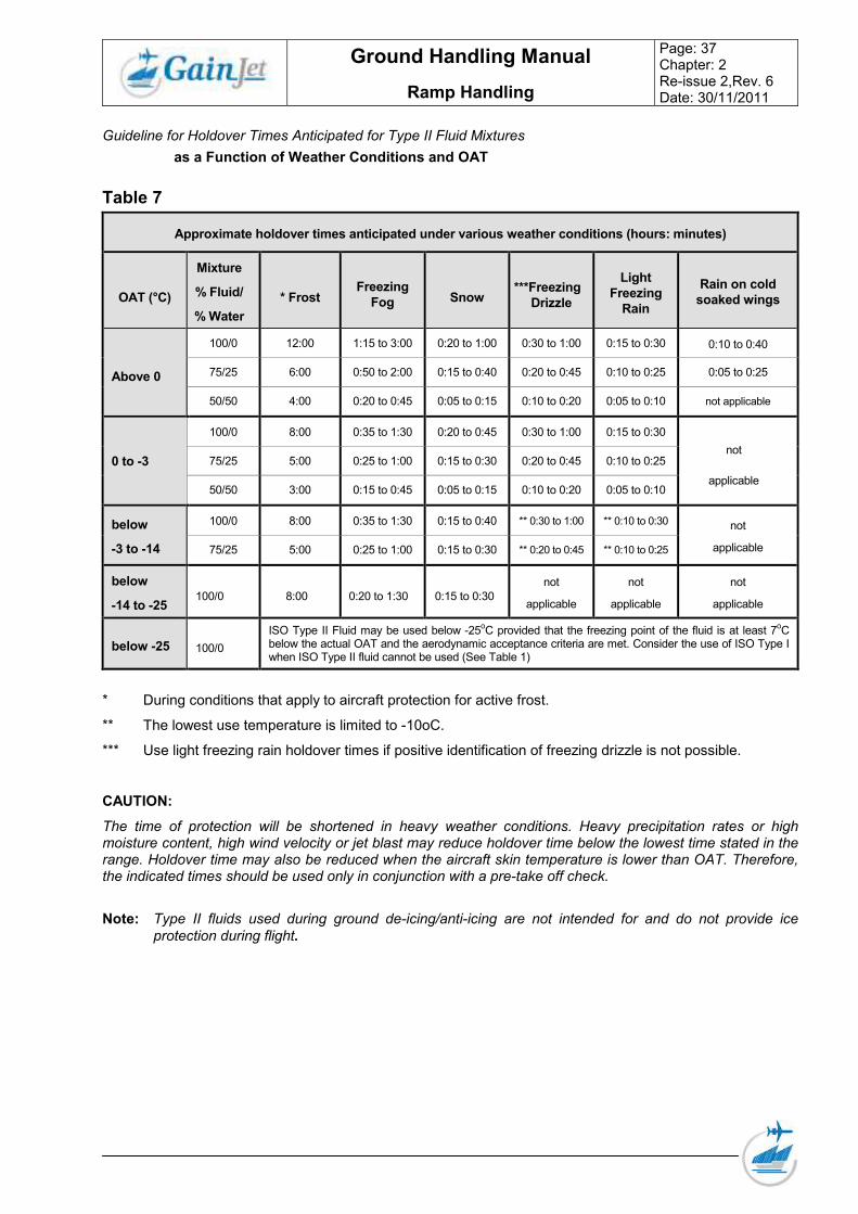
Guideline for Holdover Times Anticipated for Type II Fluid Mixtures
as a Function of Weather Conditions and OAT
Table 7
Approximate holdover times anticipated under various weather conditions (hours: minutes)
OAT (°C)
Mixture
% Fluid/
% Water
* Frost Freezing
Fog Snow ***Freezing
Drizzle
Light
Freezing
Rain
Rain on cold
soaked wings
Above 0
100/0 12:00 1:15 to 3:00 0:20 to 1:00 0:30 to 1:00 0:15 to 0:30 0:10 to 0:40
75/25 6:00 0:50 to 2:00 0:15 to 0:40 0:20 to 0:45 0:10 to 0:25 0:05 to 0:25
50/50 4:00 0:20 to 0:45 0:05 to 0:15 0:10 to 0:20 0:05 to 0:10 not applicable
0 to -3
100/0 8:00 0:35 to 1:30 0:20 to 0:45 0:30 to 1:00 0:15 to 0:30
not
applicable
75/25 5:00 0:25 to 1:00 0:15 to 0:30 0:20 to 0:45 0:10 to 0:25
50/50 3:00 0:15 to 0:45 0:05 to 0:15 0:10 to 0:20 0:05 to 0:10
below
-3 to -14
100/0 8:00 0:35 to 1:30 0:15 to 0:40 ** 0:30 to 1:00 ** 0:10 to 0:30 not
applicable 75/25 5:00 0:25 to 1:00 0:15 to 0:30 ** 0:20 to 0:45 ** 0:10 to 0:25
below
-14 to -25 100/0 8:00 0:20 to 1:30 0:15 to 0:30
not
applicable
not
applicable
not
applicable
below -25 100/0
ISO Type II Fluid may be used below -25oC provided that the freezing point of the fluid is at least 7
oC
below the actual OAT and the aerodynamic acceptance criteria are met. Consider the use of ISO Type I when ISO Type II fluid cannot be used (See Table 1)
* During conditions that apply to aircraft protection for active frost.
** The lowest use temperature is limited to -10oC.
*** Use light freezing rain holdover times if positive identification of freezing drizzle is not possible.
CAUTION:
The time of protection will be shortened in heavy weather conditions. Heavy precipitation rates or high moisture content, high wind velocity or jet blast may reduce holdover time below the lowest time stated in the range. Holdover time may also be reduced when the aircraft skin temperature is lower than OAT. Therefore, the indicated times should be used only in conjunction with a pre-take off check.
Note: Type II fluids used during ground de-icing/anti-icing are not intended for and do not provide ice
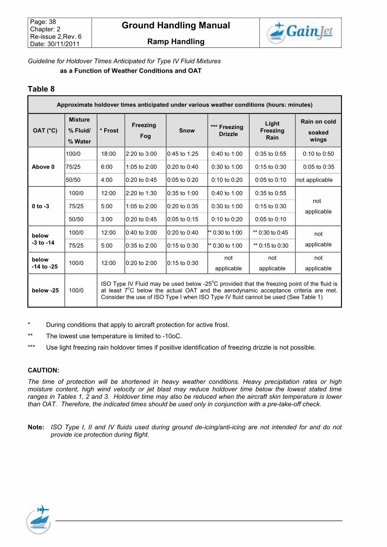
Guideline for Holdover Times Anticipated for Type IV Fluid Mixtures
as a Function of Weather Conditions and OAT
Table 8
Approximate holdover times anticipated under various weather conditions (hours: minutes)
OAT (°C)
Mixture
% Fluid/
% Water
* Frost Freezing
Fog Snow
*** Freezing
Drizzle
Light
Freezing
Rain
Rain on cold
soaked
wings
Above 0
100/0 18:00 2:20 to 3:00 0:45 to 1:25 0:40 to 1:00 0:35 to 0:55 0:10 to 0:50
75/25 6:00 1:05 to 2:00 0:20 to 0:40 0:30 to 1:00 0:15 to 0:30 0:05 to 0:35
50/50 4:00 0:20 to 0:45 0:05 to 0:20 0:10 to 0:20 0:05 to 0:10 not applicable
0 to -3
100/0 12:00 2:20 to 1:30 0:35 to 1:00 0:40 to 1:00 0:35 to 0:55
not
applicable 75/25 5:00 1:05 to 2:00 0:20 to 0:35 0:30 to 1:00 0:15 to 0:30
50/50 3:00 0:20 to 0:45 0:05 to 0:15 0:10 to 0:20 0:05 to 0:10
below
-3 to -14
100/0 12:00 0:40 to 3:00 0:20 to 0:40 ** 0:30 to 1:00 ** 0:30 to 0:45 not
applicable 75/25 5:00 0:35 to 2:00 0:15 to 0:30 ** 0:30 to 1:00 ** 0:15 to 0:30
below
-14 to -25 100/0 12:00 0:20 to 2:00 0:15 to 0:30
not
applicable
not
applicable
not
applicable
below -25 100/0 ISO Type IV Fluid may be used below -25
oC provided that the freezing point of the fluid is
at least 7oC below the actual OAT and the aerodynamic acceptance criteria are met.
Consider the use of ISO Type I when ISO Type IV fluid cannot be used (See Table 1)
* During conditions that apply to aircraft protection for active frost.
** The lowest use temperature is limited to -10oC.
*** Use light freezing rain holdover times if positive identification of freezing drizzle is not possible.
CAUTION:
The time of protection will be shortened in heavy weather conditions. Heavy precipitation rates or high moisture content, high wind velocity or jet blast may reduce holdover time below the lowest stated time ranges in Tables 1, 2 and 3. Holdover time may also be reduced when the aircraft skin temperature is lower than OAT. Therefore, the indicated times should be used only in conjunction with a pre-take-off check.
Note: ISO Type I, II and IV fluids used during ground de-icing/anti-icing are not intended for and do not provide ice protection during flight.
The authority to decide whether de-/anti-icing of the airplane is necessary lies with the Commander. He determines the necessity for removal of frost, slush, snow or ice and orders the de-icing equipment via the handling agent.
The Commander decides which airplane parts have to be de-/anti-iced, e.g. wings only, wings and tail or the complete airplane. He is responsible for calculating the Hold-Over-Time (HOT) based on:
• XHOT tables
• Actual weather conditions;
• Applied type and mixture ratio of de-/anti-icing fluid (ADF).
The decision regarding airplane acceptance after de-/anti-icing treatment rests with the Commander. He takes responsibility for the airworthiness of the airplane after confirmed completion of airplane de-/anti-icing. The commander may not be able personally to check the aircraft for the correct treatment and so in this case the person releasing the aeroplane after de/anti-icing process is responsible for the performance and verification of the results. He will communicate to the commander the time started the procedure and type of fluid/mix used.
Example of the information to the commander:
a. AEA type 2 100/0 0600H 01.09.04
b. AEA type 2 being the brand name of the fluid.
c. 100/0 being the fluid and the water content
d. 0600H being the time the procedure commenced
e. being the date the procedure was carried out
2.15.9 Ground staff Responsibilities
The ground staff is responsible for the correct de-/anti-icing of the aeroplane. This must be performed according to Commander’s instruction and the regulations published in the Gain Jet Ground Handling Manual. The person responsible for the final check after de-icing at all stations it is the station engineer or a person designated by the handling company.
It is the responsibility of the spray operator or the authorized person releasing the airplane that the Commander is correctly informed regarding the performed de-/anti-icing treatment. The communication of the anti-icing code to the flight crew confirms, that the check after de-icing/ anti-icing was completed and the airplane critical parts are free of ice, frost snow and slush.
2.15.10 Handling company Responsibilities
The handling company is responsible for the availability of personnel, equipment and fluids. All actions in connection with de-/anti-icing shall be coordinated with the station engineer and the flight crew. Procedures and fluids deviating from the ISO/SAE standard must be approved by Gain Jet Maintenance department, Athens.
2.15.11 Communication between de-icing crew and the flight deck
Before de-icing
The ground or station engineer, the de-icer or the handling company responsible requests authorisation from the Commander to start de-/anti-icing.
After de-icing
The Commander will be informed verbally of the:
• One-step/two-step procedure applied (on request only);
• Fluid Type (Type I, II or Type );
• Mixture ratio for Types II and IV;
• Starting time of the last step of de-/anti-icing treatment;
• Confirmation that the airplane complies with the “Clean airplane concept”;
Information example
If a mixture of 75% Type II and 25% water were used for the final step of de-/anti-icing operation which commenced at 11.55h (LT), the information to the flight crew would be as follows:
• “Type II, 75/25, 1155, clean Airplane check completed.”
• The time entry in the Airplane technical log, however, shall be made in UTC
2.15.12 Contamination check
The contamination check includes also detection of clear-ice and under-wing frost. The Commander must verify that the contamination check has been conducted by the responsible Ground or Station Engineer. Clear-ice is very difficult to detect visually and may occur well above freezing point. Clear-ice may also occur below a layer of snow or slush. It is therefore important that surfaces will be closely inspected and a hands-on check is made, when there is any doubt whether clear-ice has been formed
2.15.13 Pre de-iced airplane
If an airplane has been pre de-iced , the respective airplane de/anti-icing information will be made available to the Commander and must then be entered into the airplane Technical Log.
2.15.14 Technical log Whenever deicing has taken place on the stand, before taxi-out, the commander must make an entry in the technical log showing the times of start and completion of the procedure. If there is a subsequent departure delay or a deterioration in the weather he will use this information to evaluate whether deicing is again required prior to departure.
2.15.15 Ramp and taxi procedures Icy conditions on the ramp/gate area may mean that the push-back vehicle may not be able to push with the aircraft engines running due to poor traction on a slippery surface. In this case push-back to a position where engines can be started and the taxi commence. Taxiing may be commenced on uncleard surfaces at the discretion of the commander. Be aware that idle thrust may be sufficient to move the aircraft forward even with the park brake set.
Engine nacelle anti-icing should be ON when the OAT is 10C or less and icing conditions exist. Ensure that ALL probes and sensor heating elements are ON before taxiing. Taxi with caution since rutted areas can cause steering problems. Neither aircraft or ground vehicles can stop quickly on slippery surfaces.
Snow may cover the taxiway markings so care must be taken to remain within the taxiiway width. Test brakes and steering – frequently. Maintain a greater distance than normal behind other aircraft in order to avoid blown contamination from re-freezing on the aircraft which may require the aircraft to be de-iced prior to take-off.
Flaps should remain UP when taxiing through snow or slush and selected to the take-off position shortly prior to take-off.
Note: Ensure that probe and sensor heating systems are ON prior to taxi.
2.15.16 Pre-take-off check
The check has to be used in case the HOT has expired or any doubt about the state of the wing surface exists. It ensures that the representative surfaces of the airplane are free of ice, snow, slush or frost just prior to takeoff. The check shall be accomplished by a trained and qualified person as close to the time of takeoff as possible and is normally made from inside the airplane by visually checking the wings or other critical surfaces.
If the check from inside the cabin is not possible (due to soiled windows or insufficient lighting) , the wings must be checked from outside the airplane. If the check is unsatisfactory, de-icing/anti-icing must be repeated.
When any doubt exists as to whether or not any deposit may adversely effect the airplane’s performance and/or controllability the Commander shall not commence takeoff.
Take-off is prohibited if any of the following conditions exist:
• Snow, ice or frost deposits are adhering , to the wings, control surfaces, engines of the aeroplane
• Heavy fall of wet snow ,with ambient temperature around freezing point;
• Freezing rain or freezing drizzle unless adequately protected by anti-ice treatment
• The runway braking action is reported as “poor" (braking coefficient less than 0.25),
Observe appropriate performance limitations for take-off. Acceleration will be adversely affected by slush or standing water on the runway, which cause significantly greater drag. Be alert for conditions which could affect stopping and directional control should it become necessary to abort. Line up carefully and ensure that the nose wheel is straight, as skidding of an offset nose wheel upsets directional control, Apply thrust slowly to prevent asymmetry which would also affect directional control, During take off roll; maintain positive forward pressure on the nose wheel and use rudder for directional control as it becomes effective.
2.15.17 Take-off
• Take-off is prohibited if any of the following conditions exist:
• Snow, ice or frost deposits are adhering to the wings, control surfaces, engines of the aeroplane.
• Heavy fall of wet snow with ambient temperatures around 0C.
• Moderate or heavy freezing rain
• Runway braking action reported as poor.
Acceleration may be slower than normal due to drag caused by slush or standing water. Be aware of conditions that may adversely affect stopping in the event of a rejected take-off.
Large quantities of snow/slush may be thrown into the engine, static ports and airframe during take-off.
Apply thrust slowly and symmetrically in order avoid skidding which may lead to loss of control. During the take-off run maintain slight forward pressure on the control wheel and use the rudder for directional control.
CAUTION
• Take-off on a runway covered with more than 7.5cm of dry snow and 1.25cm wet snow is prohibited
• Take-off with a braking action of “POOR” is prohibited.
Directional control problems may be aggravated during an aborted take-off due to excessive anti-skid cycling and/or individual wheels skidding. The rudder must be used as the primary steering aid and, to regain directional control, be prepared to release wheel brakes, cancel reverse thrust and reselect forward idle. Brakes should be re-applied when directional control is re- gained. Do not "pump" the wheel brakes when the anti-skid system is ON.
2.15.19 Rotation Technique
Despite apparently effective anti-ice treatment, the airplane could become contaminated during the take-off roll. With contamination on the wings, the aircraft will behave as if it were incorrectly trimmed in the nose-up attitude as the angle of attack is increased, requiring an abnormal push force to prevent entry into the stall region. It is critically important that the rotation be performed smoothly at a rate of 2-3 degrees per second and target pitch attitude should not be exceeded. This will ensure that any abnormal pitch-up tendency is detected early and the wing angle of attack does not become higher than normal.
If pitch-up or lateral instability is experienced )after lift-off, use elevator, rudder and aileron to maintain the desired attitude. Apply maxi- mum available thrust and use smooth continuous control inputs to avoid over controlling. Do not allow further increase in pitch attitude until full lateral control has been regained.
Select wing and stabilizer anti-ice systems to ON as soon as practicable after lift-off.
2.15.20 Landing on Contaminated Runways//Braking action
The stopping performance of an aircraft is to a greater degree dependent on the friction between the aircraft tires and the runway surface and the landing speed.
In some cases the runway length required could be critical in relation to the runway length available. To compensate for the reduced stopping and directional control capability for adverse runway conditions, performance corrections are applied:
• Runway length increment
• Reduction on allowable landing weight
• Reduction in allowable cross wind component.
Braking action is reported by the tower (latest report, by the ATIS and by NOTAM as:
• Good
• Medium
• Poor
Pilots should be aware that where rain, hail, sleet or snow showers are encountered on the approach or have been reported as have recently crossed the aerodrome there is a high probability of the runway being contaminated.
Use of reverse thrust on landing on dry snow in very low temperatures will blow the snow forward especially at low speed and may reduce forward visibility considerably. Also the increase of temperature may melt this snow and form clear ice on refreezing on static ports etc.,
The required landing field length for a dry runway is defined as 1.67 times the demonstrated dry landing distances. For wet runways the landing distance requirement is increased by 15%.
Note: Landing on contaminated runways without antiskid should be avoided.