33002439.09 www.schneider-electric.com Grounding and Electromagnetic Compatibility of PLC Systems 33002439 10/2013 Grounding and Electromagnetic Compatibility of PLC Systems Basic Principles and Measures User Manual 10/2013
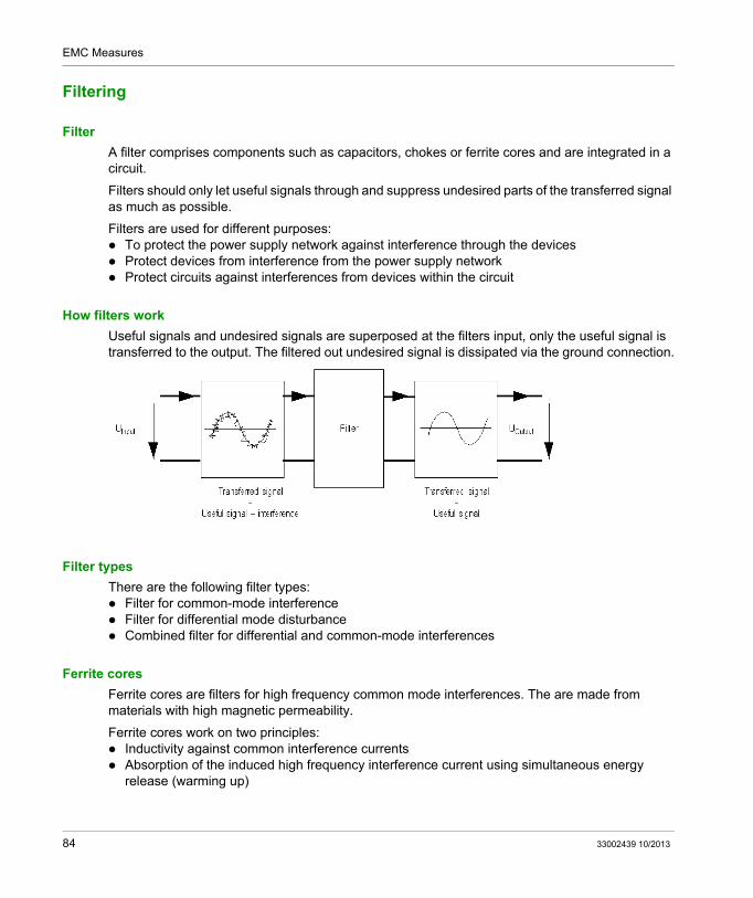
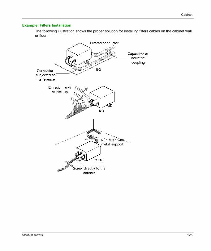
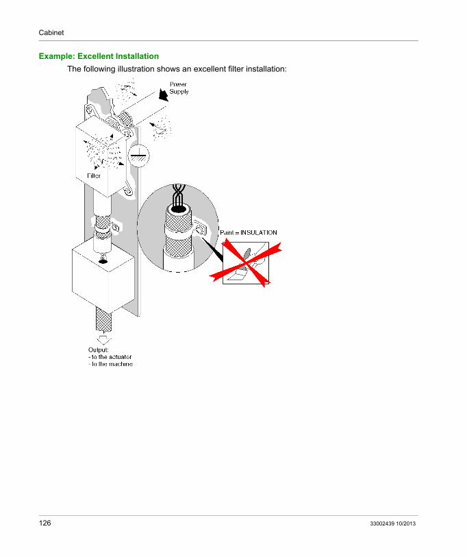
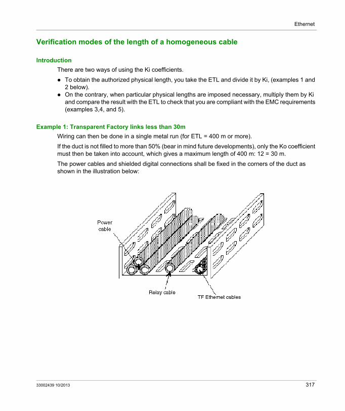
Transcript
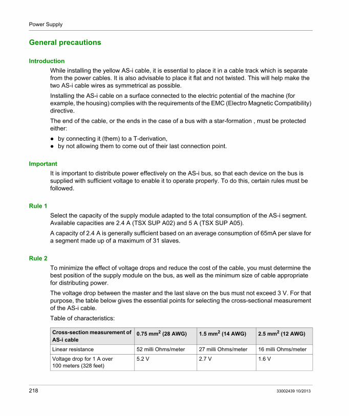
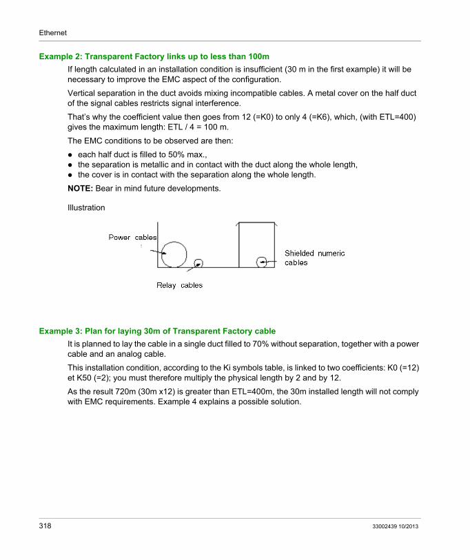
Grounding and Electromagnetic Compatibility of PLC Systems
33002439 10/2013
3300
2439
.09
www.schneider-electric.com
Grounding and Electromagnetic Compatibility of PLC SystemsBasic Principles and MeasuresUser Manual
10/2013
The information provided in this documentation contains general descriptions and/or technical characteristics of the performance of the products contained herein. This documentation is not intended as a substitute for and is not to be used for determining suitability or reliability of these products for specific user applications. It is the duty of any such user or integrator to perform the appropriate and complete risk analysis, evaluation and testing of the products with respect to the relevant specific application or use thereof. Neither Schneider Electric nor any of its affiliates or subsidiaries shall be responsible or liable for misuse of the information contained herein. If you have any suggestions for improvements or amendments or have found errors in this publication, please notify us.
No part of this document may be reproduced in any form or by any means, electronic or mechanical, including photocopying, without express written permission of Schneider Electric.
All pertinent state, regional, and local safety regulations must be observed when installing and using this product. For reasons of safety and to help ensure compliance with documented system data, only the manufacturer should perform repairs to components.
When devices are used for applications with technical safety requirements, the relevant instructions must be followed.
Failure to use Schneider Electric software or approved software with our hardware products may result in injury, harm, or improper operating results.
Failure to observe this information can result in injury or equipment damage.
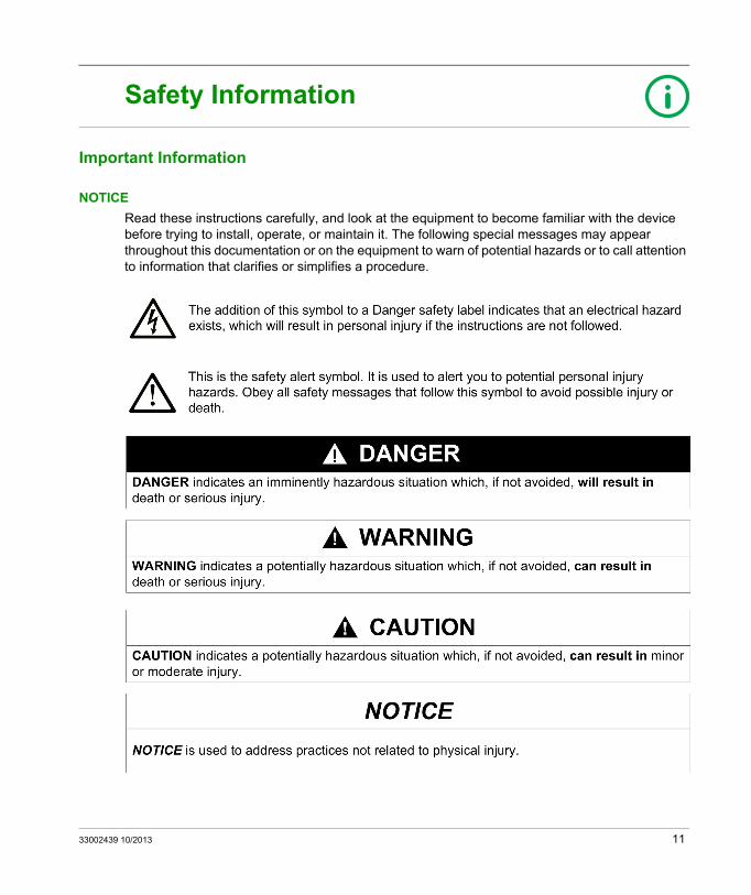
Read these instructions carefully, and look at the equipment to become familiar with the device before trying to install, operate, or maintain it. The following special messages may appear throughout this documentation or on the equipment to warn of potential hazards or to call attention to information that clarifies or simplifies a procedure.
33002439 10/2013 11
PLEASE NOTE
Electrical equipment should be installed, operated, serviced, and maintained only by qualified personnel. No responsibility is assumed by Schneider Electric for any consequences arising out of the use of this material.
A qualified person is one who has skills and knowledge related to the construction and operation of electrical equipment and its installation, and has received safety training to recognize and avoid the hazards involved.
12 33002439 10/2013
About the Book
At a Glance
Document Scope
This manual is intended for users of Schneider Electric PLC systems during configuration and installation and provides information regarding grounding and measures for electromagnetic compatibility (EMC).
This manual serves the following purposes: Provides an overview of general problems regarding grounding and EMC Eases the selection of grounding and EMC measures in the entire system (machine or system) Provides guidelines for configuration and installation of Schneider Electric components
regarding grounding and EMC
Section 1 contains information concerning regulations in the European Union (EU) and in North America. This section also contains references to relevant international standards.
Section 2 contains basic information concerning grounding and electromagnetic disturbances. You will also find information concerning standard EMC measures listed according to the type of measure.
Section 3 contains guidelines for EMC and grounding measures in an automated system listed according to system area.
Sections 4-6 contains special configuration and installation information for the following three Schneider PLC families: Quantum Premium Momentum
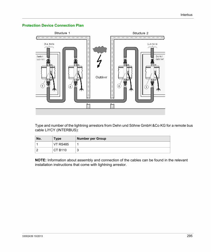
Section 7 contains special configuration and installation information for the following network components: Modbus Plus Remote I/O PROFIBUS INTERBUS Ethernet
Validity Note
This document is valid from Unity Pro 8.0.
33002439 10/2013 13
14 33002439 10/2013
Grounding and Electromagnetic Compatibility of PLC Systems
Regulations and Standards
33002439 10/2013
Regulations and Standards
Part IRegulations and Standards
Introduction
This section contains information concerning regulations for EMC and grounding of systems and machines where PLC systems are used.
What Is in This Part?
This part contains the following chapters:
Chapter Chapter Name Page
1 Using Regulations and Standards in the EU 17
2 International Standards 25
33002439 10/2013 15
Regulations and Standards
16 33002439 10/2013
Grounding and Electromagnetic Compatibility of PLC Systems
Regulations and Standards in the EU
33002439 10/2013
Using Regulations and Standards in the EU
Chapter 1Using Regulations and Standards in the EU
Introduction
This chapter provides information concerning the use of regulations and standards in the EU for systems and machines where PLC systems are used.
What Is in This Chapter?
This chapter contains the following topics:
Topic Page
Harmonized Regulations and Standards in the EU 18
EMC Directives in the EU 21
Machine Directives in the EU 22
Low Voltage Directive 23
How to find EU guidelines and harmonized standards 24
33002439 10/2013 17
Regulations and Standards in the EU
Harmonized Regulations and Standards in the EU
Harmonizing in the EU
Harmonizing in the EU means adjusting the regulations for the individual EU countries so that they match. For technical products, the requirements of the products are standardized to prevent problems with trade. To harmonize the technical requirements, EU guidelines are created to adjust the regulations so that they match. These guidelines define basic requirements that products must meet if they are going to be traded within the EU.
EU Guidelines
The EU guidelines are not regulations because regulations cannot be made at EU level. But this is only a formality because the EU country is required to add the contents of the EU guidelines to the national regulations. Therefore the requirements defined in the EU guidelines – sooner or later – will be regulations throughout the EU.
Examples of EU guidelines are: Machine guidelines, low voltage guidelines, EMC guidelines, guidelines for toys, etc.
Local regulations must be observed!
NOTE: Inform yourself about local regulations and valid standards in addition to the information provided in this manual. This manual only provides an overview.
Relevant Guidelines for PLC Users
The following guidelines are valid for EMC and the safety of electrical equipment Low voltage directive
Guideline 73/23/EEC from the directive of February 19th 1973 to adjust the regulations of the EU countries concerning electrical equipment for use within certain voltage limits
Machine directivesGuideline 98/37/EC from the European Parliament and the directive on June 22nd 1998 to adjust the regulations and administrative directives of the EU countries concerning machines
EMC guidelinesGuideline 89/336/EEC from the directive on May 3rd 1989 to adjust the regulations of the EU countries concerning electromagnetic compatibility
Conformity Statement and CE Mark
The manufacturer, or whoever trades the product in the EU, must confirm that the requirements of the respective guideline are met in a conformity statement. A CE mark is also required for the products.
NOTE: The conformity is normally tested and confirmed by the manufacturer. The CE mark is applied to the product by the manufacturer. For certain products with a high potential for danger, the tests must be carried out by an external test lab (e.g. for presses or woodworking systems).
18 33002439 10/2013
Regulations and Standards in the EU
Harmonized Standards
Harmonized European standards are standards created by the European standardization organizations CEN and CENELEC and are recognized by the EU as being harmonized standards. These standards define how the conformity to the requirements of the EU guidelines can be achieved. Each guideline has a group of harmonized standards.
Role of harmonized standards
If these standards are used, it can be assumed that conformity is guaranteed. However, the standards do not have to be met according to law. If the requirements of the guidelines or the corresponding national regulations are met in other ways, this is also allowed. Using the standards has the advantage that it is easier create a conformity statement and to confirm conformity in a court of law.
NOTE: However, using the standards is not enough. The standards are only the minimum requirements. They only represent the level of technology compared to the far reaching state of science and technology
Types of Standards
There are three types of European standard documents: European standard (EN...)
A European standard is the basic goal. An EN is a European technical regulation created by CEN or CENELEC in cooperation and with the consent of the parties concerned from the EU countries. European standards must be added to the national standards without being changed. National standards which do not match are to be withdrawn.
Harmonizing document (HD...)Harmonizing documents can be created in place of European standards if integration identical national standards is unnecessary, or if the only way to achieve agreement is by permitting national differences.
European preliminary standard (ENV...)The European preliminary standard (ENV) was created by CEN and CENELEC to allow definitions to be made quickly which can be used immediately, especially in areas with a high degree of innovation (e.g. IT).
The standards are classified in the following types according to the area of application: Type A (general standards)
They contain technical regulations which are not product specific. Type B (group standards) Type C (product standards)
They contain technical regulations for certain products or product families.Product standards may only complement - and not override - general standards.
33002439 10/2013 19
Regulations and Standards in the EU
Product Standards
Product standards are valid for certain product groups. A product standard also contains references to the general standards which are valid to the product. Grouping requirements of various types in a document for a certain product group reduces the overhead for the manufacturer.
NOTE: Requirements from product standards take precedence over requirements from general standards.
Example: The product standard for programmable controllers and peripheral devices is EN 61131.
20 33002439 10/2013
Regulations and Standards in the EU
EMC Directives in the EU
EMC guidelines
The EMC directive for the EU passed in 1989 was used to achieve a harmonization of the regulations for electromagnetic compatibility for technical products in EU countries. The EMC directive was adopted in each EU country as a national EMC regulation.
Requirements
The EMC directive requires that the devices function properly in the electromagnetic environment without causing electromagnetic disturbances which would could disturb the functions of other devices in this environment.
Harmonized Standards
The requirements for protection are met if the devices follow the corresponding harmonized European standards.
Validity
The EMC regulation is valid for devices which can cause electromagnetic disturbances or which can be influenced by such disturbances.
This includes all electrical and electronic devices and systems with electrical or electronic components.
It defines the conditions of such devices for sales, distribution and operation.
What are the corresponding European standards?
Harmonized standards are standards that use the information published by the European community as the source. The term "corresponding" means that the standards provide information concerning the EMC requirements in general or specially for the product type being used.
33002439 10/2013 21
Regulations and Standards in the EU
Machine Directives in the EU
Machine directives
The machine directive for the EU passed in 1989 and updated in 1998 was used to achieve harmonizing of the regulations for safety of machines in EU countries. The machine directive has been implemented since the 1st of June 1995 in the national laws of every EU country and EU pre-accession country.
Requirements
The machine directive defines basic security and safety requirements for machines and safety equipment which are required for use. These basic security and safety requirements are supplemented by a group of detailed requirements for certain machine types.
Validity
The machine directive is valid for machines and safety equipment.
The term machine is a general term and includes a wide range of machines and systems. A unit consisting of a group of components or equipment, mostly with at least one moving part,
as well as operating machines, control loops, etc., which is used for a certain purpose, such as processing, handling, moving and preparing a material
A unit consisting of machines which work together in such a manner that they are considered to function as a whole
Exchangeable equipment used to change the function of machine which can be obtained and added to a machine or a group of machines or a by service personnel, as long as this equipment is not a replacement part or tool
Safety equipment, which is not exchangeable equipment, a component which the manufacturer (or authorized personnel) places on the market with the intent of guaranteeing safety and the failure of this component can danger the security or safety of persons in the work area.
Exceptions
A group of products are excluded from this: People moving equipment, boilers, atomic systems, weapons, etc.
22 33002439 10/2013
Regulations and Standards in the EU
Low Voltage Directive
Full title
The full title of the low voltage directive is:
EU Directive 73/23/EEC concerning the safety of electrical equipment
Goal of the low voltage directive
The goal of the low voltage directive (1973) is to harmonize technical safety requirements for low voltage electrical equipment in the EU, in order to do away with business restraints.
Validity
The low voltage directive is valid for electrical equipment that uses a rated voltage of 50 ... 1000 V AC or 75 ... 1500 V DC.
Exceptions are: Electrical equipment for use in an explosive atmosphere Electro-radiological and electro-medical equipment Electrical parts of elevators for people and loads Electricity counter
33002439 10/2013 23
Regulations and Standards in the EU
How to find EU guidelines and harmonized standards
Why only Internet sources?
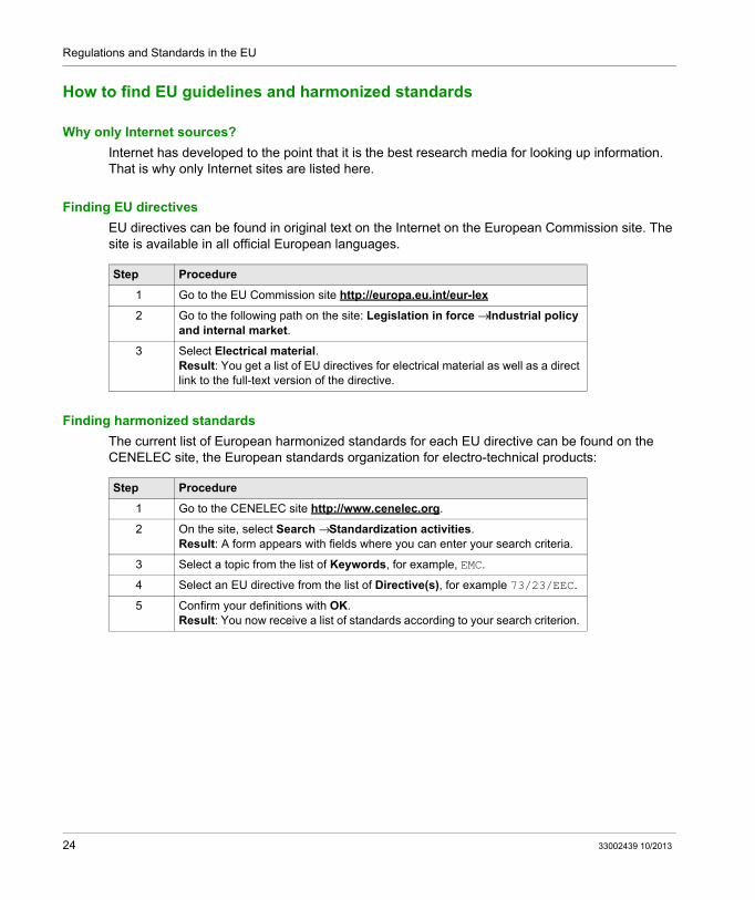
Internet has developed to the point that it is the best research media for looking up information. That is why only Internet sites are listed here.
Finding EU directives
EU directives can be found in original text on the Internet on the European Commission site. The site is available in all official European languages.
Finding harmonized standards
The current list of European harmonized standards for each EU directive can be found on the CENELEC site, the European standards organization for electro-technical products:
Step Procedure
1 Go to the EU Commission site http://europa.eu.int/eur-lex
2 Go to the following path on the site: Legislation in force → Industrial policy and internal market.
3 Select Electrical material.Result: You get a list of EU directives for electrical material as well as a direct link to the full-text version of the directive.
Step Procedure
1 Go to the CENELEC site http://www.cenelec.org.
2 On the site, select Search → Standardization activities. Result: A form appears with fields where you can enter your search criteria.
3 Select a topic from the list of Keywords, for example, EMC.
4 Select an EU directive from the list of Directive(s), for example 73/23/EEC.
5 Confirm your definitions with OK.Result: You now receive a list of standards according to your search criterion.
24 33002439 10/2013
Grounding and Electromagnetic Compatibility of PLC Systems
Standards
33002439 10/2013
International Standards
Chapter 2International Standards
Introduction
This chapter provides information concerning international technical standards for systems and machines in which PLC systems are used.
It explains the purpose for the standards and their role in relation to the regulations. You will also find concrete references to relevant standards.
What Is in This Chapter?
This chapter contains the following topics:
Topic Page
Role of the Standards 26
International Standards 27
Relevant Standards for PLC System Users 28
33002439 10/2013 25
Standards
Role of the Standards
Importance of the standards
The components of a PLC system are produced and tested as well as certified or authorized according to the respective regulations and standards for the country where they are being used.
Not only the manufacturer, but also the user of PLC systems must be aware of the regulations and standards. The automated system in which the components of the PLC system are installed is also subject to regulations. To meet the regulations, the use of standards is helpful and essential as they reflect the current state of technology.
Standards and the law
NOTE: Standards can often provide security concerning product liability, but they are not legal standards. Standardization organizations are not liable for the suitability of the standards. This is tested by the responsible designer through hazard analysis according to machine directives.
What is standardization?
Standardization guarantees uniformity of materials and immaterial things for public use and is carried out according to a plan by interested parties in the community. In addition to company standards, national and international standards are also created.
Standardization serves the following purposes: Promotes rationalization and quality assurance for trade, technology and management Improves safety of personnel and material Improves quality in all areas of life
26 33002439 10/2013
Standards
International Standards
International standards
In many areas, especially electro technical engineering, there are standards which are valid all over the world. The result of these worldwide efforts are 10,000 international standards which are used directly or can be added to the individual national standards. These international standards are defined by international standardization organizations.
ISO
90 countries work together through their national standardization institute in the International Standards Organization (ISO). A well-known example of ISO’s work are the international standards for quality assurance systems ISO 9000 to 9004.
IEC
The International Electro technical Commission (IEC) is responsible for electro technical standards. In this area, there is nearly 100% agreement with the European harmonized standards, which is also evident in the fact that the numbering also matches.
CISPR
CISPR is the International Special Committee on Radio Interference. The goal of CISPR publications and recommendations is to protect radio transmission. CISPR publications mainly contain definitions for test procedures and limit values for radio disturbances for electrical and electronic products.
33002439 10/2013 27
Standards
Relevant Standards for PLC System Users
Introduction
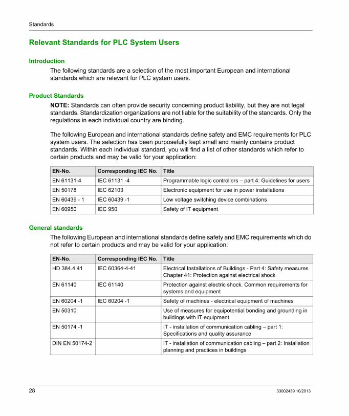
The following standards are a selection of the most important European and international standards which are relevant for PLC system users.
Product Standards
NOTE: Standards can often provide security concerning product liability, but they are not legal standards. Standardization organizations are not liable for the suitability of the standards. Only the regulations in each individual country are binding.
The following European and international standards define safety and EMC requirements for PLC system users. The selection has been purposefully kept small and mainly contains product standards. Within each individual standard, you will find a list of other standards which refer to certain products and may be valid for your application:
General standards
The following European and international standards define safety and EMC requirements which do not refer to certain products and may be valid for your application:
EN-No. Corresponding IEC No. Title
EN 61131-4 IEC 61131 -4 Programmable logic controllers – part 4: Guidelines for users
EN 50178 IEC 62103 Electronic equipment for use in power installations
EN 60439 - 1 IEC 60439 -1 Low voltage switching device combinations
EN 60950 IEC 950 Safety of IT equipment
EN-No. Corresponding IEC No. Title
HD 384.4.41 IEC 60364-4-41 Electrical Installations of Buildings - Part 4: Safety measuresChapter 41: Protection against electrical shock
EN 61140 IEC 61140 Protection against electric shock. Common requirements for systems and equipment
EN 60204 -1 IEC 60204 -1 Safety of machines - electrical equipment of machines
EN 50310 Use of measures for equipotential bonding and grounding in buildings with IT equipment
EN 50174 -1 IT - installation of communication cabling – part 1: Specifications and quality assurance
DIN EN 50174-2 IT - installation of communication cabling – part 2: Installation planning and practices in buildings
28 33002439 10/2013
Grounding and Electromagnetic Compatibility of PLC Systems
Basics
33002439 10/2013
Grounding and Electromagnetic Compatibility (EMC) - Basics
Part IIGrounding and Electromagnetic Compatibility (EMC) - Basics
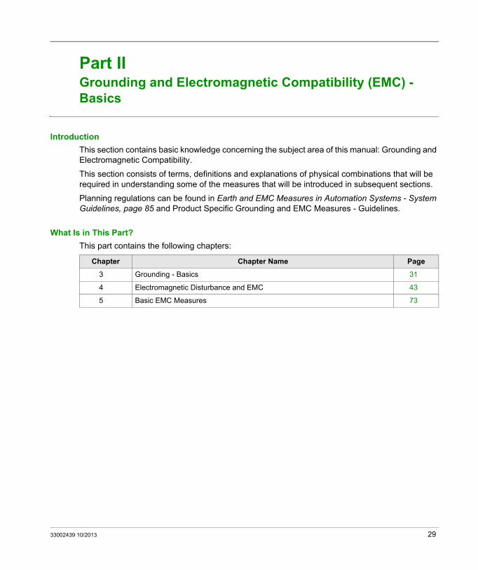
Introduction
This section contains basic knowledge concerning the subject area of this manual: Grounding and Electromagnetic Compatibility.
This section consists of terms, definitions and explanations of physical combinations that will be required in understanding some of the measures that will be introduced in subsequent sections.
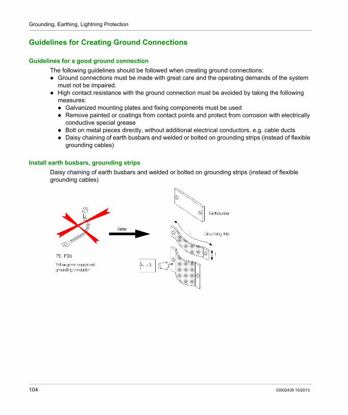
Planning regulations can be found in Earth and EMC Measures in Automation Systems - System Guidelines, page 85 and Product Specific Grounding and EMC Measures - Guidelines.
What Is in This Part?
This part contains the following chapters:
Chapter Chapter Name Page
3 Grounding - Basics 31
4 Electromagnetic Disturbance and EMC 43
5 Basic EMC Measures 73
33002439 10/2013 29
Basics
30 33002439 10/2013
Grounding and Electromagnetic Compatibility of PLC Systems
Grounding
33002439 10/2013
Grounding - Basics
Chapter 3Grounding - Basics
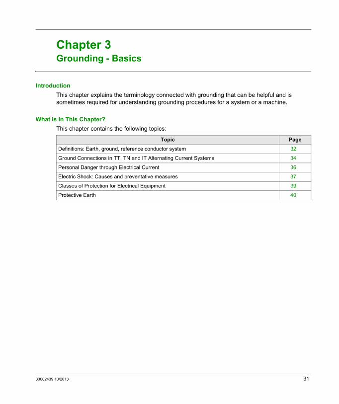
Introduction
This chapter explains the terminology connected with grounding that can be helpful and is sometimes required for understanding grounding procedures for a system or a machine.
What Is in This Chapter?
This chapter contains the following topics:
Topic Page
Definitions: Earth, ground, reference conductor system 32
Ground Connections in TT, TN and IT Alternating Current Systems 34
Personal Danger through Electrical Current 36
Electric Shock: Causes and preventative measures 37
Classes of Protection for Electrical Equipment 39
Protective Earth 40
33002439 10/2013 31
Grounding
Definitions: Earth, ground, reference conductor system
Earth and ground
In almost all devices or systems, you should differentiate between the earth (earth conductor) and the common ground (reference conductor system/neutral connection). Earth and common ground are normally connected to each other in a certain place. However, there is a difference:
NOTE: Earth only conducts fault currents and common ground conducts operational current and is often used as the common conductor for several signal circuits.
Earth
Earth is the conductive potential of our earth. The electrical potential of the earth is considered to be zero. Inside a system, earth is understood as being the protective conductor used for protecting people, animals and goods.
Terms used as synonyms for Earth: Equipment grounding conductor, earth, protective earth, chassis or frame ground, station ground
Ground
This is the common base for all connected conductive inactive components of electrical equipment and is not a route for operational voltage even when a fault occurs. The common ground is the equipotential offset for a system and is used as a common ground plane for electronic circuits.
The common earth plane is normally connected with the earth (grounded) in a stationary system. Common ground does not necessarily have to be connected with earth ground however (in airplanes for example).
Common ground is found performing the following functions: Equipotential plane for the reference conductor system of the electronics Equipotential bonding and over voltage protection for all installations of metal, electrical
systems, lightning protection system and grounding system Protective function for people: Common potential is kept low in relation to earth potential so that
a human would not be harmed by coming into contact with parts of the system Rerouting over-voltages (caused by faults in the system, lightning)
Terms used as synonyms for Common Ground: Equipotential bonding, neutral, switching ground, signal reference, signal ground, measurement ground, 0 V, reference conductor ground
32 33002439 10/2013
Grounding
Common ground examples
Common ground examples: Metallic structural elements of a building (framework, piping, etc.) Motor housing Metal cabinets, unpainted floor plates on housings Metallic cable ducts Transformer housing, machine bed plate Yellow-green wire (PE-PEN) for grounding
Reference conductor, reference conductor systems
The reference conductor for an electronic operation is the reference potential. It is connected with the common ground.
The reference conductor system makes a galvanized connection of all 0 Volt wires that are required in the current loop of the electrical equipment. No voltage differences may exist between the various points of the electronic reference plane otherwise unintended signal voltages can occur.
Normally, several circuits are operated on a common reference conductor system for the exchange of necessary signals.
Terms used as synonyms for Reference Conductor systems: Neutral (system)
33002439 10/2013 33
Grounding
Ground Connections in TT, TN and IT Alternating Current Systems
Distribution systems
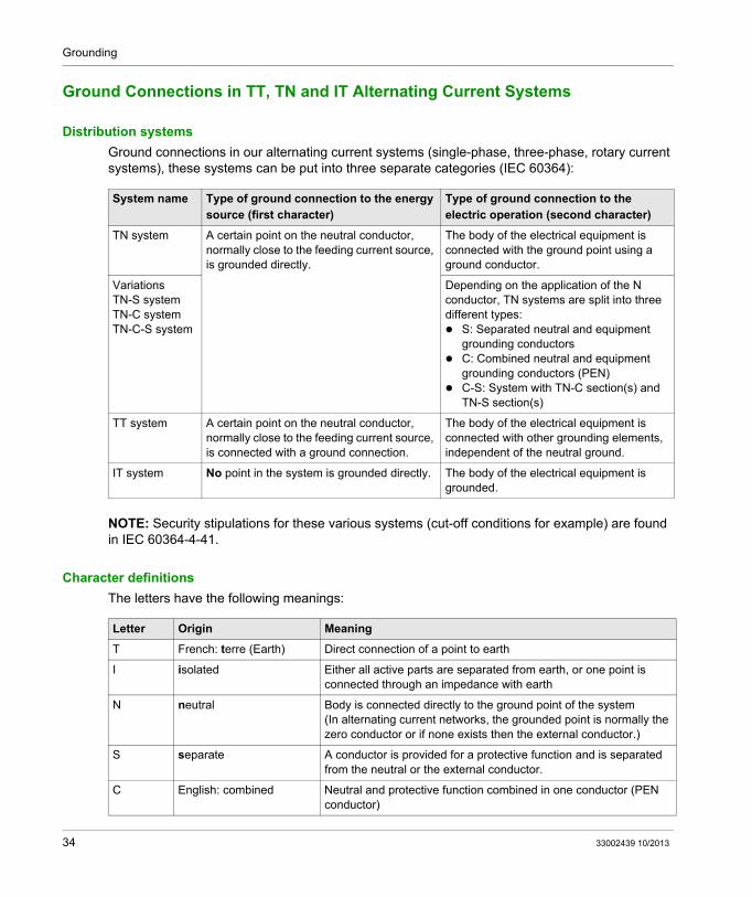
Ground connections in our alternating current systems (single-phase, three-phase, rotary current systems), these systems can be put into three separate categories (IEC 60364):
NOTE: Security stipulations for these various systems (cut-off conditions for example) are found in IEC 60364-4-41.
Character definitions
The letters have the following meanings:
System name Type of ground connection to the energy source (first character)
Type of ground connection to the electric operation (second character)
TN system A certain point on the neutral conductor, normally close to the feeding current source, is grounded directly.
The body of the electrical equipment is connected with the ground point using a ground conductor.
VariationsTN-S systemTN-C systemTN-C-S system
Depending on the application of the N conductor, TN systems are split into three different types: S: Separated neutral and equipment
grounding conductors C: Combined neutral and equipment
grounding conductors (PEN) C-S: System with TN-C section(s) and
TN-S section(s)
TT system A certain point on the neutral conductor, normally close to the feeding current source, is connected with a ground connection.
The body of the electrical equipment is connected with other grounding elements, independent of the neutral ground.
IT system No point in the system is grounded directly. The body of the electrical equipment is grounded.
Letter Origin Meaning
T French: terre (Earth) Direct connection of a point to earth
I isolated Either all active parts are separated from earth, or one point is connected through an impedance with earth
N neutral Body is connected directly to the ground point of the system(In alternating current networks, the grounded point is normally the zero conductor or if none exists then the external conductor.)
S separate A conductor is provided for a protective function and is separated from the neutral or the external conductor.
C English: combined Neutral and protective function combined in one conductor (PEN conductor)
34 33002439 10/2013
Grounding
First and second letter assignment
The identifying letters for the current distribution system are assigned as follows: First letter: Indicates the ground connection to the energy source (Transformer for example) Second letter: Indicates the ground connection to the electrical equipment
33002439 10/2013 35
Grounding
Personal Danger through Electrical Current
Dangerous Body Currents (Electrical Shock)
An electrical shock is the result of current flowing through the human body. Currents of 1 mA can cause reactions in a person of good health which can in turn cause shock to a dangerous degree. Higher levels of current can result in more damage. In dry conditions, voltages to around 42.4 V peak value or 60 V constant voltage are not normally considered dangerous.
Components that must be touched or gripped should be connected with protective ground or should be sufficiently insulated.
Energy hazards
Short circuits between neighboring poles of power supply devices of higher current levels or circuits with high capacity can cause arcing or sparking of hot metal particles and result in burns. Even low voltage circuits can be dangerous in this way.
Protection is achieved by separation or safety devices.
Burns
A burn can be caused by temperatures that are the result of overloads, component failures, insulation damage or loose connections or those with high transition resistance.
The protective measures concern prevention of burns, the selection of materials regarding inflammability, measures for limiting the spreading of burns, etc.
Miscellaneous indirect hazards
Other indirect dangers Dangers of heat: Danger of injury caused by touching hot components. Dangers of radiation: Hazardous radiation, e.g., noise, high frequency radiation, infrared
radiation, visible and coherent light of high intensity, ultraviolet and ionizing radiation, etc. Chemical hazards: Danger of contact with dangerous chemical materials.
36 33002439 10/2013
Grounding
Electric Shock: Causes and preventative measures
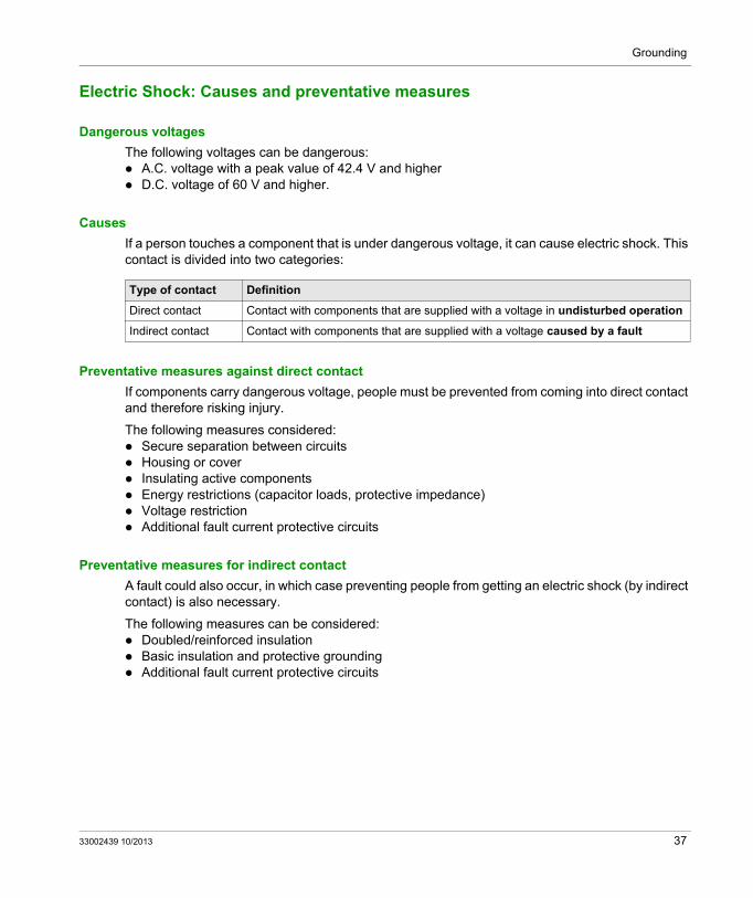
Dangerous voltages
The following voltages can be dangerous: A.C. voltage with a peak value of 42.4 V and higher D.C. voltage of 60 V and higher.
Causes
If a person touches a component that is under dangerous voltage, it can cause electric shock. This contact is divided into two categories:
Preventative measures against direct contact
If components carry dangerous voltage, people must be prevented from coming into direct contact and therefore risking injury.
The following measures considered: Secure separation between circuits Housing or cover Insulating active components Energy restrictions (capacitor loads, protective impedance) Voltage restriction Additional fault current protective circuits
Preventative measures for indirect contact
A fault could also occur, in which case preventing people from getting an electric shock (by indirect contact) is also necessary.
The following measures can be considered: Doubled/reinforced insulation Basic insulation and protective grounding Additional fault current protective circuits
Type of contact Definition
Direct contact Contact with components that are supplied with a voltage in undisturbed operation
Indirect contact Contact with components that are supplied with a voltage caused by a fault
33002439 10/2013 37
Grounding
Respective standards
Regulations for protective measures against electric shock are covered in the following standards: Safety regulation standard:
IEC 61140: Protection against electric shock. Common requirements for systems and electrical equipment (safety standards)
Safety group standards:IEC 60364-4-41: Electrical Installations of Buildings - Part 4: Protection for Safety, Chapter 41: Protection against electrical shock
For systems:IEC 62103 and EN 50178: Electronic equipment for use in power installations
For machines:IEC 60204: Safety of machines - electrical equipment of machines
38 33002439 10/2013
Grounding
Classes of Protection for Electrical Equipment
Classes of Protection
Electrical equipment is divided in protection classes 0, I, II and III. These classes of protection are defined by the method in which the protection against electric shock is achieved (IEC 61140).
Programmable Logic Controllers and their peripherals must correspond with protective classes I, II or III (according to IEC 61131-2).
Protective Class 0
Electrical equipment for which the protection against dangerous body currents only contacts the basic insulation belongs to protective class 0. This means that no medium for connecting conductive components to the protective conductor (ground conductor) is provided in the permanent wiring of the system. If the basic insulation fails then the surrounding environment is trusted.
Protective Class I
Electrical equipment for which the protection against dangerous body currents does not only contact the basic insulation belongs to protective class I. An additional contact for connecting conductive components to the protective conductor (ground conductor) is provided in the permanent wiring of the system. Components that can be touched are voltage-free if the basic insulation fails in this case.
Protective Class II
Electrical equipment for which the protection against dangerous body currents does not only contact the basic insulation belongs to protective class II. An additional safety feature such as doubled insulation or reinforced insulation is provided but no protective ground.
Protective Class III
Electrical equipment for which the protection against dangerous body currents is achieved by safety extra-low voltage (SELV) supply belongs to protective class II. In this type of electrical equipment, no voltage that is higher than the SELV is produced.
SELV
SELV (Safety extra-low voltage): is defined as a voltage that, measured between conductors or between a conductor and ground, does not exceed 42.4 V peak or constant voltage. The circuits in which these are used must be separated from the power supply by a safety transformer or a similar device.
33002439 10/2013 39
Grounding
Protective Earth
Alternatives: Insulation or protective earth
All components of a system or machine that can be applied with a dangerous voltage if a fault occurs must be taken into account. To guarantee safety, these components can either be double insulated or reinforced or they can be equipped with a protective earth.
Protective earth: Definition
Protective earth is the earth that is mainly for guaranteeing the safety of human beings.
The protective earth is a preventative measure for avoiding an electric shock caused by indirect contact, i.e., contact with a component that has been applied with a dangerous voltage as a result of a fault - failure in the basic insulation for example.
NOTE: The protective earth is clearly separate from the functional earth. The functional earth is not for safety, it is a functional component; it is used as a reference voltage or for rerouting interference current for example.
Grounding arrangements and protective conductors
The precision of the connection to the ground potential depends on the electrical equipment, the components and the type of current distribution (TT, TN, IT system).
Some important standard principles for protective earth are: The cross section of the protective ground wire must correspond with the maximum expected
leakage current. Electrical connections must correspond with the loads that are possible in practical operation. The protective ground must also be guaranteed operational during service and maintenance
work. The protective earth overrides the functional earth. It may not e.g. be used to disabled to
improve the electromagnetic compatibility.
NOTE: IEC 60364-5-54 contains requirements for the earth system and protective grounding conductors.
40 33002439 10/2013
Grounding
Protective earth for PLCs
Programmable Logic Controllers and their peripherals that belong to protective class I have a protective earth connection.
There are two ways of connecting to the earth system: The protective conductor is found in the power supply wire directly from the electric supply
(mains). The device has a protective conductor connection for connecting to an external protective
conductor.
All components of the device that a person can come into contact with (e.g. frame, housing, mounts) are connected electrically and are connected with the protective conductor connection so that no dangerous voltage can enter. The protective conductor connection must remain intact when working on the device as long as the supply is connected.
Requirements for the construction of PLCs and their peripherals can be found in IEC 61131-2 Programmable Controllers, Part 2: Equipment requirements and tests.
33002439 10/2013 41
Grounding
42 33002439 10/2013
Grounding and Electromagnetic Compatibility of PLC Systems
EMC Basics
33002439 10/2013
Electromagnetic Disturbance and EMC
Chapter 4Electromagnetic Disturbance and EMC
Introduction
This chapter contains the electronics basics on electromagnetic disturbance. This is based on the following questions: What can electromagnetic disturbances in industrial applications actually result in? What are the sources of disturbance? How can disturbance signals interfere with useful signals? What types of coupling mechanisms are there and what measures should be used to avoid
problems?
This knowledge is necessary in understanding possible disturbance phenomena and the preventative measures that you can take in the planning and installation of the electrical equipment in an industrial application.
What Is in This Chapter?
This chapter contains the following sections:
Section Topic Page
4.1 Results, Causes and Types of Disturbance 44
4.2 Overlapping of Interference and Useful Signals on Wires 53
4.3 Interference Coupling 60
33002439 10/2013 43
EMC Basics
Results, Causes and Types of Disturbance
Section 4.1Results, Causes and Types of Disturbance
Introduction
Electromagnetic disturbance in industrial applications can affect operation to various degrees: From acceptable operational influences right up to damaged system components. The causes of these disturbances lie either within the system or outside of it and can be classified according to various criteria. The disturbances themselves can vary and are also classified according to different criteria.
This section is concerned with the results, causes and types of disturbance. It can mainly be used for understanding the terminology and for classification and is therefore required for a complete understanding of the other sections of the document.
What Is in This Section?
This section contains the following topics:
Topic Page
Results of Disturbance to an Industrial Application 45
Principles of Interference Influence - Influence Model 46
Sources of Interference 47
Interference Variables and Interference Signals 50
Effective Parameters 52
44 33002439 10/2013
EMC Basics
Results of Disturbance to an Industrial Application
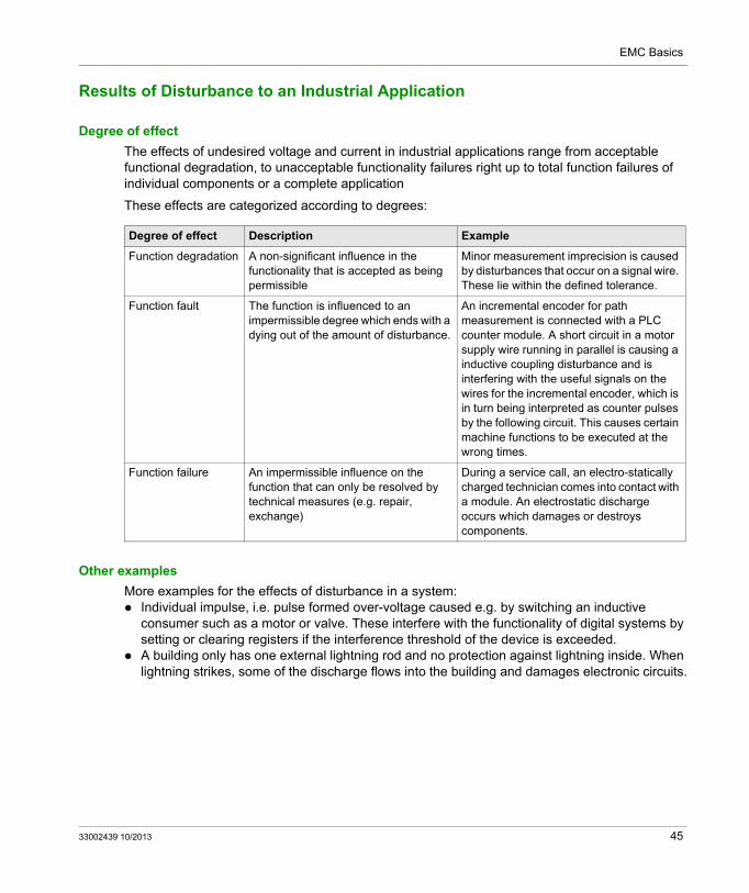
Degree of effect
The effects of undesired voltage and current in industrial applications range from acceptable functional degradation, to unacceptable functionality failures right up to total function failures of individual components or a complete application
These effects are categorized according to degrees:
Other examples
More examples for the effects of disturbance in a system: Individual impulse, i.e. pulse formed over-voltage caused e.g. by switching an inductive
consumer such as a motor or valve. These interfere with the functionality of digital systems by setting or clearing registers if the interference threshold of the device is exceeded.
A building only has one external lightning rod and no protection against lightning inside. When lightning strikes, some of the discharge flows into the building and damages electronic circuits.
Degree of effect Description Example
Function degradation A non-significant influence in the functionality that is accepted as being permissible
Minor measurement imprecision is caused by disturbances that occur on a signal wire. These lie within the defined tolerance.
Function fault The function is influenced to an impermissible degree which ends with a dying out of the amount of disturbance.
An incremental encoder for path measurement is connected with a PLC counter module. A short circuit in a motor supply wire running in parallel is causing a inductive coupling disturbance and is interfering with the useful signals on the wires for the incremental encoder, which is in turn being interpreted as counter pulses by the following circuit. This causes certain machine functions to be executed at the wrong times.
Function failure An impermissible influence on the function that can only be resolved by technical measures (e.g. repair, exchange)
During a service call, an electro-statically charged technician comes into contact with a module. An electrostatic discharge occurs which damages or destroys components.
33002439 10/2013 45
EMC Basics
Principles of Interference Influence - Influence Model
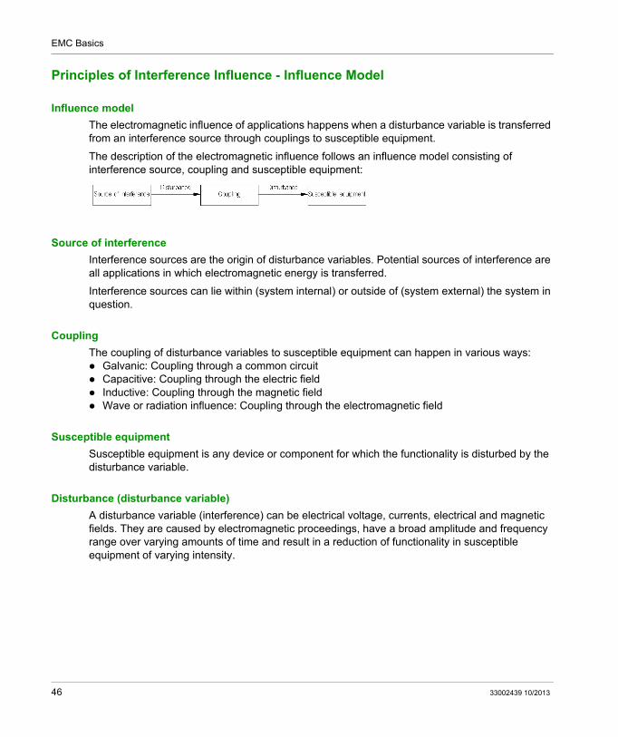
Influence model
The electromagnetic influence of applications happens when a disturbance variable is transferred from an interference source through couplings to susceptible equipment.
The description of the electromagnetic influence follows an influence model consisting of interference source, coupling and susceptible equipment:
Source of interference
Interference sources are the origin of disturbance variables. Potential sources of interference are all applications in which electromagnetic energy is transferred.
Interference sources can lie within (system internal) or outside of (system external) the system in question.
Coupling
The coupling of disturbance variables to susceptible equipment can happen in various ways: Galvanic: Coupling through a common circuit Capacitive: Coupling through the electric field Inductive: Coupling through the magnetic field Wave or radiation influence: Coupling through the electromagnetic field
Susceptible equipment
Susceptible equipment is any device or component for which the functionality is disturbed by the disturbance variable.
Disturbance (disturbance variable)
A disturbance variable (interference) can be electrical voltage, currents, electrical and magnetic fields. They are caused by electromagnetic proceedings, have a broad amplitude and frequency range over varying amounts of time and result in a reduction of functionality in susceptible equipment of varying intensity.
46 33002439 10/2013
EMC Basics
Sources of Interference
Classification of sources of interference
The following classification for sources of interference can be helpful: Natural and technical sources Sources having narrow-band and broad-band frequency spectrums Sources for conductor and radiated disturbance variables Power supply as source of interference Regular and unintended (leakage) sources Continuous and intermittent sources
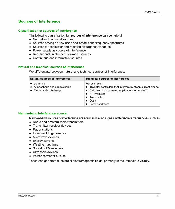
Natural and technical sources of interference
We differentiate between natural and technical sources of interference:
Narrow-band interference source
Narrow-band sources of interference are sources having signals with discrete frequencies such as: Radio and amateur radio transmitters Transmitter receiver devices Radar stations Industrial HF generators Microwave devices Energy currents Welding machines Sound or FX receivers Ultrasonic devices Power converter circuits
These can generate substantial electromagnetic fields, primarily in the immediate vicinity.
Natural sources of interference Technical sources of interference
Lightning Atmospheric and cosmic noise Electrostatic discharge
For example: Thyristor controllers that interfere by steep current slopes Switching high powered applications on and off HF Producer Transmitter Oven Local oscillators
33002439 10/2013 47
EMC Basics
Broad-band interference sources
Broad-band sources of interference of conducted and radiated disturbance variables are feared disruptors in electronic automation systems, since they have very high frequencies in addition to a wide frequency spectrum.
The following belong to the broad-band sources of interference: Motors Discharge lamps Circuit breakers (power switches) Isolating switches in energy supplies Noise Controller circuits with semi-conductors Switching devices (relay, contact) Electrostatic discharge Atmospheric discharge Corona Nuclear discharge
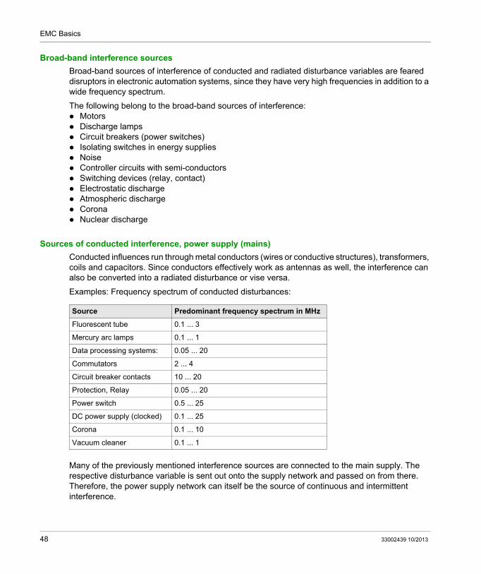
Sources of conducted interference, power supply (mains)
Conducted influences run through metal conductors (wires or conductive structures), transformers, coils and capacitors. Since conductors effectively work as antennas as well, the interference can also be converted into a radiated disturbance or vise versa.
Examples: Frequency spectrum of conducted disturbances:
Many of the previously mentioned interference sources are connected to the main supply. The respective disturbance variable is sent out onto the supply network and passed on from there. Therefore, the power supply network can itself be the source of continuous and intermittent interference.
Source Predominant frequency spectrum in MHz
Fluorescent tube 0.1 ... 3
Mercury arc lamps 0.1 ... 1
Data processing systems: 0.05 ... 20
Commutators 2 ... 4
Circuit breaker contacts 10 ... 20
Protection, Relay 0.05 ... 20
Power switch 0.5 ... 25
DC power supply (clocked) 0.1 ... 25
Corona 0.1 ... 10
Vacuum cleaner 0.1 ... 1
48 33002439 10/2013
EMC Basics
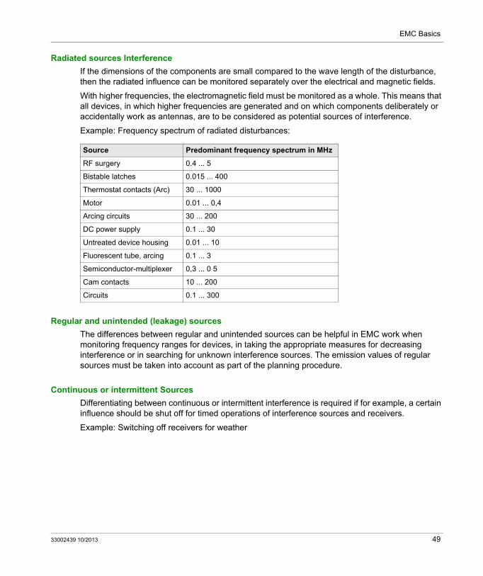
Radiated sources Interference
If the dimensions of the components are small compared to the wave length of the disturbance, then the radiated influence can be monitored separately over the electrical and magnetic fields.
With higher frequencies, the electromagnetic field must be monitored as a whole. This means that all devices, in which higher frequencies are generated and on which components deliberately or accidentally work as antennas, are to be considered as potential sources of interference.
Example: Frequency spectrum of radiated disturbances:
Regular and unintended (leakage) sources
The differences between regular and unintended sources can be helpful in EMC work when monitoring frequency ranges for devices, in taking the appropriate measures for decreasing interference or in searching for unknown interference sources. The emission values of regular sources must be taken into account as part of the planning procedure.
Continuous or intermittent Sources
Differentiating between continuous or intermittent interference is required if for example, a certain influence should be shut off for timed operations of interference sources and receivers.
Example: Switching off receivers for weather
Source Predominant frequency spectrum in MHz
RF surgery 0.4 ... 5
Bistable latches 0.015 ... 400
Thermostat contacts (Arc) 30 ... 1000
Motor 0.01 ... 0,4
Arcing circuits 30 ... 200
DC power supply 0.1 ... 30
Untreated device housing 0.01 ... 10
Fluorescent tube, arcing 0.1 ... 3
Semiconductor-multiplexer 0,3 ... 0 5
Cam contacts 10 ... 200
Circuits 0.1 ... 300
33002439 10/2013 49
EMC Basics
Interference Variables and Interference Signals
Overview
The disturbance variables and the interfering signals that result from them cover a wide frequency and amplitude range. They can occur in many curve forms and be put into many different classifications.
When referring to time, the occurrences are classified as periodical and non-periodic interference variables.
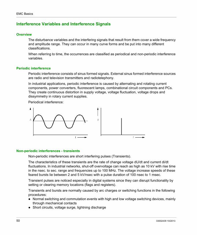
Periodic interference
Periodic interference consists of sinus formed signals. External sinus formed interference sources are radio and television transmitters and radiotelephony.
In industrial applications, periodic interference is caused by alternating and rotating current components, power converters, fluorescent lamps, combinational circuit components and PCs. They create continuous distortion in supply voltage, voltage fluctuation, voltage drops and dissymmetry in rotary current supplies.
Periodical interference:
Non-periodic interferences - transients
Non-periodic interferences are short interfering pulses (Transients).
The characteristics of these transients are the rate of change voltage dU/dt and current di/dt fluctuations. In industrial networks, shut-off overvoltage can reach as high as 10 kV with rise time in the nsec. to sec. range and frequencies up to 100 MHz. The voltage increase speeds of these feared bursts lie between 2 and 5 kV/nsec with a pulse duration of 100 nsec to 1 msec.
Transient pulses are noticed especially in digital systems since they can disrupt functionality by setting or clearing memory locations (flags and registers).
Transients and bursts are normally caused by arc charges or switching functions in the following procedures: Normal switching and commutation events with high and low voltage switching devices, mainly
through mechanical contacts Short circuits, voltage surge, lightning discharge
50 33002439 10/2013
EMC Basics
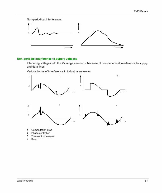
Non-periodical interference:
Non-periodic interference to supply voltages
Interfering voltages into the kV range can occur because of non-periodical interference to supply and data lines.
Various forms of interference in industrial networks:
Parameters for interference variables are: Rise time: as a measurement of the duration of the interference Rate of change du/dt, di/dt: as a measurement of the intensity of the interference Peak value: as a measurement of the energy of the interference
Causes of effective interference
NOTE: Causes of effective interference are exclusively amplitude variations in electrical parameters per time unit. The duration of the interference is identical to the duration of the change in the source of interference.
Frequency influence
The frequency spectrum of a disturbance variable is important because the inductive resistance and the capacitive resistance on a conductor depend on the frequency. The higher the frequency of the interference, the higher the interfering signal. Frequent interference signals cause a voltage drop on the inductive resistance of conductors which shows up as interference voltage. This causes a carrier flow on the line capacity that shows up as interference current.
Frequency spectrum of an interference pulse
To simplify matters, an interference pulse can be considered as a rectangular pulse form. This can be calculated as a sum of sinus functions. To recreate this pulse more precisely, i.e. the more slope that is defined for a pulse edge, the more frequent the required voltages must be.
52 33002439 10/2013
EMC Basics
Overlapping of Interference and Useful Signals on Wires
Section 4.2Overlapping of Interference and Useful Signals on Wires
Introduction
The structure of electrical circuits is important to the way that an interference signal disrupts the useful signals and how well that the interference signal can be separated from the useful signal.
This section explains the terms symmetric and asymmetric electrical circuits and the common mode interference and the differential mode interference as the principal types of overlaying of interference and useful signals in electrical circuits.
These basics are required in order to understand the EMC measures for balancing circuits.
What Is in This Section?
This section contains the following topics:
Topic Page
Symmetrically and Asymmetrically Operated Circuits 54
Differential Mode Interference 55
Common Mode Interference 57
Common Mode-Differential Mode-Conversion 59
33002439 10/2013 53
EMC Basics
Symmetrically and Asymmetrically Operated Circuits
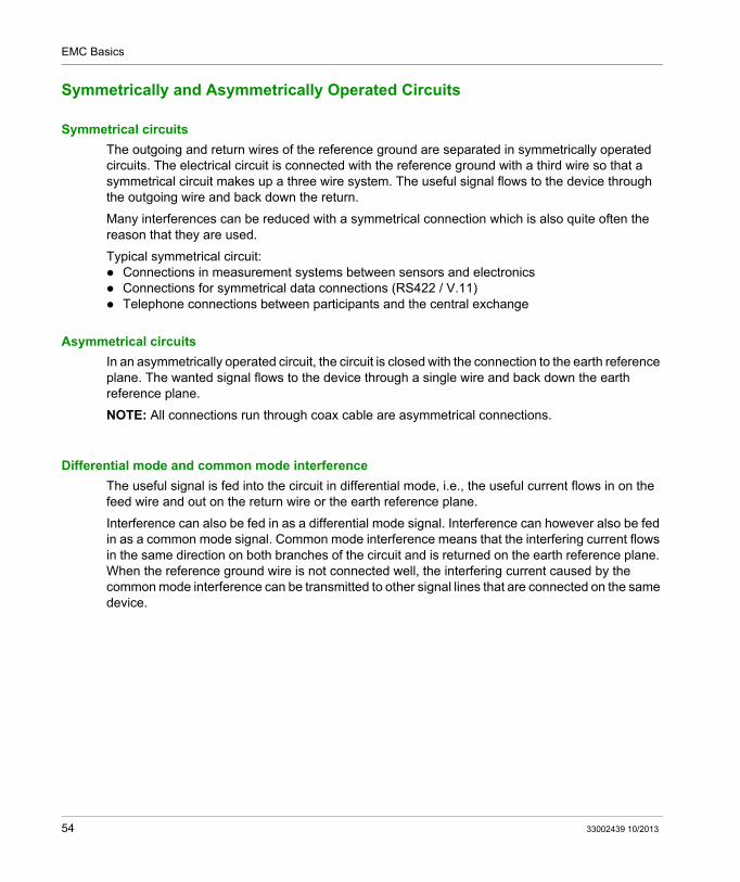
Symmetrical circuits
The outgoing and return wires of the reference ground are separated in symmetrically operated circuits. The electrical circuit is connected with the reference ground with a third wire so that a symmetrical circuit makes up a three wire system. The useful signal flows to the device through the outgoing wire and back down the return.
Many interferences can be reduced with a symmetrical connection which is also quite often the reason that they are used.
Typical symmetrical circuit: Connections in measurement systems between sensors and electronics Connections for symmetrical data connections (RS422 / V.11) Telephone connections between participants and the central exchange
Asymmetrical circuits
In an asymmetrically operated circuit, the circuit is closed with the connection to the earth reference plane. The wanted signal flows to the device through a single wire and back down the earth reference plane.
NOTE: All connections run through coax cable are asymmetrical connections.
Differential mode and common mode interference
The useful signal is fed into the circuit in differential mode, i.e., the useful current flows in on the feed wire and out on the return wire or the earth reference plane.
Interference can also be fed in as a differential mode signal. Interference can however also be fed in as a common mode signal. Common mode interference means that the interfering current flows in the same direction on both branches of the circuit and is returned on the earth reference plane. When the reference ground wire is not connected well, the interfering current caused by the common mode interference can be transmitted to other signal lines that are connected on the same device.
54 33002439 10/2013
EMC Basics
Differential Mode Interference
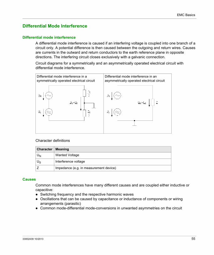
Differential mode interference
A differential mode interference is caused if an interfering voltage is coupled into one branch of a circuit only. A potential difference is then caused between the outgoing and return wires. Causes are currents in the outward and return conductors to the earth reference plane in opposite directions. The interfering circuit closes exclusively with a galvanic connection.
Circuit diagrams for a symmetrically and an asymmetrically operated electrical circuit with differential mode interference.
Character definitions
Causes
Common mode interferences have many different causes and are coupled either inductive or capacitive: Switching frequency and the respective harmonic waves Oscillations that can be caused by capacitance or inductance of components or wiring
arrangements (parasitic) Common mode-differential mode-conversions in unwanted asymmetries on the circuit
Differential mode interference in a symmetrically operated electrical circuit
Differential mode interference in an asymmetrically operated electrical circuit
Character Meaning
UN Wanted Voltage
US Interference voltage
Z Impedance (e.g. in measurement device)
33002439 10/2013 55
EMC Basics
Separation of useful and interfering signals
NOTE: Useful signals and interference signals cannot be separated from one another in symmetrical or asymmetrical operations. Therefore, differential mode interference should be avoided.
56 33002439 10/2013
EMC Basics
Common Mode Interference
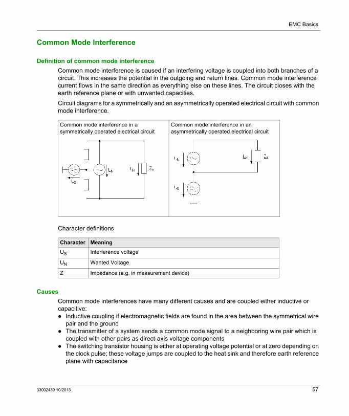
Definition of common mode interference
Common mode interference is caused if an interfering voltage is coupled into both branches of a circuit. This increases the potential in the outgoing and return lines. Common mode interference current flows in the same direction as everything else on these lines. The circuit closes with the earth reference plane or with unwanted capacities.
Circuit diagrams for a symmetrically and an asymmetrically operated electrical circuit with common mode interference.
Character definitions
Causes
Common mode interferences have many different causes and are coupled either inductive or capacitive: Inductive coupling if electromagnetic fields are found in the area between the symmetrical wire
pair and the ground The transmitter of a system sends a common mode signal to a neighboring wire pair which is
coupled with other pairs as direct-axis voltage components The switching transistor housing is either at operating voltage potential or at zero depending on
the clock pulse; these voltage jumps are coupled to the heat sink and therefore earth reference plane with capacitance
Common mode interference in a symmetrically operated electrical circuit
Common mode interference in an asymmetrically operated electrical circuit
Character Meaning
US Interference voltage
UN Wanted Voltage
Z Impedance (e.g. in measurement device)
33002439 10/2013 57
EMC Basics
Common mode-differential mode-conversion
Normally, interference occurs in the form of linear or common mode voltage and only then causes an interfering differential mode signal because of insufficient symmetry.
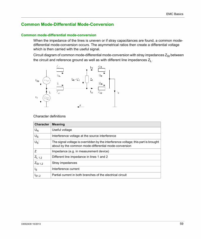
When the impedance of the lines is uneven or if stray capacities are found, a common mode-differential mode-conversion occurs. The asymmetrical ratios then create a differential voltage which is then carried with the useful signal.
As soon as anything asymmetric occurs a coupling of the interference source to the useful load occurs.
58 33002439 10/2013
EMC Basics
Common Mode-Differential Mode-Conversion
Common mode-differential mode-conversion
When the impedance of the lines is uneven or if stray capacitances are found, a common mode-differential mode-conversion occurs. The asymmetrical ratios then create a differential voltage which is then carried with the useful signal.
Circuit diagram of common mode-differential mode-conversion with stray impedances ZSt between
the circuit and reference ground as well as with different line impedances ZL.
Character definitions
Character Meaning
UN Useful voltage
US Interference voltage at the source interference
US’ The signal voltage is overridden by the interference voltage; this part is brought about by the common mode-differential mode-conversion
Z Impedance (e.g. in measurement device)
ZL 1,2 Different line impedance in lines 1 and 2
ZSt 1,2 Stray impedances
IS Interference current
IS1,2 Partial current in both branches of the electrical circuit
33002439 10/2013 59
EMC Basics
Interference Coupling
Section 4.3Interference Coupling
Introduction
Interference has various methods of coupling into the electrical equipment and spreading. The different coupling methods or coupling mechanisms are described in this section. You will also read about which parameters determine the size of the coupled interference signals. At the end of the section you will find a table overview indicating the measures to take for each type of coupling.
A sound knowledge of coupling mechanisms, the influential parameters and the proper basic solutions is necessary for understanding and selecting the proper EMC measures in an industrial application.
What Is in This Section?
This section contains the following topics:
Topic Page
Interference Coupling Mechanisms 61
Galvanic Coupling 63
Inductive Coupling 66
Capacitive Coupling 68
Radiating Coupling 70
Wave Influence 71
Which measures for which type of coupling? 72
60 33002439 10/2013
EMC Basics
Interference Coupling Mechanisms
Overview
To put the proper EMC measures to use during planning and in service, you need to know types, effects and methods of transfer of the coupled interference. This is the only way to effectively combat the problems.
Generally, the physical laws of energy transfer in electromagnetic fields apply for the coupling.
Methods of transfer
The interference can be transferred along a conductive wire (guided) or through space (unguided/radiated). Interferences are normally found together as line guided and radiated interference and are coupled to inputs, outputs, the power supply and data lines.
"Size" Wave lengths
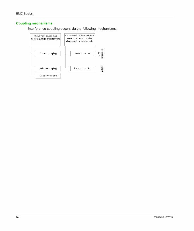
If the wave lengths of the interference variables are greater that the characteristic measurements of the source and receiver, the transfer mechanisms for electrical and magnetic fields are monitored separately. Galvanic coupling with common impedances on the influential electrical circuits (source and
receiver) Inductive coupling with the common magnetic field of source and receiver (low pass field
coupling) Capacitive coupling with the electrical field between the source and receiver (low pass field
coupling)
"Small" Wave lengths
If the wave lengths of the interference are the same or are less than the characteristic measurements of the source and receiver, a coupling over the electromagnetic field must be monitored. The following influential mechanisms play a part: Wave influence with wave activity on lines Radiated coupling through space
33002439 10/2013 61
EMC Basics
Coupling mechanisms
Interference coupling occurs via the following mechanisms:
62 33002439 10/2013
EMC Basics
Galvanic Coupling
Mechanism
Galvanic coupling is a line guided coupling. This phenomenon occurs if shared line sections belong to different circuits. With every change in current in one of the circuits a voltage change is made on the common line so that the circuits influence each other.
Galvanic coupling typically occurs on the following circuits: Coupling of different circuits to the same power supply Coupling between operational circuits and grounding circuits (earth circuit coupling) Coupling different circuits with a common reference conductor system
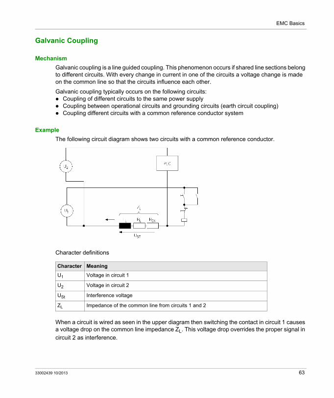
Example
The following circuit diagram shows two circuits with a common reference conductor.
Character definitions
When a circuit is wired as seen in the upper diagram then switching the contact in circuit 1 causes a voltage drop on the common line impedance ZL. This voltage drop overrides the proper signal in
circuit 2 as interference.
Character Meaning
U1 Voltage in circuit 1
U2 Voltage in circuit 2
USt Interference voltage
ZL Impedance of the common line from circuits 1 and 2
33002439 10/2013 63
EMC Basics
Size of the interference
The intensity of the interference is determined by the impedance of the common conductor and the size of the change in current.
NOTE: Especially highly frequent transient interference currents can cause extreme voltage drops.
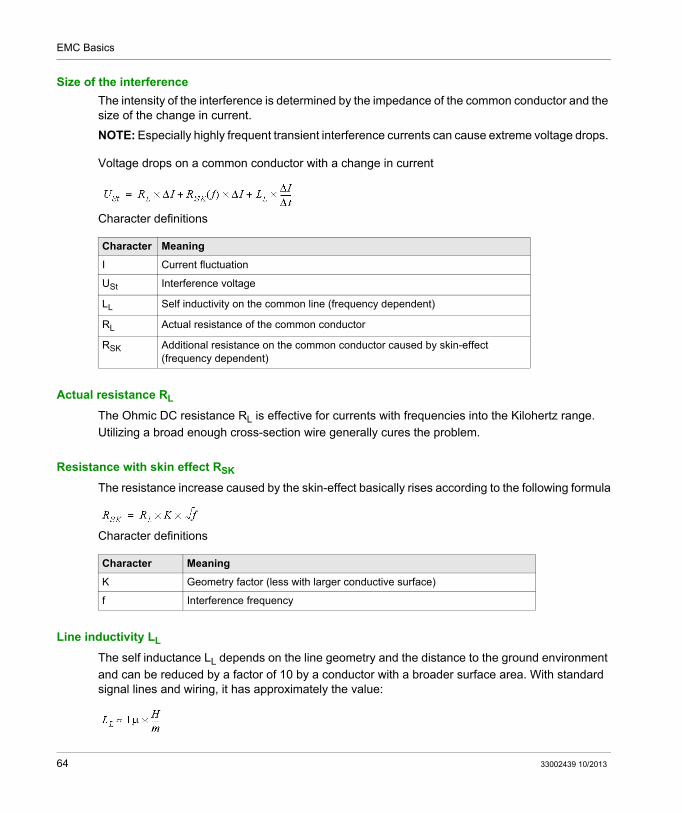
Voltage drops on a common conductor with a change in current
Character definitions
Actual resistance RL
The Ohmic DC resistance RL is effective for currents with frequencies into the Kilohertz range.
Utilizing a broad enough cross-section wire generally cures the problem.
Resistance with skin effect RSK
The resistance increase caused by the skin-effect basically rises according to the following formula
Character definitions
Line inductivity LL
The self inductance LL depends on the line geometry and the distance to the ground environment
and can be reduced by a factor of 10 by a conductor with a broader surface area. With standard signal lines and wiring, it has approximately the value:
Character Meaning
I Current fluctuation
USt Interference voltage
LL Self inductivity on the common line (frequency dependent)
RL Actual resistance of the common conductor
RSK Additional resistance on the common conductor caused by skin-effect (frequency dependent)
Character Meaning
K Geometry factor (less with larger conductive surface)
f Interference frequency
64 33002439 10/2013
EMC Basics
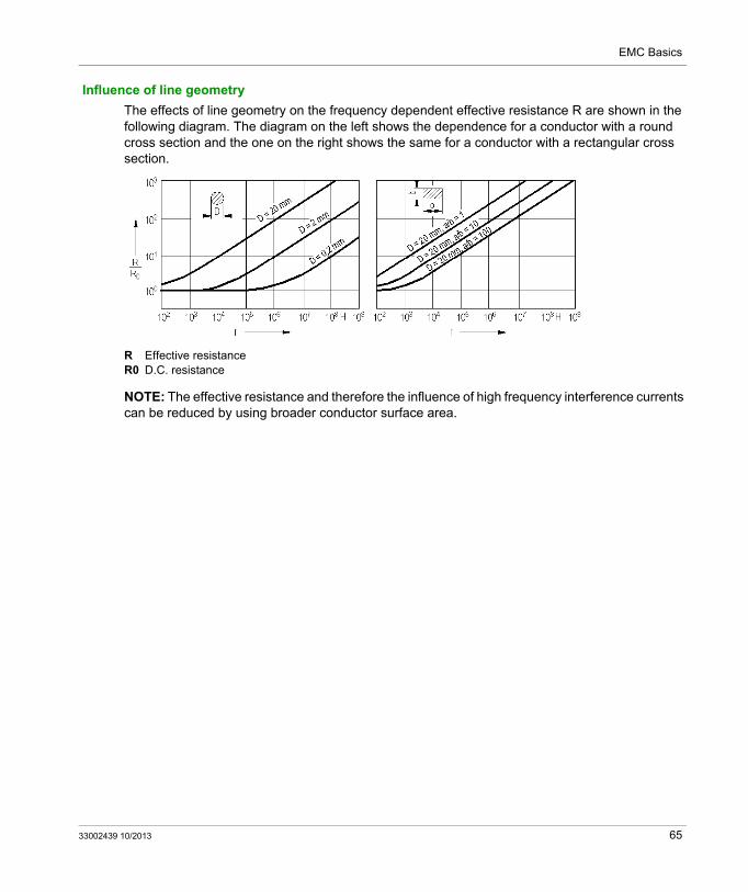
Influence of line geometry
The effects of line geometry on the frequency dependent effective resistance R are shown in the following diagram. The diagram on the left shows the dependence for a conductor with a round cross section and the one on the right shows the same for a conductor with a rectangular cross section.
R Effective resistanceR0 D.C. resistance
NOTE: The effective resistance and therefore the influence of high frequency interference currents can be reduced by using broader conductor surface area.
33002439 10/2013 65
EMC Basics
Inductive Coupling
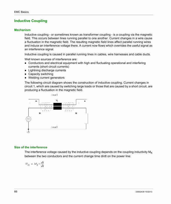
Mechanism
Inductive coupling - or sometimes known as transformer coupling - is a coupling via the magnetic field. This occurs between lines running parallel to one another. Current changes in a wire cause a fluctuation in the magnetic field. The resulting magnetic field lines affect parallel running wires and induce an interference voltage there. A current now flows which overrides the useful signal as an interference signal.
Inductive coupling is caused in parallel running lines in cables, wire harnesses and cable ducts.
Well known sources of interference are: Conductors and electrical equipment with high and fluctuating operational and interfering
The following circuit diagram shows the construction of inductive coupling. Current changes in circuit 1, which are caused by switching large loads or those that are caused by a short circuit, are producing a fluctuation in the magnetic field.
Size of the interference
The interference voltage caused by the inductive coupling depends on the coupling inductivity MK
between the two conductors and the current change time di/dt on the power line:
66 33002439 10/2013
EMC Basics
Coupling inductivity MK
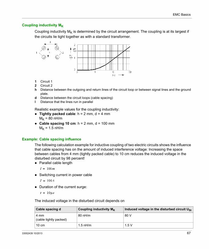
Coupling inductivity MK is determined by the circuit arrangement. The coupling is at its largest if
the circuits lie tight together as with a standard transformer.
1 Circuit 12 Circuit 2h Distance between the outgoing and return lines of the circuit loop or between signal lines and the ground
plate.d Distance between the circuit loops (cable spacing)l Distance that the lines run in parallel
Realistic example values for the coupling inductivity: Tightly packed cable: h = 2 mm, d = 4 mm
MK = 80 nH/m
Cable spacing 10 cm: h = 2 mm, d = 100 mmMK = 1.5 nH/m
Example: Cable spacing influence
The following calculation example for inductive coupling of two electric circuits shows the influence that cable spacing has on the amount of induced interference voltage: Increasing the space between cables from 4 mm (tightly packed cable) to 10 cm reduces the induced voltage in the disturbed circuit by 98 percent! Parallel cable length
Switching current in power cable
Duration of the current surge:
The induced voltage in the disturbed circuit depends on
Cable spacing d Coupling inductivity MK Induced voltage in the disturbed circuit USt
4 mm(cable tightly packed)
80 nH/m 80 V
10 cm 1.5 nH/m 1.5 V
33002439 10/2013 67
EMC Basics
Capacitive Coupling
Mechanism
Capacitive coupling is a coupling via the electric field. It occurs between neighboring circuits - such as between high power current and signal lines. A fluctuating potential difference between the two circuits allows electrical current to flow through the insulation medium, air for example, that lies between them. The two lines that are lying next to one another can be considered as electrodes of a capacitor which is indicated by coupling capacity CK.
Well known sources of interference are: Switching off power lines Inductivity switching Lightning discharges Electrostatic discharge
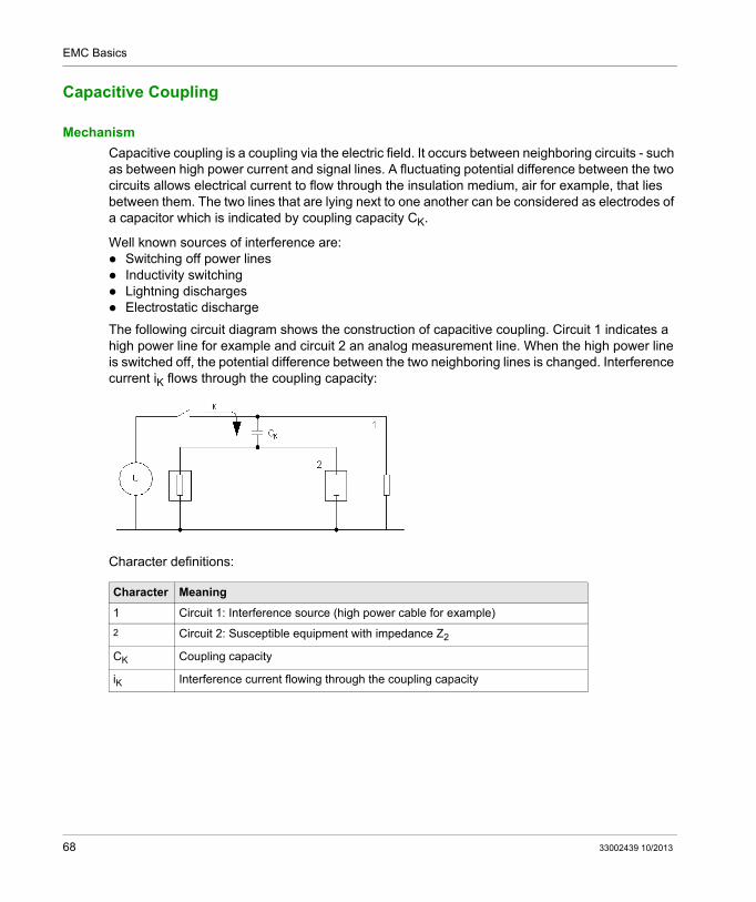
The following circuit diagram shows the construction of capacitive coupling. Circuit 1 indicates a high power line for example and circuit 2 an analog measurement line. When the high power line is switched off, the potential difference between the two neighboring lines is changed. Interference current iK flows through the coupling capacity:
Character definitions:
Character Meaning
1 Circuit 1: Interference source (high power cable for example)
2 Circuit 2: Susceptible equipment with impedance Z2
CK Coupling capacity
iK Interference current flowing through the coupling capacity
68 33002439 10/2013
EMC Basics
Size of the interference
The amount of interference current ISt caused by capacitive coupling depends on coupling
capacitance CK between the two conductors and the duration of the change in voltage du/dt on the
power cable.
The interference voltage created in the susceptible equipment (circuit 2) depends on:
NOTE: The interference voltage created in the susceptible equipment is proportional to the value of impedance in the susceptible equipment. And the impedance increases with the frequency of the interference signal. This results in the interrelationships.
High impedance measurement transfer lines are more susceptible to interference than low impedance circuits.
The interference current increases with the frequency of the voltage that exists in the interference capacity of the "connecting clamps".
High coupling capacitances create a short circuit between the circuits that influence one another for HF interferences.
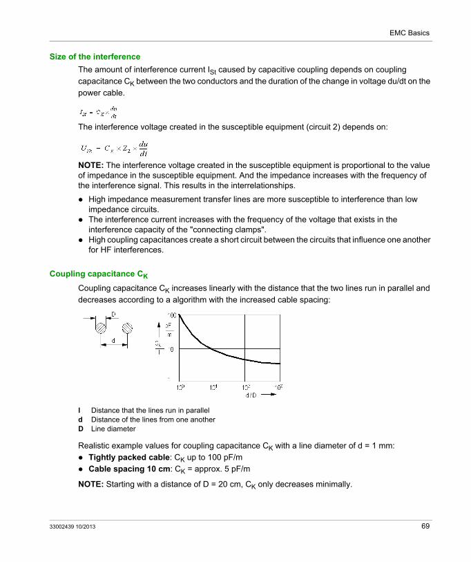
Coupling capacitance CK
Coupling capacitance CK increases linearly with the distance that the two lines run in parallel and
decreases according to a algorithm with the increased cable spacing:
l Distance that the lines run in paralleld Distance of the lines from one anotherD Line diameter
Realistic example values for coupling capacitance CK with a line diameter of d = 1 mm:
Tightly packed cable: CK up to 100 pF/m
Cable spacing 10 cm: CK = approx. 5 pF/m
NOTE: Starting with a distance of D = 20 cm, CK only decreases minimally.
33002439 10/2013 69
EMC Basics
Radiating Coupling
Mechanism
When system components are excited by electromagnetic waves having wave lengths of the measurements of these components, energy is radiated and is transferred across the electromagnetic field to the receivers. Antennas which can be made of loops, dipoles or single ground lines act as susceptible equipment.
Well known sources of interference are: Insufficiently shielded high frequency devices Radio and television Fluorescent lamps walkie-talkies, cellular telephones
Size of the interference
The intensity of the excitement and radiation depends on the ratio between measurement and wave length. The amount of received voltage can be estimated at:
Character definitions
NOTE:
The radiating coupling becomes interesting with interference signal frequencies of 30 MHz and higher.
The interference is at its strongest if the length of the "Antennas" are a multiple of the wave length.
Character Meaning
U0 Received voltage in the susceptible equipment
E0 Electrical field strength at the receiver
heff Effective antenna height
70 33002439 10/2013
EMC Basics
Wave Influence
Mechanism
Wave influence is the combination of capacitive and inductive coupling of parallel lines, if the wave lengths of the signals are within their measurements, i.e. with highly frequent signals.
A progressive wave which creates an electric field and a magnetic field is now the source of interference.
Current and voltage distribution on the line depend among other things on the following values: Wave resistance of the line Termination resistance of the line
Reflection of the signal occurs on the line or at the end if the wave resistance at the join is changed or if the wave resistance and the termination resistance are not the same size. The reflections override the incoming wave.
Lines within the range of the wandering fields are susceptible equipment. The coupling between the individual lines is done via the respective partial wave resistances.
Size of the interference
The amount of coupled interference voltage depends on the impedances of the disturbed lines. References for ratio calculations have been developed in conductor theory.
33002439 10/2013 71
EMC Basics
Which measures for which type of coupling?
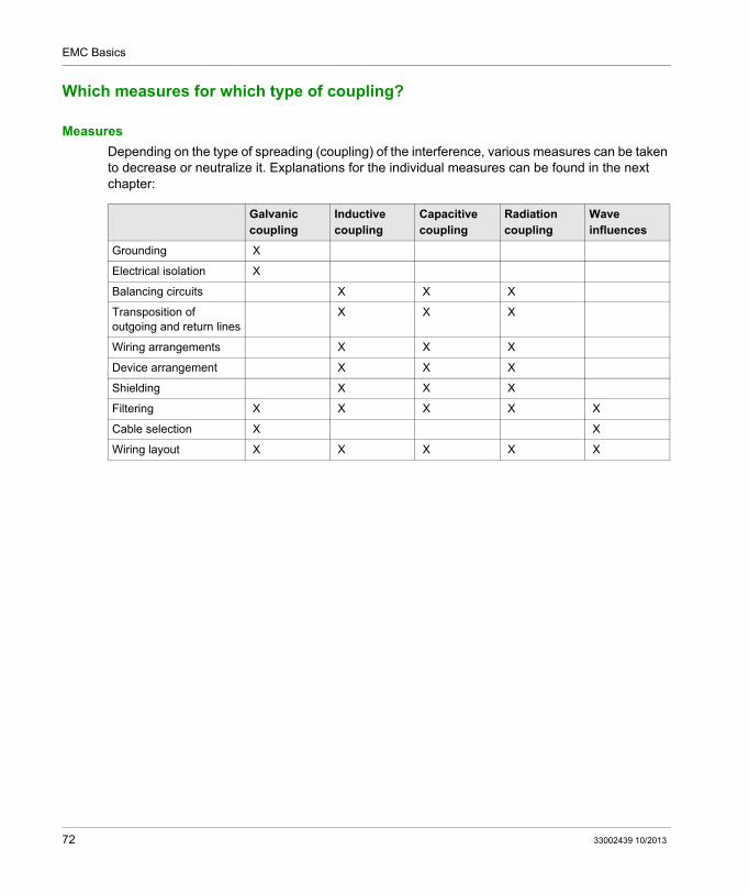
Measures
Depending on the type of spreading (coupling) of the interference, various measures can be taken to decrease or neutralize it. Explanations for the individual measures can be found in the next chapter:
Galvanic coupling
Inductive coupling
Capacitive coupling
Radiation coupling
Wave influences
Grounding X
Electrical isolation X
Balancing circuits X X X
Transposition of outgoing and return lines
X X X
Wiring arrangements X X X
Device arrangement X X X
Shielding X X X
Filtering X X X X X
Cable selection X X
Wiring layout X X X X X
72 33002439 10/2013
Grounding and Electromagnetic Compatibility of PLC Systems
EMC Measures
33002439 10/2013
Basic EMC Measures
Chapter 5Basic EMC Measures
Introduction
Using knowledge about sources of interference and coupling mechanisms, we have the following possibilities to reduce electromagnetic effects: Take measures against sources of interference that reduce the transmission of disturbance Take measures to limit the spreading of disturbance
This chapter provides detailed descriptions about basic measures to take against sources of interference, and measures to lessen their expansion (coupling).
You will need the information given in this chapter to understand EMC measures in a system and for EMC compatible design, and also to understand installation procedures.
A prerequisite for this chapter is knowledge about the types of sources of interference, the superposition of interference and useful signals and about coupling mechanisms.
What Is in This Chapter?
This chapter contains the following topics:
Topic Page
EMC Measures for Grounding Systems 74
EMC Compatible Wiring 77
Balancing Circuits 78
Transposition 79
Room Arrangements 80
Cabling Arrangements 81
Shielding 82
Filtering 84
33002439 10/2013 73
EMC Measures
EMC Measures for Grounding Systems
EMC functions of the grounding system
The grounding system has the following tasks with regard to EMC: Interference current dissipation Prevent couplings Maintaining shielding at specific potentials
The grounding system must fulfill these requirements without interfereing with the device and wiring.
NOTE: Green-yellow equipment grounding conductors are not usually suitable for these tasks. Grounding conductors can only dissipate low-frequency signals (50 ...60 Hz), and do not guarantee equipotential bonding for high-frequency signals as their impedance is too high.
Effect of grounding
The galvanic coupling is affected by the ground connection. Disturbances can spread via the grounding system across the entire plant if the grounding system is poorly configured or bad connections are made.
EMC measures for grounding systems
The following EMC arrangements are available for grounding systems: Optimal selection and combination of grounding systems (point-to-point or meshed) if
necessary Meshed grounding: sufficiently small surface area of the loop between exposed conductive
parts Sufficient cross-section of the earth conductors low-resistance and low-inductance lines and
therefore an effective equipotential bonding for low and high frequency signals Good chassis connection to decrease the contact resistance
Types of grounding systems
Two types of grounding systems are used: S Type: Point-to-point M Type: Grid-type
Large plants use both grounding types in combination as they have varying effectiveness depending on the application. The advantages and disadvantages of each system are described below.
74 33002439 10/2013
EMC Measures
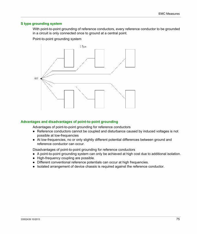
S type grounding system
With point-to-point grounding of reference conductors, every reference conductor to be grounded in a circuit is only connected once to ground at a central point.
Point-to-point grounding system
Advantages and disadvantages of point-to-point grounding
Advantages of point-to-point grounding for reference conductors Reference conductors cannot be coupled and disturbance caused by induced voltages is not
possible at low-frequencies At low-frequencies, no or only slightly different potential differences between ground and
reference conductor can occur.
Disadvantages of point-to-point grounding for reference conductors A point-to-point grounding system can only be achieved at high cost due to additional isolation. High-frequency coupling are possible. Different conventional reference potentials can occur at high frequencies. Isolated arrangement of device chassis is required against the reference conductor.
33002439 10/2013 75
EMC Measures
Grounding system type M
With grid type grounding, the reference conductors are connected multiple times to the chassis connection. This creates a meshed system.
The connections are arranged between the devices ground, cable runs, existing or under construction metal structures etc. Shielding, filtering devices return conductors, etc. are directly connected to this cable.
Grid-type grounding system
Advantages and disadvantages of meshed grounding
Advantages of meshed grounding for reference conductors Lower potential difference for high-frequency disturbance within the grounding system No isolated arrangement of device chassis is required against the reference conductor.
Disadvantages of meshed grounding for reference conductors Galvanic couplings between different circuits via common impedance and currents is possible
as a consequence of the induced voltage in the conductor loop.
76 33002439 10/2013
EMC Measures
EMC Compatible Wiring
Wiring rules
Electronic wiring must be done according to EMC compatibility. EMC measures include: Balanced construction and balancing of unbalanced coupled interferences Low input impedances Limited working frequency bandwidth Careful wiring arrangement Correct chassis connections Avoidance of internal couplings EMC domain management of power supplies
33002439 10/2013 77
EMC Measures
Balancing Circuits
Balancing
The purpose of balancing circuits is to convert unsymmetrical coupled interferences into symmetrical ones. Balanced interferences can therefore be suppressed by differential amplifiers.
See also: Overlapping of Interference and Useful Signals on Wires, page 53.
Wiring possibilities
The following wiring techniques can be used to balance circuits: Additional resistors Four conductor bundle Twisting wires Twisted
78 33002439 10/2013
EMC Measures
Transposition
Transposition
The transposition of outgoing and return conductors is done to suppress disturbance by creating
an inductive coupling in a circuit. Induced voltages in a successive conductor loops are 180o out of sync and neutralize each other.
Transposition becomes more effective with increasingly number of loops.
A good figure is 30 loops per meter.
33002439 10/2013 79
EMC Measures
Room Arrangements
Room arrangements from an EMC point of view
Arranging components in a room with regard to EMC basically means that a specified minimum distance between components must be maintained to avoid capacitive, inductive and radiation coupling. This results in groupings of sources of interference and susceptible equipment in a complete system. The field configuration is the decisive factor for the distances required.
80 33002439 10/2013
EMC Measures
Cabling Arrangements
The role of cables in EMC
Cables are used to transfer useful signals. At the same time they can also be an interference source or pass on disturbance they have received. All forms of coupling play a role here.
Principle of cable categories
Cables used in a system are categorized according to the type of signals they carry. The signals EMC performance is the deciding criterion.
You can roughly allocate cables into three categories or classes in an industrial environment: Sensitive signal Insensitive signal, low interference potential Signal is an active source of interference
Categorization allows cables with different EMC performance can be laid separately from each other.
There are the following options: Maintain distances between different categories Shield cables of different categories from each other
33002439 10/2013 81
EMC Measures
Shielding
Use of shields
Shielding is required if susceptible equipment and sources of interference cannot be sufficiently distanced through room rearrangements.
Shield
A shield is a metal component that is placed between the source of interference and the susceptible equipment. It influences the distribution between source and the equipment. The coupling is minimized this way.
Shielding types
There are several different types of shield that can be used: Cable shield Chassis as shield Room shielding Partition panel as shield
Shielding effectiveness
The effectiveness of the shield depends on its mutual impedance The mutual impedance must be as small as possible in order to achieve good shielding effectiveness.
The smaller the mutual impedance is, the greater the leakage current can be.
82 33002439 10/2013
EMC Measures
Mutual impedance of different cable shields
The following diagram shows the mutual impedance of different cable shields depending on the frequency:
Shield grounding
The shield is connected to ground to dissipate the currents. Sufficiently large cross sections are required for current dissipation since the current discharge can be very large with expanded plant systems.
Double shielding
Shielding can be improved by using double shielding. The additional shield is connected to ground at a suitable point.
Driven shield
Shielding can be improved by using a driven shield. This maintains the shield at the potential of the signal voltage.
You can achieve this for example, by back coupling a repeater output. This also means capacitive interference currents between the conductor and the internal shield are avoided.
33002439 10/2013 83
EMC Measures
Filtering
Filter
A filter comprises components such as capacitors, chokes or ferrite cores and are integrated in a circuit.
Filters should only let useful signals through and suppress undesired parts of the transferred signal as much as possible.
Filters are used for different purposes: To protect the power supply network against interference through the devices Protect devices from interference from the power supply network Protect circuits against interferences from devices within the circuit
How filters work
Useful signals and undesired signals are superposed at the filters input, only the useful signal is transferred to the output. The filtered out undesired signal is dissipated via the ground connection.
Filter types
There are the following filter types: Filter for common-mode interference Filter for differential mode disturbance Combined filter for differential and common-mode interferences
Ferrite cores
Ferrite cores are filters for high frequency common mode interferences. The are made from materials with high magnetic permeability.
Ferrite cores work on two principles: Inductivity against common interference currents Absorption of the induced high frequency interference current using simultaneous energy
release (warming up)
84 33002439 10/2013
Grounding and Electromagnetic Compatibility of PLC Systems
Guidelines for the Entire System
33002439 10/2013
Earth and EMC Measures in Automation Systems - System Guidelines
Part IIIEarth and EMC Measures in Automation Systems - System Guidelines
Introduction
This section contains guidelines for EMC and earth measures in automated systems. The measures are not product specific but generally apply to all modern systems and machines in which PLC systems are used.
What Is in This Part?
This part contains the following chapters:
Chapter Chapter Name Page
6 Measures for the Entire System 87
7 Grounding, Earthing and Lightning Protection System 91
8 Power Supply 109
9 Cabinets and Machines 113
10 Cabling 127
33002439 10/2013 85
Guidelines for the Entire System
86 33002439 10/2013
Grounding and Electromagnetic Compatibility of PLC Systems
Measures for the Entire System
33002439 10/2013
Measures for the Entire System
Chapter 6Measures for the Entire System
Introduction
This sections contains guidelines for EMC measures that apply to the entire system in which PLCs are used.
What Is in This Chapter?
This chapter contains the following topics:
Topic Page
Measures to take at Sources of Interference 88
Guidelines for Arranging Devices 89
Protection against Electrostatic Discharge 90
33002439 10/2013 87
Measures for the Entire System
Measures to take at Sources of Interference
Measures to take at Sources of Interference
Measures can be taken against sources of interference to suppress or reduce the interference at its origin.
Measures can include the following: Suppressing switched inductive loads Reducing the influence of electrostatic discharges Avoiding influence of walkie talkies Avoiding influence of low frequency magnetic fields Avoiding influence of electron torches
88 33002439 10/2013
Measures for the Entire System
Guidelines for Arranging Devices
Arrange devices in zones of differing disturbance climates
Zones of differing disturbances climates must be defined within the plant in which devices are arranged according to their sensitivity or potential for interference.
These include fundamentally different zones: Process Control system Data processing with computer work stations
PLC system
Separation of the PLC system is enabled by being installed in cabinets or on machine chassis. The guidelines for cabinet setups can be found in Guidelines for Arranging the Device in the Cabinet or a Machine, page 114.
Process
The processing plant with interfering components forms its own zone.
Sensitive cables and devices for process data acquisition and control (that are always in this zone) must be shielded.
Strong interference affects high current equipment above all through their magnetic fields, such as: High current equipment in energy supply company systems Melting in chemical plants Transformers Energy distribution from manufacturing plants
Computer work stations
Computer work stations should be placed in separate, shielded rooms that are equipped with close-mesh equipotential bonding in the floor, see Guidelines for the Grounding System in Buildings, page 94.
In reality, it is often necessary to install computer work stations near the production line. Monitors near high current equipment can have such large problems with interference that work is no longer possible with them.
If the magnetic fields present exceed the values recommended for monitor use, counter measures must be taken such as: Increase the distance from the source of the interference Shielding of the source of interference Use of plasma monitors Shielding of monitor screens
33002439 10/2013 89
Measures for the Entire System
Protection against Electrostatic Discharge
How electrostatic charge and discharge works
Computers, central control and operating devices are often installed in rooms with insulated flooring. Dry weather and low relative humidity lead to high electrostatic charge on the operating personnel that can lead to damaging discharges on devices: If you wear rubber soled shoes when walking across an insulated carpet of another material
(synthetics) an overcharge occurs on the soles of the shoes because two different insulated materials separate from each other.
Since the human body can be considered as conductive, an influence charge accumulates on the human body through the charged shoe soles, i.e. positive and negative charge carriers are separated. This charge accumulates with every step.
If metal objects or devices are now contacted, a discharge spark with a powerful current pulse is created, whereby the discharged energy is proportional to the square of the electrostatic charge.
Guidelines for protection against electrostatic discharges
Observe the following guidelines to avoid damage to operating equipment:
Use conductive flooring with a contact resistance between 105 and 109 Ohm. Do not treat smooth surfaces with wax, use anti-static cleaning products instead. Spray carpets with anti-static conditioners. Increase the relative humidity using a humidifier or air conditioning to a value above 50%.
90 33002439 10/2013
Grounding and Electromagnetic Compatibility of PLC Systems
Grounding, Earthing, Lightning Protection
33002439 10/2013
Grounding, Earthing and Lightning Protection System
Chapter 7Grounding, Earthing and Lightning Protection System
Introduction
This sections contains guidelines for the configuration of grounding, earthing and lightning protection systems in a plant in which PLC systems are used.
What Is in This Chapter?
This chapter contains the following topics:
Topic Page
Combination of Earthing, Grounding and Lightning Protection and Highest Safety Requirements
92
Guidelines for the Grounding System in Buildings 94
Guidelines for Local Grounding for Devices and Machines 96
Guidelines for Installing an Island Grounding System 97
Guidelines for the Earthing System and Grounding System 99
Guidelines for Lightning and Overvoltage Protection 101
Guidelines for Grounding and Earthing for Systems between Buildings 103
Guidelines for Creating Ground Connections 104
33002439 10/2013 91
Grounding, Earthing, Lightning Protection
Combination of Earthing, Grounding and Lightning Protection and Highest Safety Requirements
Overview
The earthing, grounding and lightning protection systems in a building must be designed together as they are always combined with each other.
The tasks of the three systems are as follows: Grounding system: The grounding system is responsible for ensuring an equipotential surface
for the plant. The connection of the grounding points with the earthing system means the grounding system has an important safety aspect.
Earthing system: The earthing system creates the electrical connection to earth that serves both as the equipotential bonding for the system and also for safety. Different safety and EMC requirements are required for the different system types TT, TN and IT systems.
Lightning protection system: The lightning protection system protects the plant and personnel against lightning strikes.
Highest safety regulations
The two following safety regulations must be observed when configuring the system: Personal injury must be avoided during normal operation and in the event of an error. This
means it must be avoided that people can come into contact with components that carry dangerous voltages. Dangerous voltages are: A.C. voltage with a peak value of 42.4 V and higher D.C. voltage of 60 V and higher.
In the event of differing safety and EMC requirements, the safety requirements must always have priority.
Safety before EMC!
NOTE: When configuring the earthing and grounding systems, always give safety requirements priority over EMC if the requirements are conflicting!
92 33002439 10/2013
Grounding, Earthing, Lightning Protection
Configuration example
The illustration shows an overview of how earthing, grounding and lightning protection systems can be implemented in a building while taking EMC into consideration:
33002439 10/2013 93
Grounding, Earthing, Lightning Protection
Guidelines for the Grounding System in Buildings
Grounding systems for expanded systems
We differentiate between a main grounding system that incorporates the entire plant and the local equipotential bonding for expanded systems: Main system grounding system: Grounding system that incorporates the entire building Local grounding system: Grounding system on the local level (device, machine, cabinet)
Guidelines for a building grounding system
EMC guidelines must be followed for the main grounding system in an expanded system within a building: Each floor must have an earth plane as well as a surrounding grounding strip.
This includes the following: welded, steel mats in the concrete bed, hollow floors with copper wire grids etc.
The distance between earth conductors must be greater than the following values: Production hall: 3 ... 5 m Areas with computers and sensitive measuring devices: < 2 m
All metallic structures within a building should be connected to the network. Metallic framework Concrete reinforcements welded together Metal piping Cable ducts Conveyor belts Metal door frames Grids ...
NOTE: Earth cables may not be longer than 10/(frequency in MHz). Earth cables that are too long cause undefined potentials in the system, unavoidably lead to potential differences between devices and allow undesired currents.
94 33002439 10/2013
Grounding, Earthing, Lightning Protection
Example: Earth plane in a building
The following illustration shows an example of EMC compatible installation of a grounding system in an industrial building
33002439 10/2013 95
Grounding, Earthing, Lightning Protection
Guidelines for Local Grounding for Devices and Machines
Local grounding
In addition to the grounding system for the entire system, expanded systems in a plant must also be equipped with local grounding for devices and machines to ensure a good equipotential bonding. The local grounding systems are connected to the plant grounding system.
Guidelines for local grounding
The following guidelines should be observed to achieve a good local equipotential bonding: An unbroken link (daisy chaining) should be made between all metal device and machine
structures: Switching cabinet Earth plane plate on cabinet floor Cable duct Pipe and sheathed cable lines Supporting components and metal chassis from machines, motors etc.
Special earth conductors may be required to complete the ground connection.Example: Both ends of a cable conductor which is not used are connected to ground.
The local ground connection must be connected to the main system network, whereby a maximum number of distributed ground connections should be made.
96 33002439 10/2013
Grounding, Earthing, Lightning Protection
Guidelines for Installing an Island Grounding System
Definition: Island grounding system
In an industrial environment the electrical equipment is usually grouped into specific areas or islands. A grounding system does not necessarily have to cover the entire building. Instead, the islands grouping together electronic equipment should be defined.
When electronic equipment is grouped into an area that is larger than approximately ten square
meters, a cage measuring 3 m2 to 5 m2 should be created by interconnecting the different grounding structures and enclosures.
A grounding cell is created by daisy chaining the grounding points. This can be cabinets, machine chassis and metallic cable ducts :
NOTE: Sensor and actuator cables outside of these islands must be shielded with great care!
33002439 10/2013 97
Grounding, Earthing, Lightning Protection
Example of daisy chaining
When equipment is grouped into several enclosures side by side, they are bolted together and thus make up an island. Two or more cabinets or machine chassis can be connected to an island by daisy chaining their grounding points.
Ground connections for cabinets and constructive components:
Guidelines and recommendations for island grounding systems
Recommendations for creating a grounding cell:
An island may not be larger than 3 ... 5 m2. "Conductive" false floors can be used to create an effective island grounding system. For
reasons of practicality only one of three supports needs to be connected. This gives you a cell
of 1.80 m2. The connections can be made using copper rod, short, fat bolts or with grounding strips. Where possible a direct positive fit contact should be made, for example, for the connection of
metal cable ducts. When two chassis or cabinets are installed side by side, they should be connected directly to
each other at at least two points, i.e. above and below. Ensure that paint or any other coating does not affect the electrical contact. The use of lock
washers is recommended. The cross-section of straps is not relevant since only their lenght is important. The grounding
connections must not exceed 50 cm.
98 33002439 10/2013
Grounding, Earthing, Lightning Protection
Guidelines for the Earthing System and Grounding System
Scope of the grounding system
The grounding system for an electrical system creates the connection to earth and must meet the following requirements: Discharge the voltage from touchable metallic system parts (chassis) to protect people from
electric shocks Discharge over-currents from direct lightning strikes to earth Discharge induced currents from atmospheric discharges between two points of a power
transmission line to earth
EMC performance and guidelines for the grounding system
System EMC performance Guidelines for use
TT Conditionally suitableBetween the ground connection of the primary distribution network and the leakage current from the electrical system, that are caused by ground faults within the system. As with transient currents, potential difference occurs due to the leakage current from devices. These transient currents can lead to faulty couplings or even faults within the system.A corrective measure here is a equipotential bonding conductor between the devices connected directly to earth. These measures basically convert the TT system into a TN-S system.
ELCB for personnel safety is required Surge arresters should be installed
(distributed over power transmission lines) This type of network requires corresponding
measures for devices with high leakage current potential that are located behind the ELCB in the outgoing direction
TN-CTN-C-S
BadBecause the functions and protective earth conductor are combined in TN-C and TN-C-S systems, current feedback occurs on the PEN conductors during normal operation. Current feedback from devices via the PEN conductors can lead to faulty couplings.
Ensure an unobstructed path for the PEN conductor when expanding the system!
Because of the high current in the PEN conductor this system is not permitted in areas of particularly dangerous sources.
If devices with high total harmonic distortion are operated in a system, this type of system is not recommended.
TN-S Very goodThe TN-S system is the best solution from an EMC point of view. The PE conductors have no power in normal operation.
Ensure an unobstructed path for the PE conductor when expanding the system!
A 500 mA ELCB must be installed for protection against fire.
Corresponding measures are required for devices with high leakage current potential that are located behind the ELCB in the outgoing direction.
33002439 10/2013 99
Grounding, Earthing, Lightning Protection
Recommended grounding system connection scheme
The following illustration shows a typical connection scheme for a grounding system:
o
A Lightning arrester down-leadB Underground meshed earthing system with reinforcement at foot of the down-leadC System ground connection, connected to the equipotential bonding strip, to which the PE conductor or PEN
conductor are connected in turnD Earthing system for a system section with integral metallic structures or additional ground connections (E)E Interconnection between the lightning arrester down-lead and the earthing system as well as other metal
structures in the vicinity
NOTE: A single, specifically laid ground connection is required for every electrical system and is in itself sufficient.
IT BadNote: The IT system is recommended as intrinsically safe for safety matters since no electric arcs can occur.
Ensure an unobstructed path for the PE conductor when expanding the system!
Filters for asymmetric interference currents cannot be installed.
Good EMC is only provided within systems (buildings) where all devices are connected to the same grounding device.
If circumstances dictate that the system must be divided to limit the cable lengths and leakage currents
System EMC performance Guidelines for use
100 33002439 10/2013
Grounding, Earthing, Lightning Protection
Guidelines for Lightning and Overvoltage Protection
Definition: External and internal lightning protection
We can make a differentiation between external and internal lightning protection for a building containing an electrical system:
External lightning protection: External lightning protection is the installation of air terminations that discharge the lightning current to the earth via a suitable earthing system.
Internal lightning protection, overvoltage protection: Internal lightning protection comprises measures taken against the effects of the lightning strike and its electrical and magnetic fields on metal installations and electrical systems. This means primarily the measures taken against equipotential bonding and overvoltage protection.
Guidelines for lightning protection
The following guidelines should be observed for lightning and overvoltage protection: The system should be divided into lightning protection zones with staggered protective
measures, see table below. All conductive parts that enter a zone should be connected to one another and with equipotential
bonding strip at the edges of the individual zones. The shielding for the zones should also be connected to these strips. In addition, a connection to equipotential bonding strips to higher and lower priority protection
zones.
NOTE: All lines going in and out of the system to be protected must be connected to the earthing system directly via spark gaps or protective devices (lightning arrestors). In the event of a lightning strike the potential of the system struck increases temporarily but no dangerous potential difference occurs within the system.
Lightning protection zones
Dividing the system into lightning protection zones with staggered protective measures is done as follows:
Zone Definition Measures
0 All objects are exposed to a direct lightning strike.
External lightning protection via surge arresters and down-leads to the earthing system
1 The objects are not exposed to direct lightning strikes, the magnetic field dampened depending on the shielding present.
Building shield (steel reinforcement)
2 and additional
zones(1)
The objects are not exposed to direct lightning strikes, the magnetic field is better dampened, dissipated currents are reduced further.
Room shield using steel mash matDevice shield (metal housing)Lightning conductor
1: If necessary, additional zones with further reduced currents and electromagnetic fields must be installed.
33002439 10/2013 101
Grounding, Earthing, Lightning Protection
The following illustration shows an example of the division of a building into lightning protection zones
102 33002439 10/2013
Grounding, Earthing, Lightning Protection
Guidelines for Grounding and Earthing for Systems between Buildings
Problems that arise with systems that encompass more than one building
A system is not always accommodated within one building, but can stretch across two or more buildings. This means there are power and/or signal cables going from one building to another.
If both buildings have independent ground connections and grounding systems, it can lead to an interfering potential difference between the end points of a line running between buildings.
In the event of a lightning strike on one of the buildings this potential difference can become so high that destructive transient currents can be sent down the line. People and animals can also be endangered if parts of the buildings can be touched simultaneously.
Guidelines for grounding and earthing between buildings
When a system is installed across more than one building the following guidelines for grounding and earthing must be observed: Earthed parts that can be touched simultaneously must be connected to the same earth
connection. A suitable potential compensation lead must be installed between the buildings grounding
systems that is capable of dissipating transient currents caused by lightning strikes.
NOTE: All lines going in and out of the system to be protected must be connected to the earthing system directly via spark gaps or protective devices (lightning arrestors). In the event of a lightning strike the potential of the system struck increases temporarily but no dangerous potential difference occurs within the system.
33002439 10/2013 103
Grounding, Earthing, Lightning Protection
Guidelines for Creating Ground Connections
Guidelines for a good ground connection
The following guidelines should be followed when creating ground connections: Ground connections must be made with great care and the operating demands of the system
must not be impaired. High contact resistance with the ground connection must be avoided by taking the following
measures: Galvanized mounting plates and fixing components must be used Remove painted or coatings from contact points and protect from corrosion with electrically
conductive special grease Bolt on metal pieces directly, without additional electrical conductors, e.g. cable ducts Daisy chaining of earth busbars and welded or bolted on grounding strips (instead of flexible
grounding cables)
Install earth busbars, grounding strips
Daisy chaining of earth busbars and welded or bolted on grounding strips (instead of flexible grounding cables)
104 33002439 10/2013
Grounding, Earthing, Lightning Protection
Example: Cabinet door
Use grounding strips instead of a flexible earth cable for the connection between the cabinet door and the cabinet housing
33002439 10/2013 105
Grounding, Earthing, Lightning Protection
Remove all coatings
Remove painted or coatings from contact points and protect from corrosion with electrically conductive special grease
106 33002439 10/2013
Grounding, Earthing, Lightning Protection
Direct bonding by bolted fastening for metallic parts
Bolt on metal pieces directly, without additional electrical conductors, e.g. cable ducts
33002439 10/2013 107
Grounding, Earthing, Lightning Protection
Ground connection for cable shields
The following illustration shows how to create a ground connection for cable shields.
NOTE: The ground connection for cable shields must always run through the entire cable.
108 33002439 10/2013
Grounding and Electromagnetic Compatibility of PLC Systems
Power Supply
33002439 10/2013
Power Supply
Chapter 8Power Supply
Introduction
This sections contains guidelines for the configuration and layout of the power supply for a system in which PLC systems are used.
What Is in This Chapter?
This chapter contains the following topics:
Topic Page
How to Plan the Power Supply Plant 110
Guidelines for the Power Supply 111
33002439 10/2013 109
Power Supply
How to Plan the Power Supply Plant
Potential disturbances in the power supply network
The power supply network can itself be the source of continuous and intermittent interference. Disturbances in the power supply can already be present in open networks at the entry to the system. Further disturbances can be introduced by devices in the system that are connected to the power supply.
Procedure for meeting technical specifications
Proceed as follows to create the technical specifications for the power supply:
Step Action
1 Categorize the potential upstream circuit disturbance (characteristics, strength, frequency).
2 Catalog the different devices to be powered as well as the types of disturbance created by them that can affect the functioning of the system.
3 Assess the effects of the disturbance on the system.
4 Evaluate the effects (are the consequences bearable?).
5 The evaluation of the effects of disturbances is then used to create the technical specifications for the power supply. This enables you to determine required properties of the electrical power supply to be installed.
110 33002439 10/2013
Power Supply
Guidelines for the Power Supply
General guidelines
The following guidelines should be observed regarding the power supply: A surge limiter must be installed at the junction where the flex enters the building. Disturbances to the mains power are dampened by industrial line filters installed at the entrance
to the system. Sensitive devices are protected by surge limiters and surge arresters at the input feed. Transformers can also be used as filters. For high frequency disturbances the transformer must
be equipped with single, or preferably double, shielding.
Example: Solution for the power supply
The following illustration shows an example of filtering the mains power by using a double isolated transformer:
NOTE: A good ground connection is vital when installing transformers. The transformer housing must be bolted to a conductive earth plane.
33002439 10/2013 111
Power Supply
Guidelines for partitioning in the system
The power supplies for the individual devices should be wired as point-to-point from the line entry:
Separate power supplies must be provided if extremely sensitive and high interference devices are used concurrently in the same power supply system:
Devices with high inference capabilities must be connected as close as possible to the line entry and sensitive devices connected at a distance from the line entry:
112 33002439 10/2013
Grounding and Electromagnetic Compatibility of PLC Systems
Cabinet
33002439 10/2013
Cabinets and Machines
Chapter 9Cabinets and Machines
Introduction
This section contains guidelines for the setup of cabinets from an EMC point of view, and for the installation of specific components.
Some of the guidelines are also applicable for machines that are equipped with PLC controllers, whereby the machine housing can be equated with cabinet housing.
What Is in This Chapter?
This chapter contains the following topics:
Topic Page
Guidelines for Arranging the Device in the Cabinet or a Machine 114
Guidelines for Grounding and Earthing in the Cabinet 117
Connections examples 119
Guidelines for the Reference Conductor System in the Cabinet 121
Guidelines for Cabling in the Cabinet 122
Guidelines for Materials and Lighting in the Cabinet 123
Guidelines for Installing Filters in the Cabinet 124
33002439 10/2013 113
Cabinet
Guidelines for Arranging the Device in the Cabinet or a Machine
EMC Domain
Sensitive and interfering electrical components and cables must be kept separate. This is possible by housing them in separate cabinets or by using shielded partition panels.
The cabinet must be divided into EMC domains: Areas of different interference levels (EMC domains) must be made in the cabinet. This means
that sources of interference and susceptible equipment must be kept separate. The EMC domains must be decoupled.
NOTE: For machines:
NC controllers, PLCs and drives can be installed in a cabinet or machine housing under the following circumstances: The drive cable must be shielded. The guidelines for cabling must be observed, see Cabling, page 127.
Isolation of Inductances
Isolation by using partition panels is necessary for the part of the cabinet where sources of inductance are mounted. The partition panel must have a good connection to the cabinet (ground).
Examples of such sources of inductance are: Transformers Valves Contactors
114 33002439 10/2013
Cabinet
Example: EMC domains separated by partition panels
Example for setting up small cabinets: partitioning using partition panels that are connected to ground at several points, reduces interference influences
33002439 10/2013 115
Cabinet
Solution: EMC domains in two cabinets
Example for setting up large cabinets: A separate cabinet is provided for the power and control sections; cable connections are made in a metal cable channel:
116 33002439 10/2013
Cabinet
Guidelines for Grounding and Earthing in the Cabinet
Guidelines for Earthing and Grounding in the Cabinet
The following guidelines should be observed when grounding a cabinet: An unpainted earth reference plane or rail must be installed on the floor of the cabinet for the
conventional reference potential. All metal parts of the cabinet are connected with each other. The metal housing of the cabinet must be integrated in the higher level earthing system. All protective grounding conductors must be earthed.
Constructing earth and ground in the cabinet
The following illustration shows how the earth and grounding system is constructed in the cabinet.
EB Adjacent cabinet or jigFE The functional earth, e.g. the iron beam of the hall, water or heating supply pipes, or neutral earthing for
the hallHS Mounting rail for installing the module backplane or the installation accessoriesM Reference conductor system or reference conductor rail (massive copper busbar or bridged terminal block)MA Grounding (earth reference plane or rail) that is used as the functional earthPE Protective earth PE, via protective earth choke
33002439 10/2013 117
Cabinet
Guidelines for installing a ground connection in the cabinet
In cabinets and machines, there are a lot of grounding structures which enable a maximum of protective effects.
The following guidelines should be observed when installing a ground connection in a cabinet: An unpainted earth reference plane or rail must be installed on the floor of the cabinet for the
common reference potential. The sheet or metal grid that acts as the earth reference plane or rail is connected to the cabinets
metal housing at several points that is integrated with the systems ground connection. All electrical components (filters etc.) are bolted directly to this earth reference plane or rail. All cables are fixed straight through this earth reference plane/rail. The all-around contact of the cable shield is created using locknuts that are bolted straight
through the earth reference plane/rail. All these electrical connections should be made with utmost care to achieve a low resistance
connection. Plastic cable ducts are permitted in enclosures if they are systematically mounted on the cage
at the back or on DIN rails that are themselves connected to the grounds in the enclosure. The design of enclosures means that many elements, including the doors, are only mounted at
particular points (using screws, welding, hinges, etc). This results in several gaps. Entry and exit of cables must be systematically located near these mounting points or duplicated by a grounding braid. This layout means the gap can be masked and the protective effects thus maintained.
For a shielded cable connection (see page 108), it is advised to use a fixed cross-panel screen connection via metallic compression gland. This solution is better than any other solution, providing that the paint is scraped off in order to ensure a good electrical contact. However, a jumper can also be used, to ensure contact over at least 180° .
NOTE: The way in which shielded cables are connected directly determines the HF protective effect. If the connection is made up using a "pigtail", that is, a single wire, protection is no longer provided at HF. Use of the "pigtail" is not recommended.
118 33002439 10/2013
Cabinet
Connections examples
Screw terminal block
When connecting to screw terminal blocks where use of a jumper for shielding connections is not possible, the pigtail must be as short as possible. This type of connection should be avoided.
The graph below shows the right way to do a screw terminal block connection :
33002439 10/2013 119
Cabinet
Connector
When using a connector, its design must ensure 360° electrical continuity between the cable shielding and the machine ground.
The graph below shows the right way to build a connector-type connection :
120 33002439 10/2013
Cabinet
Guidelines for the Reference Conductor System in the Cabinet
Reference conductor system
The cabinet contains different reference conductor systems that are connected to one another: An unpainted earth reference plane must be installed on the floor of the cabinet as the common
reference potential. The reference conductor system for the following areas must be separated from one another: Analog part (with point-to-point arranged reference conductors) Digital part (with meshed reference conductors) Power circuit (usually with point-to-point arranged reference conductors)
The galvanic coupling for the reference conductor system must be minimized.
Example: Reference conductor system
Example of partitioning the reference conductor system and its galvanic isolation:
33002439 10/2013 121
Cabinet
Guidelines for Cabling in the Cabinet
Guidelines for Cabling
The following guidelines apply when cabling the cabinet: As with external cabling, the cabling guidelines also apply to cables inside the cabinet, Cabling,
page 127. Conductive coupling between the interference current dissipation of filters and cable shields
with the reference conductor system must be avoided. For analog process signals, shielded twisted outgoing and return conductors should be
selected.
Guidelines for cable ducts in the cabinet
The following guidelines must be observed when running and combining cables in the cable ducts: 115/230 VAC mains and signal lines and 24/60 VDC signal lines must be laid in different cable
ducts. The distance between the ducts must be at least 100 mm. Unavoidable crossing must be at right angles.
Digital signal lines (24/50 VDC) may be unshielded in a common cable channel. The following cables can be combined in a cable duct: Shielded bus cable Shielded analog process signal cable Unshielded 24/60 VDC signal lines
Guidelines for installing cables
The following guidelines should be observed when installing cables in cabinets: The selection of the housing lead through must be made very carefully as this is the connection
with the earthing system. Interfering cables must be filtered before entering the cabinet.
Guidelines for filters
The following guidelines should be observed when using filters: The filter must have a good conductive ground connection. The filters input line may not be laid together with the filters output line or with other signal and
supply lines. When mounting the filter near a cable entrance (distance from floor or wall < 100 mm), the line
to the filter is only twisted. When mounting a filter further than 100 mm away from the cable entrance, the line through the
cabinet must be twisted and shielded.
122 33002439 10/2013
Cabinet
Guidelines for Materials and Lighting in the Cabinet
Guidelines for materials
Suitable metal combinations must be used to ensure a long term highly conductive connection between the metal parts that form the cabinet:
The metals to be connected should be selected according to the electro-chemical series of metals, to reduce the potential differences to a maximum of 0.5 V. This also applies when selecting the connection components such as screws, stay washers, rivets etc).
Guidelines for Lighting
Fluorescent tubes may not be used in series to light cabinets.
The following lights can be used: Light bulbs Energy saving lamps Fluorescent tubes with electronic starters
33002439 10/2013 123
Cabinet
Guidelines for Installing Filters in the Cabinet
Installation guidelines for filters
The effectiveness of an AC power supply filter is determined at HF by its mounting rather than by its electrical operation. The following guidelines should be observed when installing filters in a cabinet: Filter should be installed directly to the cable input in the cabinet if possible. Filters are screwed directly to the unpainted wall or to the earth reference plane on the base of
the cabinet. The upstream and downstream cables may not be installed in parallel. The upstream and downstream cables must be wired either side of the filter in order to limit the
cross coupling effect between the input and output. The filters cable must be wired directly across the cabinet wall or floor.
NOTE: Pay attention to leakage current from the filter! Special safety measures must be taken for leakage currents above AC 3.5 mA/DC 10 mA. Refer to the standards that apply in your country.
Example: Excellent Installation Locations
The following illustration shows two good solutions for installing a filter in a cabinet:
124 33002439 10/2013
Cabinet
Example: Filters Installation
The following illustration shows the proper solution for installing filters cables on the cabinet wall or floor:
33002439 10/2013 125
Cabinet
Example: Excellent Installation
The following illustration shows an excellent filter installation:
126 33002439 10/2013
Grounding and Electromagnetic Compatibility of PLC Systems
Cabling
33002439 10/2013
Cabling
Chapter 10Cabling
Introduction
This sections contains guidelines for cabling systems in which PLC systems are used.
What Is in This Chapter?
This chapter contains the following topics:
Topic Page
Classification of Signals according to their EMC Performance 128
Guidelines for Selecting Cables 129
Guidelines for Combining Signals in Cables, Conductor Bundles and Connectors 131
Guidelines for Laying Cables in Parallel and Crossing Cables 132
Guidelines for Creating the Ground Connection for Cable Shielding 133
Guidelines for Grounding Unused Conductors 135
Guidelines for Installing Cables 136
Guidelines for Cable Ducts 137
Guidelines for Cables between Buildings 140
33002439 10/2013 127
Cabling
Classification of Signals according to their EMC Performance
Reasons for the classification
In an industrial environment, signals are classified in four categories according to their EMC performance. This classification is required for the application of cabling rules.
Classification of signals
The following table shows the classification of signals according to their EMC performance:
Classification EMC performance Example of a circuit or device with cables in this class
Class 1Sensitive
Signal is very sensitive. Low level circuits with analog output, instrument transformer ...
Low-level digital circuits (bus ...) Low-level circuits with digital output, (instrument
transformer ...) Control circuit for resistive load Low-level d.c. power supplies
Class 3Slightly interfering
Signal disturbs class 1 and 2 cables
Control circuit for inductive loads (relay, contactor, coils, inverters ...) with corresponding protection
A.C. power supplies Main power supplies for high power devices
Class 4Interfering
Signal disturbs other classes signals
Welding machine Power circuits in general Electronic speed controller, switching power supplies ...
128 33002439 10/2013
Cabling
Guidelines for Selecting Cables
Guidelines for Selecting Cables
The following guidelines should be observed when selecting cables for use in an industrial environment: Use cables with twisted outgoing and return conductors. For analog signals, cables with shielded out and return conductors and braided shields should
be used.Use cables with double shielding for analog process signals outside of buildings.
For high frequency radiated interference (5-30 Mhz), use cables with braided shields. Use shielded cables for interfering signals (class 4); additional shielding by installing cables
through metal tubes or metal cable channels.
Example for class 1 signals
Example for the implementation of cables for class 1 signals (sensitive)
Example for class 2 signals
Example for the implementation of cables for class 2 signals (slightly sensitive):
33002439 10/2013 129
Cabling
Example for class 3 signals
Example for the implementation of cables for class 3 signals (slightly interfering):
Example for class 4 signals
Example for the implementation of cables for class 4 signals (interfering):
130 33002439 10/2013
Cabling
Guidelines for Combining Signals in Cables, Conductor Bundles and Connectors
Combination of signals in cables and conductor bundles
Only signals of the same class may be combined in a cable or conductor bundle.
Combination of signals in connectors
The same connector may not be used for signals from different classes.
Analog and digital signals can be combined in a connector if a row of pins with 0 V connections is present between them.
33002439 10/2013 131
Cabling
Guidelines for Laying Cables in Parallel and Crossing Cables
Guidelines for Parallel Cabling
The following guidelines should be observed for parallel cabling with signals of different classes: Unshielded cables with signals from different classes should only be installed over the shortest
distance possible. Parallel cabling of unshielded cables with signals from different classes should be installed with
the largest possible working clearance. Shielded cables should be used if cables with different signal classes are to be installed in
parallel over distances of more than 30 m, or if the working clearance can not be guaranteed.
Recommended working clearances
The following illustration shows the recommended working distances between shielded cables with signals from different classes for parallel installation up to 30 m. The longer the distance for the parallel cabling, the greater the working distance to be selected.
Guidelines for crossing cables
Cables that carry different class signals must cross at right angles.
132 33002439 10/2013
Cabling
Guidelines for Creating the Ground Connection for Cable Shielding
Guidelines for selecting the method of connection
NOTE: Always avoid cable shielding without a ground connection. This type of connection is practically useless from an EMC point of view and cannot be permitted for safety reasons if contact protection is not provided.
The table shows how the cable shield should be connected to ground depending on the application:
Long lines
For long shielded lines, several ground connections at intervals of 10 ... 15 m along the length of the cable are recommended:
Application Cable shield ground connection
Shielded analog measuring circuit in the cabinet Ground connections are usually found on one side of the cabinet outlet
Both ends of the cable shielding ground for extreme levels of disturbance
Shielded analog measuring circuits outside of cabinets in closed buildings
If only capacitive electrical interference is to be reckoned with: single cable shielding ground connection
If the signal line is setup with high-frequency influences: double sided cable shielding ground connection
If the signal line is long: in addition to double ground connections along the cable length, further ground connections at intervals from 10 ... 15 m
33002439 10/2013 133
Cabling
Characteristics of the connection methods
The shielding ground connection is very important for the shielding effectiveness. The following ground connection options have differing effectiveness:
Cable shield ground connection
Effectiveness and advantages Restrictions
Ground connection on both ends of the cableExtremely effective
Very effective against external disturbances (high and low-frequency)
Very good shielding effectiveness also against resonance frequency on the cable
No potential difference between cable and ground
Enables common laying of cables that feed different class signals
Very good suppression of high-frequency disturbances
Ground-fault current can be induced in high-frequency signals with high interference-field strength for long cables (>50 m).
Ground connection on only one end of the cableAverage shielding effectiveness
Enables protection of isolated lines (instrument transformer, ...) against low-frequency electric fields
Enables buzz to be avoided (= low-frequency disturbance)
Ineffective against external disturbances caused by high-frequency electric fields
The shielding can cause resonance due to the antenna effect. This means the disturbance is greater than when shielding is present!
Potential difference between the shielding and the ground connection at the unearthed end; danger in the event of contact!
Shielding without ground connectionNot recommended
Limits the capacitive coupling Ineffective against external disturbances (all frequencies)
Ineffective against magnetic fields Potential difference between the
shielding and the ground connection; Danger in the event of contact!
134 33002439 10/2013
Cabling
Guidelines for Grounding Unused Conductors
Guidelines for unused conductors
Free or unused cable conductors must be connected to ground at both ends.
The following illustration shows how unused conductors can be connected to ground.
33002439 10/2013 135
Cabling
Guidelines for Installing Cables
Avoiding loops between exposed conductive parts
To avoid loop between exposed conductive parts all cables must be installed near ground connections or ground cables.
The illustration shows an example of how cables are installed near ground connections:
Installing outgoing and return conductors next to each other
Outgoing and return conductors must always be installed close to each other.
The smallest possible intervals are guaranteed across the total run length by using 2-wire twisted wire cables.
The illustration shows how out and return conductors are installed closely next to each other. Parallel installation is only possible for signals of the same class.
136 33002439 10/2013
Cabling
Guidelines for Cable Ducts
Guidelines for arranging the cables in cable channels
Sensitive cables (classes 1 and 2) must be installed in the corners of the cable duct:
Guidelines for connecting cable ducts
Connecting cable ducts must be carried out when necessary i.e. direct bonding by bolted fastening.
NOTE: The earthing of cable ducts must be carried out when necessary, see Direct bonding by bolted fastening for metallic parts, page 107.
Non metallic cable ducts
NOTE: Cable ducts that are not electrically conductive such as PVC tubes, plastic skirting boards or similar, are not recommended as they offer no shielding. For example, they can be used in existing systems but only with a maximum run length of 3 m.
33002439 10/2013 137
Cabling
Recommended cable ducts
The following cable ducts are recommended:
Steel conduit Steel cable duct
Trunking Steel cable duct
Buried cable Cable tray or steel trays
138 33002439 10/2013
Cabling
Underground channel, closed Underground channel, open or ventilated
33002439 10/2013 139
Cabling
Guidelines for Cables between Buildings
Problems that can arise with outside cables
If signal cables are laid outside of buildings the following points should be noted: A potential difference can exist between buildings that can created an error during transfer. Cables between buildings can carry a higher current in the event of a sudden increase in the
potential of a building due to a lightning strike.
Guidelines for outside cables
For cables that are laid outside of buildings, the following guidelines should be observed: Shielded cables must be used. The shield must be capable of carrying the current and must be grounded at both ends.
If the shield cannot carry the current, a relieving line can be installed directly next to the signal cable for current dissipation. The relieving line should have a cross-section of approximately 35
mm2. Analog signal lines must have double shielded cables, the inside shield must be grounded at
one end and the outside shield at both ends. Signal lines must be wired with an over-voltage protection element, that is connected at the
cable entrance to the building when possible or at the cabinet as a minimum.
Observe the following: Guidelines for Grounding and Earthing for Systems between Buildings, page 103.
Recommended for data transfer between buildings
Fiber optic cables are recommended for data transfer between buildings. This creates no problems with loops between exposed conductive parts in the event of a lightning strike.
140 33002439 10/2013
Grounding and Electromagnetic Compatibility of PLC Systems
Quantum Family
33002439 10/2013
Quantum Family
Part IVQuantum Family
33002439 10/2013 141
Quantum Family
142 33002439 10/2013
Grounding and Electromagnetic Compatibility of PLC Systems
Quantum
33002439 10/2013
Quantum Family
Chapter 11Quantum Family
Introduction
This chapter contains product specific guidelines, installation instructions and information abut grounding and EMC for the components of the Quantum product family.
It contains the same information as the documentation provided with the products.
What Is in This Chapter?
This chapter contains the following topics:
Topic Page
Batteries as DC power supplies 144
General Information 145
AC Power and Grounding Considerations 147
DC Power and Grounding Considerations 151
Analog Grounding Consideration 157
Closed System Installation 163
33002439 10/2013 143
Quantum
Batteries as DC power supplies
Overview
Power Supplies usually provide the adequate isolation from high and low frequency RF noise because of filtered outputs. Batteries provide only good filtering abilities against low frequency noise.
To protect battery powered networks, additional RFI filters are required such as: CURTIS F2800 RFI filters TRI-MAG, Inc. FL Series Filters or equivalent
144 33002439 10/2013
Quantum
General Information
Overview
The required power and grounding configurations for AC powered and DC powered systems are shown in the following illustrations. Also shown are power and grounding configurations of AC and DC systems required for CE* compliance.
NOTE: Each rack shown has its own ground connection; that is, a separate wire returning to the main grounding point, rather than "daisy chaining" the grounds between power supplies or mounting plates.
The main grounding point is the local common connection of the panel ground, equipment ground, and earth grounding electrode.
CE Compliance
The CE mark indicates compliance with the European Directive on Electromagnetic Compatibility (EMC) (89/336/EEC) and the Low Voltage Directive (73/23/EEC).
NOTE: In order to maintain CE compliance, the Quantum system must be installed in accordance to these instructions.
Chassis Grounding
A chassis ground wire is required for each rack. The wire is connected between one of four ground screws (located on the rack) and the main ground point of the power system. This wire should be green (or green with a yellow stripe) and the AWG rating must be (at a minimum) sized to meet the fuse rating of the supply circuit.
DANGERELECTRIC SHOCK
The user is responsible for compliance with national and local electrical code requirements with respect to grounding of all equipment.Read, understand and implement the wiring and grounding requirements in this section.
Failure to follow these instructions will result in death or serious injury.
33002439 10/2013 145
Quantum
Power Supply Grounding
On each power supply connector there is a ground connection. The preferred connection is between the power supply connector ground terminal and one of the rack ground screws. This wire should be green (or green with a yellow stripe) and at a minimum the same AWG rating as the power connections to the supply.
In racks with multiple power supplies, each supply should have a ground connection between its input connector and the rack ground screws.
NOTE: It is recommended that the power supply, feeding the I/O modules, is grounded at the main ground point.
Other Equipment Grounding
Other equipment in the installation should not share the grounding conductor of the system. Each piece of equipment should have its own grounding conductor returning to the main grounding point from which the equipment power originates.
Systems with Multiple Power Feeds
In systems with multiple power feeds, the grounding should proceed in the same manner as single feed systems. However, a zero volt potential difference must be maintained between the equipment grounding conductors of the separate systems to prevent current flow on communication cables.
146 33002439 10/2013
Quantum
AC Power and Grounding Considerations
AC Powered Systems
NOTE: *AC N should be earth grounded. If it is not earth grounded, it must be fused (refer to local codes).
33002439 10/2013 147
Quantum
AC System with CE Compliance
NOTE: 140 CPS 111 00, 140 CPS 114 20 and 140 CPS 124 20 power supplies are designed to not require the external EMI filter, ferrite bead and Olflex cable.
NOTE: To maintain CE compliance with the European Directive on EMC (89/336/EEC), the AC power supplies must be installed per the European Directive on EMC (89/336/EEC).
NOTE: 140 XTS 001 00 and 140 XTS 005 00 connector models must be used in systems that must meet closed system requirements as defined in EN 61131-2 (without relying upon an external enclosure).
External Line Filters must be protected by a separate enclosure which meets the requirements of IEC 529, Class IP20.
148 33002439 10/2013
Quantum
Detail
The following figure shows the details of an AC powered system with CE compliance.
NOTE: Only one ground wire per rack is required. In redundant and summable systems, this lead is not connected for the additional line filter/power supply.
NOTE: For detailed wiring diagrams, refer to the part Power Supply Modules Power Supply Modules (see Quantum with Unity Pro, Hardware, Reference Manual)
33002439 10/2013 149
Quantum
Part List
Callout Vendor or equivalent
Part Number Description Instruction
1 Oflex-Series 100 cy 35005 Line Cord Terminate the shield at panel ground; the filter end of the shield is not terminated.
2 StewartFairite
28 B 0686-2002643665702
Ferrite Bead Install next to the filter and fasten with tie wraps at both ends of the ferrite bead.
3 Schaffner FN670-3/06 Line Filter (fast on terminals)Dimensions:Length:85 mm (3.4 in)Width: 55 mm (2.2 in)Height: 40 mm (1.6 in)Mounting Holes: 5.3 mm (0.2 in) diameter75 mm (3 in) centerline mounted.Fast on terminals: 6.4 mm (0.25 in)
Install next to the power supply.
4 NA NA Ground BraidFlat braid 134 mm (0.5 in) with a maximum length of 100 mm (4 in)
NA
5 Oflex Series 100cy 35005 Shield CableMaximum length: 215 mm (8.5 in)
Third lead (green/yellow) is not used; terminate the shield at the power supply ground terminal.
150 33002439 10/2013
Quantum
DC Power and Grounding Considerations
24 VDC Powered System Figure
The following figure shows a 24 VDC powered system.
NOTE: It is recommended to earth ground the 24 VDC power supply.
33002439 10/2013 151
Quantum
24 VDC Powered System for CE Compliance
The following figure shows a 3 A, 24 VDC powered system for CE compliance.
CAUTIONCE MARK NONCOMPLIANCE
The 140 CPS 211 00, the 140 CRA 211 20, and the 140 CRA 212 20 must be installed per the European Directive on EMC (89/336/EEC) and the Low Voltage Directive (73/23/EEC).
Failure to follow these instructions can result in injury or equipment damage.
152 33002439 10/2013
Quantum
24 VDC Detailed Figure
The following figure shows the detailed installation of a 3 A, 24 VDC powered system for CE compliance.
NOTE: For detailed wiring diagrams, refer to the part Power Supply Modules Power Supply Modules (see Quantum with Unity Pro, Hardware, Reference Manual)
Parts List.
Callout Vendor (or equivalent)
Part Number Description Instruction
1 Offlex Series 100cy 35005 Line Cord Terminate the shield at the power supply ground terminal
2 SrewardFairite
28 BO686-2002643665702
Ferrite Bead Install next to the filter and fasten with tie wraps at Both ends of the ferrite bead.
33002439 10/2013 153
Quantum
125 VDC Powered System Figure
The following figure shows a 125 VDC powered system for CE compliance.
CAUTIONCE MARK NONCOMPLIANCE
The 140 CPS 511 00 & the 140 CPS 524 00 must be installed per the European Directive on EMC (89/336/EEC) and the Low Voltage Directive (73/23/EEC).
Failure to follow these instructions can result in injury or equipment damage.
154 33002439 10/2013
Quantum
125 VDC Detailed Figure
The following figure shows the detailed installation for the 125 VDC powered system for CE compliance.
NOTE: For detailed wiring diagrams of power supply modules, refer to the part Part Power Supplies (see Quantum with Unity Pro, Hardware, Reference Manual)
Parts List.
Callout Vendor (or equivalent) Part Number Description Instruction
1 Offlex Series 100cy 35005 Line Cord Terminate the shield at the power supply ground terminal
2 SrewardFairite
28 BO686-2002643665702
Ferrite Bead Install next to the filter and secure with tie wraps at Both ends of the ferrite bead.
33002439 10/2013 155
Quantum
CAUTIONEUROPEAN COMPLIANCE
The 140 CPS 511 00 & the 140 CPS 524 00 must be installed per the European Directive on EMC (89/336/EEC) and the Low Voltage Directive (73/23/EEC).
Failure to follow these instructions can result in injury or equipment damage.
156 33002439 10/2013
Quantum
Analog Grounding Consideration
Overview
For the Analog Input Modules (see Quantum with Unity Pro, Discrete and Analog I/O, Reference Manual), the earthing must be done by the analog wires. Analog wires must be grounded directly when entering the cabinet. You may use an analog cable grounding rail. This section describes this approach.
Principle
High frequency interference can only be discharged via large surfaces and short cable lengths.
Guidelines
Follow these wiring guidelines: Use shielded, twisted-pair cabling. Expose 2.5 cm (1 inch) as shown:.
Make sure the wire is properly grounded (connection between the grounding bar and the clamps).o
NOTE: It is strongly recommended to use the STB XSP 3000 grounding kit and, either the STB XSP 3010 or the STB XSP 3020 clamp kits.
33002439 10/2013 157
Quantum
Assembly of the STB XSP 3000 Kit
The followed kit is used to have a high quality of the analog signal.
The following table describes the STB XSP 3000 grounding kit.
The following table describes the step to assemble the STB XSP 3000 grounding kit:
Elements Description
Side Supports and grounding bar
The following illustration describes the assembly of the side supports and the grounding bar.
158 33002439 10/2013
Quantum
Step Description
1 Push the side supports against the walls and tighten the screws.
2 Choose the length of the grounding bar.
33002439 10/2013 159
Quantum
3 Insert the functional grounding terminal block and tighten the screw
4 Fix the grounding bar at the side supports.
Step Description
160 33002439 10/2013
Quantum
STB XSP 3010 Kit and STB XSP 3020
The following table describes the different cable sections (in AWG and mm2):
5 The following figure describes the final assembly of the STB XSP 3000.
Step Description
Reference AWG mm2
STB XSP 3010 16 to 9 1.5 to 6.5
STB XSP 3020 10 to 7 5 to 11
33002439 10/2013 161
Quantum
Final Assembly
The following figure shows the final assembly:
162 33002439 10/2013
Quantum
Closed System Installation
Overview
For installations that must meet closed system requirements as defined in EN 61131-2 (without relying upon an external enclosure) in which an external line filter is used, it must be protected by a separate enclosure that meets the requirements of IEC 529, Class IP20.
AC/DC Installation
The following figure shows an AC/DC powered systems that meets CE closed system compliance.
* Only one ground wire per rack is required. In redundant and summable systems, this lead is not connected for the additional line filter/power supply
** Connectors 140 XTS 005 00 (for power supplies) and 140 XTS 001 00 (for I/O modules) must be ordered separately
NOTE: For detailed wiring diagrams, refer to the part Power Supply Modules Power Supply Modules (see Quantum with Unity Pro, Hardware, Reference Manual)
33002439 10/2013 163
Quantum
Protective Cover
The protective cover must completely enclose the line filter. Approximate dimensions for the cover are 12.5 x 7.5 cm. Wire entry/exit shall be through strain relief bushings.
Line Filter Connections
164 33002439 10/2013
Grounding and Electromagnetic Compatibility of PLC Systems
Momentum Family
33002439 10/2013
Momentum Family
Part VMomentum Family
33002439 10/2013 165
Momentum Family
166 33002439 10/2013
Grounding and Electromagnetic Compatibility of PLC Systems
Momentum
33002439 10/2013
Momentum Family
Chapter 12Momentum Family
Introduction
This chapter contains product specific guidelines, installation instructions and information about grounding and EMC for the components of the Momentum product family.
It contains the same information as the documentation provided with the products.
What Is in This Chapter?
This chapter contains the following topics:
Topic Page
Structuring Your Power Supply System 168
Selecting Power Supplies 169
Single Power Supply Configuration 170
Protective Circuits for DC Actuators 172
Protective Circuits for AC Actuators 174
Suggested Component Values for AC and DC Actuators 175
Grounding Momentum Devices 176
Grounding DIN Rail Terminals and Cabinets 178
Grounding Analog I/O Lines 179
33002439 10/2013 167
Momentum
Structuring Your Power Supply System
Overview
This section contains guidelines for planning and wiring your power supply system.
Use Separate Power Supply for Outputs
Operating voltage and input voltage can be derived from one power supply (PS). We recommend that the output voltage be drawn from a separate power supply (e.g., 10 A or 25 A, referred to as PS1 and PS2).
A separate output voltage supply prevents interferences caused by switching processes from affecting the voltage supply to the electronics. Where larger output currents are involved, provide additional power supplies for the output voltage (PS3, ...).
Use Star Configuration
Each I/O base should be fed by the power supply in star configuration, i.e., separate leads from the power supply to each module.
Avoid Induction Loops
Do not create any induction loops. (This can be caused by laying out the supply conductors L+/M-, ... in pairs.) As a remedy, use twisted-pair wiring.
Avoid Series Connections
The series connections often found in automatic circuit breakers should be avoided since they increase the inductive component in the output-voltage leads.
Potential-Isolated Fieldbus Islands
The potential relationships of the bus adapters are designed so that the individual I/O stations form potential-isolated islands (e.g., by isolating the incoming remote bus of InterBus). To decide whether potential balancing is necessary, refer to the installation guidelines of the used communication adapter.
CAUTIONPOTENTIAL FOR SHORT CIRCUITS AND/OR POWER-UP/POWER-DOWN SPIKES
Provide external fuses on the operating voltage to protect the module. Appropriate fuse values are shown in the wiring diagrams. An unprotected module may be subject to short circuits and/or power-up/power-down spikes.
Failure to follow these instructions can result in injury or equipment damage.
168 33002439 10/2013
Momentum
Selecting Power Supplies
Overview
This section provides guidelines for selecting power supplies.
Using Three-Phase Bridges
Unfiltered three-phase bridges can be used in 24 VDC power supplies for the I/O bases, the sensors, and the actuators. In view of the maximum permissible ripple of 5%, monitoring for phase failure is necessary. For single-phase rectification, the 24 VDC must be buffered to ensure conformance to the specifications in System Specifications (see Modicon Momentum I/O Base, User Guide) (20...30V; max. ripple 5 %).
Provide Reserve Capacity
Startup transients, extra long cables, and low cross-sectional efficiency can lead to voltage supply breakdowns. Therefore, you should select power supplies with enough reserve capacity and select the proper cable lengths and cross sections.
CAUTIONRISK OF ELECTRICAL SHOCK
Do electrically isolate the AC-to-DC converter between the input (primary) and output (secondary). Otherwise, voltage levels can be propagated to the output if the AC-to-DC converter fails.
Failure to follow these instructions can result in injury or equipment damage.
33002439 10/2013 169
Momentum
Single Power Supply Configuration
Overview
This section contains illustrations of a sample circuit layout, potential bundling, and potential isolation for a single power supply configuration.
Fusing in Circuit Layout
Each of the following circuit branches must be fuse-protected (F in the figure below). In the case of long lines, the circuit branch must be provided with a suppressor circuit OVP 001/OVP 248. This protection selectively shuts off a circuit branch through the associated fuse even if the diode is short-circuited.
Illustration
The following illustration shows a sample circuit layout for a single power supply configuration.
F automatic circuit breaker or fuse (see appropriate field wiring illustration in I/O base description)F10 optional circuit breaker (with over-voltage protection)PS power supply 24 VDC, max. 25 AV1 overvoltage protection circuit OVP 001, OVP 002
Fusing in Wiring Illustrations
The fuses shown in the illustrations below must be selected on the basis of the type and number of the sensors and actuators used.
170 33002439 10/2013
Momentum
Potential Bundling
In this example, the output voltage is drawn from a separate power supply.
Potential Isolation
In this example, the output voltage is drawn from a separate power supply
33002439 10/2013 171
Momentum
Protective Circuits for DC Actuators
Overview
This section discusses specific cases when inductive loads at output points require additional protective circuits (directly on the actuator) and provides two examples of protective circuitry.
Case 1
When there are contacted circuit elements (e.g. for safety interlocks) in the output conductors.
Case 2
When the leads are very long.
Case 3
Where inductive actuators are operated via relay contacts of the I/O base (to extend contact life and for EMC considerations).
Protective Circuit Types
In all three cases, the protective circuit is a clamping diode.
The following table provides generic selection guidelines.
Consult relay and contactor manufacturers’ catalogs for commercial suppression devices matched to your particular products.
Type of Load Suppression Device Minimum Component Rating
DC circuits a reverse-biased clamping diode across the load
2 A and greater than twice the maximum load voltage
172 33002439 10/2013
Momentum
Example 1
An example of a protective circuit for inductive DC actuators is illustrated below:
K1 contact, e.g., for safety interlocksV1 clamping diode as the protective circuit
Example 2
Another example of a protective circuit for inductive DC actuators is illustrated below:
V2 clamping diode as the protective circuit
33002439 10/2013 173
Momentum
Protective Circuits for AC Actuators
Overview
To reduce noise potentials and for EMC considerations you may need to equip the inductive actuators with noise suppressors, e.g., anti-interference capacitors, at the point of interference.
Protective Circuit Types
The following table provides generic selection guidelines.
Consult relay and contactor manufacturers’ catalogs for commercial suppression devices matched to your particular products.
Example
An example of a protective circuit for inductive AC actuators is illustrated below:
Type of Load Suppression Device Minimum Component Rating
AC circuits 50 Ω resistor in series with a 0.47 μfd nonpolarized capacitor across the load
for 120 VAC-powered loads 200 VAC
for 220 VAC-powered loads 400 VAC
174 33002439 10/2013
Momentum
Suggested Component Values for AC and DC Actuators
Suggested Values Only
The clamping diode forward current rating must be equal to or greater than load current. Diode PIV rating must be three or four times greater than supply voltage at 24 VDC and 8 ... 10 times greater than supply voltage at 110 VAC. The unpolarized (AC) snubb
Values may be:
Snubber resistors may be 1 ... 3 Ohms, 2 W. Resistor values should be increased up to 47 Ohms/5 W for RL exceeding 100 Ohms.
Load Inductance Capacitance
25 ... 70 mH 0.50 microF
70 ... 180 mH 25 microF
180 mH 10 microF
33002439 10/2013 175
Momentum
Grounding Momentum Devices
Overview
This section describes how to provide two types of grounding for assembled Momentum devices: functional earth (FE), used to discharge high frequency disturbances, guaranteeing proper EMC
behavior protective earth (PE), used to protect against personal injuries according to IEC and VDE
Grounding Momentum Devices
Momentum devices consist of an I/O base assembled with a communications adapter or a processor adapter and possibly an option adapter. The PE of the adapters is electrically connected with the PE of the I/O base; you do not have to provide any further grounding of the adapter.
Grounding Guidelines
Follow these guidelines. Be sure you establish good ground contacts. Connect the grounding screw to protective earth (PE) for AC and DC modules with a
recommended maximum torque of 4.4 in/lb (0.5 Nm) using a PZ2 driver.
Cable Specifications
When you are using ground cable up to 10 cm (4 in) long, its diameter should be at least 12 AWG
(or 2.5 mm2). When longer cables are used, larger cable diameters are required, as shown in the following illustration.
176 33002439 10/2013
Momentum
Grounding Scheme
The illustration below illustrates properly grounding modules and tracks.
1 grounding clamp, such as EDS 0002 cable grounding rail (CER 001), an optional component for grounding lines close to PE/FE rail3 PE/FE rail in the cabinet or PE/FE screw in terminal cabinet
NOTE: The lower DIN rail shows a cable grounding rail (CER 001), an optional component for grounding analog lines. For a procedure for grounding analog I/O lines, see Grounding Analog I/O Lines (see page 179).
33002439 10/2013 177
Momentum
Grounding DIN Rail Terminals and Cabinets
Overview
This section shows how to ground DIN rail terminals and cabinets.
Illustration
The following illustration shows how to ground DIN rail terminals and cabinets:
1 DIN rail for connecting the Momentum device and its accessories2 reference conductor system or rail (solid copper or connected terminals)3 grounding bar in the cabinet4 next cabinet5 grounding screw (PE/FE) in cabinetFE functional earthPE protective earthXY protective earth choke* conductor cross section depends on the load of the system
178 33002439 10/2013
Momentum
Grounding Analog I/O Lines
Overview
Analog wires must be grounded directly when entering the cabinet. You may use commercial cleats or clamps or an analog cable grounding rail. This section describes both approaches.
Principle
High frequency interference can only be discharged via big surfaces and short cable lengths.
Guidelines
Follow these wiring guidelines: Use shielded, twisted-pair cabling Expose the shielding on one side (for instance, at the console exit) Make sure the track is properly grounded (see page 176)
Grounding of the bus cable is determined by the bus adapter used. Look for details in your bus adapter manual.
Using Cleats or Clamps
Cleats or clamps can be mounted directly on the ground rail (PE/FE rail) in the cabinet, as shown in the illustration below. Be sure the cleats or clamps make proper contact.
33002439 10/2013 179
Momentum
180 33002439 10/2013
Grounding and Electromagnetic Compatibility of PLC Systems
Premium Family
33002439 10/2013
Premium Family
Part VIPremium Family
Introduction
This chapter contains product specific guidelines, installation instructions and information about grounding and EMC for the components of the Premium product family.
It contains the same information as the documentation provided with the products.
What Is in This Part?
This part contains the following chapters:
Chapter Chapter Name Page
13 Standards Conformity and EMC Characteristics 183
15 Power Supply for the Process and AS-i TSX SUP 205
16 Discrete I/O Modules TSX DEY/DSY 221
17 Safety Modules TSX PAY 233
18 Counter Modules TSX CTY 239
19 Axis Control Modules TSX CAY 247
20 Stepper Motor Control Modules TSX CFY 249
21 Electronic Cam Module TSX CCY 1128 255
22 Analog Modules TSX AEY/ASY 269
23 Weighing Module TSX ISPY100/101 271
33002439 10/2013 181
Premium Family
182 33002439 10/2013
Grounding and Electromagnetic Compatibility of PLC Systems
Standards Conformity and EMC Characteristics
33002439 10/2013
Standards Conformity and EMC Characteristics
Chapter 13Standards Conformity and EMC Characteristics
Introduction
This section provides an overview of the standards that Premium Hardware Products conform to, and also includes EMC standards. It also includes exact information about the products disturbance immunity and emitted disturbance.
What Is in This Chapter?
This chapter contains the following topics:
Topic Page
Standards and Certification 184
Operating conditions and environmental conditions to be avoided 185
33002439 10/2013 183
Standards Conformity and EMC Characteristics
Standards and Certification
General
Premium and Atrium PLCs have been developed to conform to the principal national and international standards for industrial electronic PLC equipment.
Programmable PLCs: specific requirements: functional characteristics, resistance, safety etc.IEC 61131-2, CSA 22.2 N° 142, UL 508
Merchant navy requirements of the major international organizations:ABS, BV, DNV, GL, LROS, RINA, RRS, CCS etc.
Adhering to European Directives:Low Voltage: 73/23/EEC amendment 93/68/EECElectromagnetic Compatibility: 89/336/EEC amendments 92/31/EEC and 93/68/EEC
Electric qualities and self-extinguishability of insulating materials: UL 746C, UL 94 Danger Zones Cl1 Div2 CSA 22.2 N° 213
DANGERRISK OF ELECTRIC SHOCK, EXPLOSION
Do not disconnect while circuit is live unless area is known to be non-hazardous.
This equipment is suitable for use in class i, division 2,Groups a, b, c and d or non-hazardous locations only.
Failure to follow these instructions will result in death or serious injury.
184 33002439 10/2013
Standards Conformity and EMC Characteristics
Operating conditions and environmental conditions to be avoided
Operating temperature/hygrometry/altitude
Data table:
Power supply voltages
Data table:
(1) Possible up to 34 VDC, limited to 1 hour every 24 hours.
For TSX PSY 1610 and TSX PSY 3610 power supplies, and when using relay output modules, this scope is reduced to 21.6V...26.4V.
Ambient temperature when operative
0° C to +60° C (IEC 1131-2 = +5° C to +55° C)
Relative humidity 10% to 95% (without condensation)
Altitude 0 to 2000 meters
Voltage nominal 24 VDC 48 VDC 100 to 240VAC 100...120/200...240 VAC
limit 19 to 30 VDC 19...60VDC (1) 90 to 264 VAC 90 to 140/190 to 264VAC
Frequency nominal - - 50/60 Hz 50/60 Hz
limit - - 47/63 Hz 47/63 Hz
Brown-outs duration ≤ 1 μs ≤ 1 μs ≤ 1/2 period ≤ 1/2 period
repetition ≥ 1 s ≥ 1 s ≥ 1 s ≥ 1 s
Harmonic rate - - 10% 10%
Residual ripple included
5% 5% - -
33002439 10/2013 185
Standards Conformity and EMC Characteristics
Human and material safety
Data table:
NOTE: The devices must be installed and wired according to the directions in the TSX DG KBL• manual.
Resistance of devices to power supply L.F. turbulence
Enclosures for protection * IEC 61131-2CSA 22-2 N° 142IEC 60950
IP 20
Impact Resistance CSA 22-2 N° 142IEC 60950
Drop / 1.3 m / 500 g Sphere
Legend
*: Tests required by EC directives
Test Designation Norms Levels
Voltage and frequency Variation * EN 50082-1 Un 15% / Nf 5% 30 min x 2Un 20% / Nf 10% 5 s x 2
Continuous voltage variation * EN 50082-1 0.85 Un - 1.2 Un 30 + 30 min+ 5% ripple maximum
Harmonic 3 * IEC 61131-2 10% Un0° / 5 min - 180° / 5 min
Legend
Un: Nominal Voltage Nf: Nominal Frequency Ud: Power-on detection level
*: Tests required by EC directives
186 33002439 10/2013
Standards Conformity and EMC Characteristics
NOTE: The devices must be installed and wired according to the directions in the TSX DG KBL• manual.
Resistance to H.F. turbulence
Data table:
NOTE: The devices must be installed and wired according to the directions in the TSX DG KBL• manual.
Momentary Interruptions * IEC 61131-2 AC 10 msDC 1 ms
Voltage peaks and troughs * IEC 61131-2 Un-0-Un; Un / 60s 3 cycles separated by 10 sUn-0-Un; Un / 5s 3 cycles separated by 1 to 5 sUn-0.9-Un; Un / 60s 3 cycles separated by 1 to 5 s
Test Designation Norms Levels
Legend
Un: Nominal Voltage Nf: Nominal Frequency Ud: Power-on detection level
*: Tests required by EC directives
Test Designation Norms Levels
Amortized oscillatory wave *
IEC 61131-2IEC 61000-4-12
AC / DC 1 kV SM24 V Discrete I/Os 1 kV SM
Fast transients (bursts) * EN 50082-1IEC 61000-4-4
AC / DC Power Supply 2 kV WM / CM48 V > Discrete I/Os 2 kV CMother ports 1 kV CM
Hybrid shockwave IEC 61000-4-5 AC / DC Power Supply 2 kV WM / 1 kV SMAC Discrete I/Os 2 kV WM / 1 kV SMDC Discrete I/Os 2 kV WM / 0.5 kV SMShielded Cable 1 kV CM
Thermal shocks whilst inoperative IEC60068-2-14 Na -25° C; -70° C / 2 Cycles: 3 o’clock - 3 o’clock
Test Designation Standards Levels
Flat free drop IEC60068-2-32 Ed 10 cm / 2 drops
Free drop from controlled position IEC60068-2-31 Ec 30° or 10 cm / 2 drops
Random free drop (conditioned material) IEC60068-2-32 Method 1
1 m / 5 drops
33002439 10/2013 189
Standards Conformity and EMC Characteristics
190 33002439 10/2013
Grounding and Electromagnetic Compatibility of PLC Systems
Basic elements
33002439 10/2013
Basic elements: Backplane TSX RKY, power supply TSX PSY
Chapter 14Basic elements: Backplane TSX RKY, power supply TSX PSY
Introduction
This section contains guidelines and information for the configuration and installation of the basic elements of the Premium hardware with regard to grounding and EMC.
What Is in This Chapter?
This chapter contains the following topics:
Topic Page
Connection of the ground to a TSX RKY rack 192
How to mount processor modules 193
Precautions to be taken when replacing a PCX 57 processor 195
Rules for connecting TSX PSY supply modules 196
Connecting alternating current power supply modules 198
Connecting direct current power supply modules from an alternating current network 200
33002439 10/2013 191
Basic elements
Connection of the ground to a TSX RKY rack
Grounding racks
Functional grounding of the racks is provided by the back, which is made of metal.
This means that the PLCs will be guaranteed to conform to environmental norms; assuming, however, that the racks are fixed to a metal support that is correctly connected to ground. The different racks which can make up a TSX P57/TSX H57 PLC station must be mounted either on the same support or on different supports, as long as the latter are correctly interlinked.
Illustration:
NOTE: The PLC’s internal 0V is linked to the ground connection. The ground connection itself being linked to ground.
DANGERELECTRIC SHOCK - IMPROPER GROUNDING
Each rack’s grounding terminal must be linked to the protective ground. Use a green/yellow wire with a minimum section of 2.5 mm (12 AWG) and with the shortest
length possible. Maximum torque on the ground connection screw: 2.0 N.m (1.5 lb-ft). Install to confrom to all local and national codes.
Failure to follow these instructions will result in death or serious injury.
192 33002439 10/2013
Basic elements
How to mount processor modules
Introduction
NOTE: Mounting and removing processor modules is otherwise identical to mounting and removing other modules.
when extracting/inserting modules with the power on, the terminal block or HE10 connector must be disconnected. You must also take care to shut off the sensor/pre-actuator supply.
Installing a processor module onto a rack
Carry out the following steps:
NOTE: the mounting of processor modules is identical to the mounting of other modules.
NOTE: Maximum tightening torque: 2.0 Nm (1.5 lb. ft.)
NOTICEPLC MODULE DESTRUCTION
Switch off the rack power supply before mounting a processor module.
Failure to follow these instructions can result in equipment damage.
Step Action Illustration
1 Place the pins at the back of the module into the centering holes on the lower part of the rack (number 1, see diagram 1).
2 Swivel the module to bring it into contact with the rack (number 2).
3 Fix the processor module to the rack by tightening the screw on the upper part of the module (number 3).
33002439 10/2013 193
Basic elements
Grounding modules
Processor modules are grounded using metal plates at the rear of the module. When the module is in place, these metal plates are in contact with the metal of the rack. This ensures the link with the ground connection.
Illustration
NOTICEPLC MODULE DESTRUCTION
Switch off the rack power supply before mounting a processor module.
Failure to follow these instructions can result in equipment damage.
194 33002439 10/2013
Basic elements
Precautions to be taken when replacing a PCX 57 processor
Important
WARNINGUNEXPECTED EQUIPMENT OPERATION
If the PCX P57 processor is being replaced by another processor which is not blank (the processor has already been programmed and contains an application), the power for all the PLC station’s control units must be switched off.
Before restoring power to the control units, check that the processor contains the required application.
Failure to follow these instructions can result in death, serious injury, or equipment damage.
33002439 10/2013 195
Basic elements
Rules for connecting TSX PSY supply modules
General points
The TSX PSY ••• power supply modules on each rack are equipped with a non-removable terminal block, provided with a cover, which is used to connect the power supply, the alarm relay, the protection ground and, for alternating current supplies, the supply of the 24 VDC sensors.
This screw terminal block is equipped with captive clamp screws which can connect a maximum
of 2 wires with a cross-sectional area of 1.5 mm 2 (14 AWG) with wire end ferrules, or one wire with
a cross-sectional area of 2.5 mm 2 (12 AWG) (maximum tightening torque on screw terminal: 0.8 N.m (0.6 lb-ft)).
The wires come out vertically towards the bottom. These wires can be kept in place with a cable-clip.
Illustration
This diagram shows the screw terminal block:
(1) 24...48VAC for the TSX PSY 5520 supply module.
196 33002439 10/2013
Basic elements
Provide a protection device and switchgear upstream of the PLC station.
When selecting protection devices, the user should take into account the signaling currents which are defined in the characteristics tables for each supply module.
NOTE: As direct current supply modules TSX PSY 1610/2610/5520 have a strong signaling current, it is not advisable to use them on direct current networks which protect flood-back current limits.
When a power supply module is connected to a direct current network, it is mandatory to limit the length of the supply cable in order to help preventing transmission loss.
TSX PSY 1610 supply module:
length limited to 30 meters (60 meters there and back) with copper wires and a 2.5 mm2 (12 AWG) cross-section,
length limited to 20 meters (40 meters there and back) with copper wires and a 1.5 mm2 (14 AWG) cross-section.
TSX PSY 3610 and TSX PSY 5520 supply modules:
length limited to 15 meters (30 meters there and back) with copper wires and a 2.5 mm2 (12 AWG) cross-section,
length limited to 10 meters (20 meters there and back) with copper wires and a 1.5 mm2 (14 AWG) cross-section.
DANGERELECTRICK SHOCK - IMPROPER POWER SUPPLY VOLTAGE
For the power supply modules TSX PSY 5500/8500, position the voltage selector according to the voltage power used (110 or 220 VAC).
Failure to follow these instructions will result in death or serious injury.
WARNINGDIRECT CURRENT POWER SUPPLY GROUNDING
The 0 V and physical ground are linked internally in the PLCs, in the network cabling accessories, and in some control consoles.
For applications which use a "floating" installation, measures need to be taken with connections. These depend on the method used for installation. In these cases, it is mandatory to use insulated direct current power supplies.
Failure to follow these instructions can result in death, serious injury, or equipment damage.
33002439 10/2013 197
Basic elements
Connecting alternating current power supply modules
Connecting a single-rack PLC station
Illustration:
Q: general section switch,
KM: circuit contactor-breaker,
(1) insulating connector bar for finding grounding faults
(2) available current:
0.6 A with a TSX PSY 2600 (see Premium and Atrium using Unity Pro, Processors, racks and power supply modules, Implementation manual) power supply module,
0.8 A with a TSX PSY 5500 (see Premium and Atrium using Unity Pro, Processors, racks and power supply modules, Implementation manual) power supply module,
1.6 A with a TSX PSY 8500 (see Premium and Atrium using Unity Pro, Processors, racks and power supply modules, Implementation manual) power supply module,
NOTE: Protective fuses: alternating current power supply modules TSX PSY 2600/5500/8500 are fitted during manufacture with a protective fuse. This fuse, in series with the L input, is located inside the module and cannot be accessed.
198 33002439 10/2013
Basic elements
Connecting a PLC station made up of several racks
Illustration:
NOTE: If there are several PLC stations supplied by the same network, the principles of connection are identical.
Q: general section switch,
KM: circuit contactor-breaker,
(1) insulating connector bar for finding grounding faults
(2) available current:
0.6 A with a TSX PSY 2600 (see Premium and Atrium using Unity Pro, Processors, racks and power supply modules, Implementation manual) power supply module,
0.8 A with a TSX PSY 5500 (see Premium and Atrium using Unity Pro, Processors, racks and power supply modules, Implementation manual) power supply module,
1.6 A with a TSX PSY 8500 (see Premium and Atrium using Unity Pro, Processors, racks and power supply modules, Implementation manual) power supply module,
NOTE: Protective fuses: alternating current power supply modules TSX PSY 2600/5500/8500 are fitted during manufacture with a protective fuse. This fuse, in series with the L input, is located inside the module and cannot be accessed.
33002439 10/2013 199
Basic elements
Connecting direct current power supply modules from an alternating current network
Non-insulated power supply modules TSX PSY 1610/3610
Connecting a single-rack PLC station with a ground-referenced network:
Q: General section switch,
KM: Circuit contactor-breaker,
(1): External shunt provided with the power supply module,
(2): Insulating connector bar for finding grounding faults. In this case, it is necessary to switch off the supply in order to disconnect the network from the ground,
(3): Optional use of a process power supply module
(4): Protective fuse, (4 A, with time-delay) only necessary with the TSX PSY 3610 power supply module.
The TSX PSY 1610 power supply module is fitted during manufacture with a protective fuse located under the module and in series on the 24V input (3.5 A, 5x20 time-delay fuse).
200 33002439 10/2013
Basic elements
Connecting a multi-rack PLC station with a ground-referenced network:
Q: General section switch,
KM: Circuit contactor-breaker,
(1): External shunt provided with the power supply module,
(2): Insulating connector bar for finding grounding faults. In this case, it is necessary to switch off the supply in order to disconnect the network from the ground,
(3): Optional use of a process power supply module,
(4): Protective fuse, (4 A, with time-delay) only necessary with the TSX PSY 3610 power supply module.
The TSX PSY 1610 power supply module is fitted during manufacture with a protective fuse located under the module and in series on the 24V input (3.5 A, 5x20 time-delay fuse).
NOTE: If there are several PLC stations supplied by the same network, the principles of connection are identical.
33002439 10/2013 201
Basic elements
TSX PSY 5520 isolated power supply module
Connecting a single-rack PLC station with a ground-referenced network:
Q: General section switch,
KM: Circuit contactor-breaker,
(1): Insulating connector bar for finding grounding faults,
(2): Optional use of a process power supply.
NOTE: Protective fuse: the TSX PSY 5520 power supply modules are fitted during manufacture with a protective fuse. This fuse, in series with the 24/48V input, is located inside the module and cannot be accessed.
202 33002439 10/2013
Basic elements
Connecting a multi-rack PLC station with a ground-referenced network:
Q: General section switch,
KM: Circuit contactor-breaker,
(1): Insulating connector bar for finding grounding faults,
(2): Optional use of a process power supply.
NOTE: Protective fuse: the TSX PSY 5520 power supply modules are fitted during manufacture with a protective fuse. This fuse, in series with the 24/48V input, is located inside the module and cannot be accessed.
NOTE: If there are several PLC stations supplied by the same network, the principles of connection are identical.
33002439 10/2013 203
Basic elements
204 33002439 10/2013
Grounding and Electromagnetic Compatibility of PLC Systems
Power Supply
33002439 10/2013
Power Supply for the Process and AS-i TSX SUP
Chapter 15Power Supply for the Process and AS-i TSX SUP
Introduction
This section contains guidelines and information for the configuration and installation of the power supply for the Process and AS-i-Bus with regard to grounding and EMC.
What Is in This Chapter?
This chapter contains the following topics:
Topic Page
Connection of TSX SUP 1011/1021 power supplies 206
Connection of TSX SUP 1051 power supplies 208
Connection of TSX SUP 1101 power supplies 210
Connection of TSX SUP A02 power supply modules 213
Connecting TSX SUP A05 supply modules 215
General precautions 218
33002439 10/2013 205
Power Supply
Connection of TSX SUP 1011/1021 power supplies
Illustration
Connection diagram:
206 33002439 10/2013
Power Supply
Connection rules
Primary:if the module is supplied with a 100/240 VAC power supply, it is necessary to observe wiring requirements for the phase and neutral when connecting the module. However, if the module is powered by a 125 VDC supply, it is not necessary to respect the polarities.
an operating voltage ≥ 600 VAC with a cross-section of 1.5 mm2 (14 AWG) for connection to the mains,
The power supply terminal is protected by a flap which allows access to the wiring terminals. The wires come vertically out of the power supply at its base. These wires can be kept in place with a cable-clip.
Secondary: to comply with isolation requirements (EN 60950) for a 24 V SELV isolated voltage, the following wiring is used:
an operating voltage ≥ 300 VAC with a cross-section of 2.5 mm2 (12 AWG) for the 24 V outputs and the ground.
DANGERELECTRIC SHOCK
Connect the module grounding terminal to the protective ground, using a green/yellow wire.
Failure to follow these instructions will result in death or serious injury.
33002439 10/2013 207
Power Supply
Connection of TSX SUP 1051 power supplies
Illustration
Connection diagram:
208 33002439 10/2013
Power Supply
Connection rules
Primary: observe the rules concerning phase and neutral when wiring.
an operating voltage ≥ 600 VAC with a cross-section of 1.5 mm2 (14 AWG) for connection to the mains,
The power supply terminal is protected by a flap which allows access to the wiring terminals. The wires come vertically out of the power supply at its base. These wires can be kept in place with a cable-clip.
Secondary: to comply with isolation requirements (EN 60950) for a 24 V SELV isolated voltage, the following wiring is used:
an operating voltage ≥ 300 VAC with a cross-section of 2.5 mm2 (12 AWG) for the 24 V outputs and the ground.
DANGERELECTRIC SHOCK
Connect the module grounding terminal to the protective ground, using a green/yellow wire.
Failure to follow these instructions will result in death or serious injury.
33002439 10/2013 209
Power Supply
Connection of TSX SUP 1101 power supplies
Illustration 1
Normal connection diagram:
210 33002439 10/2013
Power Supply
Illustration 2
Parallel connection diagram (parallelization):
(1) Connection for a 100...120 VAC power supply.
(2) External fuse on phase (Fu): 250 V 6.3 A time delay.
33002439 10/2013 211
Power Supply
Connection rules
Primary: Observe the rules concerning phase and neutral when wiring.
an operating voltage ≥ 600 VAC with a cross-section of 1.5 mm2 (14 AWG) or 2.5 mm2 (12 AWG) for connection to the mains,
The power supply terminal is protected by a flap which allows access to the wiring terminals. The wires come vertically out of the power supply at its base. These wires can be kept in place with a cable-clip.
Secondary: To comply with isolation requirements (EN 60950) for a 24 V SELV isolated voltage, the following wiring is used:
an operating voltage ≥ 300 VAC with a cross-section of 2.5 mm2 (12 AWG) for the 24 V outputs and the ground.
Wire the two 24 V terminals in parallel, or distribute the load over the two 24 V outputs when the total current to be supplied is greater than 5 A.
DANGERELECTRIC SHOCK
Connect the module grounding terminal to the protective ground, using a green/yellow wire.
Failure to follow these instructions will result in death or serious injury.
212 33002439 10/2013
Power Supply
Connection of TSX SUP A02 power supply modules
Illustration
Connection diagram:
Connection synoptic
The TSX SUP A02 power supply module is designed to supply the AS-i bus, and the connected slaves (30 VDC/2.4 A).
33002439 10/2013 213
Power Supply
Connection rules
Primary: observe the rules concerning phase and neutral when wiring.
The power supply terminal is protected by a flap which allows access to the wiring terminals. The wires come vertically out of the power supply at its base. These wires can be kept in place with a cable-clip.
To comply with isolation requirements (EN 60950) for a 24 V SELV isolated voltage, the following wiring is used:
an operating voltage ≥ 600 VAC with a cross-section of 1.5 mm2 (14 AWG) for connection to the mains,
an operating voltage ≥ 300 VAC with a cross-section of 2.5 mm2 (12 AWG) for the 24 V outputs and the ground.
It is necessary to use a shielded cable for the AS-i bus only in cases where the installation is subject to very high levels of disturbance in terms of EMC (Electro Magnetic Compatibility).
DANGERRISK OF ELECTRIC SHOCK
Connect the module grounding terminal to the protective ground, using a green/yellow wire."
Failure to follow these instructions will result in death or serious injury.
214 33002439 10/2013
Power Supply
Connecting TSX SUP A05 supply modules
Illustration
Connection diagram:
(1) Connection if supply is from 100...120 V alternating current network.
(2) External protection fuse on phase (Fu): 6.3 A time delay 250 V.
(3) Shielded AS-i cable screen in case of disrupted surroundings.
33002439 10/2013 215
Power Supply
Connection overview
The TSX SUP A05 supply module is designed to supply the AS-i bus, including the slaves which are connected to it (30 V/5 A output). It also has an auxiliary supply (24 VDC/7 A) for sensors/actuators which consume large amounts of current. For this, a black AS-i ribbon cable is used.
Principle diagram:
Rules of connection
Primary: observe the rules concerning phase and neutral when wiring.
an operating voltage ≥ 600 VAC with a cross-section of 1.5 mm2 (14 AWG) or 2.5 mm2 (12 AWG) for connection to the mains,
The "AC power supply network" and "24 V and 30 VDC output" AS-i terminals are protected by a flap allowing access to the wiring terminals. The wires come vertically out of the power supply at its base. These wires can be kept in place with a cable-clip.
DANGERRISK OF ELECTRIC SHOCK
Connect the module grounding terminal to the protective ground, using a green/yellow wire."
Failure to follow these instructions will result in death or serious injury.
216 33002439 10/2013
Power Supply
Secondary: to comply with isolation requirements (EN 60950) for a 24 V SELV isolated voltage, the following wiring is used:
an operating voltage ≥ 300 VAC with a cross-section of 2.5 mm2 (12 AWG) for the 24 V outputs and the ground,
connect the two 24 V terminals in parallel, or distribute the load over the two 24 V outputs when the total current to be provided is greater than 5 A.
Using a shielded cable for the AS-i bus is only necessary if the installation is overly disrupted in terms of EMC (Electro Magnetic Compatibility).
Given the large current that this supply module provides, its position on the bus is very important.
If the supply module is placed at one of the ends of the bus, it will provide a nominal current (e.g. 5 A) for the whole bus. The voltage drop at the end of the bus is therefore proportional to the 5 A.
If it is positioned in the middle of the bus, the voltage drop at the ends is proportional to only 2.5 A, assuming that the consumption for both sections of the bus is the same.
If there is no slave which consumes large amounts of power, it would be better to place the supply module in the middle of the installation. Conversely, if the installation has one or several large power consumers, it would be wise to place the supply module close to them.
NOTE: Where there are large power consumer actuators (contactor, solenoid coils etc.) the TSX SUP A05 supply module can provide the auxiliary 24 VDC, insulated from the AS-i line.
33002439 10/2013 217
Power Supply
General precautions
Introduction
While installing the yellow AS-i cable, it is essential to place it in a cable track which is separate from the power cables. It is also advisable to place it flat and not twisted. This will help make the two AS-i cable wires as symmetrical as possible.
Installing the AS-i cable on a surface connected to the electric potential of the machine (for example, the housing) complies with the requirements of the EMC (Electro Magnetic Compatibility) directive.
The end of the cable, or the ends in the case of a bus with a star-formation , must be protected either:
by connecting it (them) to a T-derivation, by not allowing them to come out of their last connection point.
Important
It is important to distribute power effectively on the AS-i bus, so that each device on the bus is supplied with sufficient voltage to enable it to operate properly. To do this, certain rules must be followed.
Rule 1
Select the capacity of the supply module adapted to the total consumption of the AS-i segment. Available capacities are 2.4 A (TSX SUP A02) and 5 A (TSX SUP A05).
A capacity of 2.4 A is generally sufficient based on an average consumption of 65mA per slave for a segment made up of a maximum of 31 slaves.
Rule 2
To minimize the effect of voltage drops and reduce the cost of the cable, you must determine the best position of the supply module on the bus, as well as the minimum size of cable appropriate for distributing power.
The voltage drop between the master and the last slave on the bus must not exceed 3 V. For that purpose, the table below gives the essential points for selecting the cross-sectional measurement of the AS-i cable.
Linear resistance 52 milli Ohms/meter 27 milli Ohms/meter 16 milli Ohms/meter
Voltage drop for 1 A over 100 meters (328 feet)
5.2 V 2.7 V 1.6 V
218 33002439 10/2013
Power Supply
The cable which can be used for most applications is the cable with a cross-section of 1.5 mm2 (14 AWG). This is the standard AS-i bus model (the cable is offered in the SCHNEIDER catalog).
Smaller cables can be used when sensors consume very little power.
NOTE: The maximum length of all the segments making up the AS-i bus without a relay is 100 meters (328 feet). The lengths of cables which link a slave to a passive distribution box must be taken into account.
33002439 10/2013 219
Power Supply
220 33002439 10/2013
Grounding and Electromagnetic Compatibility of PLC Systems
Discrete I/O Modules
33002439 10/2013
Discrete I/O Modules TSX DEY/DSY
Chapter 16Discrete I/O Modules TSX DEY/DSY
Introduction
This section contains guidelines and information for the configuration and installation of the Premium hardware discrete I/O modules with regard to grounding and EMC.
What Is in This Chapter?
This chapter contains the following topics:
Topic Page
Choice of direct current power supply for Discrete I/O sensors and pre-actuators 222
Precautions and general rules for wiring Discrete I/O modules 223
Means of connecting Discrete I/O modules: connecting screw terminal block modules 228
Connecting Discrete I/O Modules to TELEFAST Interfaces Using an HE10 Connector 230
33002439 10/2013 221
Discrete I/O Modules
Choice of direct current power supply for Discrete I/O sensors and pre-actuators
At a Glance
The following is a presentation of precautions for choosing sensors and pre-actuators associated with Discrete I/O modules.
External direct current power supplies
When using an external 24 VDC direct current power supply, it is advised to use either:
regulated power supplies; non-regulated power supplies but with the following filtering: 1000 microF/A with full-wave single phase rectification and 500 microF/A with tri-phase
rectification; 5% maximum peak to peak ripple; maximum voltage variation: -20% to +25% of the nominal voltage (including ripple).
NOTE: Rectified power supplies with no filtering are prohibited.
Ni-Cad battery power supplies
This type of power supply can be used to power sensors and pre-actuators and all associated I/Os that have a normal operating voltage of 30 VDC maximum.
While being charged, this type of battery can reach, for a duration of one hour, a voltage of 34 VDC. For this reason, all I/O modules with an operating voltage of 24 VDC can withstand this voltage (34 VDC) for up to one hour every 24 hours. This type of operation entails the following restrictions:
at 34 VDC, the maximum current withstood by the outputs must under no circumstances exceed the maximum current defined for a voltage of 30 VDC;
temperature downgrading imposing the following restrictions: 80% of I/Os at 1 at up to 30° C; 50% of I/Os at 1 to 60° C.
222 33002439 10/2013
Discrete I/O Modules
Precautions and general rules for wiring Discrete I/O modules
At a Glance
The Discrete I/Os feature protective measures which ensure a high resistance to industrial environmental conditions. Certain rules, shown below, must nevertheless be respected.
External power supplies for sensors and pre-actuators.
External sensor and pre-actuator power supplies associated with Discrete I/O modules must be protected against this short circuits and overloads by quick-blow fuses.
For HE10 connector Discrete I/O modules, the sensor/pre-actuator power supply must be linked to each connector, except in the event where the corresponding channels are not in use and are not assigned to any task.
NOTE: if an I/O module with screw block terminals or HE10 connector is present in the PLC, the sensor/pre-actuator voltage must be connected to the module; otherwise an "external supply" error is signaled and the I/O LED comes on.
In the event that the 24 VDC installation is not carried out according to SELV (safety extra low voltage) standards, the 24 VDC power supplies must have the 0V linked to mechanical ground, which is in turn linked to the ground as close as possible to the power supply. This restriction is necessary for personnel safety in the event of a power phase coming into contact with the 24 VDC supply.
Inputs
Recommendations for use concerning Discrete I/O module inputs are as follows:
for fast input modules (TSX DEY 16 FK/DMY 28FK/DMY 28RFK): in the event that 24 VDC direct current inputs are used, it is recommended to adapt the
filtering time to the required function; in order for bounces not to be taken into account upon closure of contacts, it is not advisable
to use sensors with mechanical contact outputs if the filtering time is reduced to under 3 ms; for faster operation, the use of direct current inputs and sensors is recommended, as
alternating current inputs have a much higher response time.
33002439 10/2013 223
Discrete I/O Modules
for 24 VDC inputs and line coupling with an alternating current network: operation can be disturbed if the coupling between cables relaying an alternating current and
cables relaying signals intended for direct current inputs is too large. This is illustrated in the following circuit diagram. When the input contact is open, an alternating current exceeding
the cable’s interference capacities may generate a current in the input which might cause it to be set to 1.
the line capacity values that must not be exceeded, for a 240 VCA/50 Hz line coupling, are given in the summary table at the end of this paragraph. For a coupling with a different voltage, the following formula can be applied:Acceptable capacity = (Capacity at 240 VAC x 240) / line voltage
for 24 to 240 VAC inputs and line coupling: In this case, when the line that controls the input is open, the current passes according to the
coupling capacity of the cable (see circuit diagram below).
the line capacity values that must not be exceeded are given in the summary table at the end of this paragraph.
224 33002439 10/2013
Discrete I/O Modules
The summary table below shows the acceptable line capacity values.
Outputs
Recommendations for use concerning Discrete I/O module outputs are as follows:
it is recommended to segment starts, protecting each one with a quick-blow fuse, if currents are high;
wires of a sufficient diameter should be used to avoid drops in voltage and overheating.
Cable routing
Precautions for use to be taken concerning the wiring system are as follows:
in order to reduce the number of alternating couplings, power circuit cables (power supplies, power switches, etc.) must be separated from input cables (sensors) and output cables (pre-actuators) both inside and outside the equipment.
outside the equipment, cables leading to inputs / outputs should be placed in covers that make them easily distinguishable from those containing wires relaying high energy levels. They should also be placed preferably in separate grounded metal cableways. These various cables must be routed at least 100 mm apart.
Module Maximum coupling capacity
24 VDC inputs
TSX DEY 32 / TSX DEY 64D2K
25 nF (1)
TSX DEY 16D2 45 nF (1)
TSX DEY 16FK / TSX DMY 28FK / TSX DMY 28RFK
10 nF (1) (2)30 nF (1) (3)60 nF (1) (4)
24 to 240 VAC inputs
TSX DEY 16A2 50 nF
TSX DEY 16A3 60 nF
TSX DEY 16A4 70 nF
TSX DEY 16A5 85 nF
Legend
(1) Max. admissible coupling capacity with 240 VAC / 50 Hz line
HE10 connector modules are connected to sensors, pre-actuators or terminal blocks using a pre-formed cable designed to allow the smooth and direct transition of module inputs/outputs from wire to wire.
Pre-formed cables TSX CDP 301 / 501
The 3-meter long TSX CDP 301 or 5-meter long TSX CDP 501 pre-formed cables consist of: a molded HE10 connector at one end with 20 protruding sheathed wires with a cross-section of
0.34 mm2; free wires at the other end, differentiated by a color code complying with DIN 47100.
NOTE: A nylon thread built into the cable allows easy-stripping of the sheath.
NOTE: HE10 connectors must be engaged or disengaged with sensor and pre-actuator voltage switched off.
226 33002439 10/2013
Discrete I/O Modules
The diagram below shows the connections of the pre-formed cable to the module:
33002439 10/2013 227
Discrete I/O Modules
Means of connecting Discrete I/O modules: connecting screw terminal block modules
At a Glance
Discrete I/O module terminal blocks feature an automatic code transfer device activated on first use. This allows fitting errors to be avoided when replacing a module. This coding guarantees electrical compatibility by module type.
Description of the screw terminal block
Every terminal block can receive bare wires or wires with terminations or spade terminals.
The capacity of each terminal is:
minimum: 1 x 0.2 mm2 wire (AWG 24) without termination;
maximum: 1 x 2 mm2 wire without termination or 1 x 1.5 mm2 with termination.
Illustration of the termination and the spade terminal.
(1) 5.5 mm maximum.
The maximum capacity of the terminal block is 16 x 1 mm2 wires (AWG) + 4 x 1.5 mm2 wires (AWG).
Screw clamps come with slots for the following types of screwdriver:
Pozidriv No. 1; 5 mm diameter flat head.
Screw connection terminal blocks feature captive screws. On the supplied blocks, these screws are not tightened.
NOTE: The maximum torque setting for tightening connection terminal block screws is 0.8 N.m
NOTE: Screw terminal blocks must be engaged or disengaged with sensor and pre-actuator voltage switched off.
228 33002439 10/2013
Discrete I/O Modules
The diagram below shows the method for opening the screw terminal block door.
33002439 10/2013 229
Discrete I/O Modules
Connecting Discrete I/O Modules to TELEFAST Interfaces Using an HE10 Connector
At a Glance
Connecting discrete input/output modules to TELEFAST interfaces for connecting and adapting fast wiring HE10 connectors, is done with the aid of:
a 28 gauge multi-stranded sheathed cable (0.08 mm2);
a 22 gauge connection cable (0.34 mm 2).
TSX CDP 102/202/302 Connection Cable
The 28 gauge connection cable (0.08 mm2) comes in three different lengths:
3 ft 3.4 in length: TSX CDP 102, 6 ft 6.8 in length: TSX CDP 202, 9 ft 10.2 in length: TSX CDP 302.
This cable is made up of 2 HE10 connectors and a multi-stranded sheathed ribbon cable, where
each wire has a cross-section area of 0.08 mm2.
Given the small area of each of the wires, you are advised to only use it for low current inputs or outputs (< 100 mA per input or output).
TSX CDP 053/103/203/303/503 Connection Cable
The 22 gauge connection cable (0.34 mm2) comes in five different lengths:
1 ft 7.7 in length: TSX CDP 053, 3 ft 3.4 in length: TSX CDP 103, 6 ft 6.8 in length: TSX CDP 203, 9 ft 10.2 in length: TSX CDP 303, 16 ft 5 in length: TSX CDP 503.
This cable is made up of 2 sheathed HE10 connectors, and a cable with a cross-section of 0.34
mm 2, which can take higher currents (> 500 mA).
230 33002439 10/2013
Discrete I/O Modules
Illustration
The illustration below shows the two types of connection to the TELEFAST interface via multi-strand cable or other cable.
NOTE: Check the consistency between the rating of the fuse on board the TELEFAST 2 and the fuse which is to be used on the inputs/outputs (see Connecting modules).
33002439 10/2013 231
Discrete I/O Modules
232 33002439 10/2013
Grounding and Electromagnetic Compatibility of PLC Systems
Safety Modules
33002439 10/2013
Safety Modules TSX PAY
Chapter 17Safety Modules TSX PAY
Introduction
This section contains guidelines and information for the configuration and installation of the Premium hardware safety modules with regard to grounding and EMC.
What Is in This Chapter?
This chapter contains the following topics:
Topic Page
General description of safety module 234
Wiring precautions 235
Cable dimensions and lengths 237
33002439 10/2013 233
Safety Modules
General description of safety module
Description
The TSX PAY 262 can be used as part of safety functions: safety of machinery according to EN ISO 13849-1 functional safety of programmable electronic equipment according to IEC 61508
The TSX PAY 262 safety modules and their accessories TSX CPP 301/•02 and TELEFAST 2 ABE-7CPA13 are used to interrupt one or several category 0 safety or emergency stop control circuits (safety components) in complete safety. The entire safety system is compliant with European standards EN ISO 13850 for emergency stops and EN 60204-1 for safety circuits.
These modules also comply with safety requirements regarding the electrical monitoring of position switches activated by protection devices.
The TSX PAY 262 safety modules provide: A safety system designed to control the emergency stop circuits of machines in complete safety.
The modules are equipped with a wired logic safety block for monitoring emergency stops. Full diagnostics of the safety system readable from the status of the position switches and push-
buttons of the emergency stop input sequence, the reactivation input, the feedback loop, the control of both output circuits, and the safety system power supply status. All this information is sent to the PLC’s CPU in the form of 28-bit Discrete inputs.
NOTE: The PLC has no effect on the safety modules, and the safety system section is connected to an external power supply.
234 33002439 10/2013
Safety Modules
Wiring precautions
General
The safety system must be wired in accordance with EN60204-1. This section gives a description of the rules for wiring and mechanically protecting cables.
The entire safety system, the Safety Sensor & Emergency Stop Devices (SS ESDs) or Position Switchs (PSs), TSX PAY 262 module, protection fuses and auxiliary relays are incorporated in housings with an IP54 minimum protection index as per EN954-1.
Grounding
The module has no grounding terminal on its front panel. Depending on the TSX CPP •02 cable being used, the 0 Vdc can be grounded (see EN60204-1) directly via the TELEFAST ABE-CPA13.
NOTE: The TSX CPP 301 cable has no ground connection.
Protection of safety system
Errors within the safety modules can be propagated to the ’outside of the module, particularly to the external supply in use: short circuits within the module can cause a supply voltage avalanche or a supply malfunction if it is not protected. This is why a 1 A (gL) quick-blow fuse is placed in the control section of the relays, because the maximum consumption is 200 mA.
NOTE: This fuse, F1, is an active element of the safety system.
The module also contains a current limiting device set to 750 mA to detect inter-channel short circuits on the SS ESDs or PSs. The external supply is protected in the event of this happening, and a detected error is indicated on the safety system.
In order
To guarantee the safety function, it is compulsory to use the following: On the input double contact SS ESDs or PSs NF contacts of the guided-contact auxiliary relays in the feedback loop
On the output two or four guided-contact auxiliary relays a 4 A gL output protection fuse, F2
On the external module supply: a 1 A (gL) protection fuse F1
33002439 10/2013 235
Safety Modules
Protection of safety outputs
Output voltages can reach 230 Vac or 127 Vdc.
Outputs are not protected inside the module, though GMOV-type (for a continual load), or RC cell-type (for an alternating load) protection is applied directly to the terminals of the load in use. These protective measures must be adapted to the load.
The use of guided-contact auxiliary relays and feedback loop wiring makes it possible to detect a safety output short circuit.
A 4 A (gL) quick-blow fuse is located in the auxiliary supply circuit to protect the module’s safety relay contacts and the connected loads: this fuse is identical to that used in PREVENTA modules.
The fuse F2, located on the safety outputs, provides protection against short circuits and overloads. This protection avoids melting of the safety relay contacts in a TSX PAY 262 module.
236 33002439 10/2013
Safety Modules
Cable dimensions and lengths
General points
The length of safety system wires can cause a drop in supply voltage related to the current circulating. This voltage drop is due to sum of the currents circulating on the 0 Vdc feedback path of the electrical circuit. It is usual practice to double or triple the 0 Vdc wires.
In order to ensure the correct operation of the safety system (reactivation of relays) and a correct reading of diagnostic information, it is important that the voltage measured between terminals A1 and A2 be greater than 19 Vdc.
Cross-section of TELEFAST cables
Each TELEFAST ABE-7CPA13 terminal accepts bare wires or ones fitted with terminations, or spade or eye terminals.
The capacity of each terminal is:
minimum: 1 x 0.28 mm2 wire without termination,
maximum: 2 x 1 mm2 wires or 1 x 1.5 mm2 wire with termination.
The maximum cross-section dimensions for wires on the terminal block are: 1 x 2.5 mm2 wire without termination.
Calculation of cable length
The resistance of each safety system ((+) channel and (-) channel) must not exceed 75 Ohms. The maximum resistance of the channel between an SS ESD or PS and the corresponding input of the module must be ≤ 6 Ω.
Given the length and cross-section of the cable, its resistance can be calculated as follows:
Equation parameter
It is possible to wire the system so as to allow a greater distance between the SS ESDs or PSs and the module:
Parameter Meaning
R Cable resistance in Ohms
Resistivity: 1.78 x 10⁻⁸ Ω.m for copper
l Cable length in m
S Cross-section in m2
33002439 10/2013 237
Safety Modules
Standard wiring:
Optimized length wiring:
238 33002439 10/2013
Grounding and Electromagnetic Compatibility of PLC Systems
Counter Modules
33002439 10/2013
Counter Modules TSX CTY
Chapter 18Counter Modules TSX CTY
Introduction
This section contains guidelines and information for the configuration and installation of the Premium hardware counter modules with regard to grounding and EMC.
What Is in This Chapter?
This chapter contains the following topics:
Topic Page
Process for connecting encoder count sensors 240
General rules for implementation 241
Connecting the Encoder Supply 243
Wiring precautions 245
33002439 10/2013 239
Counter Modules
Process for connecting encoder count sensors
Illustration
The TSX CTY 4A module wiring is as follows. For a TSX CTY 2A or TSX CTY 2C module, only the elements related to channels 0 and 1 should be connected.
Description of the different connection elements
Process for connecting the encoder to the standard 15-pin SUB-D connector, located on the TSX CTY 2A/4A/2C module. Given the various encoder types, it is your responsibility to carry out this connection, which consists of:
a connector for linking to the encoder (determined by the connector on the encoder in use; normally a female 12-pin DIN connector),
a standard male 15-pin SUB-D connector, to connect to the female 15-pin SUB-D connector on the TSX CTY 2A/4A/2C module. This connector is available under reference TSX CAP S15,
a cable: with twisted pairs (gauge 26) and shielding for an incremental encoder with standard RS 422
line transmitter outputs or an absolute encoder, multi-conductor (gauge 24) with shielding for an incremental encoder with Totem Pole
outputs.
The type of cable shielding should be "braid and foil". The cables should be completely supported to ensure the "braid and foil" is connected to the ground connection of each connector.
Connection of the cable to the two connectors can vary according to the type of encoder supply (5 VDC or 10…30 VDC) and the type of outputs (RS 422, Totem Pole). By way of an example, certain types of connection are described in the following pages.
240 33002439 10/2013
Counter Modules
General rules for implementation
Installation
Connecting or disconnecting the standard 15 pin SUB-D connectors of the TSX CTY 2A/ 4A/ 2C modules to/from the encoder and sensor supplies present is not recommended as this may damage the encoder. Some encoders cannot withstand sudden and simultaneous signal and supply power-ups or outages.
General wiring instructions
Wire sections
Use wires of a satisfactory section to avoid drops in voltage (mainly with 5 V) and overheating.
Example of falls in voltage for encoders supplied with 5 V with a cable length of 100 meters:
Connection cable
All cables carrying the sensor supply (encoders, proximity sensor etc.) and the counting signals must:
be at a distance from high voltage cables, be shielded with the shielding , which is linked to the protective ground connection on both the
PLC and encoder side, never carry signals other than counting signals and supplies relating to counting sensors.
The connection cable between the module and encoder should be as short as possible to avoid creating loops, as the circuit capacities can interfere with operation.
NOTE: If necessary, direct the flow of the signal in the same cable as the supplies. Cables with twisted pairs should preferably be used for this.
Section of the wire Encoder consumption
50 mA 100 mA 150 mA 200 mA
0.08 mm2 (gauge 28) 1.1 V 2.2 V 3.3 V 4.4 V
0.12 mm2 (gauge 26) - 1.4 V - -
0.22 mm2 (gauge 24) - 0.8 V - -
0.34 mm2 (gauge 22) 0.25 V 0.5 V 0.75 V 1 V
0.5 mm2 0.17 V 0.34 V 0.51 V 0.68 V
1 mm2 0.09 V 0.17 V 0.24 V 0.34 V
33002439 10/2013 241
Counter Modules
Encoder and auxiliary sensor supply
Encoder supply
This must:
be reserved exclusively for supplying the encoder to avoid parasitic pulses which could interfere with the encoders, whose electronics are sensitive,
be placed as close to the TELEFAST 2 base as possible to reduce drops in voltage and coupling with other cables,
be protected against short circuits and overloads by fast blow fuses, work well independently to avoid micro-power outages.
Auxiliary sensor supply
Refer to the general regulations for implementing discrete modules.
NOTE: The – 0 VDC polarity of the auxiliary encoder and sensor supplies should be grounded as near to the supplies as possible.
The shielding of the cables carrying the voltages should be grounded.
Software implementation
Software implementation and the language objects assigned to the different counting functions are described in the "counting application" manual.
242 33002439 10/2013
Counter Modules
Connecting the Encoder Supply
Diagram of the Principle
This diagram illustrates the connection of the encoder supply:
Cable length:
NOTE: The maximum length of the wire between the supply outputs and the connection points on the TELEFAST should be less than 0.5 m.
Only one supply is required if the encoders on the two channels are of the same type.
Cable Length
TSX CDP 053 0.5 m
TSX CDP 103 1 m
TSX CDP 203 2 m
TSX CDP 303 3 m
TSX CDP 503 5 m
33002439 10/2013 243
Counter Modules
Fuses
This module integrates several basic protection systems against wiring errors and accidental short circuits on the cable:
polarity inversions of the supplies, inversion of 5 V supplies <--> 10/30 V, 10/30 V short circuit on the CLOCK signal of the serial link.
The module cannot tolerate them for very long time, it should therefore have very fast blow fuses. The fuses should therefore be "rapid" and of 1A caliber maximum. Supplies should have a limitation current, such that the blow of the fuse can be correctly executed.
244 33002439 10/2013
Counter Modules
Wiring precautions
General
The I0, I1 and I3 inputs are rapid inputs, which should be connected to the sensor using either a twisted wire if it is a dry contact, or using shielded cables if it is a 2 or 3-wire proximity sensor.
The module integrates basic protection against short circuits or voltage inversions. However, the module cannot remain operational for long with an error. You must therefore ensure that the fuses in series with the supply carry out their protective function. These are 1A maximum non-delay fuses, the supply energy must be sufficient to ensure their fusion.
Important Note: Wiring of Q0 Static Outputs
The actuator connected to the Q0 output has its shared point at 0 V of the supply. If for any reason (poor contact or accidental unplugging) there is a 0 V outage of the output amplifier supply, when the 0 V of the actuators remains connected to the 0 V supply, there may be enough mA output current from the amplifier to keep low-power actuators locked.
Illustration:
Connection via TELEFAST
This kind of connection provides the most guarantees, on condition that the shared actuators are connected to the bar for shared points 200 to 215 (jumper wire in position 1-2). In this case there can be no outage of the shared module without an outage of the shared actuators.
33002439 10/2013 245
Counter Modules
Connection Using Strips
This kind of connection must be carried out with the highest care and attention. It is recommended that you take special care in wiring this cable, for example using cable markers on screw terminals. It may be necessary to double the connections in order to ensure permanent contacts. When the actuator supply is a long distance away from the modules and close to the shared actuators, there may be an accidental break in the link between the latter and the 0 V or modules terminal
Illustration:
If there is a break of the supply section between A and B, there is a risk that the RL actuators may not remain operational. You must, if possible, double connections of 0 V supply to the modules.
Using TSX CDP 301/501 strips:
246 33002439 10/2013
Grounding and Electromagnetic Compatibility of PLC Systems
Axis Control Modules
33002439 10/2013
Axis Control Modules TSX CAY
Chapter 19Axis Control Modules TSX CAY
General Precautions for Wiring
General
The supplies to sensors and actuators need non-delay fuses against overload or overvoltage.
When wiring, use wires of a satisfactory size to avoid on-line drops in voltage and overheating,
Keep sensor and actuator cables away from any source of radiation resulting from high-power electric circuit switches.
All cables which link the incremental or absolute encoders must be shielded. The shielding should be good quality and linked to the protective ground connection on the side of the module and the side of the encoder. Continuity must be ensured throughout connections. Do not introduce any other signals than those of the encoders in the cable.
For reasons of performance, the auxiliary inputs of the module have a short response time. You must therefore make sure that the supply autonomy of these inputs is sufficient to ensure the module continues to operate correctly in the event of short power breaks. It is recommended that you use regulated supplies to ensure more reliable response times from the actuators and sensors. The 0 V supply must be linked to the protective ground connection as near to the supply output as possible.
33002439 10/2013 247
Axis Control Modules
248 33002439 10/2013
Grounding and Electromagnetic Compatibility of PLC Systems
Stepper Motor Control Modules
33002439 10/2013
Stepper Motor Control Modules TSX CFY
Chapter 20Stepper Motor Control Modules TSX CFY
Introduction
This section contains guidelines and information for the configuration and installation of the Premium hardware stepper motor control modules with regard to grounding and EMC.
What Is in This Chapter?
This chapter contains the following topics:
Topic Page
General precautions for wiring 250
Wiring precautions 251
33002439 10/2013 249
Stepper Motor Control Modules
General precautions for wiring
General
The power supply to sensors and actuators need fast-blow fuses against overload or overvoltage.
when wiring use wires of sufficient size to avoid on-line voltage falls and overheating, keep sensor and actuator cables away from any source of radiation resulting from high-power
electric circuit switching, all cables connecting the translators must be shielded, the shielding must be good quality and
connected to the protective ground both for the module and the translator. Continuity must be ensured throughout connections. Do not transmit any other signals in the cable than those for the translators.
For reasons of performance the auxiliary inputs of the module have a short response time. You must therefore make sure that there is enough self-sufficient supply to these inputs to ensure the module continues to operate correctly in the event of a short power break. It is recommended that you use a regulated supply to ensure more reliable response times from the actuators and sensors. The 0 V supply must be connected to the protective ground nearest to the supply module output.
250 33002439 10/2013
Stepper Motor Control Modules
Wiring precautions
General
To ensure the best performance, inputs I0 to I5 are rapid inputs. If the actuator is a dry contact, the inputs must be connected by a twisted pair, or by a shielded cable if the sensor is a two or three-wire proximity detector.
The module includes as standard basic protection against short circuits or voltage inversions. However, the module cannot remain operational for long with an error. You must therefore ensure that the fuses in series with the supply carry out their protective function. These are 1A maximum fast-blow fuses, the supply energy must be sufficient to ensure their fusion.
Important note: wiring of Q0 static outputs
The actuator connected to the Q0 brake output has its shared pin connected to supply 0 V. If for any reason there is a 0 V outage of the output amplifier supply (e.g. poor contact or accidental unplugging), when the 0 V of the actuators remains connected to the 0 V supply, there may be enough mA output current from the amplifier to keep low-power actuators triggered.
Illustration:
33002439 10/2013 251
Stepper Motor Control Modules
Connection via TELEFAST
If the shared actuators are connected to the bar for shared points 200 to 215 (jumper wire in position 1-2), there can be no outage of the shared module without an outage of the shared actuators.
Connection using a TSX CDP 301 / 501 pre-wired strand
This kind of connection must be carried out with the greatest care and attention. It is recommended that you take special care in wiring this cable, for example using the cable ferules on screw terminals. It may be necessary to double the connections in order to ensure permanent contacts. When the actuator supply is a long distance away from the modules and close to the shared actuators, there may be an accidental break of the link between the latter and the 0 V terminal of the module(s).
Illustration:
If there is a break of the supply section between A and B, there is a risk that the RL actuators may not remain operational. You must, if possible, double connections of 0 V supply to the modules.
252 33002439 10/2013
Stepper Motor Control Modules
Connection using a TSX CDP 301 / 501 pre-wired strand:
33002439 10/2013 253
Stepper Motor Control Modules
254 33002439 10/2013
Grounding and Electromagnetic Compatibility of PLC Systems
Electronic Cam Module
33002439 10/2013
Electronic Cam Module TSX CCY 1128
Chapter 21Electronic Cam Module TSX CCY 1128
Introduction
This section contains guidelines and information for the configuration and installation of the Premium hardware electronic cam module TSX CCY 1128 with regard to grounding and EMC.
What Is in This Chapter?
This chapter contains the following topics:
Topic Page
Installation precautions for the TSX CCY 1128 256
General wiring instructions 257
Selecting and protecting auxiliary power supplies 258
Choice of encoders for the TSX CCY 1128 259
Connecting the encoder supply to the TSX CCY 1128 261
Wiring rules and precautions specific to the TELEFAST 264
33002439 10/2013 255
Electronic Cam Module
Installation precautions for the TSX CCY 1128
Installation
In order to guarantee good working order, it is necessary to take certain precautions during its installation and removal, when plugging and unplugging the connectors on the front panel of the module, and when adjusting its fixing screws and the SUB D 15-pin connector.
Installing and removing the module
The module can be installed or removed without cutting the supply to the rack. The design of the module allows this action to be carried out with the power on in order to ensure the availability of the device.
Plugging and unplugging the connectors on the front panel of the module
It is not recommended that you plug in or unplug the connectors located at the front panel of the module when the sensor/pre-sensor supply is switched on.
Reasons:
the encoders will not tolerate a simultaneous start-up or outage of the signals and supplies. The track outputs can become damaged if they are in state 1 and connected to an inductive
supply
Adjusting the screws and locking the HE10 connectors in place
In order to ensure good electrical contact between the devices and by doing so create effective resistance to electrostatic and electromagnetic interference:
the fixing screws on the module and the SUB D 15-pin connector must be correctly screwed in. tightening on the module’s fixing screw: 2.0 N.m tightening on the SUB D 15-pin connector’s fixing screw: 0.5 N.m
The HE10 connectors must be correctly locked.
256 33002439 10/2013
Electronic Cam Module
General wiring instructions
Introduction
In order to guarantee that the automatism operates correctly, it is necessary to respect some basic rules.
Section of wires used
Must be of sufficient size to avoid on-line voltage falls and overheating.
Cable path.
The encoder connector cables, the other sensors and the pre-actuators must be kept away from any source of radiation resulting from high-power electric circuit switches and which could cause malfunctions.
Encoder signal connector cables
The module/encoder connector cables must adhere to the following rules:
They must be shielded using a high quality shielding, they must only carry related signals to the encoder, the cable shielding must be linked to the protective ground connection both at the module and
the encoder, the grounding must be continuous throughout the connection.
33002439 10/2013 257
Electronic Cam Module
Selecting and protecting auxiliary power supplies
Introduction
Encoders, sensors and pre-actuators associated with the module require auxiliary power supplies (5VDC and/or 24VDC).
Type of power supply
Only use regulated power supplies to:
ensure optimum reliable response time for sensors and pre-actuators, increase the reliability of devices by minimum heating of module I/O circuits.
These power supplies must be independent enough (> 10ms) to override micro-power outages and ensure the module continues to run effectively.
Protecting power supplies
The power supplies for encoders, other sensors and pre-actuators MUST be protected from overloads and short-circuits by appropriately calibered fast-blow fuses.
Connection of the 0V supply to the protective ground:
The 0V supply must be connected to the protective ground nearest to the supply module output.
General rules for installing the encoder power supply module
this must be used only for supplying the encoder, it must be independent enough to override micro-power outages (> 10ms). it must be placed as close as possible to the TSX CCY 1128 module to reduce circuit capacities
to the maximum.
258 33002439 10/2013
Electronic Cam Module
Choice of encoders for the TSX CCY 1128
Introduction
The TSX CCY 1128 module inputs are able to receive signals from the following encoders:
incremental, absolute with SSI serial outputs, absolute with parallel outputs. This last type requires the use of a specific interface TELEFAST
ABE-7CPA11.
The user can choose from these encoder types according to the requirements.
Encoder output interface
The table below summarizes the main characteristics of the output interface for the encoder types normally used.
Encoder supply
The design of the module allows an encoder supply of:
5 VDC 24 VDC, standardized voltage in the 10…30 VDC format.
The choice of supply voltage is dependent on the encoder supply voltage.
Type of encoder
Supply voltage
Output voltage
Types of interface
Incremental 5 VDC 5 VDC differential Outputs with line transmitters to RS 422 standard, with 2 outputs per signal A+/A-, B+/B-, Z+/Z-
10...30 VDC 10...30 VDC Totem Pole outputs with one output per signal A, B, Z
Absolute with SSI outputs
10...30 VDC 5 VDC differential Output with line transmitters to RS 422 standard for the data signal (Data SSI)RS 422 compatible input for the clock signal (CLK SSI).
Absolute with parallel outputs
5 VDC or 10...30 VDC
5 VDC or 10...30 VDC Parallel outputs. Require the use of the Telefast ABE-7CPA11 interface to transform parallel output signals into serial signals.
33002439 10/2013 259
Electronic Cam Module
5 VDC encoder supply
For encoders with a 5 VDC supply, voltage falls must be taken into account. These are dependent upon:
the length of the cable between the module and the encoder (double length), the section of wire, the encoder consumption.
The acceptable voltage fall for the encoder is generally 10% of the nominal voltage.
The table below gives the on-line voltage fall, according to the section of the wire, for a 100 meter length of wire with a given encoder consumption.
24 VDC encoder supply
Encoders with a supply voltage of 24 VDC are recommended for the following reasons:
the supply source does not need to be completely accurate. As a general rule, these encoders use a supply format of 10…30 V.
an on-line voltage fall is of little significance due to a substantial distance between the module and the encoder.
Ground connection continuity
In order to ensure correct operation during interference, it is vital:
to choose an encoder with a metal casing that is referenced to the protective ground of the connected device.
that the ground connection is continuous between: the encoder, the shielding of the connector cable, the module.
Section of wire Voltage fall for a 100 meter length of wire with an encoder consumption of:
50 mA 100 mA 150 mA 200 mA
0.22 mm = gauge 24 0.4 V - - -
0.34 mm = gauge 22 0.25 V 0.5 V - -
0.5 mm 0.17 V 0.34 V 0.51 V -
1 mm 0.09 V 0.17 V 0.24 V 0.34 V
CAUTIONPOTENTIAL MODULE DAMAGE
Do not raise the supply voltage of the encoder to compensate for an online voltage fall. After a break in the supply, there is a risk of an overvoltage at the module inputs.
Failure to follow these instructions can result in injury or equipment damage.
260 33002439 10/2013
Electronic Cam Module
Connecting the encoder supply to the TSX CCY 1128
Introduction
The encoder supply can be connected:
either by using a TELEFAST ABE-7H16R20 cable interface, which is then connected to the module using a TSX CDP ••3 cable.
or directly, using a TSX CDP •01 pre-wired strand
Process diagram for connecting the encoder supply to the TELEFAST interface
The diagram below shows the process for connecting the encoder supply.
At 24 VDC for an encoder with a 10…30 VDC supply format, and at 5 VDC for an encoder with a 5 VDC supply.
33002439 10/2013 261
Electronic Cam Module
Catalog of TSX CDP ••3 connector cables
The table below gives the different references for the cables connecting the TELEFAST to the module, and their respective lengths.
Diagram showing the process for connecting the supply using a TSX CDP •01 pre-wired strand
The diagram below shows the process for connecting the encoder supply.
At 24 VDC for an encoder with a 10…30 VDC supply format, and at 5 VDC for an encoder with a 5 VDC supply.
Cable references Cable lengths
TSX CDP 053 0.5 meters
TSX CDP 103 1 meter
TSX CDP 203 2 meters
TSX CDP 303 3 meters
TSX CDP 503 5 meters
262 33002439 10/2013
Electronic Cam Module
Catalog of TSX CDP •01 connector cables
The table below gives the different references for the cables connecting the TELEFAST to the module, and their respective lengths.
Recommendations
Maximum length of wires between the supply outputs and the connection points on the TELEFAST: must be less than 0.5 meters.
Protection on the + supply: although the module has several built-in protection systems to guard against wiring errors and accidental short-circuits on the cables, it is vital to install a 1A maximum non-delay fuse (Fu) on the + supply.
Connection of the 0 V supply to the protective ground: must be as close as possible to the supply output.
Cable references Cable lengths
TSX CDP 301 3 meters
TSX CDP 501 5 meters
33002439 10/2013 263
Electronic Cam Module
Wiring rules and precautions specific to the TELEFAST
Connecting or disconnecting the TELEFAST
You should always connect or disconnect the TELEFAST’s connectors and various connection wires when the voltage is SWITCHED OFF:
connecting or disconnecting the cable connectors linking the module and the TELEFAST connector,
connecting or disconnecting the wires linking the TELEFAST connector to the encoder.
Length of the connection cable between the module and the TELEFAST
The table below gives the clock frequency of the transmission series according to the distance.
Cross-section of the wire connecting the module and the TELEFAST
In order to reduce the on-line voltage falls as much as possible, please respect the following points:
If then
cable length < to 10 meters frequency of the transmission series clock: 1 MHz
cable length < to 20 meters frequency of the transmission series clock: 750 kHz
cable length < to 50 meters frequency of the transmission series clock: 500 kHz
cable length < to 100 meters frequency of the transmission series clock: 375 kHz
cable length < to 150 meters frequency of the transmission series clock: 200 kHz
cable length < to 200 meters frequency of the transmission series clock: 150 kHz
If And Then
The encoder is using a 5 VDC supply
The distance from the module to the TELEFAST is < 100m
Use a wire with minimum cross-section 0.08 mm (gage 28)
The distance from the module to the TELEFAST is > 100m
Use a wire with minimum cross-section 0.34 mm (gage 22)
264 33002439 10/2013
Electronic Cam Module
Connecting the encoder supply
In order to limit voltage falls with a 0V, caused by the encoder supply current, we recommend that you wire the 0V as follows:
33002439 10/2013 265
Electronic Cam Module
Wiring the encoder outputs on the TELEFAST
If the encoder outputs have positive or negative logic with a number lower than 24, use the following connection procedure:
If And Then
the encoder outputs have positive logic
their number is lower than 24
wire the encoder outputs to the TELEFAST inputs, working from the least significant to the most significant
wire the unused TELEFAST inputs to the 0V terminal
the encoder outputs have negative Logic
their number is lower than 24
wire the encoder outputs to the TELEFAST inputs, working from the least significant to the most significant
do not wire (leave free) the unused TELEFAST inputs.
266 33002439 10/2013
Electronic Cam Module
Protecting the encoder supply
According to the encoder supply voltage, the supply should be protected as follows:
Monitoring the encoder supply
If the encoder supply voltage decreases by more than 15%, the default (EPSR signal) is sent back to the module. If the encoder does not have a return supply, do the following:
If Then
The encoder supply voltage is 10…30 VDC
The protective fuse is built into the TELEFAST: size: 1A type: fast-blow fusion.
The encoder supply voltage is 5 VDC
Provide a series fuse (Fu) for the positive supply: calibre: to be determined by the user, dependent upon the TELEFAST and
encoder consumption type: fast-blow
fusion
If Then
No return encoder supply Connect the positive and negative EPSR of the TELEFAST: the positive EPSR terminal of the TELEFAST to the positive terminal of the
encoder supply the negative EPSR terminal of the TELEFAST to the negative terminal of the
encoder supply
33002439 10/2013 267
Electronic Cam Module
268 33002439 10/2013
Grounding and Electromagnetic Compatibility of PLC Systems
Analog Modules
33002439 10/2013
Analog Modules TSX AEY/ASY
Chapter 22Analog Modules TSX AEY/ASY
Wiring Precautions for Analog Modules
Introduction
In order to protect the signal from outside noises induced in series mode and noises in common mode, we recommend you take the following precautions.
Type of Conductors
Use twisted shielded pairs with a minimum diameter of 0.28 mm2 (AWG24 gage).
Cable Shielding
For modules fitted with a screw terminal block (TSX AEY 414 and TSX ASY 410): Connect the each end of the cable shields to the shield continuation terminals (ground terminals).
For modules fitted with Sub-D connector(s) (TSX AEY 16••/8••/420 and TSX ASY 800): Connection at the Sub-D connectors:
Given that there are a large number of channels, a cable of at least 13 twisted pairs is used, with general shielding (outside diameter 15 mm maximum), fitted with a male 25 pin Sub-D connector for direct connection to the module.Connect the cable shielding to the cover of the male Sub-D connector. The controller is then grounded by the small tightening columns of the Sub-D connector. For this reason, it is required to screw the male Sub-D connector to its female base-plate.
TELEFAST connection:Connect the cable shielding to the terminals provided and the whole assembly to the cabinet ground.
Cable Connector Association
Multiple pairs of cables can be grouped for signals of the same type and with the same reference in relation to the ground.
Routing Cables
Separate as far apart as possible the measuring wires of the discrete input / output cables (especially relay outputs) and cables that transmit "power" signals.
33002439 10/2013 269
Analog Modules
Reference of Sensors in Relation to the Ground
In order for the acquisition system to operate correctly, we recommend you follow the following precautions:
the sensors must be close together (a few meters), all sensors must be referenced for a single point, which is connected to the ground of the
module.
Using the Sensors Referenced in Relation to the Ground
The sensors are connected according to the following diagram:
If the sensors are referenced in relation to the ground, this may in some cases return a remote ground potential to the terminal or the Sub-D connector(s). It is therefore necessary to follow the following rules:
this potential must be less than the safety voltage: for example, 48 V peak for France, setting a sensor point to a reference potential generates a leakage current. You must therefore
check that all leakage currents generated do not disturb the system.
Using Pre-Actuators Referenced in Relation to the Ground
There are no specific technical constraints for referencing pre-actuators to the ground. For safety reasons, it is nevertheless preferable to avoid returning a remote ground potential to the terminal; this may be very different to the ground potential close by.
270 33002439 10/2013
Grounding and Electromagnetic Compatibility of PLC Systems
Weighing Module
33002439 10/2013
Weighing Module TSX ISPY100/101
Chapter 23Weighing Module TSX ISPY100/101
Introduction
This section contains guidelines and information for the configuration and installation of the basic elements of the Premium hardware with regard to grounding and EMC.
What Is in This Chapter?
This chapter contains the following topics:
Topic Page
Recommendations on how to install a measurement system 272
Cabling precautions on the weighing module 274
Connection of the weighing module discrete outputs 275
33002439 10/2013 271
Weighing Module
Recommendations on how to install a measurement system
General
The quality of the measurement provided by the module may be reduced considerably if the sensor set-up and installation precautions have not been observed. Thus in place of exhaustive information, these few lines should make you aware of some of the precautions which need to be taken.
Dividing up the loads
In a measurement system, the weighing sensors support the following weights :
the maximum weight to be weighed, the weight of the loading receiver and its structures (or metrological tare).
This total weight is divided up between 1, 2, 3, 4, 6, even 8 sensors. The design of the mechanical structures, the shape of the loading receiver and the dividing of the load on or within the receiver, means that the total weight is not always equally divided between all the sensors (except of course in the case of a single sensor).
It is therefore a good idea to make sure that the dimensions of the weighing sensors are calculated in such a way as to be able to support the total weight (maximum weight + tare) to which they will be subjected
Inhibiting interference on the load receiver
As a weighing sensor deflection is very weak (a few tenths of a millimeter), all interference on the load receiver or any friction on the permanent framework will cause an invalid weight measurement and make correct adjustment of the module impossible.
Mechanical installation of the weighing sensors
The sensors in traction or compression must be used vertically respecting their action direction (traction or compression). The maximum admissible tolerance on the installation’s verticality is in the region of the degree according to the installation and the required precision.
Protecting the sensors from interference currents
It is recommended that each sensor be provided with a mass flex which plays the role of the electric " shunt " with the aim of protecting sensors from currents capable of circulating in the metallic framework (ground currents, from the terminal to be connected, and electrostatic discharges…).
This flex will be of a sufficient length to not result in mechanical constraints and it will be placed directly next to the sensors, between the permanent framework and the load receiver.
Contact with water and corrosive products
Weighing sensors are manufactured as waterproof. It is recommended, however, that they be prevented from coming into contact with water, corrosive products and direct sunlight.
272 33002439 10/2013
Weighing Module
Preventive maintenance of the installation and accessories
The weighing module requires no special maintenance. The weighing sensors, however, should be cleaned periodically if used in a difficult environment.
It is advisable to periodically test and service the mechanical state of the load receiver.
Cleaning the receiver and its structures because of a product deposit or various material deposits may result in a noticeable variation of the tare.
Checking the verticality of the weighing sensors. Checking the sensor and actuator states according to their period of use. Etc...
NOTE: Statistics show that 90% of breakdowns occurring on a weighing/dosing installation are not attributable to the electric command device, but to the installation itself (defective limit switches, mechanical faults…).
33002439 10/2013 273
Weighing Module
Cabling precautions on the weighing module
At a Glance
To protect the signal from external noises induced in serial mode and from noises in common mode, you are advised to take the following precautions.
Kind of conductors
Use shielded twisted pairs of a minimum section of 0.28 mm2 (AWG24 gage).
Cable shielding
The measurement cable shielding should only be connected to the ground on the module side. If problems arise, if the grounds on either side of the connection are of good quality, then both ends of the shield can be connected to the ground.
On the Sub-D connectors connect the cable shield to the cover of the connector, the PLC ground being connected by the tightening screws of the Sub-D connector. For this reason, the male Sub-D connector must be screwed onto its female connection base.
Cable routing
Keep the measurement wires as far as possible from the discrete input/output cables (particularly relay outputs) and the cables which transmit "power" signals.
Avoid :
parallel routing (maintain a distance of at least 20 cm between the cables), and cross them at right-angles.
NOTE: The measurement input is grounded via the module.
274 33002439 10/2013
Weighing Module
Connection of the weighing module discrete outputs
General
Weighing module discrete outputs are used to trigger actions on threshold crossing. This functionality is used in the "filling machine" application.
Discrete outputs are connected using a screw terminal block :
The common 2 and 3 are linked by the card.
Characteristics of the discrete outputs
The following table shows the characteristics of the discrete outputs of the module TSX ISP Y100/101 :
Discrete output Characteristics
Number of channels 2
Type A transistors
Response time 1 ms discrimination. The point where the threshold between two measurements is crossed is calculated by millisecond interpolation
Nominal supply voltage 24 V
Insulation voltage 1500 Veff
Maximum current 500 mA
Protection Polarity and short-circuit inversionProvide a fuse on the pre-actuators +24 V
33002439 10/2013 275
Weighing Module
Protection
The outputs are galvanically protected by the ground.
Each of the two output channels is protected against:
short-circuits and overloads polarity inversions
NOTE: In order to best protect against polarity inversions, it is essential to place a fast-acting fuse on the supply, upstream of the load (shown as Fu in the diagram above).
276 33002439 10/2013
Grounding and Electromagnetic Compatibility of PLC Systems
Networks
33002439 10/2013
Networks
Part VIINetworks
Introduction
This section contains product specific guidelines, installation instructions and information about grounding and EMC for networks.
It contains the same information as the documentation provided with the products.
What Is in This Part?
This part contains the following chapters:
Chapter Chapter Name Page
24 Profibus 279
25 Interbus 289
26 Ethernet 297
27 Modbus Plus Network 329
28 RIO Network 335
33002439 10/2013 277
Networks
278 33002439 10/2013
Grounding and Electromagnetic Compatibility of PLC Systems
Profibus
33002439 10/2013
Profibus
Chapter 24Profibus
Introduction
This chapter contains product specific guidelines, installation instructions and information about grounding and EMC for Profibus components.
It contains the same information as the documentation provided with the products.
What Is in This Chapter?
This chapter contains the following topics:
Topic Page
Wiring 280
Grounding and Shielding for Systems with Equipotential Bonding 281
Grounding and Shielding for Systems without Equipotential Bonding 282
Surge Protection for Bus Leads (lightning protection) 283
Static Discharge in Long PROFIBUS DP Cables 286
Capacitive By-Pass Terminal GND 001 287
33002439 10/2013 279
Profibus
Wiring
Guidelines for Bus Segment Installation
The following guidelines apply for wiring bus segments:
Type "A" bus cable which complies with PROFIBUS standards is to be used the bus. The bus cable may not be twisted, pinched or stretched. A bus segment must be fitted with a termination resistor on both ends.
The corresponding slave must be live at all times so that the termination resistor is effective however.
Bus nodes that do not terminate a segment can be separated from the bus without interrupting regular data traffic.
Branch lines are not allowed.
Wiring in Buildings
In Cabinets
Cable locations play a major role in the resistance to interference. Therefore, the following guidelines are applied:
Data lines must be separated from all AC and DC power lines >= 60 V. A minimum spacing of 20 cm is to be kept between data lines and power lines. AC and DC feed wires > 60 V and <= 230 V must be run separately from AC and DC power
feeds > 230 VSeparated means that the cables are in different cable bundles and ducts.
PG screws with integrated grounding are not allowed. Cabinet lighting must be done with EMC safe lights and wiring.
Outside of Cabinets
Cables must be run in metal cable ducting (lines, troughs, ducts or tubing) wherever possible. Only wires of < 60 V or shielded < 230 V may be run in common cable ducts.
Dividers in metal cable ducts may be used as long as the minimum spacing of 20 cm is kept between wires.
PROFIBUS data lines must be run separately in metal cable ducts.
Wiring outside of buildings
Generally, the same rules apply for running lines outside of buildings as within.
However, the following applies to bus cable:
Run in a suitable plastic tubing. When burying cables, only cable that is specifically designed for this purpose may be used.
Pay special attention to the permitted temperatures. When running cables between buildings, use Surge Protection for Bus Leads (lightning
protection), page 283. For baud rates over 500 kBaud, fiber optics cable is recommended.
280 33002439 10/2013
Profibus
Grounding and Shielding for Systems with Equipotential Bonding
Central Shielding Measures
Each cable shield should be galvanically grounded with the earth using FE/PE grounding clamps immediately after the cable has been connected to the cabinet.
This example indicates the shielding connection from the PROFIBUS cable to the FE/PE rail.
NOTE: An equalization current can flow across a shield connected at both ends because of fluctuations in ground potential. To prevent this, it is imperative that there is potential equalization between all the attached installation components and devices.
This example indicates the system components and devices in a system with equipotential bonding.
33002439 10/2013 281
Profibus
Grounding and Shielding for Systems without Equipotential Bonding
Principle
NOTE: Basically, grounding and shielding is to be carried out the same as for systems with equipotential bonding.
If this is not possible because of system or construction specific reasons however, distributed ground with a capacitive coupling of high frequency interference signals. Procedures
Overview
This representation shows distributed grounding with capacitive coupling
Distributed Grounding with Capacitive Coupling
This table shows you the steps in setting up distributed grounding with capacitive coupling.
Step Action Comments
1 Galvanically ground the shielding (only) to the end of the bus cable and with as much surface area as possible to the central cabinet
2 Run the bus cable from there to the last bus node, without any other ground connections
3 Shielding for all bus nodes should be ground "capacitive only" This is done with e.g. the GND 001 terminal connection.
This is achieve at least one discharge route for high frequency interferenceNote: A transient current cannot flow without a galvanic connection
4 Refer to the Connection Example, page 287 and the Making Shielding Connections, page 287 in the instructions for the corresponding device.
282 33002439 10/2013
Profibus
Surge Protection for Bus Leads (lightning protection)
Surge Protection for Bus Leads up to 12 Mbps Signals
To protect transmission systems from extraneous surges (lightning), the PROFIBUS DP lead should be equipped with suitable surge protection equipment once it extends outside a building.
The nominal discharge current should, in this case, be at least 5 kA.
For adequate protection of a PROFIBUS DP cable, two sets of protection equipment are required for each building. The first set of protection devices (type B110), located where the cable enters the building, works as a lightning conductor, the second (type MD/HF5), located near the first device, works as a surge protection device.
Connection rules for protection devices
Before connection of the protection devices please observe the following rules: Install a functional ground (equipotential bonding rail) Install the protection equipment near the functional ground, to keep surge current path as short
as possible.
Keep the lead to the functional ground as short as possible. (min. 6 mm2) The maximum lead length depends on the transfer rate. At transfer rates up to 500 kBaud you can configure a maximum of 4 outdoor segments
with 8 pairs of protection devices (CT B110 and CT MD/HF5). At transfer rates of 1 MBaud or higher, you may only configure one outdoor segment with
2 pairs of protection devices.
Do not confuse the IN and OUT ends of the lightning arrestor (IN = outdoor end) Make certain that you Shield grounding with protection devices, page 285 according to the type
of lightning arrestor (CT B110 or CT MD/HF5) that is used.
33002439 10/2013 283
Profibus
Protection device connection plan
Protection device connection plan:
Type and number of lightning conductors made by the firm Dehn und Söhne GmbH &Co KG suitable for a PROFIBUS DP cable
NOTE: Information about assembly and connection of the cables can be found in the relevant installation instructions that come with lightning arrestor.
No. Model Number per group
1 CT MD/HF 5 2
2 CT B110 2
284 33002439 10/2013
Profibus
Shield grounding with protection devices
Direct or indirect shield grounding are offered by the protection devices. An indirect grounding occurs using gas conductors.
In both cases EMC spring terminals grasp the input and output sides of the cable shield.
NOTE: When the system permits it, we recommend you use direct shield grounding.
Types of shield grounding assignment
NOTE: Further information about grounding and shield grounding can be found in the relevant installation instructions that come with the lightning arrestor.
Type of grounding Technique
Direct shield grounding Connect the shield of the incoming cable to the IN terminal, and that of the outgoing cable to the OUT terminal. The shields are now galvanically connected with PE.
Indirect shield grounding using gas conductors
Connection of the shield as described for direct shield grounding. Insert the gas-type surge protector in the rack beneath the cabinet connection terminals on the input side.
33002439 10/2013 285
Profibus
Static Discharge in Long PROFIBUS DP Cables
Static Discharge
Very long bus cables, which have been laid but not yet connected, are discharged as follows:
Notes
NOTE: During mounting, the metal part of the PROFIBUS DP connector is connected internally to the cable shield. When the bus cable connector is inserted into the module’s PROFIBUS port, a short connection between the shield and the FE/PE is created automatically.
Step Action
1 Select the PROFIBUS DP connector closest to the FE/PE grounding clamp.
2 Touch the metal of the connector housing to the cabinet’s FE/PE grounding clamp to discharge any static electricity.
3 Now connect the bus connector to the device.
4 Discharge the other PROFIBUS DP cable connectors as described in steps 2and 3.
286 33002439 10/2013
Profibus
Capacitive By-Pass Terminal GND 001
Overview
Distributed grounding with capacitive by-passing is used in systems without equipotential bonding.
Mount the Schneider by-pass terminal (GND 001) as shown in the following representations.
Connection Example
This example shows the connection from the PROFIBUS cable to the by-pass terminal.
This example shows the shielding connection with the PROFIBUS cable.
NOTE: The by-pass for the bus ends is to be prepared on one cable only
33002439 10/2013 287
Profibus
288 33002439 10/2013
Grounding and Electromagnetic Compatibility of PLC Systems
Interbus
33002439 10/2013
Interbus
Chapter 25Interbus
Introduction
This chapter contains product specific guidelines, installation instructions and information about grounding and EMC for Interbus components.
It contains the same information as the documentation provided with the products.
What Is in This Chapter?
This chapter contains the following topics:
Topic Page
Momentum Communication Adapter Ground Screw Installation 290
Central Shielding Measures for the INTERBUS 293
Overvoltage Protection for Remote Bus Lines (Lightning protection) 294
33002439 10/2013 289
Interbus
Momentum Communication Adapter Ground Screw Installation
Overview
Recently revised to meet new Interbus standards for electrical noise immunity, select Momentum products have been updated with an additional ground screw. This second ground screw is being added to all new and upgraded Momentum products. Currently, four communication adapters have been updated. They are: Momentum Interbus Communication Adapter (170 INT 110 03), which supports the diagnostic
functions of a Generation 4 Interbus Master and is compliant with Interbus certification, version 2
Momentum Ethernet Communication Adapter (170 ENT 110 01), version 2 Momentum Ethernet Communication Adapter (170 ENT 110 02), version 1 Momentum FIP IO Communication Adapter (170 FNT 110 01), version 2
These communication adapters contain a new grounding system, which was originally required to meet the revised Interbus electrical noise immunity standard (ability to pass a 2.2kv electrical fast transient burst test). This grounding system includes a male-female standoff and screw in the communication adapter, which is connected to a fixed standoff-ground nut on the printed circuit board on selected Momentum I/O modules.
NOTE: This electrical noise immunity requirement only applies to systems that require Interbus certification, version 2, and not to any other communication network that Momentum I/O currently uses.
Momentum I/O Modules
The Momentum I/O modules include the fixed standoff-ground nut assembly. The male-female standoff and ground screws are found in the redesigned communication adapters.
Name Description
170 AAI 030 00 8 Channel Differential Analog Input Module
170 AA1 140 00 16 Channel Single-Ended Analog Input Module
170 ADI 340 00 24 VDC 16 Point Input Module
170 ADI 350 00 24 VDC 32 Point Input Module
170 ADM 350 10 24 VDC 16 Point Input / 16 Point Output Module
170 ADM 350 11 24 VDC 16 Point Input / 16 Point Output Fast Response Module
170 ADM 370 10 24 VDC 16 Point Input / 8 Point Output @ 2 Amps Module
170 ADM 390 10 24 VDC 16 Point Input / 12 Point Output Monitored Module
170 ADM 390 30 24 VDC 10 Point Input / 8 Point Relay Output Module
170 ADM 390 31 24 VDC 10 Point Input / 8 Point Relay Output Module
170 ADM 850 10 10 to 60 VDC 16 Point Output Module
170 ADO 340 00 24 VDC 16 Point Output Module
290 33002439 10/2013
Interbus
Required Tools
The only tool required to install the ground screw is a PZ 2 Phillips head screwdriver. The recommended maximum torque on the ground screw is 0.5 Nm (4.4 in/lb).
Installation
170 ADO 350 00 24 VDC 32 Point Output Module
170 ADO 830 30 6 Point Relay Output Module
170 AEC 920 00 High Speed Counter Module
170 AMM 090 00 4 Point Analog Input / 2 Point Analog Output - 4 Point Digital Input / 2 Point Digital Output Module
170 AMM 090 01 4 Point Analog Input / 2 Channel Output 12 VDC Module
170 AMM 110 30 2 Point Analog Input / 2 Point Analog Output - 16 Point Digital Input / 8 Point Digital Output Module
170 ANR 120 90 6 Point Analog Input / 4 Point Analog Output - 8 Point Digital Input / 8 Point Digital Output Module
170 ANR 120 91 6 Point Analog Input / 4 Point Analog Output - 10/10V 8 Point Digital Input/Output Module
170 ARM 370 30 24 VDC 10 Point Input / 8 Point Output Module (120 VAC powered)
Name Description
CAUTIONPOTENTIAL MODULE DAMAGE
When using the new version of the above I/O modules with any communication or processor adapter that does not have the second ground screw feature, do not install the standoff into the fixed standoff-ground nut assembly on the I/O module’s printed circuit board. The standoff could touch some of the components on the adapter, which may cause faulty operation or product failure.
Failure to follow these instructions can result in injury or equipment damage.
33002439 10/2013 291
Interbus
To install the ground screw, follow the steps below. Refer to the figure below for the screw locations.
Ground screw installation:
Backward Compatibility
The above I/O modules can also be used with any of the Momentum communication or processor adapters that do not include the ground screw.
Step Action
1 Install the standoff into the threaded fixed standoff-ground nut assembly, which is located on the I/O module’s printed circuit board.
2 Snap the communication adapter onto the I/O module. Follow the same procedure as all other Momentum products. (For more information on communication adapter assembly, refer to the Modicon Momentum I/O Base User Guide (870 USE 002).
3 Install the ground screw through the top of the communication adapter.
292 33002439 10/2013
Interbus
Central Shielding Measures for the INTERBUS
Central Shielding Measures
For the commissioning phase, a large surface area connection should be made between each cable shield and ground (FE/PE rail) directly after the cable enters the switch cabinet.
Static Discharge
Very long bus cables, which have been laid but not yet connected, are discharged as follows.
Notes for Connecting the Cable Shield with Earth
NOTE: The metal guide of the INTERBUS plug is internally connected with the cable shield during the construction of the cable. If the bus cable plug is plugged into the module’s INTERBUS interface, a short connection is automatically established between the shield and PE.
Step Action
1 Begin with the static discharge with the INTERBUS plug nearest to the FE/PE rail.
2 Touch the FE/PE rail of the switch cabinet with the metal of the plug case.
3 Then plug the bus plug into the device, but only after this has been statically discharged.
4 Discharge the cable’s other INTERBUS plugs in the same way and then plug these into the device.
33002439 10/2013 293
Interbus
Overvoltage Protection for Remote Bus Lines (Lightning protection)
Overvoltage Protection
To protect the transmission equipment from coupled voltage spikes (lightning strike), overvoltage protection equipment should be used in the remote bus cables, as soon as it is laid outside of buildings.
The nominal discharge current should, in this case, be at least 5kA.
The lightning arrestors Type VT RS485 and Type CT B110 from Dehn und Söhne GmbH & Co KG can, for example, be used. For the supplier address and order numbers for protection equipment and accessories, see TSX Momentum, Bus Adapter for INTERBUS, User Manual.
To protect an INTERBUS cable, two protection device groups are required in each building. The first group (Type B110) is positioned where the cable enters the building and is used as the lightning conductor. The second group (Type RS485), close to the first node, is the overvoltage protection device.
Connection Rules for Protection Devices
Before connection of the protection devices please observe the following rules. Install a functional ground (equipotential bonding rail). Assemble the protection devices near the building ground, so that the overload current is
diverted along the shortest route.
The cable (minimum 6mm2) to the building and functional ground should be as short as possible.
A maximum of 10 protection devices connected in series with 4 open land sections, for connecting buildings to each other, are allowed in the INTERBUS cables.
Perform a Shield grounding (see page 296) of the INTERBUS lead according to the lightning arrestor used (type CT B110 or type VT RS485).
294 33002439 10/2013
Interbus
Protection Device Connection Plan
Type and number of the lightning arrestors from Dehn und Söhne GmbH &Co KG for a remote bus cable LiYCY (INTERBUS):
NOTE: Information about assembly and connection of the cables can be found in the relevant installation instructions that come with lightning arrestor.
No. Type Number per Group
1 VT RS485 1
2 CT B110 3
33002439 10/2013 295
Interbus
Shield Grounding with Protection Devices
Direct or indirect shield grounding are offered by the protection devices. An indirect grounding occurs using gas conductors.
The construction of the shield grounding depends on the type of lightning arrestor.
NOTE: Further information about grounding and shield grounding can be found in the relevant installation instructions that come with the lightning arrestor.
Lightning Arrestor Type
Direct Shield Grounding Indirect Shield Grounding Using Gas Conductors
CT B110 Connect the shield of the incoming remote bus cable at connection IN and that of the remote bus cable at connection OUT. The shields are now galvanically connected with PE.
Connection of the shield as described for direct shield grounding.Put the gas conductor in the unit underneath the shield connection terminal on the input side.
EMC cage clamp terminals fasten the remote bus cable shield on the input and output sides.
VT RS485 Connect the shield of the incoming remote bus cable at connection IN2 and that of the remote bus cable at connection OUT2.
Connect the shield of the incoming remote bus cable at connection IN1, and the remote bus cable shield at connection OUT1. The gas conductor is installed in the device.
Note: Connect the grounding terminals of the lightning arrestor to the PE.
296 33002439 10/2013
Grounding and Electromagnetic Compatibility of PLC Systems
Ethernet
33002439 10/2013
Ethernet
Chapter 26Ethernet
Introduction
This chapter contains product specific guidelines, installation instructions and information about grounding and EMC for Ethernet components. It contains the same information as the "Transparent Factory" product documentation - but is included here as a general information source for Ethernet.
What Is in This Chapter?
This chapter contains the following sections:
Section Topic Page
26.1 Basic rules 298
26.2 Wiring regulations 307
26.3 Using the cable runs 311
26.4 Inter building links 322
26.5 Using optical fiber 325
33002439 10/2013 297
Ethernet
Basic rules
Section 26.1Basic rules
Introduction
The following chapter describes the rules and precautions to be taken to install ethernet cabling under the optimum conditions.
What Is in This Section?
This section contains the following topics:
Topic Page
Presentation 299
Earth and ground connections 300
Differential Mode and Common Mode 302
Wiring the Ground Connections and the Neutral 303
Choice of Transparent Factory electric wiring 305
Sensitivity of the different families of cables 306
298 33002439 10/2013
Ethernet
Presentation
Description
You have to take some precautions before installing a Transparent Factory system. The following explains which cabling to choose, why and how to install it to obtain entire satisfaction.
Principles
Equipment complying with industrial standards (electromagnetic compatibility or "EMC") works well independently.
Precautions must be taken when equipment is connected so that it works in its electromagnetic environment depending on its destination.
Exclusive use of Transparent Factory insulated optical fiber cables is the way to get over any EMC problems on these links.
NOTE: EEC labeling must be used in Europe. This labelling does not guarantee the actual performance of the systems with regard to CEM.
33002439 10/2013 299
Ethernet
Earth and ground connections
Introduction
An earthing network carries leakage current and fault current from equipment, common mode current from external cables (electricity and telecoms mainly) and direct lightning currents into the earth.
Description
Physically, weak resistance (relative to a distant earth), does not concern us as much as the local equipotentiality of the building. In fact the most sensitive lines are those that connect equipments together. In order to restrict the circulation of common mode currents on cables which do not leave the building, it is necessary to restrict the voltage between interconnected equipments within the site.
A mechanical ground is any hardware conducting part which is exposed, which is not normally live, but which could be in case of a failure.
CAUTIONELECTRICAL SHOCK
Ensure that distant ground connections have a differential voltage inferior to the conventional limit (25V or 50V).
Failure to follow these instructions can result in injury or equipment damage.
300 33002439 10/2013
Ethernet
Principle
Basically nothing else has any effect on people’s safety, in particular the earthing resistance or the method of connecting the mechanical grounds to the earth.
Equipments and electronic systems are interconnected. The best way to ensure that everything works properly is to maintain good equipotentiality between equipments. Besides the safety of the personnel, which is a LF (Low Frequency) constraint, equipotentiality between equipments must be satisfactory, especially for digital equipments even at very high frequencies.
CAUTIONSafety regulations
In case of dispute, safety regulations take precedence over EMC constraints.
If there is a difference between the recommendations of this manual and the instructions of a particular piece of equipment, the equipment instructions take precedence.
Failure to follow these instructions can result in injury or equipment damage.
33002439 10/2013 301
Ethernet
Differential Mode and Common Mode
Differential Mode
Differential mode is the normal way of transmitting electric and electronic signals. The Transparent Factory data in electric form are transmitted in differential mode. The current is propagated on one conductor and returned on the other conductor. The differential voltage is measured between the conductors.
When the one way and return conductors are side by side as in Transparent Factory cables and far away from disturbing currents, the differential mode disturbance is usually not significant.
Differential Mode
Common Mode
Common mode is an interference mode where the current is propagated in the same direction on all the conductors and returns via the mechanical ground.
Common Mode
A mechanical ground (a conducting frame for instance), serves as a potential reference for the electronics and as a return for common mode currents. Any current, even a strong one, coming in one cable, in common mode into a unit which is insulated from the ground connections, comes out through the other cables, including Transparent Factory cables when they exist.
302 33002439 10/2013
Ethernet
Wiring the Ground Connections and the Neutral
Linking Ground Connections
Linking of ground connections inside a cabinet or a small machine is an essential parameter, because these ground connections are directly accessible for the electronic components.
When the ground connections are not linked properly, a cable with a common mode current disturbs all the others (including Transparent Ready electric cables). Proper interlinking of ground connections reduces the risk of this problem.
All the metal structures of the bay will thus be interconnected. The equipotential connections for safety must be supplemented by direct connections between all the elements of the machine or cabinet.
Good methods for wiring the ground connections and for interlinking these connections should be applied to cabinets, machines and buildings.
NOTE: HF interference, conducted in common mode cables, is the main problem in EMC.
33002439 10/2013 303
Ethernet
You will systematically try to use a grid or a linking of ground connections in the cabinet to place all the equipements.
NOTE: All the fixing must be with an electrical contact. You have to scrape the paint.
Wiring the Neutral
The TN-C neutral diagram, which confuses the neutral conductor (marked N, which is live) with the shielding conductor (marked PE) allows strong currents to pass through the ground connections.
The TN-C neutral diagram is therefore harmful to the magnetic environment.
The TN-S neutral diagram (with or without shielding from residual differential current) is much better.
NOTE: Local safety regulations must always be scrupulously observed.
304 33002439 10/2013
Ethernet
Choice of Transparent Factory electric wiring
Screened cables
The choice of screen quality depends on the type of connection. SCHNEIDER ELECTRIC defines the cables for each field bus and each local network in order to ensure the installation’s electromagnetic compatibility.
A screened cable provides excellent protection against electromagnetic disturbance, especially at high frequencies. The efficiency of a screened cable depends on the choice of the screen and, to a greater extent, on how it is implemented.
NOTE: Transparent Factory cables have a ring and a braid.
Ring cables
The problem with ring cables is that they are fragile. The HF protective effect of a ring cable is damaged through the general handling of the cable.
Always reduce any pulling or twisting of Transparent Factory cables to a minimum, especially on installation.
The protective effect can reach several hundreds with a simple braid from a few MHz upwards, when the screen connections are acceptable.
NOTE: Bilateral connection of the screen to the exposed conductive parts protects against the most severe disturbance.
This is why it is essential to properly equip each end of the Transparent Factory screened cables with RJ45 screened connectors.
Twisted pair, screened and ring cables
33002439 10/2013 305
Ethernet
Sensitivity of the different families of cables
Description
Descriptive table
Family Cables Composition EMC behavior
1 …analog supply and reading circuits for analog sensors These signals are sensitive
2 ….digital and telecomm
digital and data bus circuits including Transparent Factory
These signals are sensitive They are disturbing for family 1 if they are not enough shielded
3 ….relaying dry contact circuits with refiring risks These signals interfere with families 1 and 2
4 …supply supply and power circuits These signals cause disturbance
306 33002439 10/2013
Ethernet
Wiring regulations
Section 26.2Wiring regulations
Introduction
The fitter must, except if it"s not possible, follow the following rules.
What Is in This Section?
This section contains the following topics:
Topic Page
First wiring rule 308
Second wiring rule 309
Third wiring rule 310
33002439 10/2013 307
Ethernet
First wiring rule
Principle
It is desirable to flatten any connection against equipotential exposed conducting structures in order to take advantage of the HF protection effects.
Using conductor cable runs leads to a satisfactory level of protection in most cases. As a minimum requirement, you should ensure that connecting cables between or inside buildings also have a ground connection: earthing cable or cable run.
For internal connections to cabinets and to machines, the cables shall be systematically flattened against the metal supports.
To maintain the correct protective effect it is advisable to observe a distance between cables of more than 5 times the radius "R" of the largest one:
Positioning the cables
308 33002439 10/2013
Ethernet
Second wiring rule
Principle
Only analog, digital and telecommunication signal pairs can be tight together in one bundle.
The relay, variator, supply and power circuits shall be separated from the pairs above.
Take special care when setting up the variable speed controllers to separate the power connections from the data connections.
Everytime it is possible a duct should be reserved for power connections, even in the cabinets.
33002439 10/2013 309
Ethernet
Third wiring rule
Principle
The power cables do not need to be shielded if they are filtered.
Thus, the power outputs of the variable speed controllers must be either shielded or filtered.
310 33002439 10/2013
Ethernet
Using the cable runs
Section 26.3Using the cable runs
Introduction
This chapter describes the basics about cable runs installation.
What Is in This Section?
This section contains the following topics:
Topic Page
Basics on how to use cable runs 312
Verification modes of the length of a homogeneous cable 317
Verification mode of a the length of a heterogeneous cable 319
Other protective effects 320
33002439 10/2013 311
Ethernet
Basics on how to use cable runs
Metal cable runs
Outside the cabinets, beyond a distance of 3 m, the ducts must be metal. These cable runs must have electrical continuity from end to end via fish plates or foils.
It is very important to set up connections using fish plates or foils rather than using a braid or even a round conductor. These cable runs must be connected in the same way to the cabinet and machine connections, if necessary after scraping away the paint in order to ensure contact.
An accompanying cable will only be used when there is no other solution.
Example: Use of a metallic duct
o
312 33002439 10/2013
Ethernet
Non-shielded cables must be fixed in the corners of the ducts as shown in the illustration below.
33002439 10/2013 313
Ethernet
Future developments
Bear in mind future developments. Vertical separation in the duct avoids mixing incompatible cables. A metal cover on the signals half duct is desirable. You must be aware that a complete metal cover on the duct does not improve the EMC.
Efficiency of the various types of ducts
Transparent Factory
For Transparent Factory, as for each communication network, an initial maximum limit for segment length (without repeater) must be observed. This limit of 100 metres , can only be achieved if installation conditions are satisfactory with regard to the EMC (especially: cables placed in metal ducts with end to end electrical continuity connected to frame ground mesh and to earth system).
It is therefore necessary to define a maximum theoretical length for electromagnetic compatibility. This second limit is theoretical and is used to optimize installation conditions and must be observed at the same time as the previous limit.
The theoretical EMC length is 400 meters for Transparent Factory.
314 33002439 10/2013
Ethernet
Separating the cables according to their type
Except when it is not possible, two metal ducts will be used:
one reserved for power, relays and variators the other for signal cables (sensors, data, telecoms..).
These two ducts can be in contact if they are shorter than 30 m. From 30 to 100 m they shall be spaced 10 cm apart, either side by side or one above the other.
Example of installation with 2 ducts
All these particular limits come from the same EMC Theoretical Length, or "ETL".
To reach this ETL it is assumed that the following two optimum conditions have been fulfilled:
a second duct, at least 30 cm away, is reserved for power and relay cables, the ducts are not filled to more than 50% of their capacity.
33002439 10/2013 315
Ethernet
Ki Coefficient
Depending on the type of communication network this value can be different.
Everytime one of both conditions is not fulfilled from end to end and in order to observe electromagnetic compatibility, a coefficient must be assigned to the physical duct length. These Ki coefficients, defined in the table below, measure the decrease of the protective effect. The resulting authorized length will then be less than the ETL.
Similarly, in the case of a single duct for power and signal cables, the coefficient will take into account the lack of a metal separation or metal covering on the signal half duct.
Summary table
(1) Maximum total length if it’s the unique condition against (with ETL = 400m)
Symbol Condition Illustration Coefficient Total length (1)
Ki ETL x 1/Ki
K50 Single duct filled to 50% or more
2 200 m
K10 Ducts 10 cm apart (instead of 30 cm)
2 200 m
K6 Single duct or 2 contiguous ducts with separation and cover on the signal half duct
4 100 m
K8 Single duct or 2 contiguous ducts without cover on the signal half duct
6 60 m
K0 Single duct or 2 contiguous ducts without separation
12 30 m
316 33002439 10/2013
Ethernet
Verification modes of the length of a homogeneous cable
Introduction
There are two ways of using the Ki coefficients.
To obtain the authorized physical length, you take the ETL and divide it by Ki, (examples 1 and 2 below).
On the contrary, when particular physical lengths are imposed necessary, multiply them by Ki and compare the result with the ETL to check that you are compliant with the EMC requirements (examples 3,4, and 5).
Example 1: Transparent Factory links less than 30m
Wiring can then be done in a single metal run (for ETL = 400 m or more).
If the duct is not filled to more than 50% (bear in mind future developments), only the Ko coefficient must then be taken into account, which gives a maximum length of 400 m: 12 = 30 m.
The power cables and shielded digital connections shall be fixed in the corners of the duct as shown in the illustration below:
33002439 10/2013 317
Ethernet
Example 2: Transparent Factory links up to less than 100m
If length calculated in an installation condition is insufficient (30 m in the first example) it will be necessary to improve the EMC aspect of the configuration.
Vertical separation in the duct avoids mixing incompatible cables. A metal cover on the half duct of the signal cables restricts signal interference.
That’s why the coefficient value then goes from 12 (=K0) to only 4 (=K6), which, (with ETL=400) gives the maximum length: ETL / 4 = 100 m.
The EMC conditions to be observed are then:
each half duct is filled to 50% max., the separation is metallic and in contact with the duct along the whole length, the cover is in contact with the separation along the whole length.
NOTE: Bear in mind future developments.
Illustration
Example 3: Plan for laying 30m of Transparent Factory cable
It is planned to lay the cable in a single duct filled to 70% without separation, together with a power cable and an analog cable.
This installation condition, according to the Ki symbols table, is linked to two coefficients: K0 (=12) et K50 (=2); you must therefore multiply the physical length by 2 and by 12.
As the result 720m (30m x12) is greater than ETL=400m, the 30m installed length will not comply with EMC requirements. Example 4 explains a possible solution.
318 33002439 10/2013
Ethernet
Verification mode of a the length of a heterogeneous cable
Introduction
When there are multiple installation conditions along the length of a cable run, each physical length of the same laying type must be multiplied by the relevant coefficients following the same rules as above.
The sum of the various results must be less than ETL (Transparent Factory).
Example 4: New laying plan for 30m of Transparent Factory cable
The signal cable in example 3 is laid along 10m according to the laying type above; the remaining 20m are laid 10 cm away from the first one, in a separate duct from the power cable, but placed .
Calculation table
As the resulting 320m is now less than ETL = 400m, the 30 m installed length will comply with EMC requirements.
Example 5: Laying plan for a 1000m FIP cable
The documentation for the system shows that the first limit is observed, provided only if main cable (150 ohms single pair large gage) is used.
The ETL value for this technology is 2000 m.
Let us assume that the 2 optimum conditions are observed for 700m and that for the rest of the length the power duct is:
filled to more than 50%, and only 10cm away from the signal duct.
Calculation table
As the result 1900m is less than ETL=2000m, the installed length will comply with EMC requirements and only the previous contingency remains (no small gage pair).
Length Ki coefficients Calculations Results
10 m K0 (=12) et K50 (=2) 10 m x 24 240 m
20 m K10 (=2) et K50 (=2) 20 m X 4 80 m
Total (30 m) 240 m + 80 m 320 m
Length Ki coefficients Calculations Results
700 m no 700 m
300 m K50 (=2) et K10 (=2) 300 m X 4 1.200 m
Total (1.000 m) 700 m +1.200 m 1.900 m
33002439 10/2013 319
Ethernet
Other protective effects
Introduction
The protective effect of a cable run is about 50 between 1 MHz and 100 MHz.
If you cannot use this type of hardware, other protective effects are possible. Soldered wire cable runs "cablofils" are less effective and often more expensive than metal ducts.
Cablofil
320 33002439 10/2013
Ethernet
Grounding cable
33002439 10/2013 321
Ethernet
Inter building links
Section 26.4Inter building links
Presentation
This chapter gives the precautions and recommendations for inter building wiring.
NOTE: It is strongly recommended to use optical fiber cable for data links and therefore for Transparent Factory between buildings. This type of link is used to eliminate loop problems between buildings.
What Is in This Section?
This section contains the following topics:
Topic Page
Wiring electrical connections 323
Protection against intrusion 324
322 33002439 10/2013
Ethernet
Wiring electrical connections
Principle
Inter building links present two special features that can introduce risks for the installation:
the poor equipotentiality between installation grounds, the large areas of loops between the data cables and the grounds.
NOTE: Before installing and connecting a data cable between two buildings, you must check that the two ground connections (one at each building) are interconnected.
All the exposed metal parts accessible at the same time must be connected to the same ground connector (or at least to a set of interconnected ground connections). This requirement is fundamental to ensure people’s safety.
The second risk associated to inter building connections is the area of loop included between the data cables and the connections.
This loop is particularly critical when there is an indirect blasting of the site. The overvoltage caused in these loops by an indirect blasting is approximately of 100 volts per m.
NOTE: In order to reduce this risk, all cable runs between two buildings must be doubled up with a large section equipotential line (»35 mm 2 ).
33002439 10/2013 323
Ethernet
Protection against intrusion
Principle
Common mode currents coming from outside must be discharged to the ground network at the entrance to the site in order to limit voltages between equipments.
NOTE: Any conducting lines (conducting cable, conducting pipework or insulating pipework carrying a conducting fluid), entering in a building must be connected to a ground at the entrance of the building and at the shortest possible distance.
Surge absorbers must be placed on electricity, telecommunications and signal cable (for data, alarms, access checks, video supervision,….) at the entrance to the buildings. The effeciency of such devices is largely influenced by the way they are installed.
The surge absorbers (varistors, discharge gaps etc.) must be connected directly to the ground connection on the electrical panel or to equipments they are protecting. Simply connecting surge absorbers to earth (instead of the mechanical ground) is not effecient.
As far as possible the panels, where the electrical, telecommunications and signal protectors are installed, must be placed close to a grounding strip.
324 33002439 10/2013
Ethernet
Using optical fiber
Section 26.5Using optical fiber
Introduction
This chapter gives the necessary recommendations for choosing optical fibers.
What Is in This Section?
This section contains the following topics:
Topic Page
Choosing the optical connection type 326
Fitting the optical patches 327
33002439 10/2013 325
Ethernet
Choosing the optical connection type
Choosing the optical fibers
Schneider Electric supplies Transparent Factory equipments with optical ports: modules, hubs and switches. What all those equipments have in common is that it is used to connect silica multimode fibers. Each optical connection needs two fibers.
From one end to the other these fibers must be 62.5/125 type and specified to allow communication on wavelengths 850 nm and 1300 nm.
Choosing the optical cables
The cable must include a minimal amount and maximal quality of fibers as described in the previous paragraph. Furthermore, it can contain other fibers or electrical conductors.
Its protection must be compatible with the installation conditions.
326 33002439 10/2013
Ethernet
Fitting the optical patches
Definition
The optical strings necessary to connect the Control Intranet modules, hubs and switches are supplied in 5 meter lengths with the options of suitable optical connectors.
MT-RJ / SC duplex optical patch (490NOC00005)
MT-RJ / ST duplex optical patch (490NOT00005)
MT-RJ / MT-RJ optical patch (490NOR00005)
Two important precautions must be taken by the installer and the user :
1. Do not bend these stringss (the minimum radius is 10 cm). 2. Pull or twist the cable and its connectors as less as possible.
On the other hand, there is no minimum distance to be observed between an optical cable and any cable or equipment which could interfere with it. Special cases of strong ionizing rays is not the purpose of this manual.
33002439 10/2013 327
Ethernet
328 33002439 10/2013
Grounding and Electromagnetic Compatibility of PLC Systems
Modbus Plus Network
33002439 10/2013
Modbus Plus Network
Chapter 27Modbus Plus Network
Introduction
This chapter contains product specific guidelines, installation instructions and information about grounding and EMC for Modbus Plus network components. It contains the same information as the documentation provided with the products.
What Is in This Chapter?
This chapter contains the following topics:
Topic Page
Modbus Plus Termination and Grounding 330
Fiber Repeaters 333
33002439 10/2013 329
Modbus Plus Network
Modbus Plus Termination and Grounding
How Taps Have to Be Terminated
A tap is required at each site on the trunk cable to provide connections for the trunk cable and drop cable. Each tap contains an internal terminating resistor that can be connected by two jumpers. Two jumper wires are included in the tap package, but are not installed. At the taps at the two ends of a cable section, you must connect both of the jumpers to provide the proper terminating impedance for the network. Taps at inline sites must have both jumpers removed. The impedance is maintained regardless of whether a node device is connected to the drop cable. Any connector can be disconnected from its device without affecting the network impedance.
The diagram shows a Modbus Plus Network connection with terminating resistors and grounding.
330 33002439 10/2013
Modbus Plus Network
Grounding at the Tap
Each tap has a grounding screw for connection to the site panel ground. Schneider Electric drop cables have a grounding lug in the cable package. This must betightly crimped or soldered on the cable and connected to the grounding screw on the tap.
The diagram shows a drop cable, connected and grounded with a tap.
The node device end of the drop cable has a lug which must be connected to the node device’s panel ground. The network cable must be grounded through this connection at each node site, even when the node device is not present. The ground point must not be left open. No other grounding method can be used.
33002439 10/2013 331
Modbus Plus Network
Grounding at the Device Panel
Modbus Plus network drop cables require a ground connection to the rack. The connection is made by means of a metal loop clamp that grounds the cable shield to the ground point.
The following figure shows the Modbus Plus grounding at the device panel.
NOTE: To maintain CE compliance with the European Directive on EMC (89/336/EEC), the Modbus Plus drop cables must be installed in accordance with these instructions.
Preparing the Cable for Grounding
This table shows the steps to prepare the cable for grounding
Step Action
1 Determine the distance from the cable´s end connector to the intended ground point on your rack or panel
2 Stripping of the cable´s outer jacketNote: Keep in mind, that the maximum allowable distance from the ground point to the cable´s end connector is 11.8 in (30 cm)
3 Remove 0.5 -1 in (13-25 mm) of the cable´s outer jacket to expose the shield braid as shown in the figure above. )
4 If the panel has a suitable ground point for mounting the cable clamp, install the clamp at that point
332 33002439 10/2013
Modbus Plus Network
Fiber Repeaters
Grounding a Modbus Plus Fiber Repeater
Connecting AC Power to the Repeater
Connecting DC Power to the Repeater
Step Action
1 Connect the Repeater to the site groundResult: The Repeater obtains it´s ground through the chassis ground screw or DC (-) wire.
2 Use a continuity tester to verify, that the repeater is grounded to the site ground.
Step Action
1 Remove the power at it´s source.
2 If necessary install a different plug on the cable for the power source at your site.Note: The AC power cable supplied with the repeater is keyed for North American 110-120 VAC outlets.
3 Remove the AC power cable from the repeater
4 Set the power selector plug to the 110-120 VAC or 220-240 VAC position for the power source at your site. To do this:1. Remove the power selector plug by prying under it´s tab using a small screw
driver.2. Set the plug to the proper voltage position as shown on the plug body.3. Reinsert the plug.
5 Insert the AC power cable in the rear panel connector.
6 Insert the AC power cable into the power source.
Step Action
1 Remove the power at it´s source.
2 Connect the source to the DC power terminals, observing the proper polarity.
33002439 10/2013 333
Modbus Plus Network
RIO Shield-to-chassis Switch
RIO cable shield must be set to specify the NRP relationship to chassis ground. Jumper switch is shipped in neutral position as indicated on the picture below:
It have to be placed :
Switch position Function
1 NRP acts as a drop on CRP side (RIO cable shield is isolated from chassis ground by a capacitor) -i.e if low frequency is a problem.
2 NRP acts as a head on CRA side (RIO cable shield is connected directly to chassis ground) - i.e. the same ground as the main RIO head.
334 33002439 10/2013
Grounding and Electromagnetic Compatibility of PLC Systems
RIO Network
33002439 10/2013
RIO Network
Chapter 28RIO Network
Grounding of RIO Networks
Overview
The Remote I/O communication is based on single point grounding, that is located at the head. Coaxial cable and taps have no additional connection to the ground to help eliminate low frequency ground loops.
Missing grounding
A cable system must be grounded at all times to ensure proper operation of the nodes on the network. The cable system is grounded by the RIO head processor. But if the cable is removed, the ground connection doesn’t work anymore.
Ground Blocks
Ground blocks provide grounding, even if the cable is removed.
Additional properties are as follows: Low insertion loss
Only if five or more are used, they have to be considered in the trunk attenuation with 0.2 dB each. The impedance is 75 Ω and the return loss >40 dB.
Wide application frequency
33002439 10/2013 335
RIO Network
Ground Block structure
The ground block 60-0545-000 consists of two female in-line F connectors and a separate screw hole binding for attaching a ground wire. The grounding block has two mounting holes, allowing it to be mounted to a flat surface.
NOTE: Local building codes may require the cable shield tied to ground, whenever the cable system exits and/or enters a new building (NEC Article 820-33).
Surge protection
Surge protection is available for coaxial network trunks that span between buildings and are exposed to lightning. The recommended product has internal gas discharge surge protectors that absorb very high currents induced into the cable system by near-lightning strikes. The device indicated has insertion loss of less than 0.3 dB at the network operating frequency. The unused drop ports must be terminated with a 52-0402-000 Port Terminator. If desired, shrink tubing may be used to seal the F connections.
The device should be accessible for maintenance, and be protected from the elements if installed outside. The threaded stud should be connected to building ground.
The recommended product is Relcom Inc. p/n CBT-22300G. Contact information is:
Relcom Inc.
2221 Yew Street Forest Grove, Oregon 97116, USA
Tel: (800) 382-3765
www.relcominc.com
336 33002439 10/2013
Grounding and Electromagnetic Compatibility of PLC Systems