37
www.jacobs.com | worldwide Groundwater Inflow to Tunnels Breakthroughs in Tunneling Boulder, Colorado September 2016

www.jacobs.com | worldwide
Groundwater Inflow to Tunnels Breakthroughs in Tunneling Boulder, Colorado
September 2016

Agenda
2
1. Nature of Inflows
2. Groundwater basics – Conservation of Mass and Darcy’s Law
3. Practical formulas for calculating inflows – Different formulas depending on the geology
4. The problem of permeability – Estimating the permeability of a fractured rock mass

Open-Face Tunnels in Hard Rock
3

Inflows through Fractures
4

Rule of Uneven Inflow
1. Most of the inflow occurs in a few places (from a few, well-connected, open fractures)
2. Some of the inflow occurs in many places (from many smaller interconnected fractures)
3. Much of the tunnel is dry (long reaches have no water-bearing fractures)
5
Total inflows accumulate at the large scale. Individual inflows occur at medium scale.
Field tests occur at the small scale.

Key Question
How much water is my tunnel going to make?
1. What capacity for managing inflows? • pumps, treatment plant, discharge options
2. Will inflows cause third party impacts? • ground settlements, dry wells, dry streams
3. Do I need pre-excavation grouting? • how big a program? what are its goals?
4. Is open-face tunneling even an option?
6

Groundwater Basics Inflow: 400 gpm (25 L/s) Depth: 300 feet (90 m)
Resulting Problem: Dry streams half a mile away(800 m)
7

Two Controlling Laws
1. Conservation of Mass (Continuity) 2. Darcy’s Law
8
Any valid approach to predicting inflows must address both explicitly!

Three Key Issues
1. Source of the Water (Conservation of Mass) – indicates which equation to use
2. Potential Energy Difference (Darcy’s Law) – easy to estimate; average values work
3. Transmissivity of the Ground (Darcy’s Law) – permeability integrated over a large thickness of ground
9
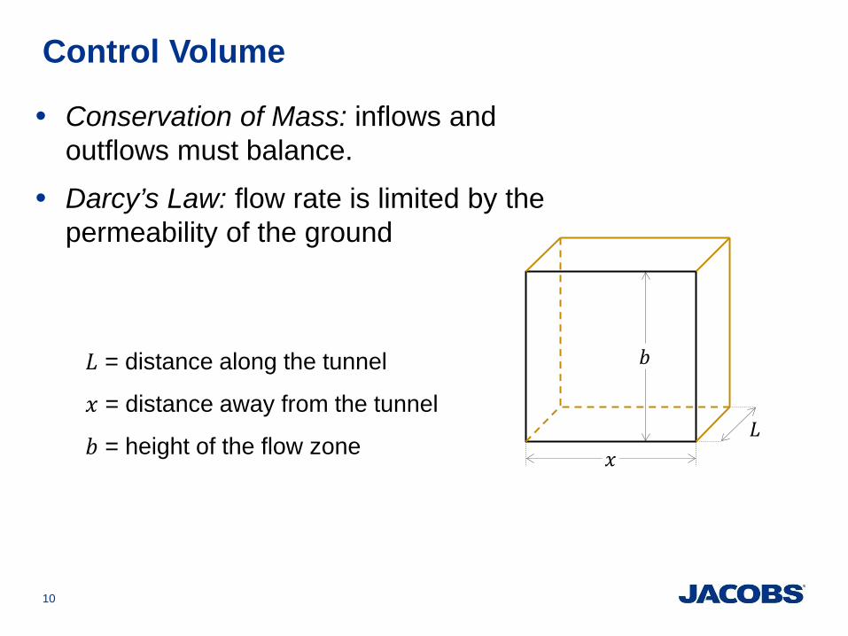
Control Volume
10
𝑏𝑏
𝐿𝐿 𝑥𝑥
• Conservation of Mass: inflows and outflows must balance.
• Darcy’s Law: flow rate is limited by the permeability of the ground
𝐿𝐿 = distance along the tunnel
𝑥𝑥 = distance away from the tunnel
𝑏𝑏 = height of the flow zone

Darcy’s Law
11
• 𝑄𝑄 is the flow rate
• ∆ℎ is the head difference over the distance 𝑥𝑥
• 𝐾𝐾 is the average permeability over the control volume
• 𝐾𝐾𝑏𝑏 is the transmissivity
𝑄𝑄𝑜𝑜𝑜𝑜𝑜𝑜 𝑄𝑄𝑖𝑖𝑖𝑖 𝑏𝑏
𝐿𝐿 𝑥𝑥
∆ℎ 𝑄𝑄 = 𝐾𝐾𝑏𝑏𝐿𝐿 ∆ℎ𝑥𝑥
Direction of flow
K is an average value over the whole control volume.

Conservation of Mass
12
• Flow going out must balance the sum of the flows coming in plus the change in storage
𝑄𝑄𝑜𝑜𝑜𝑜𝑜𝑜 = 𝑄𝑄1 + 𝑄𝑄2 + ⋯+∆𝑉𝑉𝑡𝑡
𝑄𝑄𝑜𝑜𝑜𝑜𝑜𝑜 𝑄𝑄1
𝑄𝑄2
∆𝑉𝑉
∆ℎ
• The change in storage is the change in volume over time ∆𝑉𝑉 𝑡𝑡⁄
• Water table decline is the most important way to change the storage.
Upstream Downstream
Recharge, Leakage

Formulas for Calculating Inflow
1. Based on Conservation of Mass and Darcy’s Law
2. Some assume a declining water table
3. Some assume steady-state conditions
4. The formula depends on the hydrogeology
13

Concept of Inflow to a Tunnel
14
• Tunnel is large relative to thickness of flow zone (𝑏𝑏). • Flow is lateral toward the tunnel, not radial around it. • Thickness (𝑏𝑏) of flow zone is important. • Tunnel width is not important
2𝑏𝑏
Actual Modeled
𝑏𝑏

Inflow Sketches
15
PROFILE
ℎ0 𝑏𝑏
ℎ0 Initial head (depth of tunnel below water table) 𝑏𝑏 Thickness of the flow zone prior to start of inflow
Tunnel
Unsaturated Ground
Static Water Table
Base of flow system
Saturated Ground
Flow is to one side of the tunnel only! Double the result to get flow to both sides

1: Declining Water Table
16
PROFILE
ℎ0 𝑏𝑏
𝑄𝑄 =𝐿𝐿𝜋𝜋𝑡𝑡
ℎ0 −ℎ02
2𝑏𝑏 𝑆𝑆𝐾𝐾𝑏𝑏
• Isotropic (non-stratified) flow system
• Water table draws down toward tunnel
• Water comes from existing storage
• Flow declines over time
• Flow can come from both sides (𝑄𝑄 × 2)
• Flow (𝑄𝑄) is proportional to 𝐾𝐾
𝑄𝑄 Inflow to one side of the tunnel 𝐿𝐿 Length of tunnel (or reach) 𝐾𝐾 Average horizontal permeablity 𝑆𝑆 Specific yield (free-draining porosity) 𝑡𝑡 Elapsed time since start of inflow
Adapted from Lohman, 1972

2: Upland Recharge
17
• Flow through random fractures or soil
• Water table draws down toward tunnel
• Recharge is captured over large area
• Recharge is independent of drawdown
• Flow can come from both sides (𝑄𝑄 × 2)
• Flow (𝑄𝑄) is proportional to 𝐾𝐾
PROFILE
ℎ0 𝑏𝑏
Precipitation
𝑄𝑄 Inflow to one side of the tunnel 𝐿𝐿 Length of tunnel (or reach) 𝐾𝐾 Average horizontal permeablity 𝑅𝑅 Average groundwater recharge rate
𝑄𝑄 = 𝐿𝐿 2𝐾𝐾𝑏𝑏𝑅𝑅 ℎ0 −ℎ02
2𝑏𝑏
Derived by Raymer from differential equations for continuity and Darcy’s Law

3: Downward Leakage in Stratified Ground
18
• Horizontally stratified flow system
• Lateral flow through permeable layer
• Steady water source above tunnel
• Rate of leakage depends on drawdown in main flow zone
• Flow can come from both sides (𝑄𝑄 × 2)
• Flow (𝑄𝑄) is proportional to 𝐾𝐾
Water
Leaky Layer ℎ0 𝑏𝑏𝑏
𝑏𝑏
𝑄𝑄 = 𝐿𝐿 ℎ0𝐾𝐾𝑏𝑏𝐾𝐾𝑏𝑏𝑏𝑏
𝑄𝑄 Inflow to one side of the tunnel 𝐿𝐿 Length of tunnel (or reach) 𝐾𝐾 Average horizontal permeablity of flow zone 𝐾𝐾𝑏 Vertical permeability of leaky layer
PROFILE
Lateral Flow
Derived by Raymer from differential equations for continuity and Darcy’s Law
𝑥𝑥
ℎ0 𝑏𝑏 Water Body
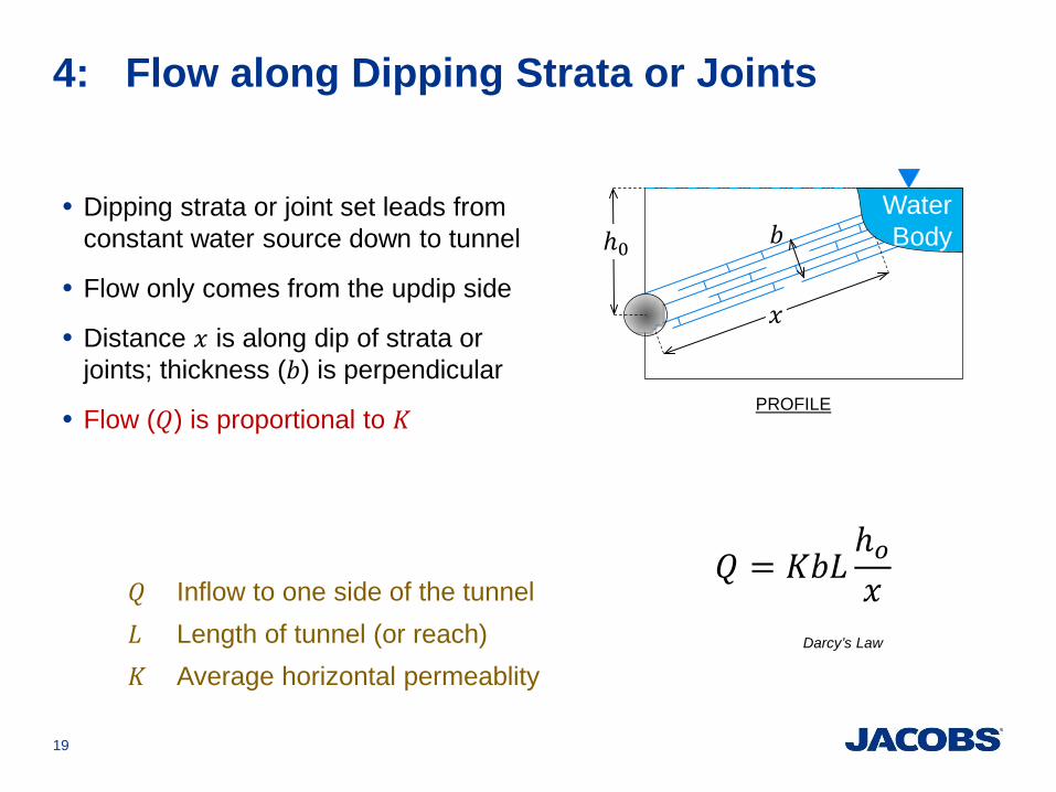
4: Flow along Dipping Strata or Joints
19
• Dipping strata or joint set leads from constant water source down to tunnel
• Flow only comes from the updip side
• Distance 𝑥𝑥 is along dip of strata or joints; thickness (𝑏𝑏) is perpendicular
• Flow (𝑄𝑄) is proportional to 𝐾𝐾 PROFILE
𝑄𝑄 Inflow to one side of the tunnel 𝐿𝐿 Length of tunnel (or reach) 𝐾𝐾 Average horizontal permeablity
𝑄𝑄 = 𝐾𝐾𝑏𝑏𝐿𝐿ℎ𝑜𝑜𝑥𝑥
Darcy’s Law

Numerical Modeling
1. Does the same thing as these equations, but with more detail
2. Highly advanced; requires much expertise
3. No better than the your understanding of the ground or the data you collect.
20
The geologic and permeability models are still the hard parts!

Problem of Permeability
1. Range of test results is enormous • six orders of magnitude: typically 10-7 to 10-1 cm/sec • 100,000 times greater than the other parameters
2. Formulas require the average for the rock mass
3. Problem of Scale Scale of the flow system
Scale of the tunnel Scale of the tests
21

Packer Tests
22
• Seal off an section of borehole • Inject water, record flow rate 𝑄𝑄
and applied pressure ∆𝑝𝑝 𝐾𝐾 =
𝑄𝑄∆𝑝𝑝
ln 𝐿𝐿 𝑟𝑟�2𝜋𝜋𝐿𝐿
𝐿𝐿 = length of interval 𝑟𝑟 = radius of borehole

Packer Tests – Scale
23
• Length – distance between the packers
• Time (Radius of Influence) – porosity and permeability – borehole and pipe volume
Recommendations: Standard length of about 20 ft (6 m) Standard duration of about 10 minutes

Scale Effects
The estimated average can change greatly depending on the number and scale of the tests.
1. Estimated average permeability tends to increase as the number of tests increases
2. Estimated average permeability tends to increase as the test zones become shorter
3. Estimated average permeability tends to increase if tests are not run long enough
24

Testing High Permeability Zones
Transient solutions that require much expertise 1. High-rate packer tests
• Perform in existing core holes • 4 to 6 hours, including injection and recovery
2. Pumping tests • Requires specially designed well network • Typically 24 to 72 hours continuous duration
Value: • Permeability of highest yielding zones • Insight into which formula to use
25

Testing Rules for Standard Packer Tests
1. Perform hundreds of tests • many statistical problems are solved with quantity
2. Perform all tests identically
3. Longer vertical intervals produce better results • 20 ft or 6 m is a good length.
4. Don’t skip any intervals
5. Use more sophisticated methods if necessary • High-rate packer tests (for takes >10 to 30 gpm) • Pumping tests in the most extreme circumstances
26

Conclusions
1. Put a groundwater expert on your team • from the beginning to plan the right investigation • teach your expert about tunnels and fractured rock
2. Inflow formulas depend on the hydrogeology • one formula does not fit all situations • square-root of permeability usually controls inflow • require a lot of geological judgement
3. Permeability is a problem • average of the tests is not the average for the ground • saving graces: lots of tests and the square root
27

Three Requirements for Inflow
28
1. Source • what is the source of the water?
2. Potential Energy • how much energy is available to drive the flow?
3. Pathway • how much resistance will the rock mass create? • will the pathway be circuitous?

Source, Head, Pathway
29
Soil
Water Table
River
Fractured Rock
Head
Tunnel
Pathways

Five Hydrogeologic Conditions
1. Massive Rock 2. Blocky Rock 3. Horizontal Fractures 4. Dipping Fractures 5. Karstic Systems
30
Only the open, water-bearing fractures matter!

Massive Rock
• No Significant Pathways = Dry Tunnel
31
Soil
Water Table
River
Fractured Rock

Blocky Rock
• Multiple Open Fractures = flow in any direction
32
Water Table
River
Tunnel
Soil
Fractured Rock

Horizontal Fractures
• Poor Vertical Connection to the Source
33
Soil
Water Table
River
Fractured Rock

Dipping Rock
• Direct Connection between Source and Tunnel
34
Soil
Water Table
River
Fractured Rock

Karstic Rock
• Pipelines to the Source
35
Soil
Water Table
River
Fractured Rock

Relevant Publications Jack Raymer, P.G., P.E. (Georgia and others)
[email protected] ; [email protected]
Raymer, J., and Maerz, N. H., 2014, “Effect of Variability on Average Rock-Mass Permeability,” Procedings of the the 48th Meeting of the American Rock Mechanics Association, ARMA 14-149, (2nd edition available by email from the author includes post-publication corrections.)
Raymer, J., 2010, “Geotechnical Variability and Uncertainty in Long Tunnels,” in North American Tunneling 2010, in Eckert and others, [eds.], Society of Mining Metallurgy and Exploration, Inc., Englewood, Colorado, pp. 316-322.
Raymer, J., 2005, “Groundwater Inflow into Hard Rock Tunnels: a New Look at Inflow Equations,” in Proceedings of the Rapid Excavation and Tunneling Conference, Society of Mining Metallurgy and Exploration, Inc., Englewood, Colorado (2nd edition available by email from the author includes post-publication corrections.
36

www.jacobs.com | worldwide 26 September 2016 Jacobs © Copyright


