22
Page 1 of 22 Groundwater Monitoring Plan Date: March 2016

Page 1 of 22
Groundwater Monitoring Plan
Date: March 2016
HSSE-PLN-SITE-001 PNR Groundwater Monitoring Plan
2 | P a g e
Preston New Road Groundwater Monitoring Plan
Management
System:
HSSE File Name: HSE-PLN-SITE-001
Approver: HSSE Director Version No: Issue 3.0
Reviewer:
Environmental Compliance
Advisor, Hydrogeological
Consultant
Date of
Issue: March 2016
Author: Environmental Engineer
Version Section Revision Information Date Reviser
0.1 All Draft text June 2015 Environmental Engineer
0.2 All Draft text HSSE Director Review and
Reviewers June 2015
Environmental Engineer
1.0 All
Submission to Environment Agency June 2015 Environmental Engineer
1.1 All Updated text and diagram 4, new text
page 3. September 2015
Environmental Engineer
1.2 All
Updated text and to CMT September 2015
Environmental Engineer
2.0 All
Finalised text September 2015
Environmental Engineer
3.0 All
Published text March 2015
HSE Manager

HSSE-PLN-SITE-001 PNR Groundwater Monitoring Plan
3 | P a g e
1.0 Purpose
The Groundwater Monitoring Plan (GWMP) details the necessary requirements to enable Environment Agency approval for pre-operational measure PO4 in table S1.3 Permit EPR/AB3101MW. The document will be submitted to the Environment Agency and remain live for the duration of the exploration project and as a permit holder.
2.0 Scope
The GWMP includes the following sections:
1. Monitoring objectives;
2. Groundwater conceptual model & risk assessment;
3. Borehole location;
4. Borehole design and construction method;
5. Monitoring parameters and frequency: and
6. Reporting
3.0 Monitoring Objectives
As part of the permitting and planning application Cuadrilla committed to monitor groundwater throughout the lifecycle of the operation. The subsequent permitting conditions requires the approval of a GWMP before drilling starts. The following objectives list what the GWMP will achieve during the lifecycle of the operation:
1) Provide baseline of natural groundwater conditions prior to operations beginning; 2) Support the findings of the hydrogeological risk assessment and conceptual model; 3) Compliance with environmental permit conditions, planning conditions and Infrastructure
Act 2015; 4) Triangulate directional flow of groundwater; 5) Monitor groundwater quality and dissolved gases before, during and after operations
combining continuous and variable spot sampling; 6) Where possible screening and analysing key determinands at site supported with laboratory
analysis; and 7) Documenting and reporting results.
To support Cuadrilla, an independent contractor will sample groundwater routinely. The independent contractor will be a member of a professional body with relevant competency and experience to carry out the sampling in accordance with best practice and ISO/ British Standards. Analysis will be carried out by independent UKAS/MCERTS accredited laboratories.

HSSE-PLN-SITE-001 PNR Groundwater Monitoring Plan
4 | P a g e
4.0 Conceptual Model & Risk Assessment
The conceptual model, (Preston New Road Environmental Statement, Arup 2014) assesses potential sources, pathways and receptors identifying credible migration pathways of containments to groundwater and surface water receptors. The conclusion from the Environment Statement for the potential impact on groundwater from site activities was low (not significant). Further assessment of gases flowing from below the Manchester Marl due to hydraulic fracturing of migrating to groundwater is assessed as not plausible. Table 1 provides an extract of the risk assessment within Chapter 11 of the Environmental Statement.

HSSE-PLN-SITE-001 PNR Groundwater Monitoring Plan
5 | P a g e
Table 1: Hydrogeology and ground gas assessment summary (Preston New Road Environment Statement, Arup 2014)
Source Pathway Receptor Probability Consequence Risk magnitude or
significance
Additional
mitigation
Residual effect/
risk magnitude
Offsetting and
enhancement
Project activity - Construction of well pad and access
Sediment in rainfall runoff during earthworks
→ Overland flow →
Watercourses (Carr Bridge
Brook and tributary), ponds and
any supported ecology
Low Low Low.
Not significant.
None in
addition to
embedded
mitigation – See
section 5.0
Low.
Not significant.
Not applicable
(N/A)
Diesel or lubricants spilled from vehicles and plant during construction of pad or access
→ Seepage into the ground or
overland flow
→ Middle Sands groundwater Low Low Low.
Not significant. As above
Low.
Not significant. N/A
→ Crops and livestock Low Low Low.
Not significant. As above
Low.
Not significant. N/A
→
Watercourses (Carr Bridge
Brook and tributary), ponds and
any supported ecology
Low Low Low.
Not significant. As above
Low.
Not significant. N/A
→
Off-site human health (contact
with contaminated surface water
or soil)
Low Low Low.
Not significant. As above
Low.
Not significant. N/A
Project activity - Drilling
Pad and surface activities (during drilling)
Spillage of fluids on the
well pad due to failure of
equipment or
infrastructure, vehicle
collision, or site operative
error
→
Vertical downwards migration
through a defect in the
membrane or well cellar
→ Middle Sands groundwater Low Low Low.
Not significant. As above
Low.
Not significant. N/A
→
Collection in site drainage
system and overflow onto
adjacent ground and infiltration
→
Middle Sands groundwater Low Low Low.
Not significant. As above
Low.
Not significant. N/A
Crops and livestock Low Low Low.
Not significant. As above
Low.
Not significant. N/A
→
Collection in site drainage
system and overflow into
watercourse
→
Watercourses (Carr Bridge
Brook and tributary) and any
supported ecology
Low Low Low.
Not significant. As above
Low.
Not significant. N/A
→ Off-site human health (contact
with contaminated water) Low Low
Low.
Not significant. As above
Low.
Not significant. N/A
Fire fighting foam or water
→
Vertical downwards migration
through a defect in the
membrane or well cellar
→ Middle Sands groundwater Low Low Low.
Not significant. As above
Low.
Not significant. N/A
→
Collection in site drainage
system and overflow onto
adjacent ground and infiltration
→
Middle Sands groundwater Low Low Low.
Not significant. As above
Low.
Not significant. N/A
Crops and livestock Low Low Low.
Not significant. As above
Low.
Not significant. N/A
→
Collection in site drainage
system and overflow into
watercourse
→
Watercourses (Carr Bridge
Brook and tributary) and any
supported ecology
Low Low Low.
Not significant. As above
Low.
Not significant. N/A
→ Off-site human health (contact
with contaminated water) Low Low
Low.
Not significant. As above
Low.
Not significant. N/A
Failure of equipment
causes release of fluid at
high pressure
→ Liquid spray off site through the
Site boundary fence → Crops and livestock Low Low
Low.
Not significant. As above
Low.
Not significant. N/A

HSSE-PLN-SITE-001 PNR Groundwater Monitoring Plan
6 | P a g e
Source Pathway Receptor Probability Consequence Risk magnitude or
significance
Additional
mitigation
Residual effect/
risk magnitude
Offsetting and
enhancement
→ Off-site human health (a person
standing outside the Site
boundary fence)
Low Low Low.
Not significant. As above
Low.
Not significant. N/A
Off site road traffic
accident resulting in spill
of potentially
contaminating materials
→ Spill of contents of vehicle in
transit onto public highway
→ Off-site human health (exposure
to spilled material) Low Low
Low.
Not significant. As above
Low.
Not significant. N/A
→ Water environment along transit
route Low Low
Low.
Not significant. As above
Low.
Not significant. N/A
Well construction and integrity (during drilling)
Drilling fluids
Naturally poor quality
groundwater
→
Loss of well integrity due to
poor well construction resulting
in release from the well
→ Sherwood Sandstone
groundwater Very Low Low
Low.
Not significant. As above
Low.
Not significant. N/A
→ Middle Sands groundwater Very Low Low Low.
Not significant. As above
Low.
Not significant. N/A
→
Loss of well integrity due to
natural seismicity resulting in
release from the well
→ Sherwood Sandstone
groundwater Very Low Low
Low.
Not significant. As above
Low.
Not significant. N/A
→ Middle Sands groundwater Very Low Low Low.
Not significant. As above
Low.
Not significant. N/A
Hazardous ground gases
from below the
Manchester Marls
→
Loss of well integrity resulting
in gas migration to shallow
groundwater and abstraction of
groundwater for use within a
confined space
→ Off-site human health (users of
groundwater abstractions) No plausible linkage
→
Loss of well integrity resulting
in gas migration to shallow soils
followed by entry into buildings
(or other confined spaces) on or
off site.
→ On-site human health (site
workers and visitors No plausible linkage
→ Off-site human health (users of
off-site confined spaces) No plausible linkage
Project activity - Hydraulic fracturing
Pad and surface activities (see ‘Pad and surface risks during drilling’ identified above)
Well integrity (during fracturing)
Hydraulic fracturing fluid
Flowback fluid
Naturally poor quality
groundwater (from below
the Manchester Marls)
→
Loss of well integrity due to
poor well construction resulting
in release from the well
→ Sherwood Sandstone
groundwater Very Low Low
Low.
Not significant. As above
Low.
Not significant. N/A
→ Middle Sands groundwater Very Low Low Low.
Not significant. As above
Low.
Not significant. N/A
→
Loss of well integrity caused by
hydraulic fracturing resulting in
release from the well
→ Sherwood Sandstone
groundwater Low Low
Low.
Not significant. As above
Low.
Not significant. N/A
→ Middle Sands groundwater Low Low Low.
Not significant. As above
Low.
Not significant. N/A
→
Loss of well integrity due to
induced seismicity resulting in
release from the well
→ Sherwood Sandstone
groundwater Very Low Low
Low.
Not significant. As above
Low.
Not significant. N/A
→ Middle Sands groundwater Very Low Low Low.
Not significant. As above
Low.
Not significant. N/A
Hazardous ground gases
from below the
Manchester Marls and
dissolved in flowback
fluidwell pad
→
Loss of well integrity resulting
in gas migration to shallow
groundwater and abstraction of
groundwater for use within a
confined space
→ Off-site human health (users of
groundwater abstractions) No plausible linkage

HSSE-PLN-SITE-001 PNR Groundwater Monitoring Plan
7 | P a g e
Source Pathway Receptor Probability Consequence Risk magnitude or
significance
Additional
mitigation
Residual effect/
risk magnitude
Offsetting and
enhancement
→
Loss of well integrity resulting
in gas migration to shallow soils
followed by vertical migration
into buildings (or other confined
spaces) on or off site.
→
On-site human health (site
workers and visitors No plausible linkage
Off-site human health (users of
off-site confined spaces) No plausible linkage
Induced fractures
Hydraulic fracture fluid
Naturally poor quality
groundwater (from the
Bowland Shale)
→
Fractures propagating beyond
the target zone which then
connect to preferential
flowpaths (natural
discontinuities or deep
boreholes)
→ Sherwood Sandstone
groundwater Very Low Low
Low.
Not significant. As above
Low.
Not significant. N/A
→ Middle Sands groundwater Very Low Low Low.
Not significant. As above
Low.
Not significant. N/A
Hazardous ground gases
(from below the Bowland
Shale)
→
Gas migration along induced
fractures, natural fissures and
faults to shallow groundwater
and abstraction of groundwater
for use within a confined space.
→ Off-site human health (users of
groundwater abstractions) No plausible linkage
→
Gas migration along induced
fractures, natural fissures and
faults to shallow soils and above
ground confined spaces on-site
or off-site
→ On-site human health (site
workers and visitors) No plausible linkage
→ Off-site human health (users of
off-site confined spaces) No plausible linkage
Residual fracturing fluid in
Bowland Shale →
Groundwater flow, including
diffusion, through bedrock
→ Sherwood Sandstone
groundwater No plausible linkage
→ Middle Sands groundwater
Project activity - Initial and extended flow testing
There are no additional S-P-R linkages in the initial and extended flow testing stage to those identified above.
Project activity - Decommissioning and restoration
(Only additional S-P-R linkages to those identified above presented below)
Hydraulic fracturing fluid
Naturally poor quality
groundwater (from below
the Manchester Marls)
→
Loss of well integrity due to
poor well construction resulting
in release from the well
→ Sherwood Sandstone
groundwater Very Low Low
Low.
Not significant. As above
Low.
Not significant. N/A
→ Middle Sands groundwater Very Low Low Low.
Not significant. As above
Low.
Not significant. N/A
→
Loss of well integrity due to
natural seismicity resulting in
release from the well
→ Sherwood Sandstone
groundwater Very Low Low
Low.
Not significant. As above
Low.
Not significant. N/A
→ Middle Sands groundwater Very Low Low Low.
Not significant. As above
Low.
Not significant. N/A
→ Loss of well integrity due to long term well degradation
→ Sherwood Sandstone
groundwater Very Low Low
Low.
Not significant. As above
Low.
Not significant. N/A
→ Middle Sands groundwater Very Low Low Low.
Not significant. As above
Low.
Not significant. N/A
Ground gas (from below
the Manchester Marls) →
Loss of well integrity due to long term well degradation resulting in: migration to shallow groundwater and
→ Off-site human health (users of
groundwater abstractions) No plausible linkage

HSSE-PLN-SITE-001 PNR Groundwater Monitoring Plan
8 | P a g e
Source Pathway Receptor Probability Consequence Risk magnitude or
significance
Additional
mitigation
Residual effect/
risk magnitude
Offsetting and
enhancement
abstraction of groundwater for use within a confined space; or migration into buildings or other confined spaces.
→ Off-site human health (users of
off-site other enclosed spaces) No plausible linkage

HSSE-PLN-SITE-001 PNR Groundwater Monitoring Plan
9 | P a g e
5.0 Embedded Mitigation
Pressure testing, formation integrity testing (FIT), and/ or wireline logging (such as cement bond logs “CBL”) will be used to confirm cementation integrity, or identify anomalies from drilling muds if present, to verify that the integrity of the well system. A report will be submitted to the Environment Agency consistent with pre operational measure PO5 and PO6.
Throughout the life of the well, the three annuli A, B and C are monitored using a digital gauge or equivalent method to download readings on annuli pressure. The frequency of monitoring will be dictated by the data being downloaded ranging from potentially daily to quarterly downloads.
6.0 Borehole Location
Borehole locations will be located as per indicative drawing 1 along the site perimeter fence line consistent with the planning application, LCC/2014/0097. There is provision to increase the number of boreholes at the site if requested by the Environment Agency. The 3 dual sampling boreholes will triangulate the groundwater flow by measuring the hydraulic gradient from the three dual wells.
Drawing 1: Preston New Road Borehole Locations
HSSE-PLN-SITE-001 PNR Groundwater Monitoring Plan
10 | P a g e
7.0 Borehole Design & Construction Method
The design of the proposed 3 monitoring boreholes is in accordance with relevant guidance and standards including Environment Agency Guidance (Environment Agency, 2006), BSI standards (BS 8576: 2013) and relevant publications; Clarke L, 1988. In addition, previous knowledge gained by installing groundwater monitoring boreholes at other operational sites, such as Preese Hall, Anna’s Road, Becconsall and Grange Hill have contributed to the design of the borehole.
There are two different designs being proposed, the first is a nested borehole and a second option is to utilise the discrete zone CMT multilevel system.
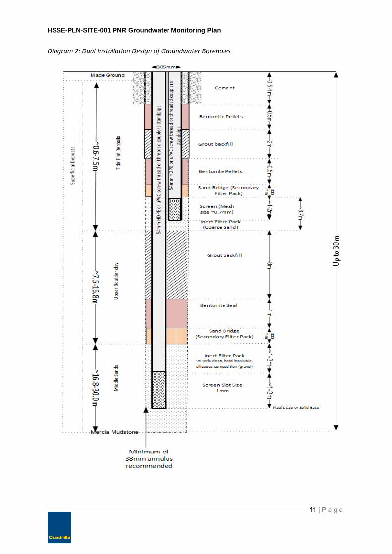
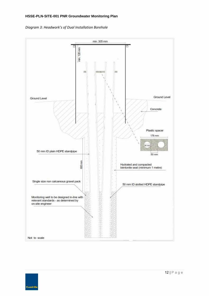
Both groundwater monitoring borehole options will target two discrete horizons; shallow Glacial Till (Upper Bolder Clay) ~0.6m to 7.5m below ground level and deeper Middle Sands estimate to be approximately ~16m to 30m below ground level). The nested borehole installation in a single borehole is illustrated in Diagram 2, 3 and 4. The CMT option is illustrated in Diagram 5 and 6. The depths and locations are based on the site conceptual model from Diagram 1 and the site condition report (HSE-Permit-INS-PNR-003) which provides a geological context for the site. Due to the expected high water table experienced from previous sites the GasClam®, in order to operate correctly, will be installed above the surface in a specialist designed steel casing headwork’s as illustrated in Diagram 3, 4 (nested option) and 6 (CMT option).
7.1 Nested Borehole
Each borehole will operate a GasClam® to continually monitoring methane and carbon dioxide levels, as well as providing groundwater temperature, atmospheric and borehole pressure and a groundwater level logger. A standard diameter of ~50mm uPVC or HDPE standpipe has been selected to account for the GasClam® installation as well as being able to access groundwater to undertake dissolved ground gas sampling and groundwater quality monitoring.
Selection of materials is based on the monitoring objectives and longevity of the borehole installation. Either a uPVC or HDPE standpipe is the preferred option accounting for the monitoring parameters of hydrocarbons, metals and salts. Selection of other materials including bentonite pellets and sand bridges have been made in accordance with guidance and standards.
Material selection within response zone is designed to ensure the material does not react with the groundwater and provides an inert environment. Details of the filter pack are shown in the design drawing “greater than 95 per cent silica or preferably 99 per cent silica”. Based on the particle size of the Middle Sands; range of 187μm to 500μm, a screen slot size of 1mm has been designed and 0.7mm for the Glacial Till to prevent 90% of the filter pack material entering the monitoring borehole. Lubricants used during drilling of the monitoring wells wherever possible be inert or non-contaminative, such as vegetable oil, to reduce the possible effects on the groundwater quality.
HSSE-PLN-SITE-001 PNR Groundwater Monitoring Plan
11 | P a g e
Diagram 2: Dual Installation Design of Groundwater Boreholes
HSSE-PLN-SITE-001 PNR Groundwater Monitoring Plan
12 | P a g e
Diagram 3: Headwork’s of Dual Installation Borehole

HSSE-PLN-SITE-001 PNR Groundwater Monitoring Plan
13 | P a g e
Diagram 4: Example of a GasClam within the Headwork’s*
*This drawing is representative of how the GasClam is installed within a 50mm standpipe. This would simply be
duplicated in the dual installation borehole as per diagram 3.

HSSE-PLN-SITE-001 PNR Groundwater Monitoring Plan
14 | P a g e
The gravel filter pack will cover the top of the screen slots between 1000 and 1500mm to allow for settlement, however the design drawing indicates a wider area to accommodate potential variation during construction of the borehole.
7.2 CMT Multilevel
The Solinst CMT Multilevel discrete well system provides the best available approach to monitoring multiple discrete zones within the target groundwater zone formation without the need to drill multiple boreholes. Photo 1 provides an illustration from RS Hydro website of how the multilevel system splits into intervals targeting discrete zones. A hyperlink to the pdf installation manual accompanies this plan within Appendix A. Each borehole, similar to the nested borehole will have a GasClam® installed within the headworks to continually monitoring methane and carbon dioxide levels, as well as providing temperature, atmospheric and borehole pressure. A groundwater level logger shall also be installed at the site. The materials selection and construction installation of the CMT system is the same as the nested borehole apart from replacing the 50mm HDPE standpipe with the CMT multilevel system. The multi-level system main advantage in comparison to the nested borehole is that it can target several depths of the groundwater bearing unit, providing a larger source of data e.g. stratification of water quality. The headworks has been designed to accommodate the installation of the GasClam® and the CMT system. To gain access to the surface of the CMT system the steal headworks and a 50mm standpipe accommodating the GasClam® will split into two parts once the GasClam® has been removed. The sequencing of monitoring will follow a set process;
1. Monitor the headspace first; 2. Data download from the GasClam®; and 3. Groundwater quality parameters
Diagram 6 provides a drawing of the arrangements for accessing the CMT pipe.
7.3 GasClam® Monitoring using CMT
The ability to monitor multiple discrete zones with a single GasClam® at the surface will not be able to identify the source of gas. The intention of the GasClam is to screen for changes in ground gases on a continually basis. In the unlikely event a significant variation in the baseline data is identified each discrete zone will be sampled for dissolved ground gases for offsite laboratory analysis. This shall be conducted in accordance with section 8.4. The sampling will indicate the origin of the dissolved ground gas.

HSSE-PLN-SITE-001 PNR Groundwater Monitoring Plan
15 | P a g e
Diagram 5 CMT Multilevel System targeting 5 discrete zones.

HSSE-PLN-SITE-001 PNR Groundwater Monitoring Plan
16 | P a g e
Diagram 6 CMT Multilevel Headworks

HSSE-PLN-SITE-001 PNR Groundwater Monitoring Plan
17 | P a g e
7.4 Construction Method
The construction method for either proposed borehole options is a cable percussive method. The rig is equipped with a winch, which is driven by a diesel engine, and a tripod derrick of about 7m height. The derrick folds down so that the rig can be towed by a four-wheel drive vehicle. Cable percussive rigs are equipped with in-situ sampling equipment to establish and log the boreholes. The soil and arising extracted from the borehole will be sampled at the surface. The Preese Hall groundwater monitoring wells utilised cable percussive technique. The option has been chosen as the preferred choice in accordance with BS 5667-22-2010 through very soft to firm to fine soils. The construction method will avoid, where possible, the use of drilling fluids to prevent cross contamination of the unsaturated zone. If drilling fluid is to be used then Cuadrilla will notify the Environment Agency before use. Once a drilling contractor is selected Cuadrilla will notify the Environment Agency, including a date of when the drilling will commence. The drilling technique will also be documented within the groundwater borehole installation report as required by pre-operational measure PO7.
The drilling contractor shall provide the necessary spill kits for the operation, store chemicals and liquids in accordance with Pollution Prevention Guidance (PPG 1 and PPG6) and manage waste in accordance with the planning condition and waste regulations. The mixing of bentonite/grout or cement will also be managed on an impermeable membrane. The drilling contractor shall submit a method statement to Cuadrilla for approval before operations start detailing how they will comply with planning conditions and general industry best practice.
The construction of the boreholes strata encountered will be recorded in accordance with the relevant BS EN ISO 14688-1, BS EN ISO 14688-2 and BS EN ISO 14689-1. The descriptions of the strata encountered will include reference to the presence of any biodegradable material or other material that might give rise to gas, including the proportion of such material when this is practicable. If the method of installation does not allow the strata to be recorded, the ground conditions around the response zone should be inferred from other nearby investigation points, such as other boreholes from Anna’s Road. Each well will be logged and recorded to demonstrate that the site conceptual model is consistent with the boreholes. The records will form part of the report in accordance with pre-operational measure PO7.
The position of each of the boreholes will be surveyed to National Grid and the ground level will be determined to Ordnance Survey Datum to allow the groundwater elevation to be calculated and hence groundwater flow gradient to be estimated.
8.0 Monitoring Parameters
A combination of ground gas and groundwater quality will be monitored at each borehole. Surface watercourses will also be monitored at the same time as groundwater throughout the lifecycle of the operation. Please review Preston New Road Waste Management Plan for further details regarding surface water sampling. Monitoring will occur prior to construction (baseline monitoring) in accordance with pre-operational measure PO8, during the well pad construction and well drilling, fracturing and flow testing, and decommissioning (well abandonment and site restoration) stages.
Sampling of the unsaturated zone will be conducted during borehole installation. In upper sections e.g. superficial deposits, a cable percussion technique can be driven into the upper layers with hollow tools. The hollow tools retain the soils and rocks within an inner cylinder and return the rock/soils to the surface. The soils will be logged in accordance with BS 5930: 1999 and sent off site for chemical analysis.
8.1 GasClam
Cuadrilla’s monitoring contractor will install both a GasClam® and a water quality down-hole probe into the monitoring well. The purpose of the GasClam® is to monitor methane, carbon dioxide and

HSSE-PLN-SITE-001 PNR Groundwater Monitoring Plan
18 | P a g e
oxygen concentrations within the Middle Sands and Glacial Till. In addition to the gases other parameters will be monitored: groundwater level, pressure and temperature. The GasClam® will be set to record at intervals (range 1minute to 1 hour) and subject to monthly maintenance visits to change moisture filter, batteries and conduct bump tests (site calibration). Records of the GasClam® maintenance will be documented per visit and downloaded data reported as part of the quarterly permit reporting requirements.
8.2 Ground Gas Sampling
The presence of methane alone does not provide evidence of its source. It is therefore necessary to carry out a suitable level of gas-sampling and laboratory analysis to fully characterise the provenance of any methane or associated gases identified.
The following gas sampling and testing approaches shall be adopted to provide a baseline dataset. Additional testing may be required dependent on findings.
8.3 Headspace Sampling
Gas samples will be taken from each borehole and scheduled for laboratory analysis for presence and concentration of selected bulk gases and trace compounds. Sampling of boreholes headspace will confirm the accuracy of the GasClam® and also eliminate potential stratification of gas within the borehole. This will be achieved by circulating the gas around the headspace before sampling.
Gas sampling methods will typically comprise the use of Tedlar bags and/or Gresham tubes. Samples of the headspace will be taken on a quarterly basis or more frequently if there is significant difference in accuracy of the GasClam® detection.
Where sufficient concentrations of methane and/or carbon dioxide are detected, these will be scheduled for C12/C13 isotopic analysis to provide evidence of the gases’ age and provenance.
8.4 Dissolved Gas & Groundwater Quality Sampling
Further groundwater sampling will be undertaken to monitor the quality of groundwater and dissolved ground gas monitoring as per pre-operational measure (PO8). Water sampling of the boreholes will use a bladder pump system or equivalent (peristaltic pump, micro double valve pump,) depending on the design in order to reduce the chance of ‘de-gassing’ of the water sample. As a minimum six sample rounds (1 round of sampling will equal 6 samples: 3 site dual boreholes x 2 nested boreholes) or six sample rounds from the discrete locations (x3 boreholes, x6 discrete zones) will be taken before drilling to establish a baseline and further sampling will continue at frequencies outlined in Table 3 Column 3.
As part of the water quality monitoring a number of parameters will be collected at site during purging. The parameters; pH, electrical conductivity, temperature and dissolved oxygen are collected for 3- 5minute intervals until stablished. The stabilisation of these measures will indicate when a groundwater sample can be taken. The quantity of purging of the borehole shall follow the requirements established in BS ISO 5667-18:2001 e.g. 3 times the borehole volume but subject to the site requirements.
The targets used to determine stabilisation are presented in Table 2 and are based on the US EPA methodology (Puls, 1996).

HSSE-PLN-SITE-001 PNR Groundwater Monitoring Plan
19 | P a g e
Table 2: In situ groundwater stabilisation criteria
Parameter Stabilisation Target
Dissolved Oxygen +/- 10%
Eh +/- 10mV
pH +/- 0.1 [pH units]
Electrical Conductivity +/- 3%
Each sampling technique shall be taken in accordance with BS ISO 5667-11:2009 with records of the site sample and chain of custody for the transfer of the sample being documented.
8.5 Monitoring Frequency
The proposed monitoring frequency is designed to provide a robust assessment of continuous and judgemental sampling based on the risk assessment.
The utilisation of the GasClam® continuous monitoring provides a screen complimenting laboratory analysis for dissolved gases and groundwater quality as described in section 7.0.
Table 3 outlines the frequency of monitoring for the different phases of operations.

HSSE-PLN-SITE-001 PNR Groundwater Monitoring Plan
20 | P a g e
Table 3: Preston New Road Groundwater Monitoring Frequency
Phase GasClam Judgemental Dissolved Gas and Water Quality
Justification
Baseline Continuous Monthly* Site condition report HSE-Permit-INS-PNR-003) did not identify potential sources of contaminants which could impact groundwater e.g. landfill. The site is based on an agricultural setting. Limited activity from site operations.
Site Construction
Continuous Monthly Continuation of monthly monitoring during site construction. No drilling into the groundwater bearing zones will take place.
Drilling Continuous Weekly Weekly during drilling and then extending to monthly once the upper sections of Sherwood sandstone is cased off.
Hydraulic Fracturing
Continuous Weekly Well is cased off, stimulation of hydrocarbon bearing zone at depth. Increased monitoring as a precautionary approach.
Initial Well Testing
Continuous Monthly Well is cased off, continue surveillance monitoring of the groundwater based on the risk assessment
Extended Well Testing
Continuous Monthly Well is cased off, continue surveillance monitoring of the groundwater based on the risk assessment
Plug and Abandonment
Continuous Monthly Well is plugged and abandoned with no migration pathway.
Post Abandonment
Continuous Monthly - Quarterly** Subject to change once the site history has been reviewed.
*Depending on the consistency with the site conceptual model a total of 3 monthly baseline samples are to be taken prior to the commencement of drilling of the injection wells (Pre-operational condition 8).
** This monitoring frequency is provisional and will be subject to the prevailing regulatory conditions at the time. The duration and frequency of the Post Abandonment monitoring will be agreed with the regulator prior to abandonment, based on the findings of the preceding monitoring programme.
The total duration of sampling before hydraulic fracturing is subject to the requirements outlined within the Infrastructure Act 2015 and future secondary legislation. Once secondary legislation has been established and transposed into legislation, Cuadrilla will comply with the requirements.

HSSE-PLN-SITE-001 PNR Groundwater Monitoring Plan
21 | P a g e
9.0 Reporting
Once the groundwater boreholes have been constructed a report will be submitted to the Environment Agency to meet the requirements of pre-operational measure PO7 detailing the installation of each borehole.
Reporting will continue throughout the lifecycle of the operations to comply with the permit. The parameters outlined in pre-operational measure PO8 will remain consistent throughout the operations and reported to the Environment Agency on a quarterly basis unless agreed in writing with the Environment Agency.
In accordance with schedule 4 of EPR/AB310MW the reporting of groundwater data will be submitted to the Environment Agency on a quarterly basis in Groundwater 1 format unless agreed in writing with the Environment Agency.
10.0 References
Arup; Preston New Road Environment Statement, June 2014
BS ISO 5667-11:2009, Water quality. Sampling. Guidance on sampling of groundwater
BS ISO 5667-18:2001, Water quality. Sampling. Guidance on sampling of groundwater at contaminated sites
BS 5930:1999+A2:2010, Code of practice for site investigations
BS 8576:2013, Guidance on investigations for ground gas. Permanent gases and Volatile Organic Compounds (VOCs)
BS 10175:2011, Investigation of potentially contaminated sites – Code of practice (+A1:2013)
BS EN ISO 14688-1:2002+A1:2013 Geotechnical investigation and testing. Identification and classification of soil. Identification and description
BS EN ISO 14688-2:2004+A1:2013 Geotechnical investigation and testing. Identification and classification of soil. Principles for a classification
BS EN ISO 14689-1:2003 Geotechnical investigation and testing. Identification and classification of rock. Identification and description
Clarke, L; The Field guide to Water Wells and Boreholes, 1988
Environment Agency; Guidance on the design and installation of groundwater quality monitoring points, 2006
Ground Gas Solutions; Preese Hall Baseline Monitoring Report, June 2012
RS Hydro; http://www.rshydro.co.uk/PDFs/Solinst/403-7channel-Manual.pdf Accessed September 2015
Puls, R. W. and Barcelona, M. J., 1996, Ground Water Issue, Low-Flow (Minimal Drawdown) Groundwater Sampling Procedures, EPA/540/S-95/504
UK Onshore Shale Gas Well Guidelines; Exploration and Appraisal Phase, Issue 3, March 2015

HSSE-PLN-SITE-001 PNR Groundwater Monitoring Plan
22 | P a g e
Appendix A CMT Data Sheet
http://www.rshydro.co.uk/PDFs/Solinst/403-7channel-Manual.pdf


