Cylinder head and valvesDistortion of cylinder head bottom mm (in) Within 0.05 (0.002) 0.2 (0.008)Grinding limit of cylinder head bottom mm (in) − 0.2 (0.008)
Overall height of cylinder head mm (in) 128.5 (5.06) −
Overall length of valve mm (in) Intake 113.18 (4.456) 112.68 (4.436)Exhaust 105.89 (4.169) 105.39 (4.149)
Piston ring end gap mm (in) Number 1 0.15 − 0.25 (0.006 − 0.011) 0.8 (0.03)Number 2 0.25 − 0.40 (0.010 − 0.016) 0.8 (0.03)Oil 0.10 − 0.35 (0.004 − 0.014) 1.0 (0.04)
Clearance of connecting rod big end thrust mm (in) 0.10 − 0.25 (0.004 − 0.010) 0.4 (0.016)Difference of outside diameter of connecting rod bolt mm (in)
− 0.1 (0.04)
Connecting rod bearing oil clearance mm (in) 0.018 − 0.045 (0.0007 − 0.0018)
0.1 (0.04)
Crankshaft and cylinder blockUnderhead length of crankshaft bearing cap bolt mm (in)
75.5 − 76.5 (2.972 − 3.012) −
Crankshaft end play mm (in) 0.05 − 0.25 (0.002 − 0.010) 0.4 (0.016)Crankshaft journal oil clearance mm (in) 0.012 − 0.030 (0.0005 −
0.0012)0.08 (0.0031)
Distortion of cylinder block top surface mm (in) − 0.05 (0.0020)
Grinding limit of cylinder block top surface mm (in) − 0.2 (0.008)
Cylinder block cylinder bore mm (in) 88 (3.46) −
Cylindricity of cylinder block mm (in) 0.0076 (0.0003) −
Item Standard value Limit
Item Standard valueCylinder head and valveCylinder head oversize valve seat bore diameter mm (in) Intake 0.30 Over
size36.22 − 36.24 (1.426 − 1.427)
Exhaust 0.30 Over size
30.22 − 30.24 (1.190 − 1.191)
Cylinder head oversize valve guide bore diameter mm (in) 0.25 Over size
NEW TIGHTENING METHOD BY USING PLASTIC REGION TIGHTENING BOLT.
Plastic region tightening bolts are used in some parts of the engine. Install these bolts according to the method described in the relevant section because the tightening method of these bolts are different from the conventional method. The service limit is determined for these bolts. Be sure to strictly follow the service limit described in the body of the manual.• Parts to be used
1. Cylinder head bolt2. Bearing cap bolt3. Connecting rod cap bolt
• Tightening methodAfter tightening to the specified tightening torque, further tighten 90° and 90° , or 180° (90° + 90° ). Follow the tightening method described in the body of the manual because the tightening method differs from part to part.
Piston and connecting rodConnecting rod cap bolt 5.0 N⋅ m (44 in-lb) → 20 N⋅ m (15 ft-lb) →
+90°
Crankshaft and cylinder blockCrankshaft sensing ring bolt 11 ± 1 N⋅ m (98 ± 8 in-lb)Bearing cap bolt 26.5 ± 2.0 N⋅ m (20 ± 1 ft-lb) → +45°
Item Specification
TSB Revision
SEALANTSENGINE OVERHAUL <2.4L ENGINE> 11D-7
SEALANTSM1113000503122
NOTE: The number in square brackets shows the genuine part number..
FORM-IN-PLACE GASKET (FIPG)The engine has several parts to which the form-in-place gasket (FIPG) is used. To sufficiently achieve the aims of this gasket, it is necessary to pay attention to the application amount, procedure, and surface status.If the application amount is too small, a leakage will occur. If the application amount is excessive, the FIPG will overflow and cause a clogging or narrowing of water and oil paths. Therefore, to eliminate the leak from the joint, it is indispensable that the FIPG be applied with a correct amount and without any gap.Because the FIPG used for the engine parts becomes hardened by the reaction with the atmo-spheric moisture, it is normally used for the metal flange section..
CAUTIONReapply the FIPG with care to the followings.1. Completely remove the old FIPG including the
residue in gaps of parts.2. Using Mitsubishi genuine parts cleaner
(MZ100387) or equivalent, degrease the FIPG application surface carefully.
3. According to the FIPG application proce-dures, apply it accurately.
.
DISASSEMBLYThe parts installed with the FIPG can be disassem-bled easily without using any special method. How-ever, in some cases, it is necessary to tear the sealant in between the mating surfaces by tapping the parts with a wooden hammer or similar tools. It is acceptable to lightly hit in a smooth, thin gasket scraper into the mating surface, but, in this case, a sufficient caution is required not to damage the mat-ing surface. The oil pan FIPG cutter (Special tool: MD998727) is provided. Thus, use this special tool..
GASKET SURFACE CLEANINGUse a gasket scraper or wire brush to completely remove all the foreign materials adhering to the gas-ket surface. Check that the FIPG application surface is smooth. There must be no grease or foreign mate-rial adhesion to the gasket surface. Do not forget to remove the old FIPG remaining in the mounting hole and tapped hole..
APPLICATION PROCEDUREApply the FIPG with a specified diameter and without any gap. Completely enclose around the mounting hole. When the FIPG is not hardened, it can be wiped off. When the FIPG is still moistened, perform the installation to the specified position. At the time of installation, prevent the FIPG from adhering to loca-tions other than it is necessary. After the installation,
Points of application Specified sealant / adhesiveDrive plate bolt Three bond 1324 or equivalentFlywheel boltOil pan Three bond 1227D, Three bond 1217G (Mitsubishi Part
No.1000A923), Three bond 1207F (Mitsubishi Part No.1000A992), LOCTITE 5971, LOCTITE 5970, LOCTITE 5900 or equivalent
Ladder frame
Cylinder head cover (matching area of the cylinder head and the timing chain case assembly)
Three bond 1227D, Three bond 1217G(Mitsubishi Part No.1000A923) or equivalent
Three bond 1227D, Three bond 1217G(Mitsubishi Genuine Tool number and name 1000A923) or equivalent
Cylinder head gasket (matching area of the cylinder block and the cylinder head)
Three bond 1217G(Mitsubishi Part No.1000A923) or exact equivalent
Timing chain caseEngine coolant temperature sensor Three bond 1324N, LOCTITE 262 or equivalentEngine oil pressure switch Three bond 1212D, Three bond 1215 or equivalent
TSB Revision
SPECIAL TOOLSENGINE OVERHAUL <2.4L ENGINE>11D-8
until a sufficient period of time (approximately for t one hours) elapses, do not contact the oil or water to the application area. Also, do not start the engine. Because the FIPG application procedure may differ depending on the application area, apply the FIPG according to the procedure described in the text.
SPECIAL TOOLSM1113000603055
Tool Tool number and name
Supersession Application
MB991883Flywheel stopper
− Securing of drive plate or flywheel
MB991398Spark plug wrench
− Removal and installation of spark plug
MB992106O-ring installer
− Installation of O-ring on injector injection nozzle side
MB991396Oil filter wrench
− Removal and installation of oil filter
MD998727Oil pan FIPG cutter
MD998727-01 Removal of oil pan
MB991448Bushing remover and installer base
MB991448-01 Press fit of front oil seal
MB991883
B992106
B991396
D998727
TSB Revision
SPECIAL TOOLSENGINE OVERHAUL <2.4L ENGINE> 11D-9
MD998735Valve spring compressor
MD998735-01 Compression of valve spring
MB992089Retainer holder C
MB992089-01
MB992085Valve stem seal pliers
− Extraction of valve stem seal
MD998737Valve stem seal installer
MD998737-01 Installation of valve stem seal
MD998780Piston pin setting tool
MIT216941 Extraction and press fit of piston pin
MB991659Guide D
−
MB991614Angle gauge
General service tool Installation of crankshaft bearing cap bolt and installation of balancer shaft module bolt
MD998718Rear oil seal installer
MD998718-01 Press fit of rear oil seal
Tool Tool number and name
Supersession Application
MB991614
TSB Revision
GENERATOR AND IGNITION SYSTEMENGINE OVERHAUL <2.4L ENGINE>11D-10
GENERATOR AND IGNITION SYSTEMREMOVAL AND INSTALLATION
M1113001002172
Required Special Tool:• MB991883: Flywheel Stopper• MB991398: Spark plug wrench
AK802145 AB
1
2
210 N·m155 ft-lb
22 ± 4 N·m17 ± 2 ft-lb
44 ± 10 N·m32 ± 7 ft-lb
25 ± 5 N·m18 ± 4 ft-lb
10 ± 2 N·m89 ± 17 in-lb
3
67
8
9
10
48 ± 7 N·m36 ± 4 ft-lb
48 ± 7 N·m36 ± 4 ft-lb
23 ± 2 N·m17 ± 1 ft-lb
44 ± 8 N·m33 ± 5 ft-lb
5
4
44 ± 10 N·m32 ± 7 ft-lb
Removal steps 1. Idler pulley2. Idler pulley
>>C<< 3. Generator>>C<< 4. Power steering pump bracket
GENERATOR AND IGNITION SYSTEMENGINE OVERHAUL <2.4L ENGINE> 11D-11
REMOVAL SERVICE POINTS.
<<A>> CRANKSHAFT PULLEY CENTER BOLT REMOVAL1. Use special tool MB991883, to secure the drive plate.2. Remove the crankshaft pulley center bolt.
.
<<B>> SPARK PLUG REMOVALUsing special tool MB991398, removal the spark plug.
INSTALLATION SERVICE POINTS.
>>A<< SPARK PLUG INSTALLATIONUse special tool MB991398, tighten the spark plug to specified tightening torque.
Tightening torque: 25 ± 5 N⋅ m (18 ± 4 ft-lb)
.
AK502869AD
MB991883
AK600875
MB991398
AB
Spark plug
AK600875
MB991398
AB
Spark plug
TSB Revision
GENERATOR AND IGNITION SYSTEMENGINE OVERHAUL <2.4L ENGINE>11D-12
>>B<< CRANKSHAFT PULLEY / CRANKSHAFT PULLEY WASHER / CRANKSHAFT PULLEY CENTER BOLT INSTALLATION1. Use special tool MB991883, to secure the drive plate.
2. Wipe the dirt on the crankshaft pulley washer and on the thread hole of the crankshaft using a rag.
3. Wipe the dirt on the crankshaft pulley and the crankshaft sprocket using a rag, and then remove the grease from the portion shown in the illustration.NOTE: Remove grease to prevent the coefficient of friction of the pressing portion from declining due to adhesion of oil.
4. Install the crankshaft pulley.5. Apply an appropriate and minimum amount of engine oil to
the threaded portion of the crankshaft and lower part of the flange.
6. With the chamfered side on the inside of the crankshaft pulley washer facing the bolt top, install the crankshaft pulley washer to the crankshaft pulley center bolt.
7. Tighten the crankshaft pulley center bolt to the specified tightening torque.
Tightening torque: 210 N⋅ m (155 ft-lb)
.
AK503335AD
MB991883
AK602911ADEngine front
Washer
Crankshaft
Crankshaft pulley
Crankshaft pulley bolt
Crankshaftsprocket
: Wipe clean with a rag.: Wipe clean with a rag and degrease.: Wipe clean with a rag, degrease and apply a small amount of engine oil.
TSB Revision
GENERATOR AND IGNITION SYSTEMENGINE OVERHAUL <2.4L ENGINE> 11D-13
>>C<< GENERATOR / POWER STEERING PUMP BRACKET INSTALLATION1. Temporarily tighten power steering pump bracket bolts.
CAUTIONAlways loosen the power steering pump bracket bolt, and temporarily the alternator. Then tighten each bolt.2. Loosen the power steering pump bracket bolt and make the
power steering pump bracket unfixed.3. Temporarily tighten alternator bolts.4. Tighten them to the specified tightening torque according to
the order as illustrated.Tightening torque
Power steering pump bracket:M8: 23 ± 2 N⋅ m (17 ± 1 ft-lb)M10: 44 ± 8 N⋅ m (33 ± 5 ft-lb)
Generator: 44 ± 10 N⋅ m (32 ± 7 ft-lb)
AK503383AG
Generator
1
2
3
4
5
Power steering pump bracket
80 mm (3.15 in)
80 mm (3.15 in)
TSB Revision
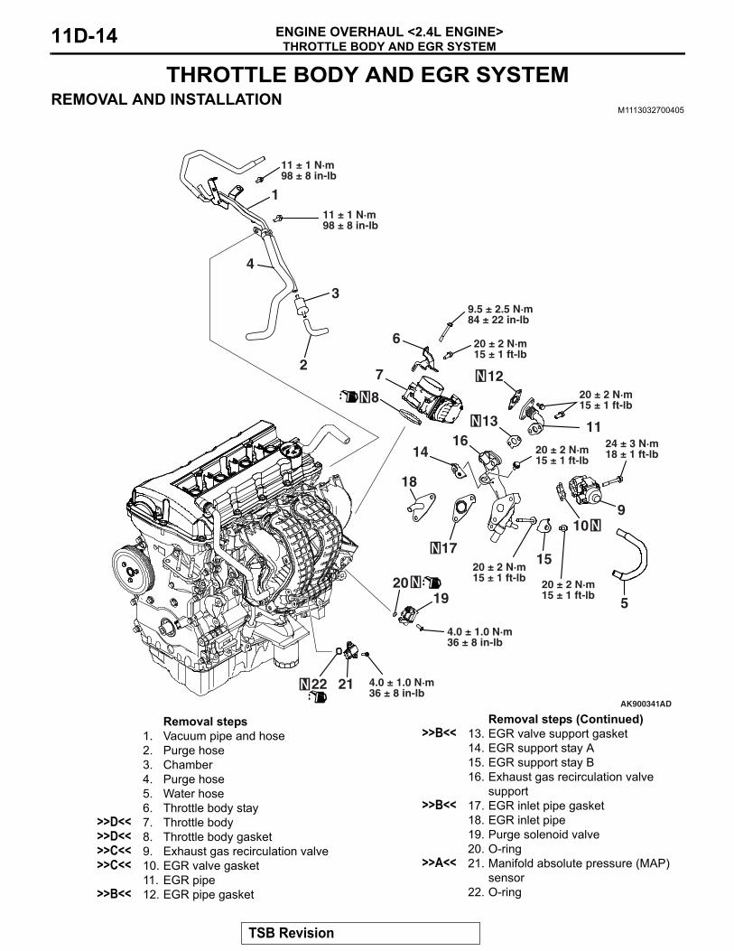
THROTTLE BODY AND EGR SYSTEMENGINE OVERHAUL <2.4L ENGINE>11D-14
THROTTLE BODY AND EGR SYSTEMREMOVAL AND INSTALLATION
M1113032700405
AK900341AD
910
11
12
15
1416
17
18
13
6
1920
1
2
3
4
11 ± 1 N·m98 ± 8 in-lb
2122
7
9.5 ± 2.5 N·m84 ± 22 in-lb
8
20 ± 2 N·m15 ± 1 ft-lb
4.0 ± 1.0 N·m36 ± 8 in-lb
5
20 ± 2 N·m15 ± 1 ft-lb
20 ± 2 N·m15 ± 1 ft-lb
20 ± 2 N·m15 ± 1 ft-lb
20 ± 2 N·m15 ± 1 ft-lb
24 ± 3 N·m18 ± 1 ft-lb
4.0 ± 1.0 N·m36 ± 8 in-lb
11 ± 1 N·m98 ± 8 in-lb
Removal steps 1. Vacuum pipe and hose2. Purge hose3. Chamber4. Purge hose5. Water hose6. Throttle body stay
>>D<< 7. Throttle body>>D<< 8. Throttle body gasket>>C<< 9. Exhaust gas recirculation valve>>C<< 10. EGR valve gasket
11. EGR pipe>>B<< 12. EGR pipe gasket
>>B<< 13. EGR valve support gasket14. EGR support stay A15. EGR support stay B16. Exhaust gas recirculation valve
CAUTION• Install the manifold absolute pressure (MAP) sensor,
taking care not to give a shock to it.• Do not use a manifold absolute pressure (MAP) sensor
that has fallen down..
>>B<< EGR INLET PIPE GASKET / EGR VALVE SUPPORT GASKET / EGR PIPE GASKET INSTALLATIONTemporarily tighten each part so that the protrusion of each gasket is positioned as illustrated.
.
>>C<< EXHAUST GAS RECIRCULATION VALVE / EXHAUST GAS RECIRCULATION VALVE GASKET INSTALLATION Install the Exhaust gas recirculation valve gasket with the diag-onally shaded area used as the illustrated position so as not to confuse the front with the back.
.
AK503321AC
EGR valve
Protrusion
EGR inlet pipe
AK503320AC
EGR valve pipe
Protrusion
Protrusion
AK503319AD
EGR valve
Shaded position
TSB Revision
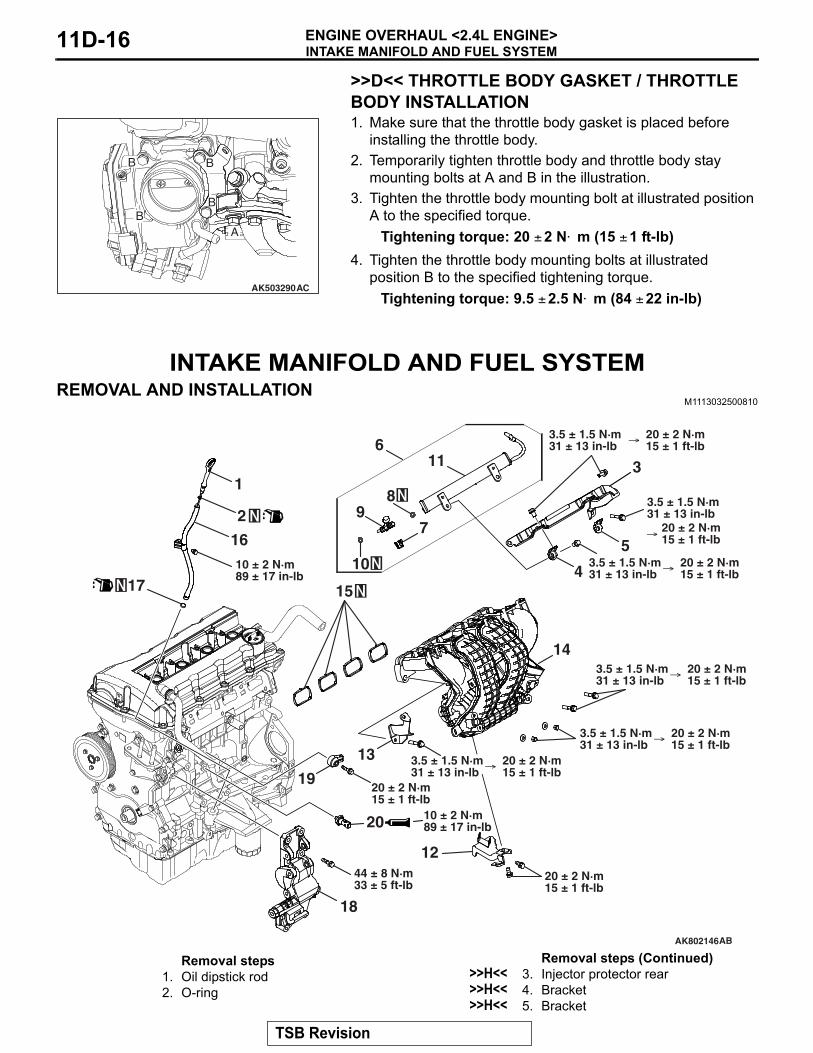
INTAKE MANIFOLD AND FUEL SYSTEMENGINE OVERHAUL <2.4L ENGINE>11D-16
>>D<< THROTTLE BODY GASKET / THROTTLE BODY INSTALLATION 1. Make sure that the throttle body gasket is placed before
installing the throttle body.2. Temporarily tighten throttle body and throttle body stay
mounting bolts at A and B in the illustration.3. Tighten the throttle body mounting bolt at illustrated position
A to the specified torque.Tightening torque: 20 ± 2 N⋅ m (15 ± 1 ft-lb)
4. Tighten the throttle body mounting bolts at illustrated position B to the specified tightening torque.
Tightening torque: 9.5 ± 2.5 N⋅ m (84 ± 22 in-lb)
INTAKE MANIFOLD AND FUEL SYSTEMREMOVAL AND INSTALLATION
>>B<< KNOCK SENSOR INSTALLATIONAlign the knock sensor connector with the position shown in the illustration, and then tighten it to the specified torque.
Tightening torque: 20 ± 2 N⋅ m (15 ± 1 ft-lb)
.
>>H<< 6. Fuel rail assembly>>G<< 7. Injection support
INTAKE MANIFOLD AND FUEL SYSTEMENGINE OVERHAUL <2.4L ENGINE>11D-18
>>C<< GENERATOR BRACKET INSTALLATIONTighten the Generator bracket to the specified tightening torque.
Tightening torque: 44 ± 8 N⋅ m (33 ± 5 ft-lb)NOTE: Be careful to install mounting bolts because they are different in length.
.
>>D<< INTAKE MANIFOLD INSTALLATIONCAUTION
Temporarily tighten the intake manifold because there is a bolt tightening procedure for the intake manifold, delivery pipe and injector protector.1. Tighten each intake manifold bolt and nut to the temporarily
2. Then tighten the intake manifold bolt and nut to specified torque.
Tightening torque: 20 ± 2 N⋅ m (15 ± 1 ft-lb).
>>E<< INTAKE MANIFOLD STAY INSTALLATIONMake sure that the intake manifold stay is in intimate contact with the intake manifold and cylinder block boss before tighten-ing it to the specified tightening torque.
Tightening torque: 20 ± 2 N⋅ m (15 ± 1 ft-lb)
.
>>F<< O-RING INSTALLATION 1. Apply gasoline to the O-ring.2. When inserting an O-ring into the injector on the injection
nozzle side, use special tool MB992106 to gradually expand the O-ring, and fit it in place.
.
AK503595AC
B
A
A
B
B
AA
A :M10 × 40 mm (1.6 in)B :M10 × 35 mm (1.4 in)
AK502727AC
AK600790
MB992106
O-ring
AC
TSB Revision
INTAKE MANIFOLD AND FUEL SYSTEMENGINE OVERHAUL <2.4L ENGINE> 11D-19
>>G<< INJECTOR AND INJECTOR SUPPORT INSTALLATION
CAUTIONDo not allow gasoline to enter the delivery pipe.1. Apply gasoline to the O-ring of the injector.2. Insert the injector into the delivery pipe while rotating the
injector from side to side, taking care not to damage the O-ring.
3. Check that the injector rotates smoothly. If it does not rotate smoothly, the O-ring may be caught. Remove the injector and check the O-ring for damage. Then, insert it again into the delivery pipe and check.
4. Make sure that the protrusion of the injector is at the center as shown in the illustration.
5. Securely assemble the injector to the injector groove and delivery pipe collar.
.
>>H<< FUEL RAIL ASSEMBLY / BRACKET / INJECTOR PROTECTOR REAR INSTALLATION1. Install the delivery pipe assembly, bracket and injector
protector rear on the cylinder head.Temporarily torque: 3.5 ± 1.5 N⋅ m (31 ± 13 in-lb)
2. Tighten mounting bolts together with temporarily tightened intake manifold mounting bolts in the order shown in the illustration.
3. Tighten the delivery pipe assembly, bracket, injector protector rear and intake manifold in the order shown in the illustration.
CAUTIONThe exhaust manifold gasket, washers and nuts must not be reused..
>>B<< CRANKSHAFT POSITION SENSOR / O-RING INSTALLATION
CAUTION• Do not apply a force such as torsion or twist to the
O-ring during assembly of the sensor.• Assemble the sensor, taking care not to give a shock to
it.• Do not use a sensor that has fallen down.
Tighten the crank angle sensor to the specified torque.Tightening torque: 11 ± 1 N⋅ m (98 ± 8 in-lb)
.
>>C<< EXHAUST MANIFOLD BRACKET INSTALLATION Make sure that exhaust manifold bracket A is in intimate con-tact with the exhaust manifold and cylinder block, and then tighten it to the specified tightening torque.
Tightening torque:M10: 41 ± 10 N⋅ m (30 ± 7 ft-lb)M8: 20 ± 5 N⋅ m (15 ± 3 ft-lb)
AK603560
Exhaust manifoldbracket B
Exhaust manifoldbracket D
Exhaust manifoldbracket A
AH
Crank angle sensorcover
TSB Revision
WATER HOSE AND PIPEENGINE OVERHAUL <2.4L ENGINE> 11D-23
WATER HOSE AND PIPEREMOVAL AND INSTALLATION
M1113032900476
AK802148
13 14
1
2
15
1819
16 1767
430 ± 9 N·m22 ± 6 ft-lb
53
89
10
11 12
AB
24 ± 3 N·m18 ± 1 ft-lb28 ± 8 N·m
21 ± 5 ft-lb
24 ± 3 N·m18 ± 1 ft-lb
11 ± 1 N·m98 ± 8 in-lb
11 ± 1 N·m98 ± 8 in-lb
24 ± 3 N·m18 ± 1 ft-lb
24 ± 3 N·m18 ± 1 ft-lb
24 ± 3 N·m18 ± 1 ft-lb
Removal steps 1. Water hose2. Water hose
>>C<< 3. Engine coolant temperature sensor4. Water outlet fitting5. Outlet fitting gasket6. Water inlet fitting
11.Water pipe gasket12.O-ring13.Water pump assembly14.Water pump gasket15.Engine hanger16.Camshaft position sensor17.O-ring18.Camshaft position sensor19.O-ring
Removal steps (Continued)
TSB Revision
WATER HOSE AND PIPEENGINE OVERHAUL <2.4L ENGINE>11D-24
INSTALLATION SERVICE POINTS.
>>A<< THERMOSTAT HOUSING / WATER PIPE ASSEMBLY INSTALLATIONAssemble the thermostat housing and water pipe, and tempo-rarily tighten them to the cylinder head and water pump. Then tighten them to the specified tightening.
Tightening torque: 24 ± 3 N⋅ m (18 ± 1 ft-lb).
>>B<< THERMOSTAT INSTALLATION Install the thermostat with the jiggle-valve facing almost straight upwards.
.
>>C<< ENGINE COOLANT TEMPERATURE SENSOR INSTALLATION
CAUTIONBe careful not to give a shock, twist and the like to the resin mold with a tool during installation.1. Apply an appropriate and minimum amount of sealant to the
coolant temperature sensor, taking care not to allow sealant to squeeze out.
Specified sealant:Three bond 1324N, LOCTITE 262 or equivalent
2. Tighten the coolant temperature sensor to the cylinder block to the specified tightening torque.
Tightening torque: 30 ± 9 N⋅ m (22 ± 6 ft-lb)
AK304916AC
Jiggle valve
AK502544 AD
TSB Revision
OIL PAN AND TIMING CHAIN CASEENGINE OVERHAUL <2.4L ENGINE> 11D-25
OIL PAN AND TIMING CHAIN CASEREMOVAL AND INSTALLATION
>>D<< 10.Cylinder head cover11.Cylinder head cover gasket12.Air compressor bracket
<<B>> >>C<< 13.Oil pan14.Engine support bracket
>>B<< 15.Front oil seal<<C>> >>A<< 16.Timing chain case
Removal steps (Continued)
TSB Revision
OIL PAN AND TIMING CHAIN CASEENGINE OVERHAUL <2.4L ENGINE>11D-26
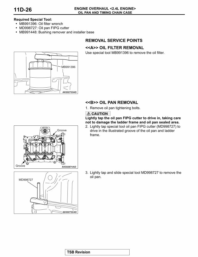
Required Special Tool:• MB991396: Oil filter wrench• MD998727: Oil pan FIPG cutter• MB991448: Bushing remover and installer base
REMOVAL SERVICE POINTS.
<<A>> OIL FILTER REMOVALUse special tool MB991396 to remove the oil filter.
.
<<B>> OIL PAN REMOVAL1. Remove oil pan tightening bolts.
CAUTIONLightly tap the oil pan FIPG cutter to drive in, taking care not to damage the ladder frame and oil pan sealed area.2. Lightly tap special tool oil pan FIPG cutter (MD998727) to
drive in the illustrated groove of the oil pan and ladder frame.
3. Lightly tap and slide special tool MD998727 to remove the oil pan.
.
AK502733AD
MB991396
AK502874AD
Groove
Groove
AK502732AD
MD998727
TSB Revision
OIL PAN AND TIMING CHAIN CASEENGINE OVERHAUL <2.4L ENGINE> 11D-27
<<C>> TIMING CHAIN CASE REMOVALIf the timing chain case is difficult to remove, insert a hammer handle as shown in the illustration and lightly pry it.
INSTALLATION SERVICE POINTS.
>>A<< TIMING CHAIN CASE INSTALLATIONCAUTION
• Be sure to remove the liquid gasket entering the mount-ing holes, the O-ring grooves and the cylinder gasket clearance.
• Sufficiently check whether there is no residual oil on the place where degreasing is performed using white gasoline, such as the surface where the FIPG is applied and stays, or the chamfered area.
• Do not touch the area where degreasing must be per-formed since the oils from your fingers will harm the seal ability.
1. Completely remove the liquid gasket adhering to the timing chain case, the cylinder block and the cylinder head.
2. Completely remove the sealant remaining on the 3-plane contact surface among the cylinder head, the cylinder block and the gasket.Carry out the degresing
AK502907
Hammer
AD
AK703733
AA
B-B view
A-A view D
AH
B A A
G C
C-C view
C
BB
7.5 ± 0.5 mm(0.30 ± 0.02 in)
3.0 ± 0.5 mm(0.12 ± 0.02 in)
2.5 mm(0.10 in)
1.0 ± 0.5 mm(0.04 ± 0.02 in)
Ø2.5 ± 0.5 mm(0.10 ± 0.02 in)
4.5 ± 0.5 mm(0.18 ± 0.02 in)
3.0 ± 0.5 mm(0.12 ± 0.02 in)
Ø2.5 ± 0.5 mm(0.10 ± 0.02 in)
Ø2.5 ± 0.5 mm(0.10 ± 0.02 in)
Ø4.5 ± 0.5 mm(0.18 ± 0.02 in)
Ø2.5 ± 0.5 mm(0.10 ± 0.02 in)
TSB Revision
OIL PAN AND TIMING CHAIN CASEENGINE OVERHAUL <2.4L ENGINE>11D-28
CAUTIONInstall the timing chain case within three minutes after applying the liquid gasket.3. Apply liquid gasket of 2.5 ± 0.5 mm (0.10 ± 0.02 inch) in
thickness to the timing chain case. For illustrated A locations, however, apply liquid gasket of 4.5 ± 0.5 mm (0.18 ± 0.02 inch) in diameter or liquid gasket of 2.5 ± 0.5 mm (0.10 ± 0.02 inch) by putting one on top of another as shown in the illustration.
Specified sealant:Three bond 1217G or exact equivalent
4. The engine oil staying at the cylinder gasket oozes to the 3-plane contact surface described in Step 2 and 3. Swiftly apply the liquid gasket to this area after degreasing.
Specified sealant:Three bond 1217G or exact equivalent
AK703734AD
TSB Revision
OIL PAN AND TIMING CHAIN CASEENGINE OVERHAUL <2.4L ENGINE> 11D-29
5. Tighten timing chain case mounting bolts to the specified tightening torque.
Tightening torqueA: 24 ± 4 N⋅ m (18 ± 2 ft-lb)B: 10 ± 2 N⋅ m (89 ± 17 in-lb)C: 10 ± 2 N⋅ m (89 ± 17 in-lb)D: 13 ± 1 N⋅ m (115 ± 8 in-lb)
.
>>B<< FRONT OIL SEAL INSTALLATION1. Apply engine oil to the internal circumference of the oil seal.2. Use special tool MB991448 to install the front oil seal on the
timing chain case.
.
>>C<< OIL PAN INSTALLATION1. Completely remove liquid gasket adhering to the cylinder
block and oil pan.2. Degrease the cylinder block and oil pan.
AK502378
A
A
A
A
AA
B
B
B B
B
B
C
D
AH
A: M8 × 30 mm (1.2 in)B: M6 × 25 mm (1.0 in)C: M6 × 25 mm (1.0 in)D: M8 × 10 mm (0.4 in)
AK800005
1.5 – 2.5 mm(0.06 – 0.09 in)
AC
MB991448
Chain case
Oil seal
MB991448
TSB Revision
OIL PAN AND TIMING CHAIN CASEENGINE OVERHAUL <2.4L ENGINE>11D-30
CAUTIONInstall the oil pan within three minutes after liquid gasket is applied.3. Apply liquid gasket of φ2.5 ± 0.5 mm (0.10 ± 0.02 inch) of
thickness in diameter to the illustrated area of the oil pan.Specified sealant:
Three bond 1217G or exact equivalent4. Tighten the oil pan to the specified tightening torque.
Tightening torque:M6:10 ± 2 N⋅ m (89 ± 17 in-lb)M8: 29 ± 2 N⋅ m (21 ± 1 ft-lb)
.
>>D<< CYLINDER HEAD COVER INSTALLATION1. Completely remove liquid gasket adhering to the cylinder
head cover, timing chain case and cylinder head.2. Degrease the cylinder head cover, timing chain case and
cylinder head.CAUTION
Install the cylinder head cover immediately after liquid gas-ket is applied.3. Appropriately use a minimum amount of sealant. Besides,
be careful not to allow sealant to squeeze out from the application area.Apply liquid gasket of 4 mm (0.16 inch) of thickness in diameter.
Specified sealant:Three bond 1217G or exact equivalent
4. Tighten the cylinder head cover to the tightening torque in the order shown in the illustration.
Tightening torque: 3.0 ± 1.0 N⋅ m (27 ± 8 in-lb)5. Then, tighten it to the specified tightening torque in the same
OIL PAN AND TIMING CHAIN CASEENGINE OVERHAUL <2.4L ENGINE> 11D-31
>>E<< OIL FILTER INSTALLATION1. Clean the oil filter mounting surface of the ladder frame.2. Apply engine oil to the O-ring of the oil filter.
CAUTIONUse special tool MB991396 to install the oil filter. Tighten-ing it by hand causes oil leakage due to lack of torque.3. Screw in the oil filter. When the O-ring contacts the mounting
surface, use a filter wrench to tighten it.Tightening torque3/4 turns (14 ± 2 N⋅ m [124 ± 17 in-lb])
<<A>> TIMING CHAIN TENSIONER REMOVAL1. Insert a flatblade screwdriver into the release hole of the
timing chain tensioner to release the latch.2. Push the tensioner lever by hand and push in the plunger of
the timing chain tensioner until it hits the bottom. Then, insert a hard wire (piano wire or the like) of φ1.5 or hexagonal bar wrench (1.5 mm [0.06 inch]) into the fixing hole of the plunger.
3. Remove the timing chain tensioner.
.
<<B>> EXHAUST V.V.T. SPROCKET BOLT REMOVALHold the hexagonal portion of the exhaust camshaft with a wrench and loosen the exhaust V.V.T. sprocket bolt.
.
<<C>> INTAKE V.V.T. SPROCKET BOLT REMOVALHold the hexagonal portion of the intake camshaft with a wrench and loosen the intake V.V.T. sprocket bolt.
AK502854AG
Wire
Ratchet release hole
Plunger fixedhole
AK502737
AK502736
TSB Revision
TIMING CHAINENGINE OVERHAUL <2.4L ENGINE>11D-34
INSTALLATION SERVICE POINTS.
>>A<< INTAKE V.V.T. SPROCKET BOLT INSTAL-LATION1. Assemble the intake V.V.T. sprocket assembly in the
following procedure.• Make sure that the knock pin of the inlet camshaft assembly
is positioned facing straight upward.• Apply an appropriate and minimum amount of engine oil to
the circumference of the tip of the intake V.V.T. sprocket assembly and the entire circumference of the area into which the intake V.V.T. sprocket assembly is inserted.
• Slowly insert the intake V.V.T. sprocket assembly into the normal position of the inlet camshaft assembly with its knock pin hole facing straight upward.
2. Install the V.V.T. sprocket.3. Make sure that the V.V.T. sprocket is securely inserted into
the bottom and that the V.V.T. sprocket does not rotate with the hexagonal portion of the camshaft secured with a wrench.
4. Hold the hexagonal portion of the camshaft with a wrench and tighten the intake V.V.T. sprocket bolt to the specified tightening torque.
Tightening torque: 59 ± 5 N⋅ m (44 ± 3 ft-lb)
.
>>B<< EXHAUST V.V.T. SPROCKET BOLT INSTALLATION1. Assemble the exhaust V.V.T. sprocket assembly in the
following procedure.• Make sure that the knock pin of the exhaust camshaft
assembly is positioned facing straight upward.• Apply an appropriate and minimum amount of engine oil to
the circumference of the tip of the exhaust V.V.T. sprocket assembly and the entire circumference of the area into which the exhaust V.V.T. sprocket assembly is inserted.
• Slowly insert the exhaust V.V.T. sprocket assembly into the normal position of the exhaust camshaft assembly with its knock pin hole facing straight upward.
2. Install the V.V.T. sprocket.3. Make sure that the V.V.T. sprocket is securely inserted into
the bottom and that the V.V.T. sprocket does not rotate with the hexagonal portion of the camshaft secured with a wrench.
AK503070AD
V.V.T. sprocket
V.V.T. sprocket boltCamshaft
AK502739
TSB Revision
TIMING CHAINENGINE OVERHAUL <2.4L ENGINE> 11D-35
4. Hold the hexagonal portion of the camshaft with a wrench and tighten the camshaft sprocket bolt to the specified tightening torque.
Tightening torque: 59 ± 5 N⋅ m (44 ± 3 ft-lb)
.
>>C<< TIMING CHAIN INSTALLATION1. Align the timing mark of the V.V.T. sprocket.2. Align the crankshaft sprocket keys with illustrated positions.
3. Align the link plate (orange) with the timing mark of the exhaust V.V.T. sprocket and loop the timing chain.
AK502738
AK502924
Timing mark
AD
Crankshaft key
AK502910AE
Timing markLink plate (orange)
TSB Revision
TIMING CHAINENGINE OVERHAUL <2.4L ENGINE>11D-36
4. Align the link plate (blue) with the timing mark of the intake V.V.T. sprocket to loop the timing chain. Rotate the intake V.V.T. sprocket by one or two teeth to align with the timing mark.
5. Align the timing mark of the crankshaft sprocket with the link plate (blue) to loop the timing chain. Because the timing chain slacks, hold it to prevent the timing mark from coming off the link plate.
6. Make sure that the timing mark of each sprocket is aligned with the link plate of the timing chain at all of three locations.
7. Install the timing chain guide and tensioner lever.
.
AK502757AG
Timing markLink plate(blue)
AK502735AGTiming mark
Link plate(blue)
AK502909
Timing marklink plate (blue)
Timing marklink plate (orange)
Timing marklink plate (blue)
CrankshaftsprocketTiming mark
V.V.T. intakesprockettiming mark
V.V.T. exhaustsprockettiming mark
AG
TSB Revision
TIMING CHAINENGINE OVERHAUL <2.4L ENGINE> 11D-37
>>D<< TIMING CHAIN TENSIONER INSTALLATION1. Install the timing chain tensioner on the cylinder block and
tighten it to the specified torque.Tightening torque: 10 ± 2 N⋅ m (89 ± 17 in-lb)
2. Remove the hard wire (piano wire or the like) of φ1.5 or hexagonal bar wrench (1.5 mm [0.05 inch]) from the timing chain tensioner. This enables the plunger of the timing chain tensioner to push the tensioner lever to keep the timing chain tight.
INSPECTION M1113026700871
INTAKE V.V.T. SPROCKETCAUTION
Never overhaul the V.V.T. sprocket.1. Seal with a tape all the intake camshaft ports for the
advanced angle and the retarded angle.2. Make a hole on the port for the advanced angle.
CAUTIONFix the camshaft on a vise not to damage it.3. Fixing the hexagonal area of the intake camshaft on a vise,
install the intake V.V.T. sprocket.
CAUTIONWhen applying air pressure, keep in mind that oil could splash.4. By applying air pressure slowly to the holed port for the
advanced angle, remove the stopper pin.5. Turn the intake V.V.T. sprocket housing in the right and left
directions. Check it smoothly moves in the range of A (approximately 20° )NOTE: The stopper pin is locked in the most retarded angle position.
6. .After the check, remove the intake V.V.T. sprocket from the intake camshaft
7. Completely remove the tape sealing the intake camshaft ports for the advanced angle and for the retarded angle.
AK502854AG
Wire
Ratchet release hole
Plunger fixedhole
AK800281AD
Make a hole
TapeRetardportAdvance
port
Advanceport
Retardport
AK800282AD
The hexagonalpart
AK800283
x
x
x-xADHousing
Stopper pin
A
TSB Revision
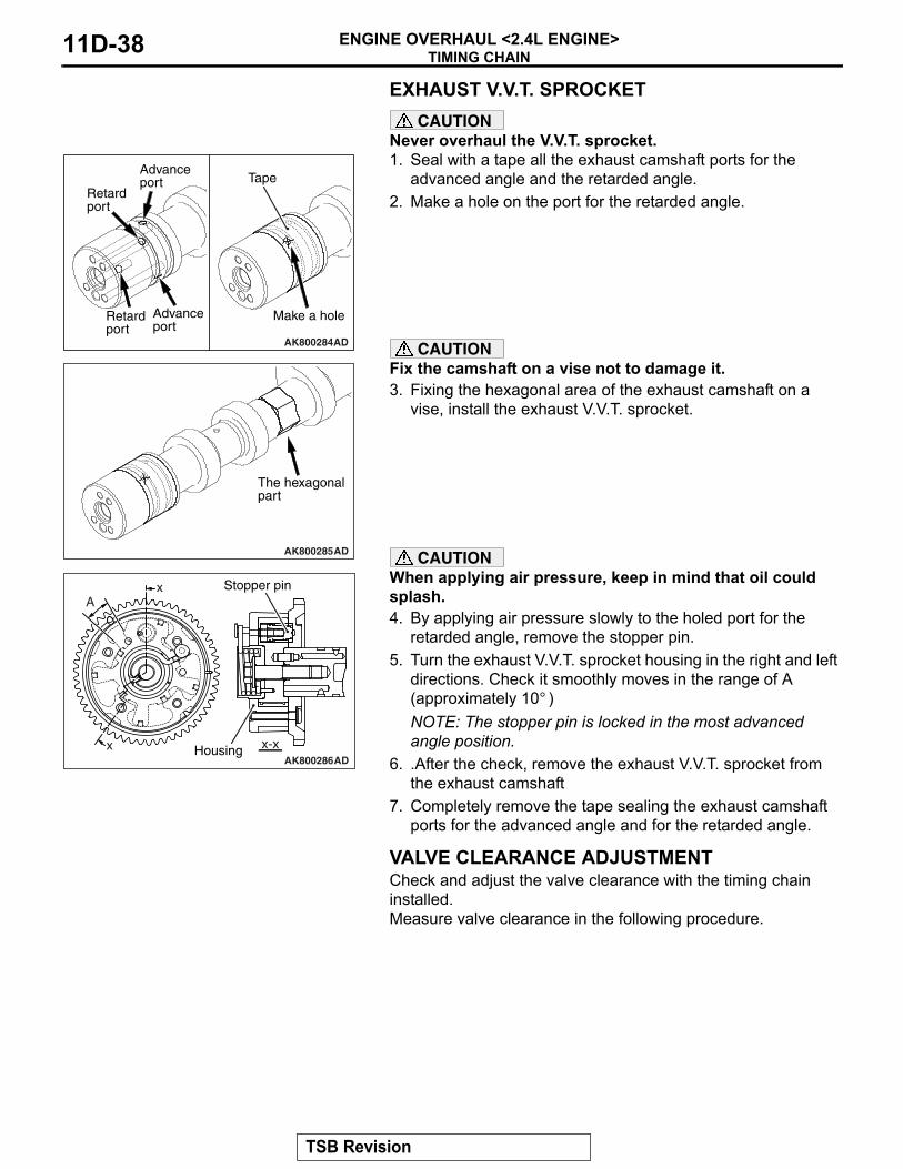
TIMING CHAINENGINE OVERHAUL <2.4L ENGINE>11D-38
EXHAUST V.V.T. SPROCKETCAUTION
Never overhaul the V.V.T. sprocket.1. Seal with a tape all the exhaust camshaft ports for the
advanced angle and the retarded angle.2. Make a hole on the port for the retarded angle.
CAUTIONFix the camshaft on a vise not to damage it.3. Fixing the hexagonal area of the exhaust camshaft on a
vise, install the exhaust V.V.T. sprocket.
CAUTIONWhen applying air pressure, keep in mind that oil could splash.4. By applying air pressure slowly to the holed port for the
retarded angle, remove the stopper pin.5. Turn the exhaust V.V.T. sprocket housing in the right and left
directions. Check it smoothly moves in the range of A (approximately 10° )NOTE: The stopper pin is locked in the most advanced angle position.
6. .After the check, remove the exhaust V.V.T. sprocket from the exhaust camshaft
7. Completely remove the tape sealing the exhaust camshaft ports for the advanced angle and for the retarded angle.
.
VALVE CLEARANCE ADJUSTMENTCheck and adjust the valve clearance with the timing chain installed.Measure valve clearance in the following procedure.
AK800284AD
Make a hole
TapeRetardport
Advanceport
Retardport
Advanceport
AK800285AD
The hexagonalpart
AK800286x
x
x-xAD
Housing
Stopper pinA
TSB Revision
TIMING CHAINENGINE OVERHAUL <2.4L ENGINE> 11D-39
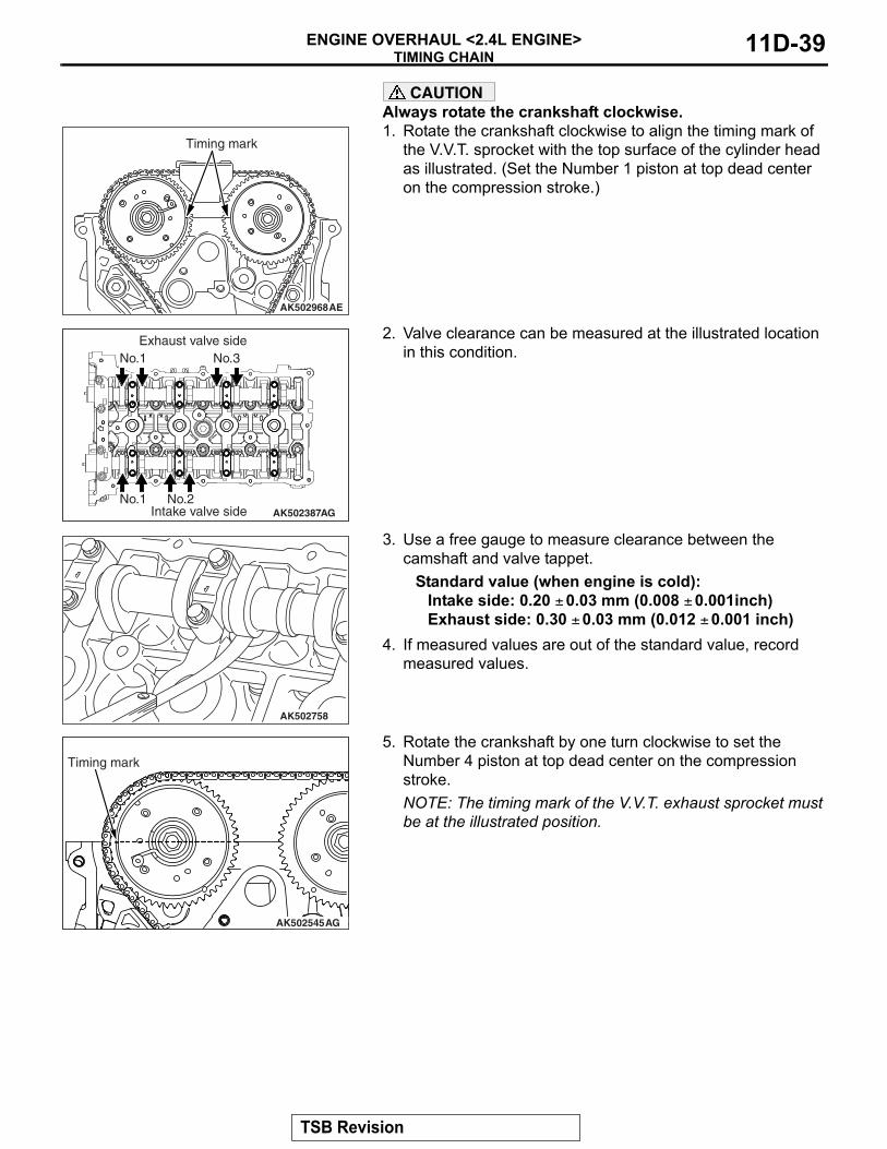
CAUTIONAlways rotate the crankshaft clockwise.1. Rotate the crankshaft clockwise to align the timing mark of
the V.V.T. sprocket with the top surface of the cylinder head as illustrated. (Set the Number 1 piston at top dead center on the compression stroke.)
2. Valve clearance can be measured at the illustrated location in this condition.
3. Use a free gauge to measure clearance between the camshaft and valve tappet.
Standard value (when engine is cold):Intake side: 0.20 ± 0.03 mm (0.008 ± 0.001inch)Exhaust side: 0.30 ± 0.03 mm (0.012 ± 0.001 inch)
4. If measured values are out of the standard value, record measured values.
5. Rotate the crankshaft by one turn clockwise to set the Number 4 piston at top dead center on the compression stroke.NOTE: The timing mark of the V.V.T. exhaust sprocket must be at the illustrated position.
AK502968AE
Timing mark
10
11
12
78
8
3
44
3
1
22
1
5
6
65
9
AK502387AGIntake valve sideNo.1 No.2
No.3Exhaust valve side
No.1
AK502758
AK502545AG
Timing mark
TSB Revision
TIMING CHAINENGINE OVERHAUL <2.4L ENGINE>11D-40
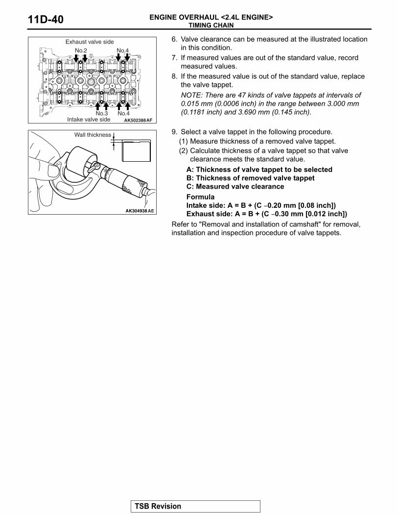
6. Valve clearance can be measured at the illustrated location in this condition.
7. If measured values are out of the standard value, record measured values.
8. If the measured value is out of the standard value, replace the valve tappet.NOTE: There are 47 kinds of valve tappets at intervals of 0.015 mm (0.0006 inch) in the range between 3.000 mm (0.1181 inch) and 3.690 mm (0.145 inch).
9. Select a valve tappet in the following procedure.(1) Measure thickness of a removed valve tappet.(2) Calculate thickness of a valve tappet so that valve
clearance meets the standard value.A: Thickness of valve tappet to be selectedB: Thickness of removed valve tappetC: Measured valve clearanceFormulaIntake side: A = B + (C − 0.20 mm [0.08 inch])Exhaust side: A = B + (C − 0.30 mm [0.012 inch])
Refer to "Removal and installation of camshaft" for removal, installation and inspection procedure of valve tappets.
<<A>> FRONT CAMSHAFT BEARING CAP / OIL FEEDING CAMSHAFT BEARING CAP / CAM-SHAFT BEARING CAP / THRUST CAMSHAFT BEARING CAP REMOVAL
CAUTIONLoosing the installation bolts for the camshaft bearing cap at the same time causes the valve spring force, which makes the installation bolts jump out, resulting in the dam-aged threads. Always loose them four or five times.First remove a mounting bolt of the front camshaft bearing cap and then a mounting bolt of each camshaft bearing cap in the order shown in the illustration.
.
<<B>> VALVE TAPPET REMOVALPick out valve tappets with fingers and store removed valve tappets with tags describing the installed position attached for reassembly.
INSTALLATION SERVICE POINTS.
>>A<< VALVE TAPPET INSTALLATIONInstall valve tappets at the same position based on tags describing the installed position for reassembly..
>>B<< CAMSHAFT / BEARING / THRUST CAMSHAFT BEARING CAP / CAMSHAFT BEARING CAP / OIL FEEDING CAMSHAFT BEARING CAP / FRONT CAMSHAFT BEARING CAP INSTALLATION1. When replacing a camshaft bearing, select a bearing with
the size corresponding to the identification mark in the table below.
2. Install camshaft bearings on the cylinder head.
AK502389AC
5
6
7810
2
15
67
812
3
4 9
910
11
1112
Camshaft Camshaft bearing
Identification mark
Journal diameter mm (in)
Identification mark
1 40.000 − 40.008(1.5748 − 1.5751)
1
2 40.008 − 40.016(1.5751 − 1.5754)
2
3 40.016 − 40.024(1.5754 − 1.5757)
3
AK502969AC
Identification mark
TSB Revision
CAMSHAFTENGINE OVERHAUL <2.4L ENGINE> 11D-43
3. The identification mark of the camshaft bearing is painted at the illustrated position.
4. Set the dowel pins of the camshaft at the illustrated positions.
5. Camshaft bearing caps Number 1 to Number 4 are of the same shape. Install them upon checking the identification mark so as not to misidentify cap Number and to confuse the intake side with the exhaust side.
Identification mark (stamped on front and Number 1 to Number 4 bearing caps)
I: Intake sideE: Exhaust side
6. Tighten each camshaft bearing cap mounting bolt to the specified torque in the order of number shown in the figure in two or three steps.
Tightening torque: 12 ± 1 N⋅ m (106 ± 8 in-lb)
AK702204
Notch
Identification mark
Oil hole AD
AK502390
Dowel pin
AC
AK503813
2E
Cap No.
1
2 6
5
2
1
6
5
AC
8
7
4
3
8
7
4
3
Identification mark
TSB Revision
CAMSHAFTENGINE OVERHAUL <2.4L ENGINE>11D-44
7. Tighten each front camshaft bearing cap mounting bolt to the temporarily torque of 17 ± 3 N⋅ m (14 ± 2 ft-lb) in the order of number shown (1).
8. Tighten each front camshaft bearing cap mounting bolt to the specified torque in the order shown (2).
Tightening torque: 30 ± 2 N⋅ m (22 ± 1 ft-lb)
.
>>C<< O-RING / ENGINE OIL CONTROL VALVE INSTALLATION
CAUTION• The O-ring must not be reused.• Wind non-adhesive tape (seal tape, etc.) around the
notch of the oil passage of the oil feeder control valve before installing the O-ring to prevent damage. Damage to the O-ring causes oil leakage.
1. Apply a small amount of engine oil to the O-ring of the oil feeder control valve.
2. Install the oil feeder control valve on the cylinder head.3. Tighten the oil feeder control valve to the specified
tightening torque of 10 ± 2 N⋅ m (89 ± 17 in-lb).
INSPECTIONM1113027000659
.
CAMSHAFTMeasure camshaft height (camshaft major axis). If the height exceeds the limit, replace the camshaft.
Standard value:Intake: 44.1 mm (1.74 inch)Exhaust: 45.0 mm (1.77 inch)
Limit:Intake: 43.6 mm (1.72 inch)Exhaust: 44.5 mm (1.75 inch)
.
AK503814
4
3
2
1
1
3
4
2
(1) (2)
AC
Timing chain side
AK303651AE
Tape
AK503020AC
TSB Revision
CAMSHAFTENGINE OVERHAUL <2.4L ENGINE> 11D-45
CAMSHAFT OIL CLEARANCE (PLASTIGAGE METHOD)1. Thoroughly wipe oil on the outside diameter of the camshaft
and the inside diameter of the bearing.2. Install the bearing to the camshaft.3. Put straightly the plastigage having the length of the bearing
width on the journal axis, centering the axis.4. Carefully install the bearing cap.Tighten the bolt as
instructed in >>B<< Bolt Installation Point.5. Remove the bolt and the bearing cap carefully.
6. Measure the plastigage whose width is most compressed using the scale printed on the plastigage bag. When the measured value deviates from the standard one, replace the bearing.
Standard value: 0 − 0.032 mm (0.0013 inch)
CAUTIONWhen the bearing is used again, be careful not to reverse the cylinder head side and the camshaft side at the instal-lation.
.
VALVE TAPPET1. Check the thickness stamp.
2. If the measured value in the table value is not in agreement with the value in the table to the thickness stamp, replace the valve tappet.There are 47 kinds of valve tappets at intervals of 0.015 mm (0.0006 inch) in the range between 3.000 (0.1181 inch) and 3.690 mm (0.1453 inch).
8. Valve spring retainer9. Valve spring10.Intake valve
<<A>> >>B<< 11.Retainer lock12.Valve spring retainer13.Valve spring14.Exhaust valve
<<B>> >>A<< 15.Valve stem seal<<B>> >>A<< 16.Valve stem seal
17.Intake valve guide18.Exhaust valve guide19.Intake valve seat20.Exhaust valve seat21.Cylinder head
Removal steps (Continued)
TSB Revision
CYLINDER HEAD AND VALVESENGINE OVERHAUL <2.4L ENGINE>11D-48
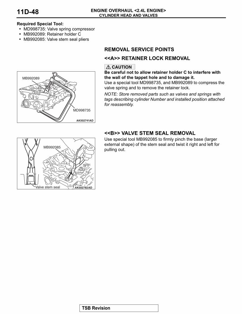
Required Special Tool:• MD998735: Valve spring compressor• MB992089: Retainer holder C• MB992085: Valve stem seal pliers
REMOVAL SERVICE POINTS.
<<A>> RETAINER LOCK REMOVALCAUTION
Be careful not to allow retainer holder C to interfere with the wall of the tappet hole and to damage it.Use a special tool MD998735, and MB992089 to compress the valve spring and to remove the retainer lock.NOTE: Store removed parts such as valves and springs with tags describing cylinder Number and installed position attached for reassembly.
.
<<B>> VALVE STEM SEAL REMOVALUse special tool MB992085 to firmly pinch the base (larger external shape) of the stem seal and twist it right and left for pulling out.
AK502741AD
MB992089
MD998735
AK502782ADValve stem seal
MB992085
TSB Revision
CYLINDER HEAD AND VALVESENGINE OVERHAUL <2.4L ENGINE> 11D-49
INSTALLATION SERVICE POINTS.
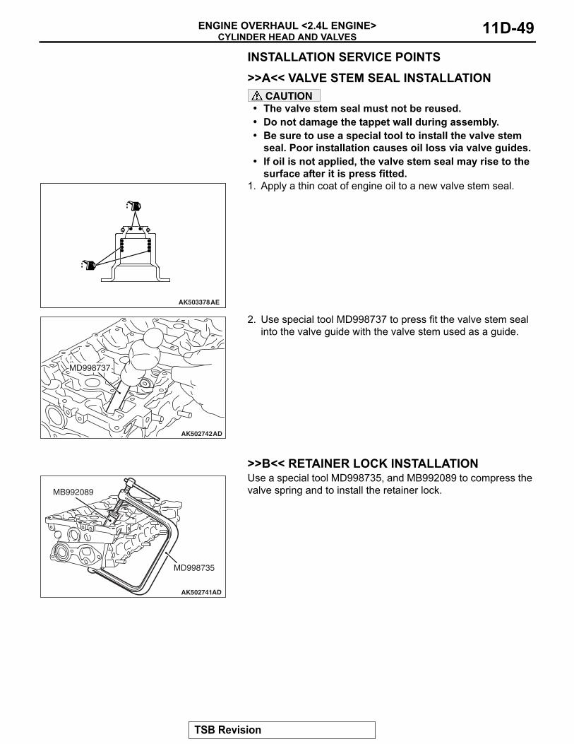
>>A<< VALVE STEM SEAL INSTALLATIONCAUTION
• The valve stem seal must not be reused.• Do not damage the tappet wall during assembly.• Be sure to use a special tool to install the valve stem
seal. Poor installation causes oil loss via valve guides.• If oil is not applied, the valve stem seal may rise to the
surface after it is press fitted.1. Apply a thin coat of engine oil to a new valve stem seal.
2. Use special tool MD998737 to press fit the valve stem seal into the valve guide with the valve stem used as a guide.
.
>>B<< RETAINER LOCK INSTALLATIONUse a special tool MD998735, and MB992089 to compress the valve spring and to install the retainer lock.
.
AK503378AE
AK502742AD
MD998737
AK502741AD
MB992089
MD998735
TSB Revision
CYLINDER HEAD AND VALVESENGINE OVERHAUL <2.4L ENGINE>11D-50
>>C<< CYLINDER HEAD GASKET / CYLINDER HEAD ASSEMBLY INSTALLATION1. Completely remove the liquid gasket on the upper plane of
the cylinder block and the lower plane of the cylinder head.CAUTION
Sufficiently check that there is no residual oil on the place where degreasing is performed. If fingerprints are left, do not touch it with bare hands after the degreasing, since the oils from your fingers will harm the seal ability.2. Degrease the place specified in the illustration.
3. As shown in the illustration, apply a 2.5 ± 0.5 mm (0.1 ± 0.02 inch) of sealant to the top face of cylinder block.
Specified sealant:Three bond 1217G or exact equivalent
4. Install the cylinder head gasket.NOTE: Check that the center of the liquid gasket is located toward the cylinder gasket in the position specified in the illustration.
5. As shown in the illustration, apply a 2.5 ± 0.5 mm (0.1 ± 0.02 inch) of sealant to the top face of cylinder head gasket.
Specified sealant:Three bond 1217G or exact equivalent
6. Install the cylinder head assembly.
.
AK602902AE
Top face of cylinder block
Degrease
Degrease
Bottom face of cylinder head
AK602942AD
Ø2 to Ø3 mm(0.079 to 0.118 in)
Timing chain side
TSB Revision
CYLINDER HEAD AND VALVESENGINE OVERHAUL <2.4L ENGINE> 11D-51
>>D<< CYLINDER HEAD BOLT INSTALLATION1. Install new cylinder head bolts and washers in the following
procedure.NOTE: Cylinder head bolts and washers must not be reused.
2. Apply an appropriate amount of engine oil to top and bottom surfaces of washers and threaded portion of bolts.
3. Install cylinder head bolts to the cylinder head.NOTE: Bolts and washers are different parts for bolts on the timing chain side.
4. Tighten cylinder head bolts in several steps to the specified torque according to the assembly order.
Tightening torque: 35 ± 2 N⋅ m (26 ± 1 ft-lb)
5. Put a paint mark on all of cylinder head bolt heads and cylinder head.CAUTION
• When the tightening angle is smaller than the specified tightening angle, the appropriate tightening capacity cannot be secured.
• When the tightening angle is larger than the specified tightening angle, remove the bolt to start from the beginning again according to the procedure.
6. Tighten the cylinder head 90° according to the tightening order.Tighten it further 90° and make sure that the paint mark on the cylinder head bolt is in a straight line with that on the cylinder head.
INSPECTIONM1113007002567
.
CYLINDER HEAD1. Check the cylinder head for water leakage, gas leakage,
damage or cracks before cleaning.2. Completely remove oil, scale, sealant, carbon, etc. After
cleaning oil passages, blow air to make sure that they are not clogged.
AK502392
8
10
9
7
3
5
1
2
6
4
AD
Timing chain side
AK502523AD
Paint mark Paint mark
90˚90˚
Paint mark Paint mark
TSB Revision
CYLINDER HEAD AND VALVESENGINE OVERHAUL <2.4L ENGINE>11D-52
CAUTIONThe grinding limit shall be within 0.2 mm (0.008 inch) in combination with the cylinder block to be assembled.3. For the flatness on the cylinder head bottom, measure
distortion using a straight edge and free gauge. If the distortion exceeds the limit, grind and repair it.
Distortion on bottomStandard value: Within 0.05 mm (0.002 inch)Limit: 0.2 mm (0.08 inch)Grinding limit: 0.2 mm (0.008 inch)
Cylinder head heightStandard value: 128.5 mm (5.06 inch)
.
VALVE1. Repair the valve seat if contact with the valve seat is poor,
uneven or broken.2. Measure the margin.
If the limit is exceeded, replace the valve.Standard value:
Intake 1.022 mm (0.0402 inch)Exhaust 1.094 mm (0.0431 inch)
Limit:Intake 0.522 mm (0.0206 inch)Exhaust 0.594 mm (0.0234 inch)
3. Measure overall length of the valve.If the limit is exceeded, replace the valve.
Standard value:Intake 113.18 mm (4.456 inch)Exhaust 105.89 mm (4.169 inch)
Limit:Intake 112.68 mm (4.436 inch)Exhaust 105.39 mm (4.149 inch)
.
VALVE SPRING1. Measure free height of the spring.
If the limit is exceeded, replace the spring.Standard value: 47.2 mm (1.858 inch)
2. Measure squareness of the spring.If the inclination exceeds the limit, replace the spring.
Standard value: 2° or lessLimit: 4°
.
AK502740
AK305408AD
Margin
The bottom of valveseat contact facet
AK305409AD
Length
AK305410AD
Free height
Squareness
TSB Revision
CYLINDER HEAD AND VALVESENGINE OVERHAUL <2.4L ENGINE> 11D-53
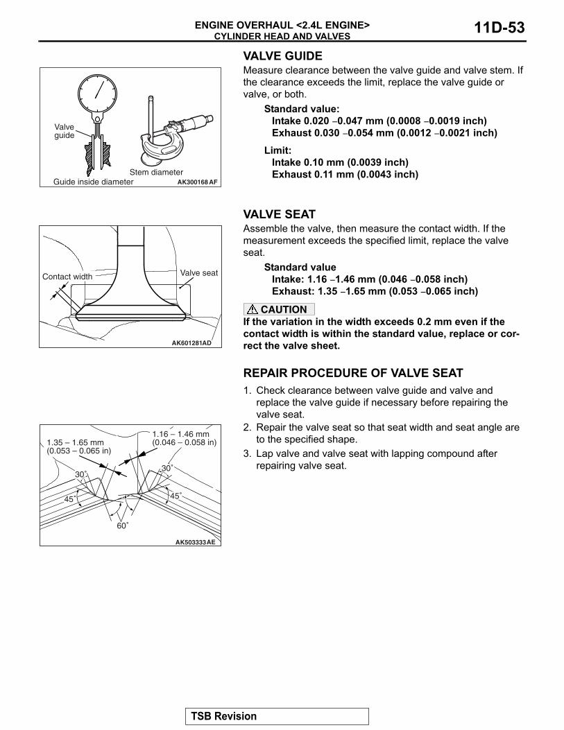
VALVE GUIDEMeasure clearance between the valve guide and valve stem. If the clearance exceeds the limit, replace the valve guide or valve, or both.
Standard value:Intake 0.020 − 0.047 mm (0.0008 − 0.0019 inch)Exhaust 0.030 − 0.054 mm (0.0012 − 0.0021 inch)
Limit:Intake 0.10 mm (0.0039 inch)Exhaust 0.11 mm (0.0043 inch)
.
VALVE SEATAssemble the valve, then measure the contact width. If the measurement exceeds the specified limit, replace the valve seat.
Standard valueIntake: 1.16 − 1.46 mm (0.046 − 0.058 inch)Exhaust: 1.35 − 1.65 mm (0.053 − 0.065 inch)
CAUTIONIf the variation in the width exceeds 0.2 mm even if the contact width is within the standard value, replace or cor-rect the valve sheet.
REPAIR PROCEDURE OF VALVE SEAT1. Check clearance between valve guide and valve and
replace the valve guide if necessary before repairing the valve seat.
2. Repair the valve seat so that seat width and seat angle are to the specified shape.
3. Lap valve and valve seat with lapping compound after repairing valve seat.
AK300168Guide inside diameterStem diameter
Valve guide
AF
AK601281AD
Contact width Valve seat
AK503333AE
30˚
60˚
30˚
1.16 – 1.46 mm(0.046 – 0.058 in)
45˚45˚
1.35 – 1.65 mm(0.053 – 0.065 in)
TSB Revision
CYLINDER HEAD AND VALVESENGINE OVERHAUL <2.4L ENGINE>11D-54
REPLACEMENT PROCEDURE OF VALVE SEAT1. Scrape the valve seat to be replaced from inside to make its
wall thickness thin before pulling out.
2. Repair the valve seat hole of the cylinder head to match it with the diameter of the oversize valve seat to be press fitted.
Intake valve seat bore diameter:0.3 Over size: 36.22 − 36.24 mm (1.426 − 1.427 inch)
Exhaust valve seat bore diameter:0.3 Over size: 30.22 − 30.24 mm (1.190 − 1.191 inch)
3. Press fit the valve seat, taking care not to score the cylinder head bore at room temperature.
4. Ream the valve seat.Refer to "Repair procedure of valve seat."
REPLACEMENT PROCEDURE OF VALVE GUIDE1. Pull out the valve guide with a press toward the cylinder
block side.2. Ream the valve guide hole of the cylinder head to match it
with the diameter of the oversize valve guide to be press fitted.CAUTION
Do not use a valve guide with the same size as that of the pulled out valve guide because it cannot be press fitted.
Valve guide bore diameter0.25 Over size: 11.23 − 11.25 mm (0.442 − 0.443 inch)
3. Press fit the valve guide to the illustrated dimension.Standard value: 14.6 − 15.2 mm (0.57 − 0.60 inch)
NOTE: Press fit the valve guide from the cylinder head top surface.
4. After pressing fit the valve guide, insert a new valve to check for sliding.
CAUTIONReliably secure the plunger of the chain tensioner with hard wire to prevent it from jumping out of the main body.1. Push in the balancer shaft tensioner lever by hand and push
in the plunger of the chain tensioner until it contacts the bottom. Then, insert hard wire (piano wire, etc.) of φ1.5 or hexagonal bar wrench (1.5 mm [0.06 inch]) into the plunger fixing hole to secure.
2. Remove the balancer shaft chain tensioner.
CAUTIONThe balancer shaft module must not be disassembled because of assembly warranty.3. Remove the crankshaft sprocket, balancer chain and
<<C>> LADDER FRAME REMOVAL1. Pry the illustrated position with a screwdriver or tap the boss
with a hammer.
2. If the ladder frame does not come off, insert a flatblade screwdriver into the gap between the ladder frame and bearing cap as shown in the illustration and lightly pry it to remove the ladder frame.
INSTALLATION SERVICE POINTS.
>>A<< LADDER FRAME INSTALLATIONCAUTION
Be sure to remove liquid gasket that has entered mounting holes.1. Completely remove liquid gasket adhering to the cylinder
block and ladder frame.CAUTION
Sufficiently check that there is no residual oil on the place where degreasing is performed. If fingerprints are left, do not touch it with bare hands after the degreasing, since the oils from your fingers will harm the seal ability.2. Degrease the surface where the liquid gasket is applied and
the contact surface between the cylinder block and ladder frame.
AK502755AD
Boss
AK502756
TSB Revision
BALANCER CHAINENGINE OVERHAUL <2.4L ENGINE>11D-58
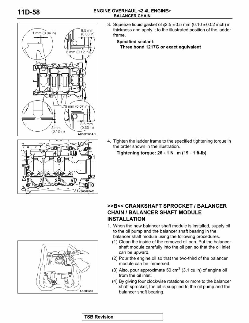
3. Squeeze liquid gasket of φ2.5 ± 0.5 mm (0.10 ± 0.02 inch) in thickness and apply it to the illustrated position of the ladder frame.
Specified sealant:Three bond 1217G or exact equivalent
4. Tighten the ladder frame to the specified tightening torque in the order shown in the illustration.
Tightening torque: 26 ± 1 N⋅ m (19 ± 1 ft-lb)
.
>>B<< CRANKSHAFT SPROCKET / BALANCER CHAIN / BALANCER SHAFT MODULE INSTALLATION1. When the new balancer shaft module is installed, supply oil
to the oil pump and the balancer shaft bearing in the balancer shaft module using the following procedures.(1) Clean the inside of the removed oil pan. Put the balancer
shaft module carefully into the oil pan so that the oil inlet can be upward.
(2) Pour the engine oil so that the two-third of the balancer module can be immersed.
(3) Also, pour approximate 50 cm3 (3.1 cu in) of engine oil from the oil inlet.
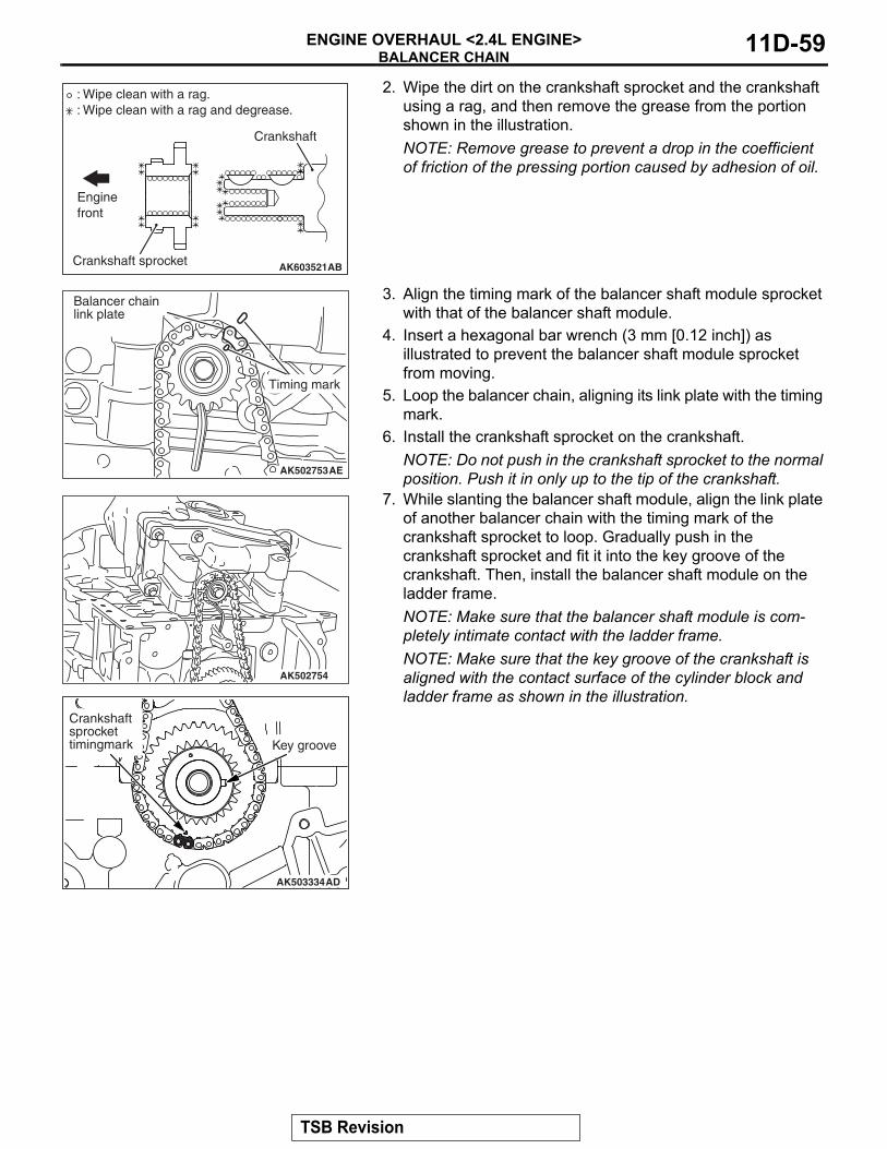
(4) By giving four clockwise rotations or more to the balancer shaft sprocket, the oil is supplied to the oil pump and the balancer shaft bearing.
2. Wipe the dirt on the crankshaft sprocket and the crankshaft using a rag, and then remove the grease from the portion shown in the illustration.NOTE: Remove grease to prevent a drop in the coefficient of friction of the pressing portion caused by adhesion of oil.
3. Align the timing mark of the balancer shaft module sprocket with that of the balancer shaft module.
4. Insert a hexagonal bar wrench (3 mm [0.12 inch]) as illustrated to prevent the balancer shaft module sprocket from moving.
5. Loop the balancer chain, aligning its link plate with the timing mark.
6. Install the crankshaft sprocket on the crankshaft.NOTE: Do not push in the crankshaft sprocket to the normal position. Push it in only up to the tip of the crankshaft.
7. While slanting the balancer shaft module, align the link plate of another balancer chain with the timing mark of the crankshaft sprocket to loop. Gradually push in the crankshaft sprocket and fit it into the key groove of the crankshaft. Then, install the balancer shaft module on the ladder frame.NOTE: Make sure that the balancer shaft module is com-pletely intimate contact with the ladder frame.NOTE: Make sure that the key groove of the crankshaft is aligned with the contact surface of the cylinder block and ladder frame as shown in the illustration.
AK603521Crankshaft sprocket
Crankshaft
AB
Enginefront
: Wipe clean with a rag.: Wipe clean with a rag and degrease.
AK502753AE
Timing mark
Balancer chainlink plate
AK502754
AK503334AD
Crankshaftsprockettimingmark Key groove
TSB Revision
BALANCER CHAINENGINE OVERHAUL <2.4L ENGINE>11D-60
8. Apply an appropriate and minimum amount of engine oil to the screw thread of the balancer shaft module bolt.
9. Tighten bolts to the specified tightening torque of 20 N⋅ m (14 ft-lb) according to the assembly order in the illustration, retighten them to 44 N⋅ m (32 ft-lb), and then completely loosen them.
10.After tightening them to the specified tightening torque of 20 N⋅ m again, use special tool MB991614 to tighten them up to 135° .
11.Pull out the hexagonal bar wrench from the balancer module sprocket.
12.Make sure that the respective timing mark is aligned with each other as illustrated.
13.Install the balancer chain tensioner lever and balancer chain guide.
.
>>C<< BALANCER SHAFT CHAIN TENSIONER INSTALLATION1. Attach the chain tensioner to the ladder frame.
CAUTIONInstall the chain tensioner precisely in place after installing the tensioner lever and chain guide to prevent the plunger of the chain tensioner from jumping out.2. Remove the hard wire (piano wire, etc.) of φ1.5 or hexagonal
bar wrench (1.5 mm [0.06 inch]) from the tensioner. This enables the plunger of the chain tensioner to push the balancer shaft tensioner lever to keep the balancer shaft chain tight.
.
>>D<< REAR OIL SEAL INSTALLATIONCAUTION
Do not apply oil to the circumference of the oil seal and oil seal pressing hole on the cylinder block side to prevent teeth from pulling out.After applying a small amount of engine oil to the oil seal lip, use special tool MD998718 to press fit the oil seal.
AK502923
Timing marklink plate
Timning marklink plate
Crank shaftsprockettiming mark
Key groove
Balancer shaftsprockettiming mark
AD
AK502940
AK502871AD
MD998718
TSB Revision
BALANCER CHAINENGINE OVERHAUL <2.4L ENGINE>11D-62
.
>>E<< DRIVE PLATE BOLT / FLYWHEEL BOLT INSTALLATION1. Clean off sealant and oil of thread of crankshaft and drive
plate bolts or flywheel bolts.2. Use special tool MB991883 to secure the drive plate or
flywheel bolts.
3. Apply engine oil to thread of crankshaft and bolt seat area of drive plate or flywheel bolts.
4. Apply the sealant to the thread of drive plate bolt or flywheel bolts.
Specified sealant:Three bond 1324 or equivalent
5. Tighten drive plate bolts or flywheel bolts to temporary torque of 40 N⋅ m (32 ft-lb) in the order shown to illustration.
6. Tighten drive plate bolts or flywheel bolts to specified tightening in the order shown in the illustration.
Tightening torque: 130 N⋅ m (95 ft-lb)
AK503335AD
MB991883
AK600847AE
AK603576
1 2
3
4
56
7
AB
TSB Revision
PISTON AND CONNECTING RODENGINE OVERHAUL <2.4L ENGINE> 11D-63
<<A>> >>F<< 2. Connecting rod cap>>E<< 3. Connecting rod bearing>>E<< 4. Connecting rod bearing>>D<< 5. Piston connecting rod assembly>>C<< 6. Piston ring Number 1
>>C<< 7. Piston ring Number 2>>B<< 8. Oil ring
<<B>> >>A<< 9. Piston pin10. Piston11. Connecting rod
Removal steps (Continued)
TSB Revision
PISTON AND CONNECTING RODENGINE OVERHAUL <2.4L ENGINE>11D-64
Required Special Tool:• MD998780: Piston pin setting tool• MB991659: Guide D• MD998718: Rear oil seal installer
REMOVAL SERVICE POINTS.
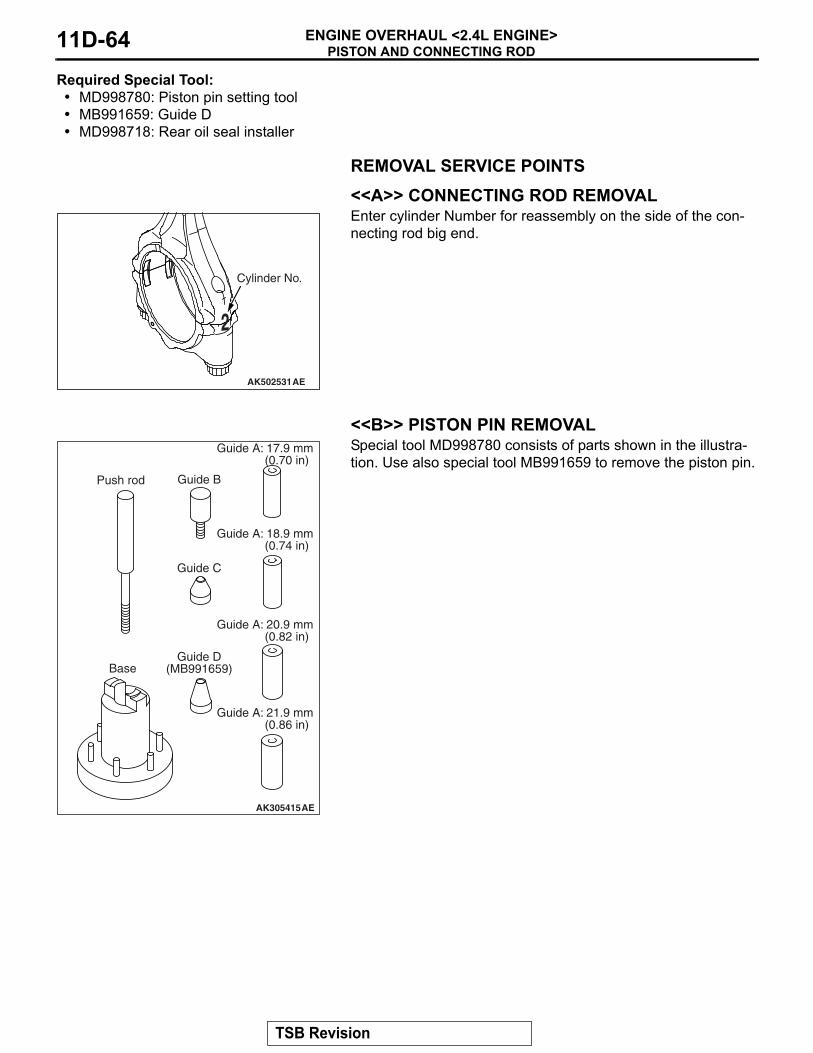
<<A>> CONNECTING ROD REMOVALEnter cylinder Number for reassembly on the side of the con-necting rod big end.
.
<<B>> PISTON PIN REMOVALSpecial tool MD998780 consists of parts shown in the illustra-tion. Use also special tool MB991659 to remove the piston pin.
AK502531AE
2
Cylinder No.
AK305415AE
Push rod
Base
Guide B
Guide C
Guide D(MB991659)
Guide A: 17.9 mm (0.70 in)
Guide A: 18.9 mm (0.74 in)
Guide A: 20.9 mm (0.82 in)
Guide A: 21.9 mm (0.86 in)
TSB Revision
PISTON AND CONNECTING RODENGINE OVERHAUL <2.4L ENGINE> 11D-65
1. Insert the push rod into the piston pin from the front mark side of the piston top surface, and attach special tool MB991659.
2. Set the piston and connecting rod assembly on the base so that the front mark of the piston faces upward.
3. Use a press to push the push rod and pull out the piston pin.NOTE: After pulling out the piston pin, organize pistons, pis-ton pins and connecting rods by cylinder Number
INSTALLATION SERVICE POINTS.
>>A<< PISTON PIN INSTALLATION1. When replacing a piston, check the cylinder bore size mark
stamped on the illustrated position of the cylinder block and select a corresponding piston from the table below.
A
AK502516AD
Base
Guide D
Pinston pin
Push rod
Front mark
Front mark
Cylinder bore size mark
Piston size mark
A A
B None
C CJ 2
J 3
J 4
J 5
J 1
AK503237
No.1
No.2
No.3
No.4
AD
TSB Revision
PISTON AND CONNECTING RODENGINE OVERHAUL <2.4L ENGINE>11D-66
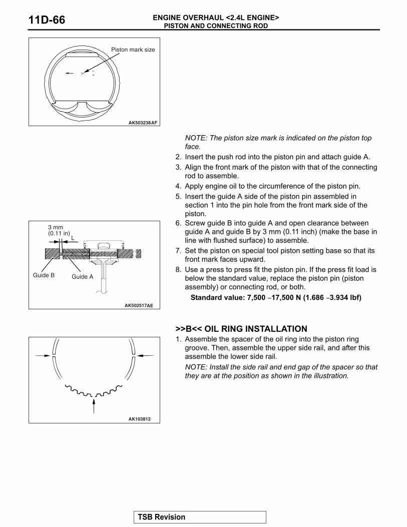
NOTE: The piston size mark is indicated on the piston top face.
2. Insert the push rod into the piston pin and attach guide A.3. Align the front mark of the piston with that of the connecting
rod to assemble.4. Apply engine oil to the circumference of the piston pin.5. Insert the guide A side of the piston pin assembled in
section 1 into the pin hole from the front mark side of the piston.
6. Screw guide B into guide A and open clearance between guide A and guide B by 3 mm (0.11 inch) (make the base in line with flushed surface) to assemble.
7. Set the piston on special tool piston setting base so that its front mark faces upward.
8. Use a press to press fit the piston pin. If the press fit load is below the standard value, replace the piston pin (piston assembly) or connecting rod, or both.
Standard value: 7,500 − 17,500 N (1.686 − 3.934 lbf)
.
>>B<< OIL RING INSTALLATION1. Assemble the spacer of the oil ring into the piston ring
groove. Then, assemble the upper side rail, and after this assemble the lower side rail.NOTE: Install the side rail and end gap of the spacer so that they are at the position as shown in the illustration.
A 24
AK503238AF
Piston mark size
AK502517AE
L
Guide A Guide B
3 mm(0.11 in)
AK103812
TSB Revision
PISTON AND CONNECTING RODENGINE OVERHAUL <2.4L ENGINE> 11D-67
CAUTIONThe side rail may be broken if its end gap is widened by a ring expander as in other piston rings.2. When assembling the side rail, push it by fingers, after fitting
one end of the side rail into the piston groove, for easy assembly.
3. After assembling the oil ring into the piston, make sure that the side rail turns smoothly to either direction.
.
>>C<< PISTON RING NUMBER. 2 / PISTON RING NUMBER. 1 INSTALLATIONUse a piston ring expander to assemble piston rings with their identification marks facing upward. Piston rings can be assem-bled by hand without using the piston ring expander.
>>D<< PISTON CONNECTING ROD ASSEMBLY INSTALLATION1. Apply a sufficient amount of engine oil to the circumference
of the piston, piston rings and oil ring.
AK304891
AK304892AD
Piston ringexpander
AK502529
Identification mark
No.1
No.2
AE
TSB Revision
PISTON AND CONNECTING RODENGINE OVERHAUL <2.4L ENGINE>11D-68
2. Arrange end gap positions of piston rings and oil ring (side rail and spacer) as shown in the illustration.
3. Insert the piston and connecting rod assembly from the top surface of the cylinder block with the front mark of the piston top face facing toward the timing belt side.
CAUTIONDriving it in hard causes breakage of piston rings and damage to the crank pin.4. Firmly tighten the piston ring with a ring band and insert the
piston and connecting rod assembly.
.
>>E<< CONNECTING ROD BEARING INSTALLATION1. When replacing a connecting rod bearing, select the bearing
corresponding to the crankshaft pin outside diameter according to the crankshaft pin identification in the table below.
2. An identification mark of a crankshaft is stamped at the illustrated position by Number
AK202730
No. 1
No. 2
Side rail
Side rail
AG
Piston pin
AK502730
Crankshaft pin Connecting rod bearing
Identification mark
Journal diameter mm (in)
Identification mark
1 47.966 − 47.972(1.8884 − 1.8886)
1
2 47.960 − 47.966(1.8882 − 1.8884)
2
3 47.954 − 47.960(1.8880 − 1.8881)
3
AK502527AD
No.1
No.2
No.3
No.4
Pin identification mark position
TSB Revision
PISTON AND CONNECTING RODENGINE OVERHAUL <2.4L ENGINE> 11D-69
3. A connecting rod bearing has an identification mark at the illustrated position.
.
>>F<< CONNECTING ROD CAP INSTALLATION NOTE: The connecting rod resulting from the breaking process has the high insertion force. The new connecting rod assembly may possibly be difficult to remove the connecting rod.If difficult to remove it, alternately strike the two bolt heads with a plastic hammer while the connecting rod bolt is slightly loos-ened, or strike the center of the cap shaft’s inside diameter slightly and outward.If the outside of the cap is directly struck, the lateral force is added to the broken-out section. Thus, pay attention to the bro-ken-out section that might be difficult to be separated or might fall.Clean the broken-out section before the installation to the engine, using compression air.1. Assemble the bearing cap on the connecting rod by aligning
it with the mark put during removal. If a new connecting rod without a mating mark is used, assemble so that the detent notch of the bearing is on the same side as illustrated.
2. Make sure that clearance of the thrust of the connecting rod big end is appropriate.
Standard value: 0.10 − 0.25 mm (0.004 − 0.010 inch)Limit: 0.4 mm (0.016 inch)
.
AK700793AD
Identificationmark
AK503157
2
Cylinder No.
AE
Notch
Front mark
AK502752
TSB Revision
PISTON AND CONNECTING RODENGINE OVERHAUL <2.4L ENGINE>11D-70
>>G<< CONNECTING ROD CAP BOLT INSTALLATION1. Check in the following procedure before reusing the
connecting rod bolt.(1) Measure the outside diameter "A."(2) Measure the smallest outside diameter "B" within the
range "X" shown in the illustration.(3) If the difference of outside diameter of thread exceeds
the limit, replace the connecting rod bolt.Limit: 0.1 mm (0.004 inch)
2. Apply engine oil to the threaded portion and seat surface of the bolt before installing it.
3. After installing each bolt and tightening it by fingers, tighten bolts alternately to properly assemble the cap.
4. Tighten the bolt in several steps until the torque reaches 5.0 N⋅ m (44 in-lb).
5. Tighten the bolt in several steps until the torque reaches 20 N⋅ m (14 ft-lb).
6. Put a paint mark on the bolt head as illustrated.7. Put a paint mark on the connecting rod at 90° position in the
tightening direction of the bolt with reference to the paint mark position of the bolt.CAUTION
• When the tightening angle is smaller than the specified tightening angle, the appropriate tightening capacity cannot be secured.
• When the tightening angle is larger than the specified tightening angle, remove the bolt to start from the beginning again according to the procedure.
8. Tighten the bolt 90° , and make sure that the paint mark of the connecting rod is aligned with that of the bolt.
INSPECTIONM1113008502123
.
PISTON RINGS1. Check clearance between piston rings and ring grooves. If
the limit is exceeded, replace piston rings or piston, or both.Standard value:
Number 1 ring: 0.03 − 0.07 mm (0.001 − 0.003 inch)Number 2 ring: 0.03 − 0.07 mm (0.001 − 0.003 inch)
Limit: 0.1 mm (0.004 inch)
AK604589AD
20.5 mm (0.81 in)
35 mm (1.38 in)
ABB
X
AK502749
90˚
Paint mark
AD
Paint mark
AK502751
TSB Revision
PISTON AND CONNECTING RODENGINE OVERHAUL <2.4L ENGINE> 11D-71
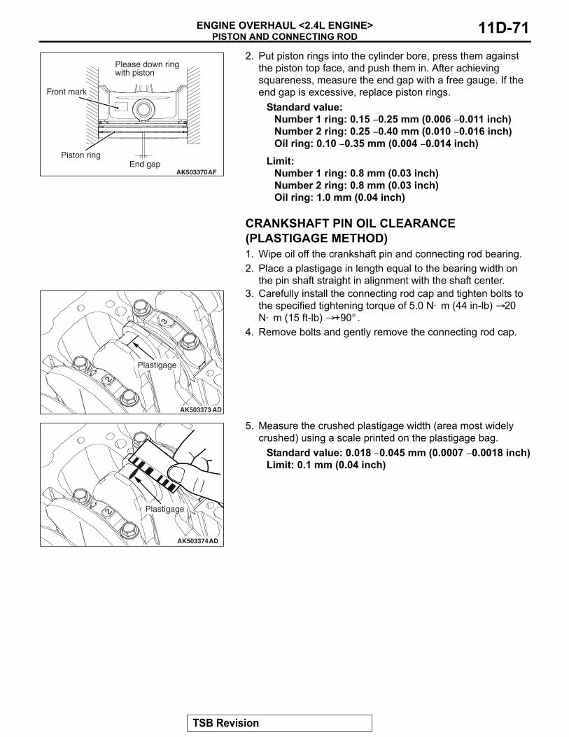
2. Put piston rings into the cylinder bore, press them against the piston top face, and push them in. After achieving squareness, measure the end gap with a free gauge. If the end gap is excessive, replace piston rings.
Standard value:Number 1 ring: 0.15 − 0.25 mm (0.006 − 0.011 inch)Number 2 ring: 0.25 − 0.40 mm (0.010 − 0.016 inch)Oil ring: 0.10 − 0.35 mm (0.004 − 0.014 inch)
Limit:Number 1 ring: 0.8 mm (0.03 inch)Number 2 ring: 0.8 mm (0.03 inch)Oil ring: 1.0 mm (0.04 inch)
.
CRANKSHAFT PIN OIL CLEARANCE (PLASTIGAGE METHOD)1. Wipe oil off the crankshaft pin and connecting rod bearing.2. Place a plastigage in length equal to the bearing width on
the pin shaft straight in alignment with the shaft center.3. Carefully install the connecting rod cap and tighten bolts to
the specified tightening torque of 5.0 N⋅ m (44 in-lb) → 20 N⋅ m (15 ft-lb) → +90° .
4. Remove bolts and gently remove the connecting rod cap.
5. Measure the crushed plastigage width (area most widely crushed) using a scale printed on the plastigage bag.
Standard value: 0.018 − 0.045 mm (0.0007 − 0.0018 inch)Limit: 0.1 mm (0.04 inch)
AK503370AF
Please down ring with piston
End gapPiston ring
Front mark
AK503373 AD
Plastigage
AK503374AD
Plastigage
TSB Revision
CRANKSHAFT AND CYLINDER BLOCKENGINE OVERHAUL <2.4L ENGINE>11D-72
CRANKSHAFT AND CYLINDER BLOCKREMOVAL AND INSTALLATION
CRANKSHAFT AND CYLINDER BLOCKENGINE OVERHAUL <2.4L ENGINE> 11D-73
REMOVAL SERVICE POINT.
<<A>> CRANKSHAFT REMOVALWhen temporarily placing the crankshaft with the crankshaft sensing ring attached, temporarily place it on a V-block to pre-vent teeth of the sensing ring from deforming.NOTE: If a tooth bends, be sure to replace the crankshaft sens-ing ring with a new one.
INSTALLATION SERVICE POINTS.
>>A<< CRANKSHAFT SENSING RING INSTALLA-TIONTighten crankshaft sensing ring bolts to specified torque in the tightening order shown in the illustration.
Tightening torque: 11 N⋅ m (98 ± 8 in-lb)
.
>>B<< THRUST BEARING INSTALLATION 1. Install the thrust bearing on the Number 3 bearing on the
cylinder block side. Application of engine oil makes the installation easy.
2. Install the thrust bearing so that the grooved side is on the crankshaft weight side.
.
AK502865AD
1
2
4 3
Crankshaft sensing ring
AK502394
Groove
AE
TSB Revision
CRANKSHAFT AND CYLINDER BLOCKENGINE OVERHAUL <2.4L ENGINE>11D-74
>>C<< CRANKSHAFT BEARING UPPER INSTALLATION1. When replacing the crankshaft bearing upper, select a
bearing with the size corresponding to the crankshaft journal diameter in the table below.
2. The crankshaft bearing upper has an identification mark at the illustrated position.
3. Install the selected crankshaft bearing upper..
Cylinder block Crankshaft bearing
Identification mark
Journal diameter mm (in)
Identification mark
1 56.000 − 56.006(2.2047 − 202049)
1
2 56.006 − 56.012(2.2050 − 2.2051)
2
3 56.012 − 56.018(2.2050 − 2.2054)
3
J 2
J 3
J 4
J 5
J 1
AK502530
No.1
No.2
No.3
No.4
No.5
AD
AK502396
Groove
AH
Identification mark
TSB Revision
CRANKSHAFT AND CYLINDER BLOCKENGINE OVERHAUL <2.4L ENGINE> 11D-75
>>D<< CRANKSHAFT BEARING LOWER INSTALLATION1. When replacing the crankshaft bearing lower, select a
bearing with the size corresponding to the crankshaft journal diameter in the table below.
2. The crankshaft bearing lower has an identification mark at the illustrated position.
3. Install the selected crankshaft bearing lower..
Crankshaft Crankshaft bearing
Identification mark
Journal diameter mm (in)
Identification mark
0 51.985 − 51.988(2.04665 − 2.04677)
0
1 51.982 − 51.985(2.04653 − 2.04665)
1
2 51.979 − 51.982(2.04641 − 2.04653)
2
3 51.976 − 51.979(2.04629 − 2.04641)
3
4 51.973 − 51.976(2.04618 − 2.04629)
4
AK502528AD
No.1
No.2
No.3
No.4
No.5
Journal identification mark position
AK502418AH
Identification mark
TSB Revision
CRANKSHAFT AND CYLINDER BLOCKENGINE OVERHAUL <2.4L ENGINE>11D-76
>>E<< CRANKSHAFT BEARING CAP / CRANKSHAFT BEARING CAP BOLT INSTALLATION1. Install the crankshaft bearing cap with reference to the
identification mark as illustrated.
2. Make sure that the underhead length of the bolt is at or below the limit before installing the crankshaft bearing cap bolt. If the length exceeds the limit, replace the bolt with a new one.
Limit: 75.5 − 76.5 mm (2.972 − 3.012 inch)3. Apply engine oil to the threaded portion and seat surface of
the bolt.4. Tighten crankshaft bearing cap bolts to specified torque
according to the tightening order.
CAUTION• When the tightening angle is smaller than the specified
tightening angle, the appropriate tightening capacity cannot be secured.
• When the tightening angle is larger than the specified tightening angle, remove the bolt to start from the beginning again according to the procedure.
5. Use special tool Angle gauge (MB991614) to tighten bolts 45° according to the tightening order.
AK502395
10
9
6
5 1
2 3
4
7
8
AD
AK402401AD
Shank length
AK502750
45˚
MB991614
AD
TSB Revision
CRANKSHAFT AND CYLINDER BLOCKENGINE OVERHAUL <2.4L ENGINE> 11D-77
6. Check end play of the crankshaft after installing the crankshaft bearing cap. If the end play exceeds the limit, replace the thrust bearing.
Standard value: 0.05 − 0.25 mm (0.002 − 0.010 inch)Limit: 0.4 mm (0.016 inch)
INSPECTIONM1113008802425
.
CRANKSHAFT OIL CLEARANCE (PLASTIGAGE METHOD)Oil clearance can be easily measured by using a "plastigage."When using a "plastigage," perform measurement in the follow-ing procedure.1. Fully wipe oil off the outside diameter of the crankshaft and
inside diameter of the bearing.2. Assemble the crankshaft.3. Place a plastigage in length equal to the bearing width on
the journal shaft straight in alignment with the shaft center.4. Carefully install the bearing cap and tighten the bolt
according to the main point of installation >>B<<.5. Remove the bolt, and then carefully remove the crankshaft
bearing cap.
6. Measure the crushed plastigage width (area most widely crushed) using a scale printed on the plastigage bag.
Standard value: 0.012 − 0.030 mm (0.0005 − 0.0012 inch)Limit: 0.08 mm (0.0031 inch)
.
AK503375
AK502747
AK502748
TSB Revision
CRANKSHAFT AND CYLINDER BLOCKENGINE OVERHAUL <2.4L ENGINE>11D-78
CYLINDER BLOCK1. Visually check the cylinder block for scratch, rust and
corrosion. Use a flaw detecting agent to check for cracks. If it is found faulty, repair or replace it.
2. Measure distortion on the top surface of the cylinder block using a straight edge and free gauge.If distortion exceeds the limit, grind and repair it.A gasket or the like must not be adhered to the top surface of the cylinder block during measurement.
Distortion on bottomStandars value: Within 0.05 mm (0.0020 inch)Limit: 0.2 mm (0.008 inch)Grinding limit: 0.2 mm (0.008 inch)
3. Check the cylinder wall for scratch or seizure. If there is any defect, replace the cylinder block.
4. Measure the bore and cylindricity of the cylinder using a cylinder gauge.If the cylinder is excessively worn, repair the cylinder and replace the piston and piston rings.Measuring points are as shown in the illustration.
Standard valueCylinder bore: 88 mm (3.46 inch)Cylindricity: 0.0076 mm (0.0003 inch)