The cooling system is a water-cooled pressurized, forced circulation type which offers the following fea-tures.• To stabilize engine coolant temperature, the ther-
mostat is located at the coolant inlet port from the radiator.
• To improve engine cooling performance and save weight, a plastic tank and aluminum radiator fins are used.
• The speed of the radiator fan is controlled by a fan controller. The engine control module (ECM) <M/T> or powertrain control module (PCM) <A/T> detects driving conditions and controls the controller so that the fan operating noise is mini-mized and fuel efficiency is improved.
CONSTRUCTION DIAGRAM
AC406330
RADIATOR
RADIATOR CONDENSERTANK ASSEMBLY
COOLING FAN MOTOR (LH)
AB
COOLING FAN SHROUD
<2.4L ENGINE>
COOLING FAN MOTOR (RH)
AC404969
RADIATORFAN MOTOR
RADIATOR
RADIATOR CONDENSERTANK ASSEMBLY
CONDENSOR FANSHROUD
TRANSMISSION FLUIDCOOLER LINE HOSE
FAN CONTROLLERAB
<3.8L ENGINE>
CONDENSOR FAN MOTOR
RADIATORFAN SHROUD
TSB Revision
SPECIAL TOOLENGINE COOLING 14-3
SPECIAL TOOLM1141000600440
TOOL TOOL NUMBER AND NAME
SUPERSESSION APPLICATION
MB991871
MB991871LLC changer
General service tool Coolant refilling
MB991223
A
D
C
B
AZ
DO NOT USE
MB991223 A: MB991219 B: MB991220 C: MB991221 D: MB991222 Harness set A: Test harness B: LED harness C: LED harness adapterD: Probe
General service tools Making voltage and resistance measurement during troubleshootingA: Connector pin contact
pressure inspectionB: Power circuit inspectionC: Power circuit inspectionD: Commercial tester
connection
MB992006
MB992006Extra fine probe
General service tool Making voltage and resistance measurement during troubleshooting
MB991923
MB991923Power plant ECU check harness
MD998478-01 Measurement of ECM <M/T> or PCM <A/T> terminal voltage
TSB Revision
ENGINE COOLING DIAGNOSISENGINE COOLING14-4
ENGINE COOLING DIAGNOSISINTRODUCTION
M1141005300381The system cools the engine so that it does not over-heat and maintains the engine at an optimum tem-perature. The system components are the radiator, water pump, thermostat, condenser fan assembly. Possible faults include low coolant, contamination, belt loosening and component damage.
TROUBLESHOOTING STRATEGYM1141005200373
Use these steps to plan your diagnostic strategy. If you follow them carefully, you will be sure to find most of the engine cooling faults.1. Gather information from the customer.
2. Verify that the condition described by the customer exists.
3. Find and repair the malfunction by following the SYMPTOM CHART.
4. Verify that the malfunction is eliminated.
SYMPTOM CHARTM1141005600490
SYMPTOM INSPECTION PROCEDURE
REFERENCE PAGE
Coolant Leak 1 P.14-5Engine Overheating 2 P.14-6Radiator Fan and Condenser Fan do not Operate <3.8L Engine> 3 P.14-7Radiator Fan and Condenser Fan do not Change Speed or Stop <3.8L Engine>
4 P.14-14
Radiator Fan does not Operate <3.8L Engine> 5 P.14-20Condenser Fan does not Operate <3.8L Engine> 6 P.14-20
TSB Revision
ENGINE COOLING DIAGNOSISENGINE COOLING 14-5
SYMPTOM PROCEDURES
INSPECTION PROCEDURE 1: Coolant Leak
DIAGNOSIS
STEP 1. Check for coolant leaks.WARNING
When pressure testing the cooling system, slowly release cooling system pressure to avoid getting burned by hot coolant.
CAUTION• Be sure to completely clean away any moisture from
the places checked.• When the tester is removed, be careful not to spill any
coolant.• When installing and removing the tester and when test-
ing, be careful not to deform the filler neck of the radia-tor.
ACX01844 AB
CAP ADAPTER
ADAPTER
Check that the coolant level is up to the filler neck. Install a radi-ator tester and apply 160 kPa (23 psi) pressure, and then check for leakage from the radiator hose or connections.Q: Is leakage present from the radiator hose or
connections?YES : Repair or replace the appropriate part, then go to
Step 2.NO : There is no action to be taken.
STEP 2. Retest the system.Q: It there still coolant leakage?
YES : Return to Step 1.NO : The procedure is complete.
TSB Revision
ENGINE COOLING DIAGNOSISENGINE COOLING14-6
INSPECTION PROCEDURE 2: Engine Overheating
DIAGNOSIS
STEP 1. Remove the radiator cap and check for coolant contamination.Q: Is the coolant contaminated with rust and oil?
YES : Replace it. Refer to P.14-22.NO : There is no action to be taken. Go to Step 2.
STEP 2. Check the radiator cap valve opening pressure.NOTE: Be sure that the cap is clean before testing. Rust or other foreign material on the cap seal will cause an improper reading.
ACX01845 AB
CAP ADAPTER
(1) Use a cap adapter to attach the cap to the tester.(2) Increase the pressure until the gauge indicator stops
Q: Does the reading remain at or above the minimum limit?YES : Go to Step 3.NO : Replace the radiator cap. Then go to Step 5.
STEP 3. Check thermostat operation.Refer to P.14-33.Q: Does the thermostat operate correctly?
YES : Go to Step 4.NO : Replace the thermostat, then go to Step 5.
STEP 4. Check the drive belt for slippage or damage.Refer to GROUP 00, Maintenance Service − Drive Belts (for Generator, Power Steering Pump And Air Conditioning) (Check) P.00-52.Q: Is the drive belt loose or damaged?
YES : Adjust or replace the drive belt, then go to Step 5.NO : There is no action to be taken.
STEP 5. Retest the system.Check the engine coolant temperature.Q: Is the engine coolant temperature abnormally high?
YES : Return to Step 2.NO : The procedure is complete.
TSB Revision
ENGINE COOLING DIAGNOSISENGINE COOLING 14-7
INSPECTION PROCEDURE 3: Radiator Fan and Condenser Fan do not Operate <3.8L Engine>
Radiator Fan and Condenser Fan Drive Circuit
ECM <M/T>ORPCM <A/T>
FANCONTROLMODULE
MFIRELAY
FUSIBLELINK
CONDENSERFAN MOTOR
RADIATORFAN MOTOR
FANCONTROLRELAY
23
AC407060AH
A-12X
FUSIBLE LINK (23) ANDCONNECTORS: A-12X, B-16X
FUSIBLE LINK (23)
B-16X
AC406432AF
CONNECTOR: A-15
A-15 (GR)
TSB Revision
ENGINE COOLING DIAGNOSISENGINE COOLING14-8
AC204370
A-22
A-22-1
CONNECTORS: A-22, A-22-1
FAN CONTROL MODULE
AI AC406995
CONNECTOR: B-18 B-18 (B)
AIRCLEANER
ECM <M/T> OR PCM <A/T>
AC
.
CIRCUIT OPERATION• The fan control module is powered from fusible
link number 23.• The ECM <M/T> or PCM <A/T> judges the
required revolution speed of radiator fan motor and condenser fan motor using the input signals transmitted from A/C switch, automatic compres-sor controller, vehicle speed sensor and engine coolant temperature sensor. The ECM <M/T> or PCM <A/T> activates the fan control module to drive the radiator fan motor and condenser fan motor.
.
TECHNICAL DESCRIPTION• The cause could be a malfunction of the fan con-
trol module power supply or ground circuit.• The cause could also be a malfunction of the fan
control module or the ECM <M/T> or PCM <A/T>..
TROUBLESHOOTING HINTS• Malfunction of fusible link• Malfunction of fan control relay• Malfunction of MFI relay• Malfunction of fan control module• Malfunction of ECM <M/T> or PCM <A/T>• Damaged wiring harness or connector
DIAGNOSISRequired Special Tools:• MB992006: Extra Fine Probe• MB991223: Harness Set• MB991923: Power Plant ECU Check Harness
TSB Revision
ENGINE COOLING DIAGNOSISENGINE COOLING 14-9
STEP 1. Check the circuit at fan control module connector A-22 (terminal 3).
AC204370
A-22
CONNECTOR: A-22
AJ
(1) Disconnect fan control module connector A-22, and measure at the harness side connector.
3 2 1
AC201418AI
A-22 HARNESS CONNECTOR:COMPONENT SIDE
(2) Measure the voltage between terminal number 3 and ground.
• When the ignition switch is turned to the "ON" position, voltage should measure battery positive voltage.
Q: Is there voltage battery positive voltage when the ignition switch is turned to the "ON" position?YES : Go to Step 8.NO : Go to Step 2.
STEP 2. Check the fan control relay. Refer to P.14-24.Q: Is the fan control relay in good condition?
YES : Go to Step 3.NO : Replace it, then go to Step 1.
STEP 3. Check the MFI relay. Refer to P.13B-1283.Q: Is the MFI relay in good condition?
YES : Go to Step 4.NO : Replace it, then go to Step 1.
STEP 4. Check for harness damage between fusible link number 23 and fan control relay connector A-12X (terminal 4).
AC407060AI
A-12X
FUSIBLE LINK (23) ANDCONNECTOR: A-12X
FUSIBLE LINK (23)
3
14 2
RELAY BOX SIDE
FRONT OF VEHICLE
Q: Are the harness wires between fusible link number 23 and fan control relay connector A-12X damaged? YES : Repair or replace them, then go to Step 14.NO : Go to Step 5.
TSB Revision
ENGINE COOLING DIAGNOSISENGINE COOLING14-10
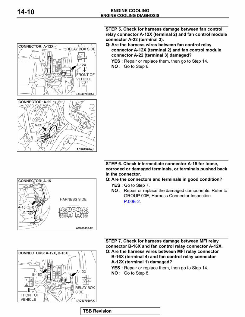
STEP 5. Check for harness damage between fan control relay connector A-12X (terminal 2) and fan control module connector A-22 (terminal 3).
AC407060AJ
A-12X
CONNECTOR: A-12X
3
14 2
RELAY BOX SIDE
FRONT OF VEHICLE
AC204370
A-22
CONNECTOR: A-22
AJ
Q: Are the harness wires between fan control relay connector A-12X (terminal 2) and fan control module connector A-22 (terminal 3) damaged?YES : Repair or replace them, then go to Step 14.NO : Go to Step 6.
STEP 6. Check intermediate connector A-15 for loose, corroded or damaged terminals, or terminals pushed back in the connector.
AC406432AE
CONNECTOR: A-15
HARNESS SIDE
A-15 (GR)
Q: Are the connectors and terminals in good condition?YES : Go to Step 7.NO : Repair or replace the damaged components. Refer to
GROUP 00E, Harness Connector Inspection P.00E-2.
STEP 7. Check for harness damage between MFI relay connector B-16X and fan control relay connector A-12X.
AC407060AK
A-12X
CONNECTORS: A-12X, B-16X
3
14 2
RELAY BOX SIDE
FRONT OF VEHICLE
1 3
2 4
B-16X
Q: Are the harness wires between MFI relay connector B-16X (terminal 4) and fan control relay connector A-12X (terminal 1) damaged?YES : Repair or replace them, then go to Step 14.NO : Go to Step 8.
TSB Revision
ENGINE COOLING DIAGNOSISENGINE COOLING 14-11
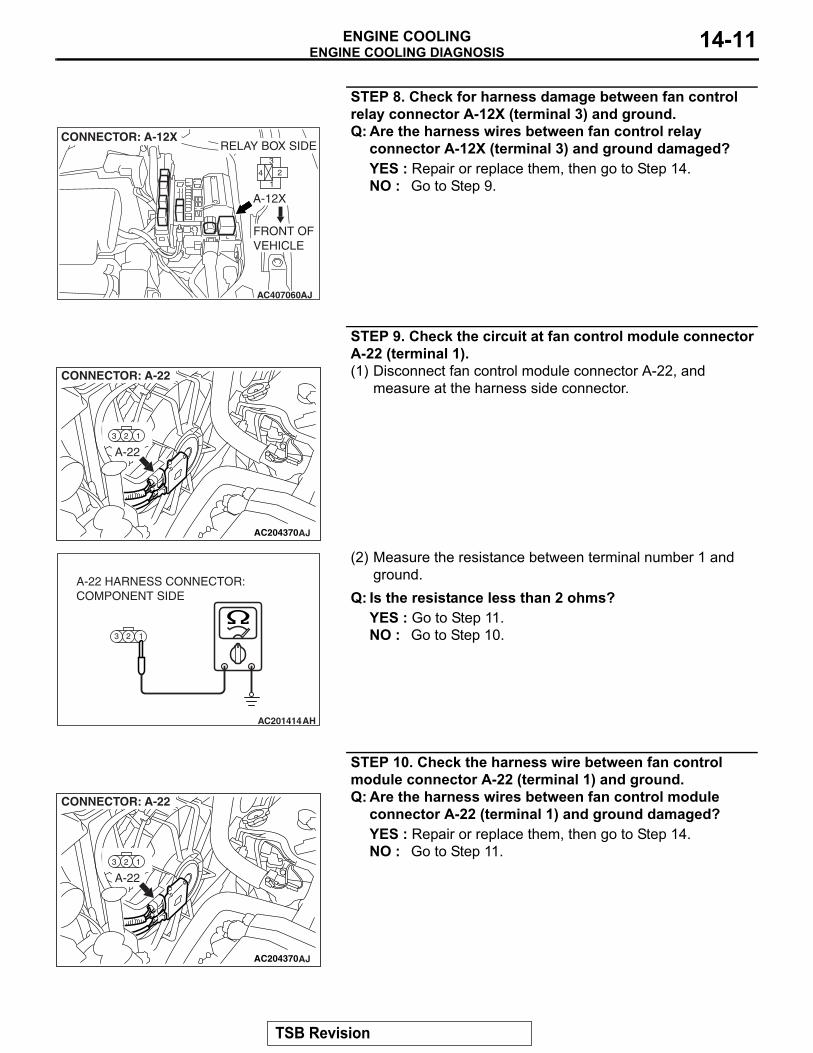
STEP 8. Check for harness damage between fan control relay connector A-12X (terminal 3) and ground.
AC407060AJ
A-12X
CONNECTOR: A-12X
3
14 2
RELAY BOX SIDE
FRONT OF VEHICLE
Q: Are the harness wires between fan control relay connector A-12X (terminal 3) and ground damaged?YES : Repair or replace them, then go to Step 14.NO : Go to Step 9.
STEP 9. Check the circuit at fan control module connector A-22 (terminal 1).
AC204370
A-22
CONNECTOR: A-22
AJ
(1) Disconnect fan control module connector A-22, and measure at the harness side connector.
3 2 1
AC201414
A-22 HARNESS CONNECTOR:COMPONENT SIDE
AH
(2) Measure the resistance between terminal number 1 and ground.
Q: Is the resistance less than 2 ohms?YES : Go to Step 11.NO : Go to Step 10.
STEP 10. Check the harness wire between fan control module connector A-22 (terminal 1) and ground.
AC204370
A-22
CONNECTOR: A-22
AJ
Q: Are the harness wires between fan control module connector A-22 (terminal 1) and ground damaged?YES : Repair or replace them, then go to Step 14.NO : Go to Step 11.
TSB Revision
ENGINE COOLING DIAGNOSISENGINE COOLING14-12
STEP 11. Measure the output circuit voltage at ECM <M/T> or PCM <A/T> connector B-18 (terminal 10) by using check harness special tool MB991923.
AC406993AC
B-18 (B)
CONNECTOR: B-18
ECM <M/T> OR PCM <A/T>
AIRCLEANER
B-18 HARNESSCONNECTOR:COMPONENT SIDE
(1) Disconnect all the connectors from the ECM <M/T> or PCM <A/T>.
AC209793AS
ECM <M/T> OR PCM <A/T>
MB991923
BODY SIDEHARNESS
SPECIAL TOOL 18-PIN CONNECTOR(ECM <M/T> OR PCM <A/T> CONNECTOR B-18)
B-18 (GR)
(2) Connect special tool MB991923 (check harness) between the ECM <M/T> or PCM <A/T> and the body-side harness connector.
(3) Start the engine and allow it to idle.
TSB Revision
ENGINE COOLING DIAGNOSISENGINE COOLING 14-13
AC210072AB
SPECIAL TOOL 18-PINCONNECTOR:COMPONENT SIDE
(4) Measure the voltage between terminal number 10 and ground.
Q: Is the voltage 0.7 volt or more when the radiator fan is operating?YES : Go to Step 13.NO : Go to Step 12.
STEP 12. Check the harness wire between ECM <M/T> or PCM <A/T> connector B-18 and fan control module connector A-22.
AC204370
A-22
CONNECTOR: A-22
AJ
AC406993AC
B-18 (B)
CONNECTOR: B-18
ECM <M/T> OR PCM <A/T>
AIRCLEANER
B-18 HARNESSCONNECTOR:COMPONENT SIDE
Q: Are the harness wires between ECM <M/T> or PCM <A/T> connector B-18 (terminal 10) and fan control module connector A-22 (terminal 2) damaged?YES : Repair or replace them, then go to Step 14.NO : Go to Step 13.
TSB Revision
ENGINE COOLING DIAGNOSISENGINE COOLING14-14
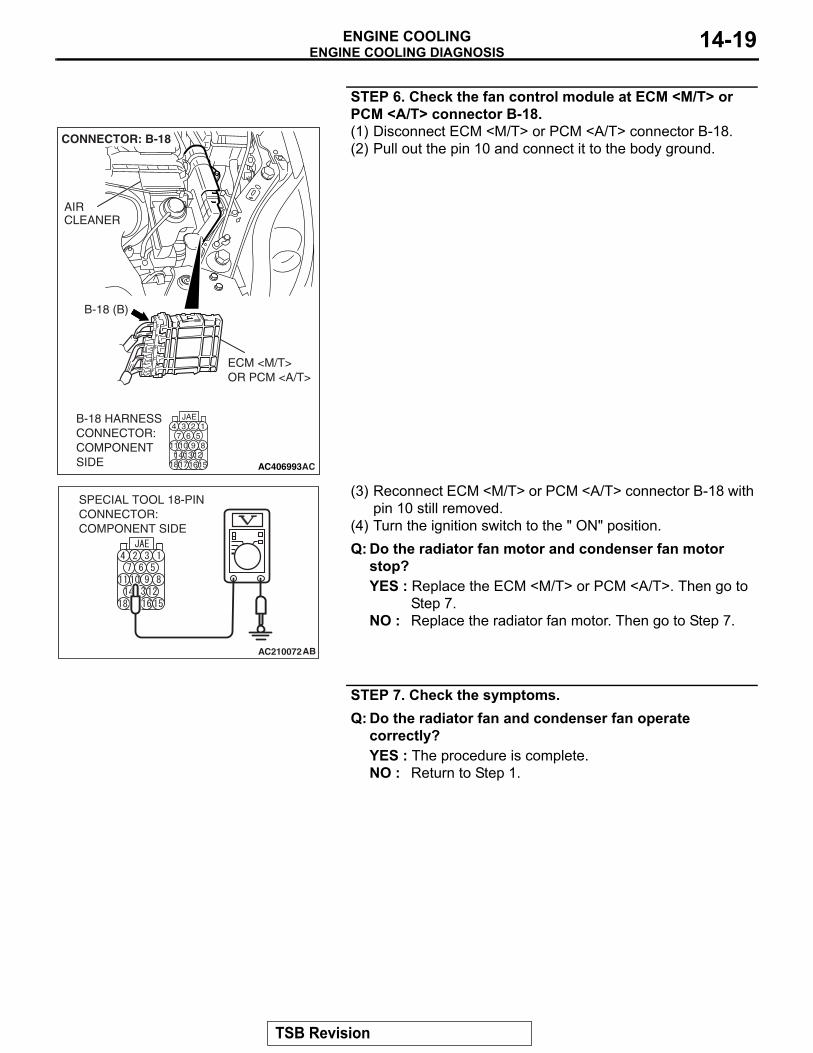
STEP 13. Check the fan control module at ECM <M/T> or PCM <A/T> connector B-18 (terminal 10).
AC406993AC
B-18 (B)
CONNECTOR: B-18
ECM <M/T> OR PCM <A/T>
AIRCLEANER
B-18 HARNESSCONNECTOR:COMPONENT SIDE
(1) Do not disconnect ECM <M/T> or PCM <A/T> connector B-18.
(2) Pull out terminal number 10.(3) Turn the ignition switch to the "ON" position.Q: Do the radiator fan motor and condenser fan motor
operate?YES : Replace the ECM <M/T> or PCM <A/T>. Then go to
Step 14.NO : Replace the radiator fan motor. Then go to Step 14.
STEP 14. Check the symptoms.Q: Do the radiator fan and condenser fan operate
correctly?YES : The procedure is complete.NO : Return to Step 1.
INSPECTION PROCEDURE 4: Radiator Fan and Condenser Fan do not Change Speed or Stop <3.8L Engine>
NOTE: If the engine coolant temperature reaches 110° C (230° F) or higher, the radiator fan control runs the radiator fan for up to 5 minutes even after the ignition switch is turned to the "LOCK" (OFF) position [the fan stops its rotation when the engine coolant temperature decreases to 110° C (230° F) or lower.].
Radiator Fan and Condenser Fan Drive Circuit Refer to P.14-7..
CIRCUIT OPERATION• The fan control module is powered from fusible
link number 2.
• The ECM <M/T> or PCM <A/T> judges the required revolution speed of radiator fan motor and condenser fan motor using the input signals transmitted from A/C switch, automatic compres-sor controller, vehicle speed sensor and engine coolant temperature sensor. The ECM <M/T> or PCM <A/T> activates the fan control module to drive the radiator fan motor and condenser fan motor.
.
TSB Revision
ENGINE COOLING DIAGNOSISENGINE COOLING 14-15
TECHNICAL DESCRIPTIONThe fan controller has variable control of the radiator fan motor and the condenser fan motor speeds using signals transmitted from the ECM <M/T> or PCM <A/T>.
.
TROUBLESHOOTING HINTS• Malfunction of fan control relay• Malfunction of fan control module• Malfunction of ECM <M/T> or PCM <A/T>
DIAGNOSISRequired Special Tools:• MB991223: Harness Set• MB991923: Power Plant ECU Check Harness
.
STEP 1. Check the fan control relay. Refer to P.14-24.Q: Is the fan control relay in good condition?
YES : Go to Step 2.NO : Replace the part, then go to Step 7.
STEP 2. Check the harness wire between fan control relay connector A-12X (terminal 2) and fan control module connector A-22 (terminal 3).
AC407060AJ
A-12X
CONNECTOR: A-12X
3
14 2
RELAY BOX SIDE
FRONT OF VEHICLE
AC204370
A-22
CONNECTOR: A-22
AJ
Q: Are the harness wires between fan control relay connector A-12X and fan control module connector A-22 damaged?YES : Repair or replace the part, then go to Step 7.NO : Go to Step 3.
TSB Revision
ENGINE COOLING DIAGNOSISENGINE COOLING14-16
STEP 3. Measure the output circuit voltage at ECM <M/T> or PCM <A/T> connector B-18 (terminal 10) by using check harness special tool MB991923.
AC406993AC
B-18 (B)
CONNECTOR: B-18
ECM <M/T> OR PCM <A/T>
AIRCLEANER
B-18 HARNESSCONNECTOR:COMPONENT SIDE
(1) Disconnect all the connectors from the ECM <M/T> or PCM <A/T>.
AC209793AS
ECM <M/T> OR PCM <A/T>
MB991923
BODY SIDEHARNESS
SPECIAL TOOL 18-PIN CONNECTOR(ECM <M/T> OR PCM <A/T> CONNECTOR B-18)
B-18 (GR)
(2) Connect special tool MB991923 (check harness) between the ECM <M/T> or PCM <A/T> and the body-side harness connector.
(3) Start the engine and run it at idle. [Engine coolant temperature: 80° C (176° F) or less]
TSB Revision
ENGINE COOLING DIAGNOSISENGINE COOLING 14-17
AC210072AB
SPECIAL TOOL 18-PINCONNECTOR:COMPONENT SIDE
(4) Measure the voltage between terminal number 10 and ground.
Q: Is the voltage 0 to 0.3 volt when the radiator fan is not operating?YES : Go to Step 7.NO : Go to Step 4.
STEP 4. Check fan control module connector A-22 and ECM <M/T> or PCM <A/T> connector B-18 for loose, corroded or damaged terminals, or terminals pushed back in the connector.
AC204370
A-22
CONNECTOR: A-22
AJ
AC406993AC
B-18 (B)
CONNECTOR: B-18
ECM <M/T> OR PCM <A/T>
AIRCLEANER
B-18 HARNESSCONNECTOR:COMPONENT SIDE
Q: Are the connectors in good condition?YES : Go to Step 5.NO : Repair or replace the damaged components. Refer to
GROUP 00E, Harness Connector Inspection P.00E-2.
TSB Revision
ENGINE COOLING DIAGNOSISENGINE COOLING14-18
STEP 5. Check the harness wire between ECM <M/T> or PCM <A/T> connector B-18 (terminal 10) and fan control module connector A-22 (terminal 2).
AC204370
A-22
CONNECTOR: A-22
AJ
AC406993AC
B-18 (B)
CONNECTOR: B-18
ECM <M/T> OR PCM <A/T>
AIRCLEANER
B-18 HARNESSCONNECTOR:COMPONENT SIDE
Q: Are the harness wires between ECM <M/T> or PCM <A/T> connector B-18 and fan control module connector A-22 damaged?YES : Repair or replace them, then go to Step 7.NO : Go to Step 6.
TSB Revision
ENGINE COOLING DIAGNOSISENGINE COOLING 14-19
STEP 6. Check the fan control module at ECM <M/T> or PCM <A/T> connector B-18.
AC406993AC
B-18 (B)
CONNECTOR: B-18
ECM <M/T> OR PCM <A/T>
AIRCLEANER
B-18 HARNESSCONNECTOR:COMPONENT SIDE
(1) Disconnect ECM <M/T> or PCM <A/T> connector B-18.(2) Pull out the pin 10 and connect it to the body ground.
AC210072AB
SPECIAL TOOL 18-PINCONNECTOR:COMPONENT SIDE
(3) Reconnect ECM <M/T> or PCM <A/T> connector B-18 with pin 10 still removed.
(4) Turn the ignition switch to the " ON" position.Q: Do the radiator fan motor and condenser fan motor
stop?YES : Replace the ECM <M/T> or PCM <A/T>. Then go to
Step 7.NO : Replace the radiator fan motor. Then go to Step 7.
STEP 7. Check the symptoms.Q: Do the radiator fan and condenser fan operate
correctly?YES : The procedure is complete.NO : Return to Step 1.
TSB Revision
ENGINE COOLING DIAGNOSISENGINE COOLING14-20
INSPECTION PROCEDURE 5: Radiator Fan does not Operate <3.8L Engine>
.
TECHNICAL DESCRIPTIONThe cause could be a malfunction of the radiator fan motor or an open circuit between the fan control module and the radiator fan motor.
.
TROUBLESHOOTING HINTMalfunction of radiator fan motor
DIAGNOSISReplace the radiator fan motor.
INSPECTION PROCEDURE 6: Condenser Fan does not Operate <3.8L Engine>
.
Radiator Fan and Condenser Fan Drive Circuit Refer to P.14-7..
CIRCUIT OPERATION• The fan control module is powered from fusible
link number 2.• The ECM <M/T> or PCM <A/T> judges the
required revolution speed of radiator fan motor and condenser fan motor using the input signals transmitted from A/C switch, automatic compres-sor controller, vehicle speed sensor and engine coolant temperature sensor. The ECM <M/T> or PCM <A/T> activates the fan control module to drive the radiator fan motor and condenser fan motor.
.
TECHNICAL DESCRIPTIONThe cause could be a malfunction of the condenser fan motor or fan control module..
TROUBLESHOOTING HINTS• Malfunction of condenser fan motor• Malfunction of fan control module
DIAGNOSIS
STEP 1. Check the condenser fan motor.Refer to GROUP 55A, Condenser and Condenser Fan Motor P.55A-212.Q: Is the condenser fan motor in good condition?
YES : Go to Step 2.NO : Replace the condenser fan motor, then go to Step 3.
STEP 2. Check the fan control module. Refer to P.14-25.Q: Is the fan control module in good condition?
YES : Go to Step 3.NO : Replace the radiator fan motor, then go to Step 3.
STEP 3. Check the symptoms.Q: Does the condenser fan operate correctly?
YES : The procedure is complete.NO : Return to Step 1.
TSB Revision
ON-VEHICLE SERVICEENGINE COOLING 14-21
ON-VEHICLE SERVICEENGINE COOLANT LEAK CHECK
M1141001000463
WARNINGWhen pressure testing the cooling system, slowly release cooling system pressure to avoid getting burned by hot coolant.
CAUTION• Be sure to completely clean away any moisture from
the places checked.• When the tester is taken out, be careful not to spill any
coolant.• Be careful when installing and removing the tester and
when testing not to deform the filler neck of the radia-tor.
ACX01844 AB
CAP ADAPTER
ADAPTER
1. Check that the coolant level is up to the filler neck. Install a radiator tester and apply 160 kPa (23 psi) pressure, and then check for leakage from the radiator hose or connections.
2. If there is leakage, repair or replace the appropriate part.
RADIATOR CAP PRESSURE CHECKM1141001300572
NOTE: Be sure that the cap is clean before testing. Rust or other foreign material on the cap seal will cause an improper reading.
ACX01845 AB
CAP ADAPTER
1. Use a cap adapter to attach the cap to the tester.2. Increase the pressure until the indicator of the gauge stops
3. Replace the radiator cap if the reading does not remain at or above the limit.
TSB Revision
ON-VEHICLE SERVICEENGINE COOLING14-22
ENGINE COOLANT REPLACEMENTM1141001200780
WARNINGWhen removing the radiator cap, use care to avoid contact with hot coolant or steam. Place a shop towel over the cap and turn the cap counterclockwise a lit-tle to let the pressure escape through the vinyl tube. After relieving the steam pressure, remove the cap by slowly turning it counterclockwise.1. Drain the water from the radiator, heater core and engine
after unplugging the radiator drain plug and removing the radiator cap.
AC304173AC
CYLINDER BLOCK DRAIN PLUG
INTAKE MANIFOLD
<2.4L ENGINE>
AC407102AB
<3.8L ENGINE: LEFT BANK>
CYLINDER BLOCKDRAIN PLUG
AC306132AB
<3.8L ENGINE: RIGHT BANK>
CYLINDER BLOCKDRAIN PLUG
2. Drain the water in the water jacket by unplugging the drain plug of the cylinder block.
3. Remove the radiator condenser tank assembly and drain the coolant.
4. Drain the coolant then clean the path of the coolant by injecting water into the radiator from the radiator cap area.
TSB Revision
ON-VEHICLE SERVICEENGINE COOLING 14-23
AC304677AC
CYLINDER BLOCKDRAIN PLUG
<2.4L ENGINE, 3.8L ENGINE: RIGHT BANK>
AC200625AD
CYLINDER BLOCKDRAIN PLUG
<3.8L ENGINE: LEFT BANK>
5. Apply the designated sealant to the screw area of the cylinder block drain plug, and then tighten to the standard torque.
Specified sealant: 3M™ AAD Part No.8731 or equiva-lentTightening torque:
6. Securely tighten the radiator drain plug.7. Assemble the radiator condenser tank assembly.
CAUTIONDo not use alcohol or methanol anti-freeze or any engine coolants mixed with alcohol or methanol anti-freeze. The use of an improper anti-freeze can cause corrosion of the aluminum components.
AC406641
MB991871
AIR HOSE
<2.4L ENGINE>
AB
AC406265
MB991871
AIR HOSE
<3.8L ENGINE>
AB
8. By referring to the section on coolant, select an appropriate concentration for safe operating temperature within the range of 30 to 60%. Use special tool MB991871 to refill the coolant. A convenient mixture is a 50% water and 50% antifreeze solution [freezing point: − 31° C (− 32.8 ° F)].
Recommended antifreeze: Long Life Antifreeze Coolant or an equivalent
NOTE: For how to use special tool MB991871, refer to its manufacturer’s instructions.
9. Reinstall the radiator cap.10.Start the engine and let it warm up until the thermostat
opens.11.After repeatedly revving the engine up to 3,000 r/min several
times, stop the engine.12.Remove the radiator cap after the engine has cooled, and
pour in coolant up to the brim. Reinstall the cap.CAUTION
Do not overfill the radiator condenser tank assembly.13.Add coolant to the radiator condenser tank assembly
between the "FULL" and "LOW" mark if necessary.
TSB Revision
ON-VEHICLE SERVICEENGINE COOLING14-24
ENGINE COOLANT CONCENTRATION TESTM1141001100556
Refer to GROUP 00, RECOMMENDED LUBRICANTS AND LUBRICANT CAPACITIES TABLE P.00-42.
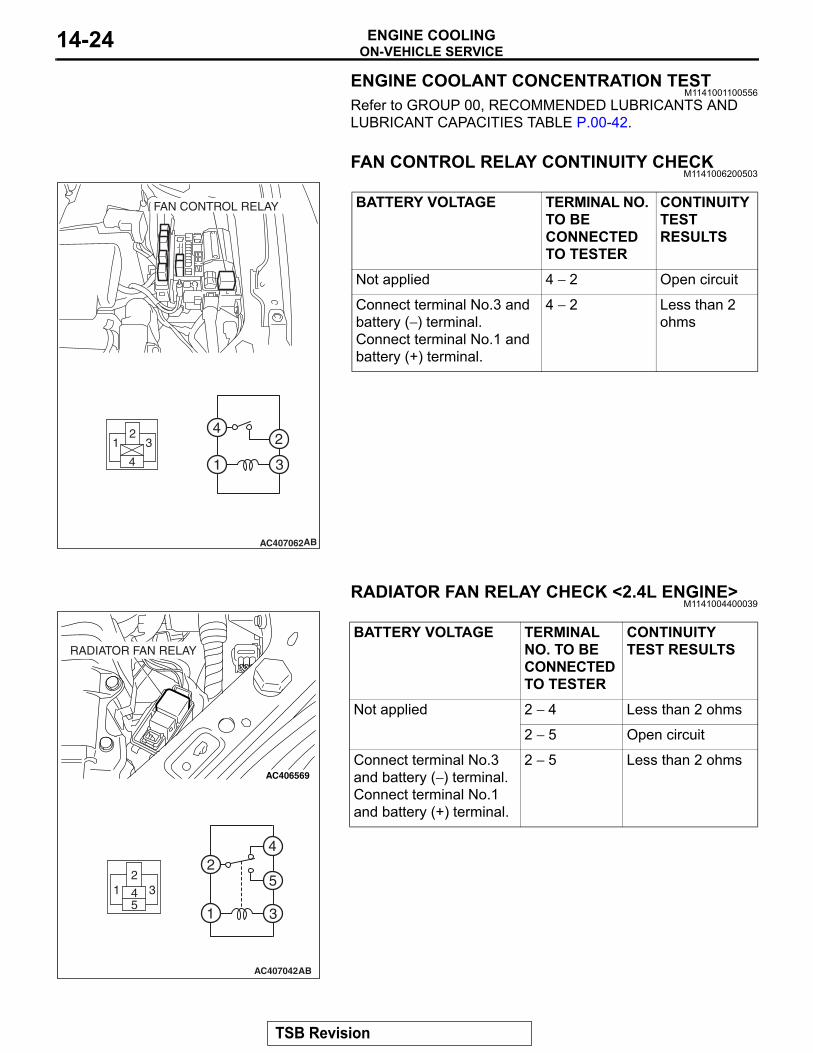
FAN CONTROL RELAY CONTINUITY CHECKM1141006200503
AC407062
FAN CONTROL RELAY
AB
3
4
1
2
BATTERY VOLTAGE TERMINAL NO. TO BE CONNECTED TO TESTER
CONTINUITY TEST RESULTS
Not applied 4 − 2 Open circuit
Connect terminal No.3 and battery (− ) terminal.Connect terminal No.1 and battery (+) terminal.
4 − 2 Less than 2 ohms
RADIATOR FAN RELAY CHECK <2.4L ENGINE>M1141004400039
AC407042
AC406569
RADIATOR FAN RELAY
AB
BATTERY VOLTAGE TERMINAL NO. TO BE CONNECTED TO TESTER
CONTINUITY TEST RESULTS
Not applied 2 − 4 Less than 2 ohms
2 − 5 Open circuit
Connect terminal No.3 and battery (− ) terminal.Connect terminal No.1 and battery (+) terminal.
2 − 5 Less than 2 ohms
TSB Revision
ON-VEHICLE SERVICEENGINE COOLING 14-25
FAN CONTROL MODULE CHECK <3.8L ENGINE>M1141007400135
AC204370
FAN CONTROL MODULE
AD
23 1
1. Remove the fan control module connector.2. Turn the ignition switch to the "ON" position, and measure
the voltage between the harness-side connector terminals.Standard value: Battery positive voltage
AC204370
FAN CONTROL MODULE
AF
1 2
CONDENSER FANMOTOR CONNECTOR
3. Connect the fan control module connector, and disconnect the condenser fan motor connector.
4. Ensure that the A/C switch is off, and start the engine and run it at idle.
5. Measure the voltage between the fan control module-side connector terminals.
Standard value: 1 volt or less
WARNING Stay clear of the fan when the fan starts running.6. Turn the A/C switch to the "ON" position.7. Measure the voltage between the fan control module-side
connector terminals while the fan is running. The voltage should repeat the values 1) and 2) below.
Standard value:1) 8.2 ± 2.6 volts2) Battery positive voltage ± 2.6 volts
8. If the voltage does not repeatedly change as indicated, replace the radiator fan motor.
COOLING FAN MOTOR CHECK <2.4L ENGINE>M1141007600010
AC306130
COOLING FUN MOTOR (LH)
1 2
AC
1. Remove the cooling fan motor connector.2. Check to see that the fan motor of the radiator turns when
applying battery power between the connector terminals of the radiator fan motor. Also check to see that there is no abnormal sound coming from the cooling fan motor at this time.
3. If the cooling fan motor is defective, replace it. (Refer to P.14-26.)
TSB Revision
RADIATORENGINE COOLING14-26
RADIATORREMOVAL AND INSTALLATION
M1141001500941
<2.4L ENGINE>Pre-removal Operation• Engine Coolant Draining (Refer to P.14-22).• Air Cleaner Removal (Refer to GROUP 15, Air Cleaner
P.15-4).
Post-installation Operation• Air Cleaner Installation (Refer to GROUP 15, Air Cleaner
P.15-4).• Engine Coolant Refilling and Level Check (Refer to
P.14-22).• Transmission Fluid Refilling and Level Check (Refer to
GROUP 42, HOOD P.42-7).6. FRONT END STRUCTURE BAR7. UPPER INSULATOR8. CONDENSER BOLTS9. RADIATOR ASSEMBLY10. LOWER INSULATOR11. RADIATOR CONDENSER TANK
ASSEMBLY<<B>> 12. TRANSMISSION FLUID COOLER
LINE HOSE13. CONDENSER FAN MOTOR
CONNECTOR14. CONDENSER FAN SHROUD
ASSEMBLY15. COOLING FAN SHROUD
ASSEMBLY16. RADIATOR
FAN MOTOR REMOVAL STEPS 1. RADIATOR CONDENSER TANK
HOSE5. FAN CONTROL MODULE
CONNECTOR<<A>> >>A<< 3. RADIATOR UPPER HOSE
13. CONDENSER FAN MOTOR CONNECTOR
11. RADIATOR CONDENSER TANK ASSEMBLY
14. CONDENSER FAN SHROUD ASSEMBLY
15. COOLING FAN SHROUD ASSEMBLY
17. CONDENSER FAN18. HEAT PROTECTOR19. CONDENSER FAN MOTOR20. COOLING FAN21. COOLING FAN MOTOR
Make mating marks on the radiator hose and the hose clamp. Disconnect the radiator hose.
.
<<B>> TRANSMISSION FLUID COOLER LINE HOSE REMOVALAfter removing the hose from the radiator, plug the hose and the radiator nipple to prevent dust or foreign particles from get-ting in.
1. Insert each hose as far as the projection of the water inlet fitting.
2. Align the mating marks on the radiator hose and hose clamp, and then connect the radiator hose.
THERMOSTATREMOVAL AND INSTALLATION <2.4L ENGINE>
M1141002400754
Pre-removal and Post-installation Operation• Engine Coolant Draining and Refilling (Refer to P.14-22).• ECM <M/T> or PCM <A/T> Removal and Installation
(Refer to GROUP 13A, Engieine Control Module (ECM) and Powertrain Control Module (PCM) P.13A-1214).
• Air Cleaner Housing Cover and Air Intake Hose Removal and Installation (Refer to GROUP 15, Air Cleaner P.15-4).
• Battery and Battery Tray Removal and Installation.
Make mating marks on the radiator hose and the hose clamp. Disconnect the radiator hose.
INSTALLATION SERVICE POINTS.
>>A<< THERMOSTAT INSTALLATIONCAUTION
Make absolutely sure that no oil adheres to the rubber ring of the thermostat. Also do not fold or scratch the rubber ring during installation.
AC000279
JIGGLE VALVE
RUBBER RING
AB
Install the thermostat so that the jiggle valve is facing straight up. Be careful not to fold or scratch the rubber ring.
.
>>B<< RADIATOR LOWER HOSE CONNECTION
AC200642
MATINGMARKS
PROJECTION
WATER INLET FITTING
AE
1. Insert each hose as far as the projection of the water inlet fitting.
2. Align the mating marks on the radiator hose and hose clamp, and then connect the radiator hose.
TSB Revision
THERMOSTATENGINE COOLING 14-31
REMOVAL AND INSTALLATION <3.8L ENGINE>M1141002400776
Pre-removal and Post-installation Operation• Engine Coolant Draining and Refilling (Refer to P.14-22).• Engine Cover Removal and Installation (Refer to GROUP
11C, Engine Assembly P.11C-22).• ECM <M/T> or PCM <A/T> Removal and Installation
(Refer to GROUP 13B, Engine Control Module (ECM) and Powertrain Control Module (PCM) P.13B-1295).
• Air Cleaner Removal and Installation (Refer to GROUP 15, Air Cleaner P.15-5).
• Strut Tower Bar Removal and Installation (Refer to GROUP 42, Strut Tower Bar P.42-12).
• Battery and Battery Tray Removal and Installation
AC406185
2
1
3
4
1
19 ± 1 N·m14 ± 1 ft-lb
5.0 ± 1.0 N·m44 ± 9 in-lb
5.0 ± 1.0 N·m44 ± 9 in-lb
AB
REMOVAL STEPS 1. HARNESS CONNECTION BOLTS
<<A>> >>B<< 2. RADIATOR LOWER HOSE CONNECTION
3. WATER INLET FITTING>>A<< 4. THERMOSTAT
REMOVAL STEPS (Continued)
TSB Revision
THERMOSTATENGINE COOLING14-32
REMOVAL SERVICE POINT.
<<A>> RADIATOR LOWER HOSE DISCONNEC-TION
AC200641AB
MATING MARKS
Make mating marks on the radiator hose and the hose clamp. Disconnect the radiator hose.
INSTALLATION SERVICE POINTS.
>>A<< THERMOSTAT INSTALLATIONCAUTION
Make absolutely sure that no oil adheres to the rubber ring of the thermostat. Also do not fold or scratch the rubber ring during installation.
AC000279
JIGGLE VALVE
RUBBER RING
AB
Install the thermostat so that the jiggle valve is facing straight up. Be careful not to fold or scratch the rubber ring.
.
>>B<< RADIATOR LOWER HOSE CONNECTION
AC200642
MATINGMARKS
PROJECTION
WATER INLET FITTING
AE
1. Insert each hose as far as the projection of the water inlet fitting.
2. Align the mating marks on the radiator hose and hose clamp, and then connect the radiator hose.
TSB Revision
THERMOSTATENGINE COOLING 14-33
INSPECTIONM1141002500609
.
Thermostat Check
ACX00400
1. Immerse the thermostat in water, and heat the water while stirring. Check the thermostat valve opening temperature.
Standard value:Valve opening temperature: 82 ± 1.5° C (180 ± 3° F)
ACX00401AB
VALVE LIFT
2. Check that the amount of valve lift is at the standard value when the water is at the full-opening temperature.NOTE: Measure the valve height when the thermostat is fully closed, and use this measurement to compare the valve height when the thermostat is fully open.
Standard value:Full-opening temperature: 95° C (203° F)Amount of valve lift:
<2.4L Engine> 8.5 mm (0.33 inch) or more<3.8L Engine> 9.0 mm (0.35 inch) or more
TSB Revision
WATER PUMPENGINE COOLING14-34
WATER PUMPREMOVAL AND INSTALLATION <2.4L ENGINE>
M1141002700863
Pre-removal and Post-installation Operation• Engine Coolant Draining and Refilling (Refer to P.14-22).• Timing Belt Removal and Installation (Refer to GROUP
11A, Timing Belt P.11A-50).
AC406780AC
12
3
N
N
14 ± 1 N·m120 ± 13 in-lb
14 ± 1 N·m120 ± 13 in-lb
BOLT SPECIFICATIONS
THREAD DIAMETER × LENGTH mm (in)
8 × 55(0.3 × 2.2)
8 × 55(0.3 × 2.2)
8 × 22(0.3 × 0.9)
8 × 22(0.3 × 0.9)
8 × 14(0.3 × 0.6)
REMOVAL STEPS 1. WATER PUMP 2. WATER PUMP GASKET
>>A<< 3. O-RING
INSTALLATION SERVICE POINT.
>>A<< O-RING INSTALLATIONCAUTION
Do not let the O-ring get contaminated with grease or engine oil.
AC103005
WATER PUMP
O-RING
WATER INLET PIPE
AC
Fit an O-ring into the O-ring groove located at the end of the water inlet pipe and apply water or coolant to the O-ring or the inside of the mounting surface of the water pump for insertion.
REMOVAL STEPS (Continued)
TSB Revision
WATER PUMPENGINE COOLING 14-35
REMOVAL AND INSTALLATION <3.8L ENGINE>M1141002700885
Pre-removal and Post-installation Operation• Engine Coolant Draining and Refilling (Refer to P.14-22).• Timing Belt Removal and Installation (Refer to GROUP
11C, Timing Belt P.11C-59).• Crankshaft Position Sensor Removal and Installation
(Refer to GROUP 16, Crankshaft Position Sensor P.16-45).
AC406186
24 ± 3 N·m18 ± 2 ft-lb
42 ± 8 N·m31 ± 6 ft-lb
24 ± 3 N·m18 ± 2 ft-lb
1
2
3
4N
N
AB
BOLT SPECIFICATIONS
THREAD DIAMETER × LENGTH mm (in)
10 × 38(0.4 × 1.5)
8 × 25(0.3 × 1.0)
8 × 25(0.3 × 1.0)
8 × 20(0.3 × 0.8)
REMOVAL STEPS 1. WATER PUMP BRACKET2. WATER PUMP
3. WATER PUMP GASKET>>A<< 4. O-RING
INSTALLATION SERVICE POINT.
>>A<< O-RING INSTALLATIONCAUTION
Do not let the O-ring get contaminated with grease or engine oil.
AC200644 AB
O-RING
WATER PIPE
Fit the O-ring into the groove of the water pipe ends, and apply water or coolant to the circumference of the O-ring and the pipe bores to insert the pipe assembly.
REMOVAL STEPS (Continued)
TSB Revision
WATER HOSE AND WATER PIPEENGINE COOLING14-36
WATER HOSE AND WATER PIPEREMOVAL AND INSTALLATION <2.4L ENGINE>
M1141003300910
Pre-removal and Post-installation Operation• Engine Coolant Draining and Refilling (Refer to P.14-22).• ECM <M/T> or PCM <A/T> Removal and Installation
(Refer to GROUP 13A, Engine Control Module (ECM) and Powertrain Control Module (PCM) P.13A-1214).
• Air Cleaner Removal and Installation (Refer to GROUP 15, Air Cleaner P.15-4).
• Thermostat Removal and Installation (Refer to P.14-29).
AC406393AC406393
9
12
6
13 N
11
11 ± 1 N·m98 ± 8 in-lb
13 ± 2 N·m111 ± 22 in-lb
AB
10
1
3
4
5
2
87
13 ± 2 N·m111 ± 22 in-lb
13 N
24 ± 4 N·m18 ± 3 ft-lb
REMOVAL STEPS <<A>> >>C<< 1. RADIATOR UPPER HOSE
CONNECTION2. RADIATOR LOWER HOSE
CLAMP3. WATER HOSE CLAMP4. WATER COOLER HOSE
CONNECTION>>B<< 5. WATER OUTLET FITTING
6. HEATER WATER HOSE CONNECTION
7. WATER HOSE>>B<< 8. THERMOSTAT CASE
9. HEATER WATER HOSE CONNECTION
10. WATER COOLER HOSE CONNECTION
11. WATER HOSE12. WATER INLET PIPE
>>A<< 13. O-RINGS
REMOVAL STEPS (Continued)
TSB Revision
WATER HOSE AND WATER PIPEENGINE COOLING 14-37
REMOVAL SERVICE POINT.
<<A>> RADIATOR UPPER HOSE DISCONNEC-TION
AC200641AB
MATING MARKS
After making mating marks on the radiator hose and hose clamp, disconnect the radiator hose.
INSTALLATION SERVICE POINTS.
>>A<< O-RINGS INSTALLATIONCAUTION
Do not let the O-ring get contaminated with grease or engine oil.
AC200644AC
O-RING
WATER INLET PIPE
WATER PUMP OR THERMOSTAT CASEFit an O-ring into the groove of the water inlet pipe and apply water or coolant to the circumference of the O-ring or the inside of the mounting surface of the water pump or thermostat case for insertion.
.
>>B<< THERMOSTAT CASE/WATER OUTLET FITTING INSTALLATION1. Use a gasket scraper or wire brush to completely eliminate
all gasket material on the gasket mounting surface.
AC305204AE
φ 3 mm(0.12 in)
THERMOSTAT CASEWATER OUTLETFITTING
2. Apply a bead of the sealant to the cylinder head mating surface of the thermostat case as shown.
Specified Sealant: 3M™ AAD Part No.8672, 3M™ AAD Part No.8679/8678 or equivalent
TSB Revision
WATER HOSE AND WATER PIPEENGINE COOLING14-38
AC303724AD
THERMOSTAT CASE 3. Apply sealant to the thread of the thermostat case bolts as shown.
Specified Sealant: 3M™ AAD Part No.8730, 8731 or equivalent
4. With the sealant still wet (within 15 minutes after the sealant is applied), install the thermostat case. Do not apply the sealant in an area more than the required.
.
>>C<< RADIATOR UPPER HOSE CONNECTION
AC200642
MATINGMARKS
PROJECTION
WATER OUTLETFITTING
AB
1. Insert each hose as far as the projection of the water outlet fitting.
2. Align the mating marks on the radiator hose and hose clamp, and then connect the radiator hose.
TSB Revision
WATER HOSE AND WATER PIPEENGINE COOLING 14-39
REMOVAL AND INSTALLATION <3.8L ENGINE>M1141003300943
Pre-removal and Post-installation OperationThermostat Removal and Installation (Refer to P.14-31).
After making mating marks on the radiator hose and hose clamp, disconnect the radiator hose.
INSTALLATION SERVICE POINTS.
>>A<< O-RING INSTALLATION
AC200644 AB
O-RING
WATER PIPE
CAUTIONDo not allow engine oil or other grease to adhere to the O-ringInsert the O-ring to the water pipe, and coat the outer portion of the O-ring with water or engine coolant.
.
>>B<< ENGINE COOLANT TEMPERATURE SENSOR INSTALLATION
AC208408AB
Apply the specified sealant to the thread of the engine coolant temperature sensor, and then tighten it to the specified torque.
Specified Sealant: 3M™ AAD Part No. 8731 or equiva-lent
.
TSB Revision
WATER HOSE AND WATER PIPEENGINE COOLING 14-41
>>C<< RADIATOR UPPER HOSE CONNECTION
AC200642
MATINGMARKS
PROJECTION
WATER OUTLETFITTING
AB
1. Insert each hose as far as the projection of the water outlet fitting.
2. Align the mating marks on the radiator hose and hose clamp, and then connect the radiator hose.
INSPECTIONM1141003400434
.
Water Pipe and Hose CheckCheck the water pipe and hose for cracks, damage and clogs. Replace them if necessary.
• When the A/C switch is off.• Measure the fan control
module-side connector.
1 or less −
• When the A/C switch is "ON" position.
• Measure the fan control module-side connector.
Repeat 8.2 ± 2.6 and Battery positive voltage ± 2.6
−
Fan control module connector voltage V
• When the ignition switch is "ON" position.
• Measure the harness-side connector.
Battery positive voltage
−
High-pressure valve opening pressure of radiator cap kPa (psi) 93 − 123 (14 − 18) Minimum 83 (12)Thermostat Valve opening temperature of thermostat ° C (° F) 82 ± 1.5 (180 ± 3) −
Full-opening temperature of thermostat ° C (° F) 95 (203) −Valve lift mm (in) 2.4L Engine 8.5 (0.33) or more −
3.8L Engine 9.0 (0.35) or more −
CAPACITIESM1141005100150
ITEM QUANTITY dm3 (qt)Long life antifreeze coolant or an equivalent 2.4L Engine M/T 8.8 (9.3)
A/T 8.7 (9.2)3.8L Engine M/T 8.1 (8.6)
A/T 8.0 (8.5)
SEALANTSM1141000500584
<2.4L ENGINE>ITEM SPECIFIED SEALANTCylinder block drain plug 3M™ AAD Part No.8731 or equivalentThermostat case 3M™ AAD Part No.8672, 3M™ AAD Part No.8679/8678 or
equivalentWater outlet fittingThermostat case bolt 3M™ AAD Part No. 8730, 8731 or equivalent
<3.8L ENGINE>ITEM SPECIFIED SEALANTCylinder block drain plug 3M™ AAD Part No.8731 or equivalentEngine coolant temperature sensor