MTR JULKAISUT, N:RO 1 Raportti Elokuu 2003 MAANALAISTEN TILOJEN RAKENTAMISYHDISTYS RY FINNISH TUNNELLING ASSOCIATION MTR ry Kalliorakentamisen kilpailukyky - kehitysohjelma Pasi Tolppanen & Pauli SyrjänenGridpoint Finland OyINTE Hard Rock Tunnel Grouting Practice in Finland, Sweden, and Norway - Literature Study
AbstractGrouting has developed greatly in the last decade. Improvements of grout material andequipment enable better quality final products. Grouting has become an important andmeaningful part of underground construction. The environmental requirements havealso tightened more in recent years and the harmful lowering of the groundwater level isforbidden.
Cementitious materials are mostly used in rock grouting in tunnels. Furthermore, due tothe high level of the tightness requirements, very fine-grained cements are more often
used since very small fracture apertures must be grouted. Many different chemicalgrouts also exist on the market, but after some environmental accidents their use has been limited or even forbidden. Chemical grouts are mainly used in very difficult placesfor post grouting.
A great deal of effort has gone into grouting design and compliance control. It is notenough to just evaluate or measure the leakages of the final tunnel. The deviation andleakage of grouting holes are measured and control holes are drilled into the groutedsection. Moreover, the limitations and requirements for grouts are defined andinspected - even at the site. While designing, the varying geological features are takeninto account and tunnels are divided into sections of different grouting classes.
Experiences and opinions on grouting in Finland, Norway, and Sweden have beencollected and published in this report. The material presented is based on the literature,interviews, site visits, and the authors' own experiences. Furthermore, the discussions atthe follow-up group meetings are also important.
Injektoinnissa on tapahtunut runsaasti kehitystä viimevuosina. Materiaalien jalaitteistojen paraneminen on luonut mahdollisuuden yhä laadukkaammillelopputuotteille. Injektointi on kytketty keskeiseksi osaksi kalliorakentamista. Myösympäristötekijät ovat korostuneet viime vuosina ja pohjaveden haitallista alenemista eisallita.
Sementtipohjaiset massat ovat selkeästi eniten käytetty kalliorakentamisessa. Viimevuosina on yhä enemmän siirrytty erittäin hienojakoisten sementtien käyttöön sillätunneleiden vuotovesimäärien kiristyneet vaatimukset on johtanut tarpeeseen tiivistääyhä hienompia rakoja. Myös kemiallisia injektointiaineita on markkinoilla runsaasti,mutta muutamien ympäristökatastrofien tapahduttua on niiden käyttöä rajoitettu.Kemiallisia aineita on käytetty lähinnä hankalissa kohteissa jälki-injektoinnissa.
Kiristyneet tiiveysvaatimukset ja etenkin mikro- ja ultrahienojen sementtien lisääntyväkäyttö on ohjannut myös laitteiden kehitystä. Keskeistä on ollut sekoittimien ja
pumppujen kehittyminen sekä laitteistojen muokkautuminen ”järjestelmiksi”. Myösautomaattisten rekisteröintilaitteiden liittäminen osaksi järjestelmää on auttanutlaadukkaan lopputuotteen aikaansaamista.
Myös suunnitteluun ja laadunvarmistukseen on viime vuosina keskitytty enemmän.Pelkkä lopputuotteen vuotomäärien toteaminen ei riitä vaan injektointireikien taipumia
ja vesimenekkejä mitataan sekä porataan kontrollireikiä injektoituun osuuteen. Myösinjektointimassoille on esitetty omia laatuvaatimuksia, joita tarkkaillaan myöstyömaalla. Suunnittelussa pyritään ottamaan alueelliset geologiset vaihtelut huomioon
jakaen tunneli vaatimustasoltaan erilaisiin osioihin.
Tässä raportissa on kerätty kokemuksia ja näkemyksiä injektoinnista Suomessa,Ruotsissa ja Norjassa. Esitetty aineisto pohjautuu kirjallisuuteen ja haastatteluihin sekäkenttäkäynteihin ja kirjoittajien omiin kokemuksiin. Runsaasti tietoa ja kokemuksia onkuultu myös projektin seurantaryhmän palavereissa.
This report is a “first phase” study for the Finnish Grouting Instructions (INTE) project.INTE is part of the “Competitive Rock Building” development program organized by
the Finnish Tunnelling Association – FTA (MTR ry). Financial support for the projectfrom Helsinki City Real Estate Department Geotechnical Division, Finnish RailAdministration, Finnish Road Administration, ELKEM ASA Materials, Master BuildersOy, Lemcon Oy, YIT Construction Oy, ITS-Vahvistus Oy, and Oy Atlas Copco Ab isgratefully acknowledged. The exchange of information and co-operation with PosivaOy is also appreciated.
The project follow-up group was:
Raimo Viitala, Ilkka Satola / Helsinki City, Real Estate Department, GeotechnicalDivision
Harri Yli-Villamo / Finnish Rail Administration
Timo Cronvall / Oy VR-Rata Oy
Olli Niskanen / Finnish Road Administration
Steinar Roald, Olav Guldseth, Tor-Søyland Hansen / ELKEM ASA, Materials
Ari Laitinen/ Master Builders Oy,
Hans-Olav Hognestad, Ola Woldmo / Degussa Ab
Bjarne Liljestrand / Lemcon Oy
Tuomo Tahvanainen / YIT Construction Oy
Arto Niemeläinen / ITS-Vahvistus Oy
Ilkka Eskola, Sten-Åke Pettersson, Heikki Räsänen / Oy Atlas Copco Ab
Reijo Riekkola / Saanio & Riekkola Oy
Tapani Lyytinen / Posiva Oy
Erkki Holopainen / Finnish Tunnelling Association
Pekka Salmenhaara / DeNeef Finland Oy
Esko Aaltonen / Muottikolmio Oy
Pauli Syrjänen, Pasi Tolppanen / Gridpoint Finland Oy
Furthermore, the authors would like to thank Ursula Sievänen / Saanio & Riekkola Oy,Vesa Vaaranta and Kari Korhonen / Lemcon Oy, Morten Rongmo / MIKA Contractor AS, Reidar Løvhaugen / Statens Vegvesen Tarald Nomeland / Elkem Materials ASAand Jukka Pöllä / Fundus Oy (on behalf of Finnish Tunneling Association) for their time, fruitful discussions and comments.
3.3 Chemical grouts.....................................................................................................................26 3.3.1 Testing methods for chemical grouts..................................................................................29
The aim of this literature report was to collect information about the hard rock groutingexperiences and present status in Nordic countries, mainly in Finland, Sweden and
Norway.
For this study, the recent research work by several institutes like Royal Institute of Technology in Stockholm, Norwegian University of Science and Technology inTrondheim and Helsinki University of Technology have been checked and referred to.Also, the experiences of client representatives, construction companies, as well asmaterial and equipment producers, have been collected by site visits and personaldiscussions. In addition, there was an exchange of information with Posiva Oy (Nuclear waste management in Finland). The Finnish and Swedish grouting experiences are
partly based on reports by Posiva Oy.
In Sweden and Norway, a great deal of effort has been focused on grouting research and practice. Also, the well-known unsuccessful projects in Sweden and Norway haveincreased the interest in grouting. So, it can be noted that the level of groutingknowledge and understanding in Finland should be increased, partly by utilizing theexperiences of neighboring countries.
The current grouting material and equipment are high tech instruments and very suitablefor the aggressive fight against leaking water to ensure dry tunnels and a stableenvironment. Also, the geological tools from site mapping to fancy computer-basedmodels provide a very useful information base for evaluating leakage and for grouting
procedure design.
This report will also be a basis for the Finnish Grouting Instructions that will be published in 2004.
Several analytical and empirical equations for water leakage evaluation at various
purposes and depths have been presented. Cesano (1999, 2001) and Dalmalm (2001) present wide summaries of leakage evaluation methods in their thesis. Also, Sievänen(2001) evaluates different analytical methods in her licentiate thesis. She stated that anequation, which is based on the imaginary well approach, is the most reliable when thedepth of the tunnel is about three times the level of the water table. The equation isdiscussed in more detail in Appendix A and used in the following examples. Thiem’swell equation is suitable for more shallow excavations (Airaksinen, 1978).
Water inflow into the cavern or tunnel is highly dependent on the hydraulic conductivityof the rock mass (Fig. 2.1); both for ungrouted and grouted zones. Also, the depth of thetunnel level, that is the water pressure, has an effect. This is, however, a more
complicated factor to take into account since hydraulic conductivity is known todecrease by depth as can be seen in the Olkiluoto site (Äikäs et al ., 2000). The tunnelradius is less important (Fig. 2.2).
The rule of thumb is that the effect of joint opening on hydraulic conductivity followsthe cubic theory. Thus, an opening two units wider presents an inflow 8 times higher.However, this is only valid when the fracture is consistent and channeled successfully toan unlimited aquifer by unlimited openings. Furthermore, factors like joint roughness,
percentage of contact areas, infillings, etc. decrease the flow capacity. So, for eachfracture flow the properties are much affected by boundary conditions – not just the
parameters of the fracture itself. This has been studied very much (for example by
Hakami, 1995; Lanaro, 2001; Fardin, 2001; Zimmerman et al ., 1991) for numerousapplications and is still not completely solved as stated by Eriksson (2002).
Environmental requirements have been tightened in last few years – especially in cityareas. In most cases, it has been stated that excavation of underground tunnels or
caverns should not lower groundwater table if it causes significant:
• consolidation / subsidence of ground (especially in building areas),
• rotting of wooden piles under buildings,
• drying of wells, or,
• drying of vegetation if it should be preserved.
Based on the Swedish experiences, even an inflow amount of 5 - 10 l/min/100 m can be
enough to cause a permanent decrease in the water table level (Hartikainen, 1973). Insome cases in the Oslo area, an inflow of 1 - 2 l/min/100 m has been found to be toomuch for the groundwater table, Roald (2002). It is difficult to specify any exact values,since the influence can vary considerably from place to place due to the size of the localaquifer and water recharge.
2.3 Requirements due to the cavern use
The use of the excavated facility also sets requirements for water sealing. The strictest
requirements for underground constructions, 0.5 - 5 l/min/100 m, are set for road andrailway tunnels, and, for some special caverns like telecommunication shelters. In thecase of low requirement caverns like water tunnels, the level of 40 - 80 l/min/100 m istypically used. However, these limits are also dependent on the other requirements suchas environment.
2.4 Strengthening of rock by grouting
Barton et al. (2001) have presented an idea for strengthening rock by grouting. Theyhave found that grouting affects the quality of weaker rock more than the better quality
of rock. In very weak rock (Q < 0.3) the grouting effect is highest, even two to threeQ-classes, but with the good and very good rock (Q > 10) the difference is very limited.
2.5 Experienced gained from constructed tunnels
Based on the Nordic experiences, the target of a few l/min/100 m tunnel can realistically be reached by conventional grouting technique in "a normal geological environment".Also, the environmental effects due to the water inflow were eliminated quite well bygrouting (see Appendix B). It has been noted that the inflow of groundwater can be as
low as 1 l/min/100 m tunnel after grouting for a large cement grouted tunnel (100 m2
and excavated some 10 - 50 m below water table (for example, Bäckblom, 2002; Roald,2002; Statens Vegvesen, 2001; Stille, 2001). Though, some unlucky experiences alsoexist. For example, in the case of the Turku-Naantali water tunnel pre-grouting wasdestroyed by not waiting long enough and the inflow waters were moved to nearby
fractures after post-grouting (Sievänen & Hagros, 2002). Similar phenomenon happenedin Norway in the Tåsen tunnel where several reasons led to an unsatisfactory sealingresult (Statens Vegvesen, 2001). In many cases, one or two major fractures or crushzones control most of the inflow amounts - even after a trial grouting; for example, atOlkiluoto & Loviisa VLJ repositories (Sievänen & Hagros, 2002). Furthermore, weshould also not forget the environmental and economic catastrophes at Hallandsåsenand Romeriksporten.
In some cases from Finland, Sweden, and Canada the seepage decrease in time might be0.3 - 1.1 % / month (Bäckblom, 2002). The reasons for this are not understood, but oneexplanation is that it is due to precipitation of calcite and/or bacteria, degassing, and
rock creep, etc. But as at URL, there might be a remarkable decrease after excavationwork (30 m3/day => 20 m3/day in the first two years), but leveling out during that time -at URL the current leakage has settled at 10 m3/day.
Several opinions concerning the limit of achievable hydraulic conductivity exist:
• The achieved maximum tightness varies between 1*10-7 m/s - 2.5*10-9 m/s,depending on the materials used and the geology around the tunnel (Bäckblom,2002).
• Experiences in Oslo show that it is difficult to grout if the hydraulic conductivity
is lower than 2.5*10-9
m/s (comment found in Hallandsås documentation,Bäckblom, 2002).
• Using ordinary cement, a final result of K = 3*10-7 m/s is a practical limit (Stille,2001).
• The channels with an aperture smaller than 30 µm (equal to K = 10-9 m/s) can beassumed to be wholly or partially unfilled by grouting, even with dynamicgrouting with very fine cement (max grain size 15 µm) – conclusion in theStripa project (Pusch et al ., 1985).
• Generally accepted “rules-of-thumb” say; apertures >0.1 mm are groutable withmicrocements and the aperture/cement grain size ratio should be > 3 (for example, Roald, 2002).
• It was found in the Hallandsås project that the mean flow reduction-% variesfrom 21 - 81 % for cements and 95 - 98 % for chemical grouts (2 differentrecipes), and 15 - 93 % for a mix of cement and chemical grouts (3 recipes)(Bäckblom, 2002).
3.1 GeneralThe selection of grouting material should be based on the tightness and environmentalrequirements, and the geological and hydrogeological properties of the rock mass.Grouting materials for rock can be divided into:
• cementitious
• chemical
• a mix of cementitious and chemical compounds
The materials used in the reported Finnish cases are mostly cementitious materials,normally Rapid cement or microcements (Sievänen & Hagros, 2002). Chemical groutswere used in only a few cases. The experiences are similar in Sweden where severalexperts favor the fine fraction grouting cement (Bäckblom, 2002; Dalmalm, 2001;Stille, 2001, Vägverket, 2000). In Norway, microcements or ultrafine cements areincreasingly used (Statens Vegvesen, 2001).
3.2 Cementitious products
Cementitious products, suspensions, are mostly used for rock grouting. The lasting properties and environmental aspects for cements are well known, and cements arerelatively cheap. Their properties and usability can be adjusted by water/cement ratio,additives, admixtures, and by choosing a suitable grain size distribution (normal or finegrounded cements).
Grouts can be based on Portland cement, slag cement, or aluminum cement. Portlandcement is usually used. Slag cement has a longer curing time and aluminum cement ashorter curing time than Portland cement. The maximum storage time for cementsvaries from 3 to 6 months.
Cements can be divided into different classes based on their grain size distribution (seealso Fig. 3.1):
• Ordinary Portland or Construction Cements (OPC, d95<128 µm),
• Grouting and rapidly setting cements (d95<64 µm),
The European standard for grouting gives a limit value of d95<20 µm (SFS-EN 12715)only for micro- and ultrafine cements. The Norwegian proposal for cementclassification divides the finest fractions into two groups of microcements d95<30 µm,ultrafine cement d95<15 µm, and the OPC varies from 100-140 µm (see Fig. 3.2, Hansen
et al ., 2002).
The most used cements in the Nordic countries are presented in Table 3-2. The productsfrom Cementa and Masterbuilder are Portland cements, Spinor is slag cement andDykerhoff has both slag and Portland based cement. In Figure 3.1, the grain sizedistributions for most of the above-listed cement types are shown – the data is takenfrom the manufacturers.
Table 3-1. Different grouting cements, their maximum grain size and specific
When choosing cement, the aperture of the joints, together with the joint fillings, should be taken into account. A rule of thumb for penetrability has been presented
(Fig. 3.2). One conclusion to be drawn is that when defining the maximum grain of
cements, a typical presented size of d95% might, in some cases, be too low. As seen inFigure 3.1, there can be much larger grains (“a tail”) in the final 5% passing. Toestimate the penetrability of grout, a passing percent of 98 or even 100 could be more
practical. Further, it should always be noted what the manufacturers’ “maximum grain
size” actually means!
µ
µ
µ
Figure 3.2. Relation between joint opening, grain size, and grouting cement type
(Hansen et al., 2002).
In Finland, the use of microcements has grown in recent years; for example, “Rheocem650” has been used to seal Merihaka sports hall & civil shelter and “Ultrafine 12”cement at Salmisaari coal storage (see Appendix G). However, Rapid cement or OPCare still widely used. Cement takes from ten to hundreds of kg/bore-hole meter. Whencalculating cement consumption 10 kg/bore-hole meter is normally used. No major
problems were encountered, or at least reported, but in several tunnel / caverns steel dripcups have been installed.
In Sweden Injektering 30 is mostly used. Also, more fine-grained cements are used, buta few sites have complained that the very fine particles (<1 µm) create early aggregates(filter cakes) and are very sensitive to the temperature and age of the mix (Dalmalm,2001; Stille, 2001; Bäckblom, 2002). Moreover, OPC like “SH-cement” or constructioncement (Anläggningssement) and MFC like “Rheocem 650” & “Rheocem 800” or “Ultrafine 16” are also widely used in Sweden.
In Norway almost everything from OPC to UFC (in many cases, Ultrafine 12) has beenused. However, the use of microcements, together with permitted high grouting
pressure, has widely increased in last years. This is due to the very satisfactory results
that have been achieved.
Lately, a proposal to use different types of cement based on the required inflow limitshas been presented (Pettersson & Molin, 1999; Roald, 2002):
To summarize, it can be stated that increased tightness requirements lead to theselection of micro- or even ultrafine cements.
3.2.1 Properties
The grouting result achieved by cement-based grout is highly dependent on the abilityof the grout to penetrate the fractures. Penetration is dependent of the flow properties(yield value, viscosity), stability against sedimentation (bleeding), and grain sizedistribution of the cement particles (Håkansson, 1993). As presented in Figure 3.2, therule of thumb is that the maximum particle size of the grout should be 1/3 of the fractureaperture for successful grouting. However, care should be taken to ascertain the correct“maximum size” stated on the container by the cement manufacturer.
The filtration in narrow passages is assumed to have a large influence on the penetration. Dalmalm (2001) and Eriksson (2002) have shown, by a laboratory filter test(see Fig. 3.9) with a low-pressure filter pump that filter cakes occur more often withmicro- or ultrafine cements. Not all the experts accept this, however, since results fromthe NES (see Fig. 3.8) test using proper admixtures and pressures show that filtering can
be avoided (Roald, 2002).
Penetrability of the grout is not the whole story. Though penetration can be achieved, astage of joint filling – or not filling - should still be taken into account. As presented inthe thesis by Eriksson (2002) and in studies by several authors (for example,. Pusch et
al., 1991) filling a joint is dependent on the grain size of the cement particles, and howstabile the grout is against the particle separation. Moreover, grout stability has beenseen to be influenced by the water/cement-ratio. Of course, the fracture geometry,aperture, and contact areas also exercise an influence.
Figure 3.3. Fissure filling by grouting. A stands for a wider channel, which is
completely filled with grout, B is a partly filled area, and C is the unfilled
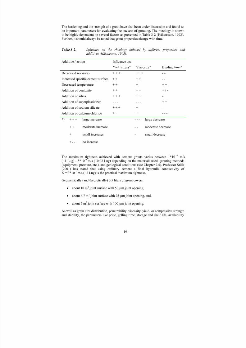
The hardening and the strength of a grout have also been under discussion and found to be important parameters for evaluating the success of grouting. The rheology is shownto be highly dependent on several factors as presented in Table 3-2 (Håkansson, 1993).Further, it should always be noted that grout properties change with time.
Table 3-2. Influence on the rheology induced by different properties and
additives (Håkansson, 1993).
Additive / action Influence on:
Yield stress* Viscosity* Binding time*
Decreased w/c-ratio + + + + + + - -
Increased specific cement surface + + + + - -
Decreased temperature + + + + +Addition of bentonite + + + + + / -
Addition of silica + + + + + -
Addition of superplasticizer - - - - - - + +
Addition of sodium silicate + + + + -
Addition of calcium chloride + + - - -
*) + + + large increase - - - large decrease
+ + moderate increase - - moderate decrease
+ small increases - small decrease
+ / - no increase
The maximum tightness achieved with cement grouts varies between 1*10 -7 m/s(~1 Lug) - 5*10-9 m/s (~0.02 Lug) depending on the materials used, grouting methods(equipment, pressure, etc.), and geological conditions (see Chapter 2.5). Professor Stille(2001) has stated that using ordinary cement a final hydraulic conductivity of
K = 3*10-7 m/s (~2 Lug) is the practical maximum tightness.
Geometrically (and theoretically) 0.5 liters of grout covers:
• about 10 m2 joint surface with 50 µm joint opening,
• about 6.7 m2 joint surface with 75 µm joint opening, and,
• about 5 m2 joint surface with 100 µm joint opening.
As well as grain size distribution, penetrability, viscosity, yield- or compressive strength
and stability, the parameters like price, gelling time, storage and shelf life, availability
and toxicity of the grout should always be taken into account when choosing the rightmaterial.
3.2.2 Additives
Cement-based grout additives can be admixtures, bentonite, mineral additives, or pozzolan, such as blast furnace slag or silica fume. Admixtures used for cementitiousgrouts are, for example:
• plasticizers and superplasticizer to reduce the water-cement ratio,
• accelerators to prevent grouts from leaking into the tunnel or ground surface,
• additives to reduce bleeding and shrinkage,
• expanding additives,
• retarders to slow hydration.
Typically material producers have their own admixture products that are recommendedfor use in the mixtures with the actual cement product.
Standard SFS-EN 197-1 for cements states that the dosage of admixtures, which areused to improve the properties of cements but not concrete, must not be more than 1%of the weight of the cement. This is not valid for additives like pozzolan, fly ash,
calcium sulfate, or silica. In the standard SFS-EN 206-1 for concrete, the amount of additives is limited to 50 g / cement-kg, unless a higher amount is known to affect thefunctional or longevity properties. However, the dosage should not exceed themanufacturers' instructions.
3.2.2.1 Additives to reduce bleeding and shrinkage
Bleeding of the grout and shrinkage of the hardened grout are problems withcementitious grouts. To avoid these, and also to increase penetrability, bentonite or
silica-based products like GroutAid can be used. Also, a low w/c-ratio (w/c = 0.7…1.0depending on the cement) reduces bleeding and shrinkage.
Bentonite is volcanic clay (smectites), which can absorb large amounts of water.Bentonite is inert and normally added to stabilize the grout against separation. Its water absorption ability is more than 500%. Since the introduction of microcements, the useof bentonite has decreased, because microcement-based grouts are much more stable,even for relatively high w/c-ratios, than OPC grouts. This is because the high specificsurface (e.g. Blaine-value) of fine-grained cements binds more water. The bentonite willalso make the grout more thixotropic. In Figure 3.4, the stabilization effect of a varyingdosage of bentonite can be seen.
Figure 3.4. Average sedimentation rate of bentonite stabilized cement suspensions
(specific surface area of cement 3500 cm2 /g. 1) Sedimentation rate
∆ H/H (%), 2) Addition of bentonite (% with reference to the weight of
cement), 3) w/c-ratio (Kutzner, 1996).
The use of GroutAid silica slurry has been found to decrease bleeding - even with quitea high w/c-ratio (Fig. 3.5). It also improves the penetration properties of the grout(Fig. 3.6). The presented tests were carried out using Ultrafine 12 cement.
0
10
20
30
40
1.0 1.5 2.0 3.0 6.0water / powder ratio
W a
t e r s e p a r a
t i o n a
f t e r
2 h r s
[ % ]
without GroutAid
with GroutAid
10%GA 25%GA 50%GA30%GA20%GA
Not tested.
Limit for stable
Figure 3.5. Water separation in grout after 2 h; Ultrafin 12 cement, varying dosage
of GroutAid (x% GA) and different w/c-ratio (Hansen et al., 2002).
Some cements, like Rheocem, are said to be stable (bleeding less than 2% within 2h)without any extra additives.
To increase the sealing effect of the grout, some expanding agents can be used. Theseare, for example, an admixture of fine-milled aluminum or aluminate sulfate andactivated coal, which releases gas bubbles while moisturizing. Further, an expansion of the grout can also be achieved by using burned chalk (CaO) or periclas (MgO). An
expansion, similar to snail dynamite, will occur when these hydrate to calcium or magnesium hydroxide.
NOTE! Even if the grout is tested in a lab and found to be stable (bleeding < 2%) itmay lose its stability (down to 10 - 15%) when a sample is disturbed. This phenomenonhas been found to occur and depends on the cement’s mineral and chemical composition(Roald, 2002).
Sand Column, d50=0.17 mm
0
10
20
30
40
0 10 20 25Content of GroutAid [%]
P e n e
t r a t i o n
i n t o S i l v e r s a n
d 1 7 [ c m
]
w/p = 1.5
w/p = 2.0
Not tested.
Figure 3.6. Effect of silica-based additive (GroutAid) on grout penetration in Sand
Column test - two water/powder –ratio is used (Hansen et al., 2002).
3.2.2.2 Plasticizers
The Most commonly used plasticizers are surface-active superplasticiziers. Withreduced cement grain size, the inter-particular forces between the grains are increased.The grains become electrically charged and attract each other. In order to break these
bindings, surface-active superplasticiziers can be used for a steric- or electrostaticrepulsion of the cement grains. Typically, the water/cement ratio with plasticizers is
between 1.0 - 1.3. Without plasticizers the w/c- ratio used is typically 3 - 4.
Both the naphthalene- or melamine-based superplasticizers can be used, though theymight have varying effects on different cement types, depending on the dominantcement compound, and also on the w/c-ratios. An admixture, such as superplasticiziers,generally affects the grouting in a positive way in that the grout can penetrate and reachfurther before hardening begins.
The accelerators can be divided into two categories:
• binder accelerators that lead to the early hardening of the grout, and
• strength accelerators that lead to an increase of the early strength.
The most common accelerator is calcium chloride, which affects both the binding andthe early strength development. For extreme cases up to 15% of calcium chloride could
be used, however, the grout will then lose the long-term stability and decay. It should benoted that calcium chloride is a retarder for aluminate and slag cements. Other earlystrength accelerators are, for example, potassium carbonate, sodium carbonate, calciumformate, triethanolamide, calcium acetate, calcium propionate, and calcium butyrate.
Binder accelerators include sodium silicate (waterglass), sodium aluminates,aluminium chloride, sodium floride, and calcium chloride. Aluminate cement inPortland cement also behaves like an accelerator.
Accelerators can be added either to the mixer to shorten the setting time or to the packer for a fast reaction. However, mixing due the relatively slow grout speed (0 - 20 l/min)might induce mixing problems and a possible reaction in packer can create plugs. Onesolution might be to use effective alcali free accelerators together with Portland cementand POC based micro and ultrafine cement (Laitinen, 2003).
Elkem AB offers a two component grouting system called MultiGrout (magnesium
cement and CaCl as an accelerator). In this system, the setting time can be adjusted to10 - 90 min.
3.2.2.4 Retarders
The use of retarders is not so common in grouting, but ligno-sulfonate can be used if needed. MBT’s Delvo®crete offers a system for grouting (and also for shotcreting). Itincludes a special stabilizer and an activator, which is added to the mixer. This systemhas been used in very warm environments where problems caused by too early setting
have been encountered. With a stabilator, a ready mixed cement based grout will remainfresh for up to 3 days.
3.2.3 Testing methods for cementitious materials
Penetrability of the grout can be analyzed by using so called “Sand Column” -test, bymeasuring a traveling length of grout through the sand filled plexiglas pipe (Fig. 3.7).
Figure 3.7. Sand Column test system for grout penetrability.
Cement manufacturers present the results of the Sand Column test as a property of their product, but typically the grain size of the filling sand and/or pumping pressure varies – actually there is no specified system for the test as can be seen in the followingexamples:
* “Ultrafine 12” with w/c=2 and 20 % GroutAid (silica based penetrator) has penetrated 85 cm into the water-filled sand “NR50” with 2 bar pressure,
* “Cem I 52.5” with w/c=1 and 2 % Rheobuild 2000 PF (dispersing agent) has penetrated 15 cm into the water-filled 0.1-0.5 mm quartz sand with 4 bar pressure, - for the same material the Marsh-cone value was 32 sec (MBT, 2001),
* “Rheocem 650” with w/c=1 and 2 % Rheobuild 2000 PF (dispersing agent) has penetrated 90 cm into the water-filled into 0.1-0.5 mm quartz sand with 4 bar pressure;
for the same material the Marsh-cone value was 32 sec (MBT, 2001).
Another test method is NES (Fig. 3.8), where grout material is pumped through theartificial smooth fracture at a constant pressure.
A third method for penetrability test is a “filter pump” (Fig. 3.9a), where grout mix ismanually sucked into the 500 mm long metal tube through a specified woven metal wirecloth (125, 75, 45 or 32 µm; ASTM E 437). Method is modified for field tests at KTH,Laboratory of Soil and Rock Mechanics. Amount of grout (in milliliters) in tube is then
measured. A bit more complicated system is developed to laboratory (Fig. 3.9b), wherewith quite low pressure of 0.5 bar a similar test is produced.
a) b)
Figure 3.9. a) Field test pump for filtration stability, b) Laboratory filter pump -
system for penetrability analysis.
Density measurements can be used to check that there are no mixing mistakes in thegrout. At site density can be measured by using a “mud balance” system (Fig. 3.10). Shrinkage of the cements can be measured from test cubes. An accepted value for shrinkage should be selected case by case – though not more than 1 - 2% in the case of grouting for high-level caverns.
The grout flow properties or viscosity are determined using a Marsh funnel (Fig. 3.11a).The funnel is first filled with 1.5 l of grout. A measuring cup containing
1 US quart (946 ml) is filled from the standard funnel and the time is measured. Cleanwater has a reading of 26 sec (US quart) or 28 sec (1 liter). A suitable value for a groutis 32 - 35 sec.
a) b)
Figure 3.11. a) The March Funnel test for viscosity analysis (Pettersson & Molin,
1999), b) Bleeding test for stability analysis
Bleeding can be measured by pouring the grout into a 1000 ml graduated glass(Fig. 3.11b). After 2 hours, the height of the bleed water (∆H) is measured. With high-level requirements, bleeding should be <2%. The ISRM Commission on Rock Grouting(1995) suggested that suspension is considered stable when the sedimentation rate ∆H/Hafter 2 hours remains under 5%.
3.3 Chemical grouts
Chemical grouts have very good penetration capability, since they are pure liquids, notdispersions. Some of them may have a viscosity almost the same as water. One could
say, “Where water can come out, acrylics can enter”. In the past, grouts containing acrylamide were used. These grouts have very good technical performance, but their environmental effect should be noted. The environmental issues are becomingincreasingly important. Some projects even require studies and environmental reports
before eventually allowing the use of acrylic grouts. If chemical grouts are needed, thereshould be close co-operation and understanding between all parties involved in the
project. When using chemical grouts, the following comments should be taken intoaccount (Riekkola et al ., 2002):
• Chemical grouts are more expensive than cementitious grouts,
• some products (pre- and final product) might be a work safety risk (irritation if touching the skin, etc…),
• longevity and stability properties not well known for all the materials – some
tests were carried out by Swedish National Research Center – SP for TACCS(Salmenhaara , 2003),
• use might require special equipment,
• due to the effective penetration, chemical grouting is faster than cement grouting(Liljestrand, 2002).
• due to the early expansion, some products do not flush away easily(Salmenhaara, 2003)
Chemical grouts can be divided into the following groups (Riekkola et al ., 2002,Vägverket, 2000):
• natriumsilicates
• acryl amid*
• lingnosulfates*, fenoplast and aminoplast*
• polyurethanes
• epoxy* and polyesterresines.Currently, polyurethane or acrylic grouts are widely in use instead of the acryl amides.These are much safer for the environment, but they have to be used under control.Polyurethane-based materials expand manifold when water is introduced. Acrylics willcure to a gel. Neither of them will be as strong as cement grouts, so they must be usedas a “second choice” and are mostly used for post-grouting fine fissures. Acrylics withan open time from a few seconds to 30 min are available on the market.
Some products, like TACSS PU foam, have very high gelling and/or expanding properties (Table 3-3), so they can be used in the case of high water leakage where
cements are flushed away (Andersson, 1998). However, the water pressure in a fractureshould be less than the expansion pressure of the grout. If there is a high ambient water pressure (>100 m), the early gelling is important to avoid the grout extruding after packer removal. Some problems due water pressure were experienced in the Lundbyroad tunnel case when using a TACSS polyurethane product for the creation of an"inner curtain" at the tunnel intrados (Bäckblom, 2002).
Due the environmental and technical reasons, some of the products (marked * in theabove list) have been abandoned in Sweden (Vägverket, 2000). Similar comments /reactions have been heard in the latest cases in Finland. It was an acryl amid gelRochaGil grout that was used in the Hallandsåsen railway tunnel site. A well-known
environmental catastrophe happened there because some grout was flushed away from
the fracture into the groundwater and poisoned nature and animals. However, RochaGilis very good material for stopping leakages with typically 98% sealing efficiency sinceacrylamides provide excellent penetration (Bäckblom, 2002). Also in Norway,acrylamide-containing grouting agents have been abandoned 1997. But, both Banverket
and Vägverket in Sweden approve polyurethane products. For example TACSS wasused in the Göta Tunnel (Liljestrand, 2002).
Table 3-3. Basic properties of some chemical grouts (Vägverket, 2000; Laitinen,
During the Romeriksporten railway tunnel construction in Oslo, chemical leakages fromtwo grouting agents (polyacrylate Meyco MP 307 and polyurethane grouting agentTACSS 020/NF) were monitored (Sverdrup et al., 2000). In a 14 km and 100 m2 tunnel,water leakage was mostly at the acceptable level except at the 1.3 km section where a
total flow of 1500 l/min was encountered. So TACSS foam was used for blockingmacropore point-leakages, which were causing a backflow of cement into the tunnel.MEYCO was used as a second agent to stop the remaining diffusely-distributed leakage.
The possibility of a relatively large local release of chemicals into the aquaticenvironment was estimated, so effluent monitoring was found to be useful for risk management. In that particular case, the average leakage of acrylic acid, methacrylicacid, and 2-hydroxyethyl methacrylate were estimated be 1.2%, 0.6%, and 0.5% (w/w),respectively, of the total 62 tons of MEYCO used. The average leakage of di-n-butyl phatalate and hexadecyl dimethyl amide were estimated to be 0.16% and<0.003% (w/w), respectively, of a total 80 tons of TACSS used. The proportions are
small, but when calculating the total kilos out of the amount of grout agents used it isquite high. However, due to the high water leakage and dilution, the environmentaleffect in the Romeriksporten case was quite limited.
3.3.1 Testing methods for chemical grouts
As presented in Table 3-3, the commonest viscosity (viscosymeter -test), stability,strength, and expansion properties test for chemical grouts is carried out by themanufacturer, mainly in the lab. Also, the density and the properties/effectiveness of
corrosion, environment, and work safety (health) should be tested and/or informed bythe material producer.
Thus, it is not common practice to do any tests in the field. Penetration and strength can be controlled via cored samples. Also, expansion (or success of mixing) of polyurethane-based materials can be controlled if some materials from the mixed grouthave been placed in a cup at the side and followed during grouting work.
It should always be remembered that the properties of chemical grouts are highlydependent on the conditions like temperature, pressure, and additives (accelerator,hardener etc…). This might induce a high variation of the penetrability and expansion
or gelling properties, even with the same product and on the same project.
NOTE! The main focus in this report has been on cement grouting since chemicalgrouts have been, and will be, the minority for rock engineering /tunneling purposes.Therefore, more detailed information of chemical grouts can be found from themanufacturers (see product list in Table 3-3) and from the literature (for example,Andersson, 1998; Karolin, 1982; Riekkola et al., 2002, Sroff & Shah, 1993, Vägverket,2000). A report by Vägverket (2000) - published in Swedish – gives a very goodsummary of the properties and environmental effects of different chemical grouts
(materials based on varying chemical compounds). Also, a study of grouting was carried
out in the Finnish technology project “Rock Engineering 2000” (Riekkola et al., 1996).In that report, a special chapter on TACSS grout material and its properties studied in alab has been included.
The main equipment & components for grouting works are presented below. It must benoted that only a few examples are presented, and there are a number of manufacturers
for each component around the world.
The grouting work starts from drilling the holes. The grout itself is mixed and agitated prior to pumping (Fig. 4.1). A hose from the pump is connected to a valve, that is, a packer, which is placed in the grouting hole. The automatic logging of the grout takehas been carried out along with the grouting.
Figure 4.1. Grouting unit ( http://www.atlascopco.com ).
4.1 Drilling Equipment
In tunneling, the grouting holes are normally made by a drilling jumbo that can be
equipped with a rod changer, so that long grouting holes can also be drilled (Fig. 4.2).The drilling rig must be capable of carrying out the appropriate grout hole pattern anddrilling capacity. It must also be suitable for controlling the drilling of a defined groutfan accurately and at penetration rates appropriate to meet the cycle time requirements.The hole diameter depends on the grouting unit – usually 50-65 mm, preferably 64 mm.
For pre-grouting in TBM tunnels, the drilling system can be assembled at the TBMmachine (Fig. 4.3).
Figure 4.2. Sandvik Tamrock Axera T12 and Atlas Copco Rocket Boomer WL3 C
drilling jumbos. At right, a rod changer system for the drilling jumbo.
Figure 4.3. Pre-grouting drilling system on a 3.5 m Robbins TBM (Garshol, 1999).
4.2 Platform
There are various platforms for grouting units. In the older, but still usable, systems, thegrouting components are just loaded on top of the mining vessel. They might even beseparate components just interlocked at the grouting site/place in the tunnel.
The modern system is to install all the equipment permanently on easily moved vehicleslike trucks (Figs. 4.4 & 4.5), in which case even multiple grouting lines can be used.Actually, increasingly often at least 2 lines with 2 pumps, preferably 3 even, arerequired – at least if continuous pre-grouting is done. This also gives more freedom and
flexibility to move inside the site or even from site to site where grouting is needed.
Figure 4.4. An Atlas Copco grouting rig with data logger at the Arlanda fast railway
link project in Stockholm ( www.masterbuilders.fi ).
Figure 4.5. A grouting unit with three pumps at the Gjelleråsen site near Oslo,
Cement and water together with additives are fed into a mixer. Several mixer typesexist. Normal paddle mixers are simple to use and rather cheap. But, since the mixing
results are not good enough for high quality grouting, these are not recommended for use. A turbo mixer is more suitable. A centrifugal pump circulates the grout at a highspeed (1300 - 1400 rpm, max. 1435 rpm) in the turbo-mixing container and creates ashearing action between the fractions for good quality mixing. However, the best resulthas been obtained by using a colloidal type mixer. In the colloidal type mixer (Fig. 4.6),shear forces are also created in the mixer housing. In the Häny system, the shear forcesare created by high turbulence in the casing, and, in Atlas Copco’s Craelius system, theshear forces are created by close tolerance between the impeller and casing(Pettersson & Molin, 1999).
Mixing time and mixing speed are important factors influencing the grout quality. Atypical mixing time for OPC is 4-5 min. The finer cements require more intense mixing.The maximum batch size is 80% of the container volume. In a colloidal mixer, thetemperature might increase several degrees due to the energy release of the shear force
braking. This might induce early hardening of the grout and should be controlled by theagitator (Pettersson & Molin, 1999). Also, mixer wearing should be controlled.
Figure 4.6. Left: Atlas Copco’s Cemix mixer in a grouting unit in Fig. 4.5 (Photo P.
The grout should always be agitated in order to keep the grout at a low viscosity and to prevent sedimentation. The agitator (Fig. 4.7) acts as a holding tank with grout ready for grouting. In the slowly revolving agitator, the grout suspensions are homogenized and
possible air bubbles removed. Its size is normally twice the size of the mixer and rotates
Two types of pumps for grouting dominate the market; the progressive cavity pump(pump without valves), and the valve type pump – that is, piston pump (Fig. 4.8).
The pump flow and pressure capacity must be sufficient to perform a satisfying grout
operation. These parameters should also be controllable and individually adjustableduring grouting work. The maximum practical pressure needed in tunnel grouting is 10MPa (100 bar). The grout flow should be high enough to avoid separation of the grout.The maximum grain size for the pump is usually varies between 3-8 mm, and should bechecked prior to grouting work.
In many cases in Norway and Sweden, the registration unit is in the field, but “back up”documentation is, in most cases, still hand written. In Finland, a manual registration is
always used. A new way is to use an automatic/computerized logging tool (Fig 4.9). Anauto logger should be easy to use with experience of a Excel and a PC. However, theSines gas storage case in Portugal showed that a logging system might be difficult touse by someone uneducated.
The logged parameters are typically flow, pressure, volume, time, real time, and holenumber. All parameters are shown in real time and display, and stored on a PC card. Itshould be possible to store the logged data and easily import it to standard programs for viewing and printouts.
The above mentioned grouting equipment is also available as a complete unit (Fig.4.10). There a mixer, agitator, pump and even a data logger, that is, standardizedcomponents, are individually mounted onto the container or stationary plants.
Packers are used for closing-off the full length or part of a borehole if the ground has to be grouted, tested, or sealed. By closing off the hole, pressure is confined in the borehole and the fluid (water or grout) is then forced into the fissures or cracks.Closing-off is achieved by expanding a seal against the hole wall. Inside the seal, thereis a tube through which the fluid is forced in and somewhere along the tube is a shut-off valve and/or a non-return valve.
Normally, the expanded seal acts as an anchor to keep the packer in the hole. Special packers with expansion shell anchors are also available.
The compression packer is tightened by mechanically expanding a rubber sleeveattached to the inner tube by turning the handle attached to the outer tube. Thecompression packer can be divided into two types:
• reusable packers
• one time use or disposable packers
With disposable packers, the sleeve has a non-return valve, which can be left in the holeafter the grout has hardened and the other parts can be reused (Fig. 4.11 and AppendixC). However, it should be remembered that removing the injection pipe too soon coulddestroy successful grouting.
Figure 4.11. Step by step installing system for disposable packer (MBT, 2001).
Inflatable or hydraulic packers are placed in the hole by grouting pipes or drill rods andthen inflated by water or air (Fig. 4.12). The inflation pressure should exceed thegrouting pressure and can be achieved by a hand pump or compressed air. After grouting and grout hardening, theoretically, the inflation pressure can be lowered andthe packer removed from the hole and reused. However, there have been many
problems due to the packers being damaged. The hydraulic packers are also quiteexpensive – a 0.5 meter packer costs about 400-2500 € each. (Løvhaugen, 2002).
The valves, hoses, and couplings should also taken into account when choosing suitableequipment and the pressure required for grouting work. Hoses should be as short as
possible. Some pressure might disappear in long hoses and in the case of the grout jamming, short hoses are more practical.
4.9 Equipment for chemical grouting
The equipment for chemical grouting is generally similar to that in cement grouting. For some materials, like polyurethanes, slightly different equipment has been recommended(see Fig. 4.13), though the grouting idea and system are equal. The type of equipmentdepends on whether one- or two-component grout is used. In some very local grouting,only a hand press or hand-pumps are needed (Appendix D). In Figure 4.14, someexamples of packers or plugs of 10-20 mm for fine crack chemical grouting are
presented. In “normal” tunnel grouting using PU foam, the standard 45-63 mm packerswith the 1/4” – ½” connections to the small PU pump hoses are used.
Figure 4.13. Airless Larius 3000 pumps for PU grouting (MBT, 2001).
Figure 4.14. Packers PPW1 for PU grouting in very small cracks (at left,
www.deneef.fi ), and Joco Composite (upper right) and Joco ”Wing plug”
5.1 GeneralPre-investigation at the construction site is needed when planning grouting. Actually,more critical tightness requirements exist, though more detailed investigations areneeded to produce good, predictable results. Experiences in Sweden and Norway showthe Lundby road tunnel in Gothenburg and Baneheia in Kristiansand to be goodexamples, and the Hallandsås and Romeriksporten railway tunnel cases as examples of extreme failure (for example,. Bäckblom, 2002; Statens Vegvesen, 2001). Although insome cases investigations can be quite difficult and also expensive, they help to producea more economical and tight cavern or tunnel. The main parameters of engineeringgeology (single fracture and fracture network characteristics), as well as hydrogeology
(conductivity, transmissivity) of construction area, are required.
General fracture properties like spacing, length, or even aperture can be evaluated quitesimply (at least to a certain degree of accuracy). But, the fracture network (boundaryconditions) or fracture fillings are more complicated, and, in many cases, these play aleading role in controlling the whole grouting process.
Several analytical and numerical methods exist to estimate the groundwater leakage (for example, Cesano, 1999; Sievänen, 2001; Satola, 2001) and are occasionally used intunnel projects. These methods (mainly based on Darcy’s theories) are usable, but varyconsiderably based on their basic assumptions, simplifications, limitations, required
geological input information, as well as usability in different environments. So, theresults are not completely comparable. Sievänen (2002) in her study considered Thiem’sapproaches to shallow and imaginary wells (see Appendix A) for deep caverns to be themost relevant.
Several evaluation systems for groutability and grout spread have also been created and presented (for example, Eriksson, 2002, Hässler et al., 1992a, Hässler et al., 1992b,Håkansson et al ., 1992; Satola, 2001; Sievänen, 2001). All of these are based on therheological laws (Newtonian or Bingham fluid model) of grout, however, geologicalfactors have been shown to play an extremely important role in grout take or groutability. Normally, the best result will be achieved if hydraulic tests, together with
conventional geological site exploration, are carried out.
In Figure 5.1, a grouting procedure is presented step by step by ISRM’s commission of rock grouting (1995). The main rule of thumb states that well-designed pre-groutingreduces the amount of inflow water and the need for post-grouting. Furthermore, thedelay time between the grouting and excavation stages, as well as different grouting
Figure 5.1. Procedure for planning and site work of grouting (ISRM, 1995).
5.2 Exploration methods for grouting need
The main aim of grouting is to reduce inflow water to a certain planned level. This can be achieved if the grout penetrates far into the rock mass, including fine fractures, andno back-flow exists.
Several geological factors and fracture properties affect the grouting work and should bedefined. Cesano (1999, 2001) has presented a system of qualitative and quantitative pre-
In qualitative investigations (Riekkola et al., 2002):
• Geological factors at the site and its surroundings are evaluated (thickness of soillayers, aquifer, etc…)
• Fracture network of rock mass with average fractures (density, aperture,orientation…),
• Location, orientation, and thickness of fracture zones, and,
• Fracture properties of fractured zone (infillings, density, aperture, orientation…).
In quantitative investigations:
• Hydraulic conductivity of a rock mass and its spatial variations,
• Level of the water table and its spatial variations.
It is reasonable that the more open and longer fractures, or higher fracture density, aremore likely to have higher inflows (Fig. 5.3). Increasing fracture density also increasegrout take, and an increasing number of fractures increases grouting time. Moreover, theSwedish experience shows that horizontal fractures parallel to tunnel lines are difficult,
but vertical leaking fractures are easier to define accurately. Experience, both in Finnishand Swedish cases, has shown that clay and chlorite infillings were associated with
fractures with higher inflow, and on the other hand, these lead to difficulties in grouting(Sievänen & Hagros, 2002; Bäckblom, 2002). The combination of filled and unfilledfractures is also difficult since flushing the filling material might create more channelsdue to the increase in pressure at the end of the grouting period.
Figure 5.3. At left: The ratio of the join aperture and frequency to the hydraulic
conductivity (Hoek & Bray, 1981), and, at right: Transmissivity,
conductivity and flow cross-section (ISRM, 1995).
Probe drilling (10 – 25 m holes) and water loss or water leakage measurements arewidely used to estimate the grouting need during the construction phase. However, thewater inflow measurements are not very accurate since, for example, hydraulicconductivity and its variation, as well as the groundwater pressure, should be known.Small inflows are also difficult to measure during the construction phase.
The location and properties of fracture zones are very important to obtain. For example,
in the Olkiluoto low and medium waste repository, which consists of 1 km of tunnelsand two silos of 30 m diameter and a demonstration hall, with 2/3 of the leakage water coming from one (RiIII-RiIV) fracture zone (Sievänen & Hagros, 2002).
In the Stripa project - grouting research for a nuclear waste repository in an old mine – it was found that rock could be divided in groutability classes based on their hydraulicconductivity (Pusch et al., 1985; Pöllä et al ., 1994). Similar classes are presented for theStockholm ring road project design (Rosengren et al ., 1996). These classes arecombined and presented in Table 5-1.
Table 5-1. Groutability hydraulic conductivity relationship (Pöllä et al., 1994;
Rosengren et al., 1996).
Hydraulic conductivity,
k (m/s)
Lugeon Comments
4x10⁻⁸ < 0.3 Some close / tight fractures.
4x10⁻⁸ - 2x10⁻⁷ 0.3 – 1.5 Only one open fracture – groutable, or a fewquite tight fractures, difficult to grout
2x10⁻⁷ - 7x10⁻⁷ 1.5 - 5 Probably several fractures, high hydraulicconductivity, quite simple to grout
7x10⁻⁷ < 5 Open fractures, very high hydraulicconductivity (possibly a high groutconsumption)
The results from the seismic methods are very seldom used for grouting design even if investigations are carried out and the results available in almost every case in Finland.Based on the research, linearity between seismic speed and hydraulic conductivity of the rock mass has been found (Fig. 5.4) - grouting may be needed if the seismic speed isless than 3,500...4,000 m/s.
Figure 5.4. Ratio of Lugeon value and seismic speed (Comité National Français,
1964). Qc stands for Q*σ c /100, and σ c uniaxial compressive strength of
Barton (2002) assumes that there may be a link between groutability and the Q-value.However, Dalmalm (2001) found no clear correlation in the two variable analyses
between Jw - Jn - Jr- Ja – values numbered according to the Q-system and the groutedvolume for the different holes at Arlandabana. According to him, there are two possibilities, either there is no correlation or the correlation could not be identified withthe data from this project, which could be the case when the rock mass is toohomogenous. For example, the Jw – value was found to be 1.0 for 99 % of the totallength of 8.6 km of tunnel in. The rock quality was also quite good, while the Q-valuevaries from 1 to 60. According to his work, a Q-index less than approximately 5 couldmean that the average grout volume would be increase (Fig. 5.5). It seems that theremight be a clearer correlation between the Q-value and grout take when the rock qualityis bad (Q < 5).
Figure 5.5. Average grout take in volumes plotted against the corresponding
Q-value, data from 100 grout holes in app. 3 fans (Dalmalm, 2001).
A modified Q for grouting (Qi) was implemented in 1991 by Johansen et al .
(Fig. 5.6). The modified equation has the same base of classification as the Q systemexcept for the Lugeon number:
Rock or tunnel grouting is carried out prior to blasting, i.e. pre-grouting, or after
blasting as post-grouting. The size of the project, as well as environmental & tightnessrequirements, determine which is used. Pre-grouting is mainly used (Fig. 5.8). Failedand still dripping sections identified after blasting are repaired by post-grouting, thus, acombination of both methods is mainly used. The main ideas and advantages or disadvantages of pre- and post-grouting are discussed in Appendix E.
Pre-grouting, single cover (3-4 blast rounds per grouting round)
Pre-grouting, double cover (always overlapping of 1-1.5 * blasting round)
Post grouting, curtain grouting at the dripping places.
Combinations of cover grouting and postgrouting.
Figure 5.8. The most typical cases in pre- and post-grouting, and a combination of
the two (Pettersson & Molin, 1999).
5.2.2 Drill pattern design and grouting order
The number, length, and spacing of holes in a grouting fan vary from case to case. Itusually depends on the size and location of the tunnel, stated requirements for tightness,and/ or environmental safety and geology. Typically 10 - 30 holes with a length of 15 - 30 m (2-4 times blasting round) and spacing 1 - 3 m is used (see Fig. 5.9 upper).Shorter holes can also be used in bad rock conditions.
Systematic grouting:66 holes, à 10...13 mHole spacing 1 m
Tightness class 2:Requirement:2.0 l/min/100 m
Systematic grouting:44 holes, à 13 mHole spacing 2 m at roof and 1 m at floor.Tightness class 3:Requirement:2.5 l/min/100 m
Systematic grouting:30 holes à 17 m
Hole spacing 2 m
Figure 5.9 Grouting drill pattern (upper) and an example of grouting classes used in
the Lundby tunnel, Sweden (MBT, 2001; Statens Vegvesen, 2001).
If the aim is just to prevent the tunnel from dripping water, grouting the roof and walls(some cases just the roof) can be enough. If the groundwater level should not sink, thefloor/bottom of the tunnel should also normally be grouted. In many cases 2/3 of the
water leakage comes from the floor and it is difficult to see due to the dirt remaining on
the tunnel bottom (Roald, 2002). In some cases, the tunnel face may also need groutingto prevent a lowering of the groundwater level and to reduce problems during drillingand charging – at least, in the face grouting of bad rock quality drifts.
In some cases like the Botniabanan railway link in eastern Sweden and the Lundby roadtunnel in Gothenburg, tunnels are divided into three grouting classes depending on therock type (Botniabanan, 2000; Vaaranta, 2002; Statens Vegvesen, 2001). The number of
boreholes in the Lundby tunnel is very high (Fig. 5.9), since extremely tightrequirements of 0.5 - 2.5 l/min/100 m for that “under-city tunnel” were set. AtStorhaugtunnel in Stavanger, pre-grouting was also done by using 30 - 72 hole/groutinground at 85 m2 tunnel (typically 62 holes) due to problems with the clay-filled jointsthat were opened by flushing (Statens Vegvesen, 2001).
The orientation and inclination of holes, that is, spacing of holes at the end of the fan,should be carefully planned and controlled at the site based on the geological
surroundings. Nowadays in Sweden, control measurements for borehole orientation aretaken. For example, at the Lundby tunnel about 20% of holes were measured by usingan inclinometer with a permitted maximum deviation of 3 - 5% (Statens Vegvesen,2001) At the Botniabanan railway link, the orientation of the grouting holes was alsomeasured and the acceptance limit for a 27 m hole was 3.5 % (Vaaranta, 2002).
Drilling should be planned in such a way that the grout is everywhere raised above thedesigned rock bolting section. That is done to avoid bolt hole penetration to the non-grouted zone and opening new channels for leaking water. If pre-grouting is also
performed in a high stress environment, it could be effective to the extended groutedzone beyond the zone where the rock mass strength is exceeded. This distance can be
evaluated based on the ratio of the rock stress and strength of a rock mass.
To extend the grouted zone to an adequate distance from the tunnel, the drilling fansshould overlap normally from 1/3 to ½ of the grout hole length. In Norway, about 9 moverlap is used (Roald, 2002). This allows the drilling of the next round to be starteddirectly after grouting work. After the first blasting round, the overlap is still about 4 mand the grout has time to harden during the drilling, charging, and hauling of thefollowing round.
The best way to drill and plan grouting holes is to use drilling jumbo together with itsown software and the registration system. During drilling, the user should write his
observations in the drilling report, like:
• penetration changes and if the anti-jamming automatic is activated,
• possible loss of the drilling water,
• color of the drilling water,
• opinion of the rock quality based on his experience.
Grouting holes should be flushed after drilling. That is typically done by using the
drilling jumbo’s flushing water. However, special devices with high pressure are
recommended and even required for use. One effective way is to use equipment that isdesigned to flush sewers.
There are several systems and ideologies concerning the order of the grouting. One
could start grouting in the bottom corner of the tunnel and continue around the patternin order, which is the typical way in Finland. In Sweden, water loss measurements arecarried out in each hole and grouting starts with the holes with highest inflow andcontinued with the next highest inflow amount and so on. This was the case, for example, in the Botniabanan tunnels. In Norway, the most used method is to start fromthe bottom holes and come up toward to the center roof hole (Hognestad, 2002; Roald,2002). Holes can be grouted one by one or in pairs depending on the number of groutingunits. However, in complicated rock, holes should be grouted one by one despite thetime lost in the project.
In bad rock condition or if the roof cover is thin, an outer zone can be grouted before
actual pre-grouting (Fig. 5.10). That procedure reduces the loss of grout and allowshigher pressures to be used.
Figure 5.10. Pre-grouting in bad rock quality with an “umbrella” (Hansen et al.,
2002).
Smooth (cautious) blasting at the area where grouting will be or has been performedmight be needed to create minimum disturbance, which is actually, more important for grouting at the tunnel floor. However, not all experts agree, but experiences fromLundby and Södra Länken road tunnels in Sweden are encouraging (Bäckblom, 2002).
A typical grouting procedure made by a contractor is shown in Appendix F.
In Finland, grouting is normally started with a high w/c-ratio being 1-3 depending onthe use of plasticizers. If the grout pressure does not increase and the grout take is some
50 kg / bore hole meter, the w/c ratio is decreased. Further, the w/c is changed until thedesired maximum grouting pressure can be reached, but normally not more thanw/c 0.5. That criterion was followed in the case of Salmisaari coal storage and Isokylätunnel on Highway VT1. Some recipes used at Salmisaari coal storage construction siteare presented in Appendix G.
The situation is very similar in Norway, where in some cases one mix of lean grout(w/c ~2.0) is pumped first to ‘grease’ the hose and rock (Statens Vegvesen, 2001). Sucha high w/c can be used if stable grout is used, but it is, however, very much sitedependent (Roald, 2002). As an example, at the Lunner – Gardemoen road tunnel inRøa grouting was started with w/c 2 till for 120 liters (one batch) and then changed to1.3/1.1 for 3000 – 4000 l/ hole, and finally to 0.55. Ultrafine cement with a maximumgrain size of 12 µm was required (Løvhaugen, 2002). Since there is no consensus onthis issue, there is also another example, such as the Jong-Asker railway tunnel wheregrouting was started using a w/c 1.1 for 300 kg and then changing to 0.9 or 0.7 andfurther to 0.5 (Rongmo, 2002).
At Botniabanan, a starting grout mix was chosen based on the water loss measurements;in the case of Lugeon < 1 => w/c 2, and if Lugeon > 1 => w/c 1 were chosen. The“starting mix” was used for about 250 kg and then changed to 0.8 for about 450 kg andfurther to “ending mix” of 0.5. Injektering 30 cement together with plasticizers (0.65 or 1 %) was used based on the stated requirements by the owner (Botniabanan, 2000;Vaaranta, 2002). Dry holes were filled using w/c 0.5, and, grouting holes were pluggedusing w/c 0.3.
Usually the maximum grouting speed used at the beginning is 20 l/min. There areseveral opinions concerning “the right value”. In Norway, the grouting speed is definedin the field, but based on the equipment capacity; in some cases, a pressure capacity of 100 bar and grouting speed of 60 l/min is required (Nomeland et al ., 2002). Dependingon the situation, 1 to 3 holes are grouted simultaneously.
5.2.4 Grouting Pressure
Grouting pressure has been a difficult issue among the experts. Divided opinions andtwo groups exist: opinions against and for high pressure. The first group firmly believesthat increasing the grouting pressure decreases work safety and breaks the rock mass bycreating new fractures and opening existing ones. The latter group of experts state thatthe increase in the pressures used is needed for better grout penetrability to create moredry tunnels, and, that no extra damage to the tunnel, or lessening of work safety, isencountered. The highest pressures used in Finland are about 3 - 4 MPa, but typically
ISRM’s grouting commission has stated in their final report (1995) that since the groutflow is dependent on the nature of the joint to be filled, the flow properties of grout, andthe effective pressure in the joint, it is logical to use as high a grouting pressure as can
be permitted. This results in the grout permeating a greater distance, hence, reducing the
need for frequent re-siting of the equipment, and reducing the cost of the operation.
In Norway, where much grouting is carried out in difficult and sensitive areas as high as8 to 9 MPa (80…90 bar) has been used without any serious problems or damages – evenclose to the surface (Roald, 2002). For example, in a railway tunnel between Jong andAsker near Oslo, a pressure of 6 MPa was mainly used, but the maximum pressure of 10MPa was stated in the grouting instructions, with the rock overburden varying from 20-40 m (Rongmo, 2002). A 10 MPa pressure for grouting equipment is also required.High pressure is needed if the fractures are tight and very low leakage is allowed intothe cavern. Usually, the main problems in the case of high grouting pressures are thecapacity of the grouting equipment (typically max. pressure for pumps are 10 MPa) and
the packer or host installations. At the Lunner – Gardemoen road tunnel through the hillwith 0-350 m overburden, a pressure of 6 - 9 MPa is used with no damage due to thehigh grouting pressure (Løvhaugen, 2002).
Sweden wants to limit pressures as in Finland. However, no disadvantages inHallandsås or the Arlanda fast railway link project were found when using high over
pressures like 5 MPa (Bäckblom, 2002).
A criterion for the maximum allowed pressure is not necessarily the depth of the tunnel(rock weight). In tight fractures, the pressure losses are significant so the influence area,and furthermore the effective force, stay very limited. The Situation is the reverse in the
case of very open fractures where in extreme case the rock’s weight should not beexceeded. One rule of thumb states, as does the theoretical point of view, that grouting
pressure must exceed twice the groundwater pressure to gain a good result and preventfingering of the grout. Another rule from Norway is that the pressure should be2.5 - 3.5 MPa higher than the groundwater pressure. Hytti (1981) presented one way toestimate a suitable grouting pressure for different rock qualities at certain depths (Fig.5.11). A similar evaluation system is also presented in ISRM (1995). There it is alsostates that the grouting pressure applied in China is twice as high as those of the“European rule of thumb” are (Fig. 5.11) with no detrimental effects.
Usually grouting is carried out using static pressure. In some specific areas where very
high sealing efficiency is required, such as a repository for nuclear waste, dynamic pressure might be usable in grouting and has been researched (Puschet al., 1985; Riekkola et al., 1996).
In dynamic grouting, both static and dynamic pressure is used. First the grout is pumpedinto the hole under steady pressure and a vibration is simultaneously carried out using,for example, percussion drilling machine. The vibration will induce shear waves, whichreduces the friction between cement particles and increases penetrability (Pöllä et al .,1994).
Figure 5.11. a) Estimation of grouting pressure: 1. Weak rock domain, 2. Good
quality rock domain, 3. ”European rule: ” 1 bar/overburden-m (Hytti,
1981), b) A state of flow around a borehole (ISRM, 1995).
The dynamic grouting has been tested in the Stripa mine project researching a suitabletool for very fine fracture grouting (Pusch et al ., 1985). Static pressures in the field test
were 1.1 - 3.3 MPa, dynamic pressure 2.5 - 3.5 MPa, and initial vibration 50 Hz. Thevibrations in the grout were measured at 20 - 200 Hz, but that rapidly decreases whengrout enters the hole.
With this method, both clay and cement suspensions were able to penetrate dozens of centimeters into the fracture with a 0.1…0.2 mm aperture. So, dynamic grouting might
be needed in the future when very low leakage is allowed in an already tight rock mass,for example, when a repository for nuclear waste will be constructed. Actually, sometests by Posiva have recently been carried out (Riekkola et al., 2002).
5.2.5 Controlling grouting and stop criteria
The grouting pressure and/or amount of grout are used as control parameters to stop thegrouting work. The limits for these parameters should be decided prior to grouting work and continuously checked, preferably by an automatic logging system (seeChapter 4).
An increase in grouting pressure during pumping indicates tight fractures– at least withthe w/c-ratio used. In some cases, increasing the w/c-ratio might still be required for asatisfactory final product.
Another signal to stop grouting or change the recipe is a grout take; if the grout take ishigh and the pressure does not increase, a joint does not get filled, and a smaller w/c-ratio should be used until the pressure increases. High grout-take in volume mightalso be due to a grout leak to the ground surface or back to the tunnel. For example, a
maximum grout take while “normal grout mix” is used could be about 50 kg of cement/drill-m or 100 l of grout/drill-m.
Normally, the stop criteria for grouting is that the grouting is completed when the setmaximum amount of grout has been reached, or the apparent grout take is less than0-3 l/min at maximum pressure. Maximum pressure must be maintained for at least 2 - 5minutes. If the permitted leakages are very low, it may be necessary to increase the timeto maintain maximum pressure (Fig. 5.12) or to just set the grout take at zero. Some
believe that 2 - 5 min is enough.
Figure 5.12. Volume increases during time in minutes. Data is from the grouting trials
at South Link project in Stockholm (Dalmalm, 2001).
Some recent examples for stopping criteria:
• Lunner – Gardemoen road tunnel at Røa, Norway: grout take 0 and pressure of 60 bar for 1 min; max grout take 4000 kg/hole (Løvhaugen, 2002),
• Jong-Asker railway tunnel, Oslo: grout take 0 and pressure of 60 bar for 5 min(Rongmo, 2002),
• Botniabanan, Örnsköldsvik, Sweden: grout take < 2 l/min for 5 min with25 bar overpressure (Vaaranta, 2002),
• Sines gas storage, Portugal (Lemminkäinen Construction): see Appendix F.
A “Grouting Intensity Number” (GIN), presented by Lombardi & Deere (1993), uses acombination of pressure and grout take in a more quantitative way:
GIN = p*V ,
Where p = grouting pressure at zero grout take
V = grout volume at zero grout flow
Grouting continues if p < pmax or V < Vmax. For example, in the case of Hallandsås(Bäckblom, 2002) the suggested values were; pmax = 55 bar (5.5 MPa), Vmax = 25 kg/m,and, GIN = 275…340. However, the GIN method is difficult to use in situ, since thegrout take is so dependent on geology (Pettersson, 2003; Hognestad, 2002, Roald,2002).
Special attention should be paid to the grouting time that should always be controlled. If the grouting lasts too long, it might start to set, so equipment might be needed to emptyand clean.
5.2.6 Post-grouting
Post- grouting is a method that is used to grout behind the face in an already excavated part. It is said to be a “passive approach”. The need for post-grouting depends on theapparent leakage amount into the tunnel and on the initial requirements. The lengths of the grouting holes are shorter and spacing denser than in pre-grouting, since grouting
targets are very local. Typically, post-grouting must be focused to the fracture zones, bad rock quality areas, or areas that are disturbed / damaged due to the blasting.
It is much more expensive to stop the water by post-grouting than by pre-grouting. Postgrouting might be even 3…10 times more expensive (a value of 20-50 was given onMBT’s homepage), which has been proven in many projects. So, post-grouting shouldalways be a repair or “second stage” strategy and in addition to pre-grouting.
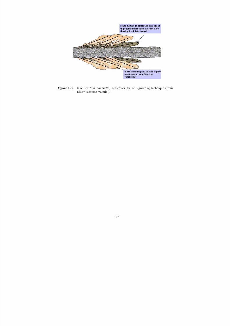
In principal, the same idea as presented in Figure 5.10 can be used to reduce groutleakage to the tunnel during post-grouting (Fig. 5.13).
6.1 Quality control of groutsBased on the European Standards for grouting (SFS-EN 12715), the properties andusability of planned and selected grout recipes should be tested and controlled, as wellas reported, before grouting work. Standardized testing methods (equipment, boundaryconditions, and analysis) should be employed to allow comparison of the characteristicsof the products provided by different suppliers. Control should be continued during the
project with specified methods and system selected beforehand. The typical controlled parameters and the tests used prior to the grouting work are:
• compressive strength,
• density by a “mud balance” system (Fig. 3.10) to control grout mixing,
• shrinkage,
• penetrability, sand column test (see Fig. 3.7), NES, filter test,
• outflow time, (Cone viscosity), Marsh cone test (see Fig. 3.11a),
• bleeding rate, sedimentation,
• setting time, Vicat test.If the conditions on site differ substantially from the laboratory conditions the test(especially the temperature test) should be conducted under in situ conditions. Thetemperature development during testing should be monitored (SFS-EN 12715).
During the construction phase, at least the following tests should be done and reported(SFS-EN 12715):
• density (Fig. 3.10) – both suspensions and microfine suspensions,
• Marsh viscosity (Fig. 3.11a) – both suspensions and microfine suspensions,• bleeding, (Fig. 3.11b) – both suspensions and microfine suspensions,
• setting time – suspensions
• grain size / sand column test (see Fig. 3.7) - microfine suspensions.
Depending on the recipe in laboratory (+20ºC), the setting of the grout should startabout 1 hour after mixing and end within 8 hours. At the site, the setting can be checked
by the “cup-test”. When a pen does not penetrate the grout, setting has started and whenthe grout does not flow out from the cup setting has stopped. Of course, this method isnot accurate but suitable for site conditions.
In Finland and Sweden, the control procedure is more or less like that presented above.In Norway, no tests have been carried out during grouting work, since themanufacturers' tests are usually accepted.
6.2 Control of grouting procedure
The whole grouting procedure, from drilling to each grout batch and personnel, should be reported including the following information:
6.3 Acceptability control and actions due to unaccepted quality
The most essential factor for controlling inflow is the hydraulic conductivity of thegrouted zone; thus, how successfully grouting has been carried out. In general, thetunnel area or diameter and the initial hydraulic conductivity of the rock mass are far less significant for inflow (Bäckblom, 2002). Furthermore, it is straightforward that thethickness of the grouted zone has an effect in the long term. For a successful “final
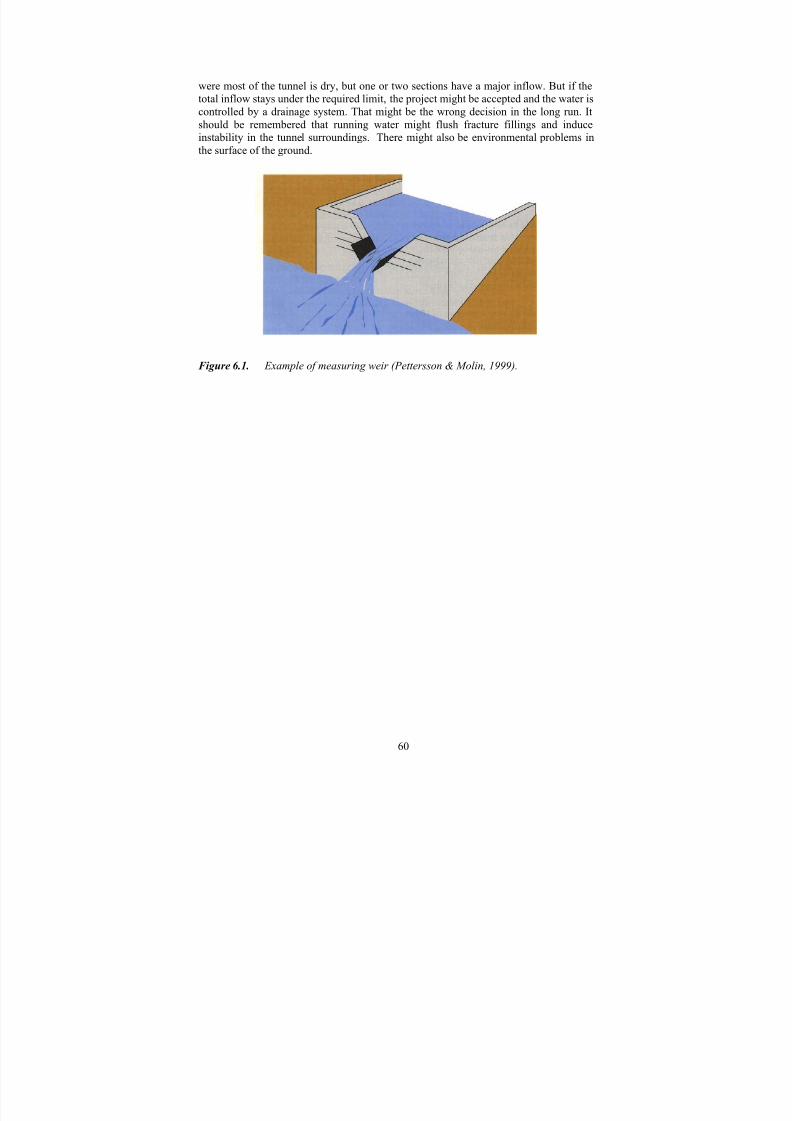
product” the installed rock bolts or other connections should never penetrate through thegrouted zone and destroy the sealing.
A dry tunnel is the best proof of successful grouting. However, the grouted zone should be tested during the construction phase by drilling a few control holes – not longer thanthe grouted zone - and measure the leakage or water loss. If the measured value ishigher than the planned maximum leaking, the grouting should be repeated partly or wholly. That procedure should be decided and planned prior to the contract so that allthe parties are well informed. That is the custom nowadays in most Swedish and
Norwegian tunnel contracts.
Another way for leakage control is to install measuring weirs (Fig. 6.1) for all or certain parts of the tunnel - for example, every 100 – 200 m. In some projects only a total
inflow has been limited and measured by using such weirs. However, there are cases
were most of the tunnel is dry, but one or two sections have a major inflow. But if thetotal inflow stays under the required limit, the project might be accepted and the water iscontrolled by a drainage system. That might be the wrong decision in the long run. Itshould be remembered that running water might flush fracture fillings and induce
instability in the tunnel surroundings. There might also be environmental problems inthe surface of the ground.
Figure 6.1. Example of measuring weir (Pettersson & Molin, 1999).
Typically, in a contract between client and contractor, grouting is divided into thefollowing divisions:
• Investigations: probe-holes price / hole meter, and water inflow measurement price/piece.
• Pre-grouting for;
* shafts: price / grouting hole meter, including drilling and grouting work andequipment.
* tunnels & halls: price / grouting hole meter or price/grout hole, includingdrilling and grouting work, equipment and material tests.
• Post-grouting is divided to;
* drilling, price / grouting hole meter for different lengths of holes,
* grouting work price / hour or shift including equipment and labor costs, or price/grout hole.
• Materials; separate prices for different grouts and additives, price/kg.
There might be some variations from case to case, mainly when:
• Separating the drilling and giving a separate price per meter for short and longholes - also for probe-hole drilling for evaluating the grouting need. That is thecase with the Botniabanan railway tunnels on the east coast of Sweden(Botniabanan, 2000; Korhonen, 2002; Vaaranta, 2002).
• Having a price per day for the grouting unit (equipment + personnel).
• Having a separate price for the special grouting materials and/or additives.
• Having a price per hour for the whole grouting work. That is good with a lowwater cement ratio, since pumping the water is not included in the material price.However, the client should have more detailed requirements for the groutingunits.
• Giving a separate price / ton for grouting around the tunnel opening.
• Giving a separate price for 2…4 main types or sizes of tunnel and if the groutingwork is done in one-face or multiple-face stages.
In some recent tunnel projects in Norway like Bragernes, Tåsen, and Storhaug (StatensVegvesen, 2001), the pricing is based on the grout-kg, including grouting work andmaterials. A separate price for drilling per meter and packers (pcs) is given. In somecases the waiting time after grouting and before new drilling is also included in grouting
price. At the Banaheia tunnel in Kristiansand, the pricing was a little special. It wasdivided into drilling price (NOK/m), grouting price that is divided into a fixed price for equipment (NOK/month) and a fixed cost for grouting work (NOK/hour), and a pricefor grout (NOK/kg) including materials, packers, etc (Statens Vegvesen, 2001).
These systems might be enough for simple cases or if a continuous pre-grouting isrequired, which is a common custom nowadays in Sweden and to a certain extent in
Norway. But, in the case of “design as you go“ systems some difficulties might occur if grouting fans differ from one from another and decisions are made at the site, the grouttake varies a lot due to very tight or very open fractures, grout material should bechanged, etc…
In some cases, as in the Sines Propane cavern project in Portugal, more detailedcontracts are required and the prices are given for:
• Grouting equipment set-up price.
• Stand-by times for grouting unit including requested labor costs, price/day.
• Grout placement, price/ton,
• For different type of tunnels, caverns, or shafts including material preparation
costs, labor costs, energy costs, follow up, as well as result reporting, andcleaning of the work area.
• For different type of grouting materials, or even,
• For different types of geological conditions (tight or large grout takes).
A more simple system is also given. For example, on Finnish Road Administrations projects for soil- and rock grouting (Tielaitos, 1991), all that is required is a price for grouting tons, without dividing that into any subdivisions. In the contract agreementsystems for mines (VMY, 1986) no divisions for grouting work have been given. These
two give the contractor a great deal of freedom and puts pressure on site design andcontrol.
In construction project quantity estimations in MAA 89 (RAKLI, 1989), a generalinstruction for rock grouting is divided into the amount of grout (m3) and the number of holes.
A few comments by Vaaranta (2002) / Lemminkäinen Construction:
• Price / hour is not a good way if no requirements for equipment are presented; the better the equipment – the higher the price.
• In the case of tight rock, the price / hour is a good system due to low cementconsumption.
• Separate price for equipment set-up is not needed as it can be handledotherwise.
• If the water/cement ratio is high, pumping the water not paid for, just theearned price/cement-kg.
Whatever pricing / purchasing system is used the early decisions regarding grouting procedure and designs, as well as strong client supervision at the site, are the mainfactors improving the quality of the final product. Furthermore, experiences from casestudies show explicitly that it is not economical to save in pre-investigations at the site – the more complex the geology or sensitive the environment the more careful andcontinuous the probe-drillings or other investigations.
Airaksinen, J.U., 1978. Maa- ja pohjavesihydrologia. Kustannusosakeyhtiö pohjoinen,Oulu (In Finnish). (Non-checked reference from Riekkola et al., 2002).
Andersson, H., 1998. Chemical Rock Grouting. An experimental study on polyurethanefoams. Chalmers Tekniska Högskola, Göteborg, Sweden. (Non-checked reference fromRiekkola et al ., 2002).
Barton, N., 2002. Some new Q-value correlations to assist in site characterisation andtunnel design. Accepted draft to Int. J. Rock Mech. Min. Sci. 5. February 2002.
Barton, N., Buen, B. & Roald, S., 2001. Strengthening the case for grouting. Tunnels
and Tunneling International , December 2001 and January 2002.
Bäckblom, G., 2002. Experience on Grouting to limit inflow to tunnels - Research anddevelopment and case studies from Sweden. Posiva Oy, Helsinki, Finland. WorkingReport 2002-18
Cesano, D., 2001. Water leakage into underground constructions in fractured rocks. Doctoral thesis at Division of Land and Water Resources, Department of Civil andEnvironmental Engineering, Royal Institute of Technology, Stockholm.
Cesano, D., 1999. Methods for prediction of groundwater flows into undergroundconstructions in hard rocks. Division of Land and Water Resources, Department of Civiland Environmental Engineering, Royal Institute of Technology, Stockholm, Sweden.
Comité National Français, 1964. La deformabilité des massifs rocheux. Analyse etcomparaison des resultats. Int. Congress on Large Dams. Vol. 8., Edinburgh, Paris.(Non-checked reference in “Barton, N., 2002. Some new Q-value correlations to assistin site characterisation and tunnel design. Accepted draft to Int. J. Rock Mech. Min. Sci. 5. February, 2002”).
Dalmalm, T., 2001. Grouting Prediction Systems for Hard Rock –Based on active
design. Licentiate Thesis. Div. of Soil and Rock Mechanics, Royal Inst. of Technology,Stockholm.
Dalmalm, T. & Janson, T., 2001. Grouting field investigation at South Link. In Proc. of 4th Nordic Rock Grouting Symposium. SveBeFo Rapport 55, Stockholm.
Eriksson, M., 2002. Prediction of grout spread and sealing effect – A probabilistic
approach. Doctoral Thesis. Div. of Soil and Rock Mechanics, Royal Inst. of Technology, Stockholm.
Fardin, N., 2001. Scale dependency, heterogeneity and anisotropy of surface roughness
of rock fractures. Licentiate Thesis. Div. of Engineering Geology, Royal Inst. of Technology, Stockholm.
Garshol, K.F., 1999. Use of pre-injection and spiling in front of hard rock TBMexcavation. In Proc. of 10th Australian Tunneling Conference, Melbourne, Victoria 21 – 24 March 1999.
Hakami, E., 1995. Aperture distribution of rock fractures. Doctoral Thesis. Div. of Engineering Geology, Royal Inst. of Technology, Stockholm.
Hansen, T.S., Nomeland, T. & Roald, S., 2002. How to make rock injections result predictable and successful the first time around. First draft of the paper to be presentedin a journal.
Hartikainen, J., 1973. Helsingin metron pohjaveden tarkkailujärjestelmä.Kalliomekaniikan päivä 1973. RGY. Vol 9. Helsinki (In Finnish). (Non-checkedreference in “Holopainen, P., 1977. Kallion tiivistäminen injektoimalla. Geotekniikanlaboratorio, tiedonanto 31. Valtion teknillinen tutkimuskeskus, Espoo”).
Hoek, E. & Bray, J., 1981. Rock Slope Engineering. Institute of Mining and Metallurgy,London. 358 p.
Hognestad, H-O., 2002. Personal discussion.
Hytti, P. 1981. Esi-injektoinnin suoritus ja sen huomioiminen urakka-asiakirjoissa.Helsinki Univ. of Technology, Otaniemi (In Finnish). (Non-checked reference in “RIL154-2, 1987. Tunneli- ja kalliorakennus II , Suomen Rakennusinsinöörien Liitto RIL,Helsinki“).
Håkansson, U., Hässler, L. & Stille, H., 1992. Rheological properties of microfinecement grouts. Tunneling and Underground Space Technology, Vol. 7, No. 4, pp.452-458.
Håkansson, U., 1993. Rheology of fresh cement based grouts. Doctoral Thesis. Div. of Soil and Rock Mechanics, Royal Inst. of Technology, Stockholm.
Hässler, L., Håkansson, U. & Stille, H., 1992a. Classification of jointed rock withemphasis on grouting. Tunnelling and Underground Space Technology, Vol. 7, No. 4,
pp. 447-452.
Hässler, L., Håkansson, U. & Stille, H., 1992b. Computer-simulated flow of grouts in jointed rock. Tunneling and Underground Space Technology, Vol. 7, No. 4, pp. 441-446.
ISRM, 1995. Commission on rock grouting , Chairman R. Widmann. Final report.International Society for Rock Mechanics.
Johansen, P.M., Løset, F., Vik, G., 1991. Erfaringsdata viser at mikrosementer vil være
et godt supplement til vanlig sementinjektion. NGI. Oslo.
Karol, R. H., 1982. Chemical grouts and their properties. Proceedings of the conferenceon Grouting in Geotechnical Engineering (ed. Wallace Hayward Baker). AmericanSociety of Civil Engineers, New York, pp. 359-377. (Non-checked reference fromRiekkola et al., 2002).
Korhonen, K., 2002. Personal discussion - site manager at Salmisaari coal storage.
Kutzner, C., 1996. Grouting of rock and soil. Balkema. Rotterdam/Brookfield.
Laitinen, A., 2003. Personal discussion.
Lanaro, F., 2001. Geometry, mechanics and transmissivity of rock fractures. DoctoralThesis. Div. of Engineering Geology, Royal Inst. of Technology, Stockholm.
Liljestrand, B., 2002. Personal discussion.
Lombardi, G. & Deere, D., 1993. Grouting design and control using the GIN-principle.Water Power & Dam Construction.
Løvhaugen, R., 2002. Personal discussion – site manager at the Lunner – Gardemoenroad tunnel, Røa.
MBT, 2001. Procure of Master Builders Technology.
Nomeland, T., Guldset, O. & Roald, S., 2002. Injeksjon i tunneler og bergrom – forslagtil arbeidsprosedyre. Elkem Materials, Multigrout 18.11.2002.
Pettersson, S-Å., 2003. Personal discussion.
Pettersson, S-Å. & Molin, M., 1999. Grouting & drilling for grouting. Atlas CopcoCraelius Ab.
Pusch, R., Börgessön, L., Karnland, O. & Hökmark, H., 1991. Final report on test 4 – Sealing of natural fine-fracture zone. Technical Report 91-26, SKB–Stripa project,Stockholm, Sweden.
Pusch, R., Erlström, M. & Börgessön, L., 1985. Sealing of rock fractures; A survey of potentially useful methods and substances. Technical Report 85-17, SKB, Stockholm.
(Non-checked reference from Dalmalm, 2001).
Pöllä, J., Riekkola, R. & Saanio, T., 1994. Stripa-projektin tiivistystutkimukset. RaporttiYJT-94-09. Voimayhtiöiden Ydinjätetoimikunta, Helsinki (in Finnish).
RAKLI, 1989. Maa 89 määrämittausohje. Suomen Rakennuttajaliitto, Helsinki (inFinnish).
Riekkola, R., Sievänen, U., Syrjänen, P. & Tolppanen, P., 2002. Kalliotilojenvesivuotojen hallinta – katsaus injektointiin. Louhinta- ja kalliotekniikanpäivät7.8.11.2002 (in Finnish).
Riekkola, R., Pöllä, J. & Satola, I., 1996. Injektointimenetelmien kehittäminen.Tutkimusraportti, projekti 2.1. Kalliorakentaminen 2000 - Teknologiahanke. RIL jaTekes, Helsinki (in Finnish).
RIL 154-2, 1987. Tunneli- ja kalliorakennus II. Suomen rakennusinsinöörien liitto,Helsinki (in Finnish).
Roald, S., 2002. Personal discussion – Professor at NTNU.
Rongmo, M., 2002. Personal discussion – site manager at Jong-Asker railway link,Oslo.
Rosengren, L., Olofsson, S-O., Israelsson, J., Bergman, M., Hakami, H., Bognar, S.,Sjöström, Ö., Salomonson, J., Hallin, A. & Wagenius, J., 1996. Förutsättningar,dimensioneringsprinciper och beräkningar avseende bergförstärkning och tätning. Norra
Länken 2, Värtan bygg. Konsortiet KM-FFNS Norra Länken 2, Stockholm.Salmenhaara, P., 2003. Personal discussion.
Satola, I., 2001. Injektointilaastien koostumusten vaikutus tunkeutuvuuteen ja
saavutettavaan tiiveystulokseen. Research Report TKK-KAL-A-30. Helsinki Univ. of Technology, Lab. of Rock Engineering, Espoo (In Finnish).
SFS-EN 197-1. Cement. Part 1: Composition, specifications and conformity criteria for common cements (Sementti. Osa 1: Tavallisten sementtien koostumus, laatuvaatimukset
ja vaatimustenmukaisuus). 27.11.2000.
SFS-EN 206-1. Concrete. Part 1: Specification, performance, production andconformity (Betoni. Osa 1: Määrittely, ominaisuudet, valmistus javaatimustenmukaisuus). 11.06.2001.
SFS-EN 12715. Pohjarakennustyöt. Injektointi (Execution of special geotechnical work.Grouting). 19.2.2001.
Shroff, A & Shah, D, 1993. Grouting technology in tunneling and dam construction. A.A. Balkema/Rotterdam/Brookfield. (Non-checked reference from Riekkola et al.,2002).
Sievänen, U., 2001. Leakage and groutability. Work Report 2001-06. Posiva Oy,Helsinki, Finland.
Sievänen, U., 2002. Preliminary estimations on groundwater inflow and groutingconditions at the Olkiluoto site. Licentiate thesis, University of Helsinki, Department of Geology.
Sievänen, U. & Hagros, A., 2002. Water inflow into underground facilities and rock grouting – experiences from Finland. Work Report 2002-26. Posiva Oy, Helsinki,Finland.
Statens Vegvesen, 2001. Injeksion – Erfaringer fra utførte tunnelprosjekter. Rapport nr.2. Statens Vegvesen, Oslo, Norway.
Stille, H., 2001. Grouting – research work and practical application. In Proc. 4th Nordic
Rock Grouting Symposium. SveBeFo Rapport 55, Stockholm.
Sverdrup, L.E., Kelley, A.E., Weideborg, M., Ødegård, K.E. & Vik, E.A., 2000.Leakage of chemicals from two grouting agents used in tunnel construction in Norway:Monitoring results from the tunnel Romeriksporten. A Journal of Environmental
Science & Technology, Vol. 34, no. 10, pp. 1914-1918.
Tahvanainen, T., 2002. Personal discussion.
Tielaitos, 1991. Määräluettelo – urakka-asiakirjat; TIEL 2242464 (In Finnish).
Vaaranta, V., 2002. Personal discussion – site manager at Botniabanan, Örnsköldsvik.
VMY, 1986. Kaivoskohteen urakkasopimusjärjestelmä. Report n:o 37, Serie B.Vuorimiesyhditys – Bergsmanna föreningen r.y. (In Finnish).
Vägverket, 2000. Tätning av bergtunnlar – förutsättningar, bedömningsgrunder ochsrategi vid planering och utforming av tätningsinsatser. Vägverket, Borlänge, Sverige.
Zimmerman, R.W., Kumar, S., Bodvarsson, G.S., 1991. Lubrication theory analysis of the permeability of rough-walled fractures. Int. Journal on Rock Mechanics and Mining
Science and Geomech. Abstracts. Vol. 28, No 4, pp. 325-331.
Äikäs, K., Hagros, A., Johansson, E., Malmlund, H., Sievänen, U., Tolppanen, P.,Ahokas, H., Heikkinen, E., Jääskeläinen, P., Ruotsalainen, P. & Saksa, P., 2000.
Engineering rock mass classification of the Olkiluoto investigation site. Posiva 2000-08,Posiva Oy, Helsinki.
One of the most used equations (Eqs. A-1 & A-2) in Sweden takes the hydraulicconductivity both before and after grouting into account if required. The friction
property of fractures by using a special and empirical based correction factor skin effect(ξ) is also notified (Rosengren et al., 1996; Sievänen, 2001 & 2002).
For non-grouted rock, there is:
ζ+
⋅⋅⋅π
R
h2ln
hK 2=Q (A-1)
And for grouted rock, the following equation is valid:
ζ+
+
⋅⋅+
+
⋅⋅π=
tR
h2ln
K
K
R
tR ln
hK 2Q
i
i
(A-2)
where,
Q = the inflow to the tunnel per meter of tunnel (m3/s, m),
K i = the hydraulic conductivity of the grouted zone (m/s),
K = the hydraulic conductivity of the rock mass outside the grouted zone (m/s),h = the hydraulic height or depth of the cavern (m)
R = the radius of the tunnel (m),
T = the extension of the grouted zone (m),
ξ = the skin factor (-) accounting for the pressure fall at the tunnel periphery(can vary from -4 – 9, typical value between 2-7)
As an example:
A tunnel (Ø 6 m) is excavated at the depth of 30 m below water table level and themean K=1·10-7 m/s, a factor of the skin-effect (ξ) is equal to 4.
So, the leaking water into the tunnel (Q) by equation (A-1) will be 15 l/min/100 m. If aK value of 1·10-8 m/s is more relevant, the leakage will be Q ≅1,5 l/min/100 m. Further,if the same tunnel is located at the depth of 100 m and K-values are equal to theaforementioned ones, the estimated leakage will be; Q ≅45 l/min/100 m and 4.5l/min/100 m, respectively.
If the same tunnel with K=1·10-7 m/s and h=30 m will be grouted and for that 3 m thick grouted zone K i =1·10-8 m/s, the leakage will be Q ≅ 2,3 l/min/100 m using equation A-2. Further, at the depth of h= 100 m Q ≅ n. 7.5 l/min/100 m.
In recent years, the use of computerized water flow analyses has been increasing sincethe speed of a normal PC computer provides a suitable platform even for a large-scaleanalysis. But, still the quality of the geological and hydrogeological information, as wellas the capability of the user, plays an important role in analyzing the results. Thesemethods might be more reliable than the analytical calculations but are slower and moreexpensive to run. Therefore, the need for, and quality of, the analyses should be decided
Several Scandinavian cases have been presented in the literature. The experiencesgained from both the grouting procedure and inflow water amounts (designed
requirements and a final result) are collected and presented in a Table on the next pageof Appendix B 2/2. Cases from tunnels and halls in Finland (Sievänen & Hagros, 2002),Sweden (Bäckblom, 2002) and Norway (Statens Vegvesen, 2001) are presented.
From the cases presented, together with the other cases in the literature, the followingconclusions can be drawn:
• Tightness requirements have increased; in traffic tunnels, a requirement of 1 - 2 l/min/100 m’s can be valid and is based on the recent catastrophes andincreased environmental aspects.
• In Sweden, and to some extent in Norway, continuous pre-grouting is carried outin traffic tunnels.
• The tight leaking limit leads to the use of micro- or ultrafine cements likeRheocem 650 & 800, Injektering 30, and Ultrafine 12. Rapid, which is typicallyused, is not enough.
• Chemical grouts, excluding polyurethane-based ones, have been more or lessabandoned due environmental and health reasons, but they are still used a littlefor post-grouting and in additives.
• The silica-based product (GroutAid) together with Ultrafine 12 cement is usedsuccessfully in high tightness requirement areas in Norway, but in Finland(Salmisaari coal storage) => silica also increases the stability and penetration of the grout.
• Also in Norway, high pressures (50…90 bar) are successfully used to increasethe penetrability/spreading of the grout; in Sweden (Arlanda fast railway link
project) and in Finland (Loviisa medium- and low-level radioactive wastestorage, and, in Salmisaari) 40 bar has also been used without any harm.
• Experiences from some sites in Sweden have shown that the normal grout take isabout 10 cement-kg / hole-m (Tahvanainen, 2002).
• Some products, like fast-hardening cements or polyurethanes used as a blocker,decrease cement consumption (Roald, 2003; Salmenhaara, 2003).
Pre-grouting is done before blasting work to tighten the rock mass around the tunnel periphery prior to blasting. The plan is mainly based on the primary site investigations.A more detailed pre-grouting plan during the excavation work is based on the probedrillings and water loss measurements made at the tunnel face. Typically, the length of the probe holes is 3-4 times the length of the blasting round; i.e. 10-20 m, and theseholes are also used as grouting holes. Especially, in the case of very demanding places,or projects with a very sensitive environment, pre-grouting is highly recommended. Themain idea, and also the most economical way, is to seal the tunnel using pre-grouting.
The advantages of pre-grouting are:
• Protection against high water inflow during excavation work,
• lowering of the water table can be limited or totally prevented,
• higher grouting pressures can be used,
• increasing of working safety
• strengthening of rock around the tunnel,
• less grout consumption,
• more controlled grout wandering, so limited grout leakage to tunnel.
• blocking of drill holes is more limited – especially in bad rock conditions
• more easy charging of blasting round.
The disadvantages of pre-grouting are:
• interruption of excavation work,
• orienting of grouting holes might be difficult since the leaking spot is not
directly seen,
• blasting and deformations around the tunnel might open joints and fracturesagain,
• expensive if done from the surface into the tunnel area.
When planning pre-grouting, the following hints should be remembered. A successful pre-grouting reaches about 5 m around the tunnel line. Also, at least the length of oneexcavation round is always grouted in front of the tunnel. The hole spacing is typically1 - 2 m.
Post- grouting is a method used to grout behind the face in an already excavated part. Itis said to be a “passive approach”. The need for post-grouting is decided based on the
leakage amount and initial requirements. Lengths of the grouting holes are shorter andspacing denser than in pre-grouting, and grouting targets are very local. Typically, post-grouting is focused on the fracture zones, bad rock quality areas, or areas that arefractured due to blasting.
Post-grouting:
• does not disturb excavation work,
• easier to plan, since rock surfaces are visible,
• grouting can be limited to a certain area where leakage exists,
• grouting of tunnel bottom is a problem,
• but, the final result is not very often successful, since the grout easily penetratesthe tunnel,
• lower pressures can be used,
• water usually finds a new route, and,
• water inflows from the tunnel floor are difficult to localize.It is much more expensive to stop the water by post-grouting, 20 - 50 times, than if pre-grouting is used in the first place, which has been proven on many projects. So, pre-grouting should always be the main strategy and post-grouting just an additionaltechnique.
Drilling is done with a 64 mm drilling bit and Data drilling rig.
Grouting hole patterns for profile 1 (access tunnel) and profile 2 (access tunnel, passing and loading shelters) are shown in Appendix drawings XXXX. Length of holes is 22 m.
In the first phase, every second hole will be drilled. If the water injection testshows a Lugeon value higher than 3, new holes near the measured hole will bedrilled.
Component characteristics:
Microcement: Rheocem 900
Superplasticizer Rheobuild 2000PF 1.5% by weight of binder
Mixing duration:
Mixing time is max. 3 minutes after microcement has been added.
Proportioning:
Water – cement ratio 1:1;
water 100 l,
cement 100 kg,
superplasticizer 1.5 kg.
Water – cement ratio 1:0.5;
water 100 l,
cement 200 kg,
superplasticizer 3 kg.
Component introducing order:
1. Water into mixer
2. Superplasticizer into mixer whilst continuously mixing
3. Microcement into mixer whilst continuously mixing
6. Keep the mix continuously agitatedThe grout must be used within 30 minutes of mixing.
Grouting phases:
Drilling is done with a 64 mm drilling bit according to annexed drilling patterns.In the first phase, every second hole will be drilled.
The grouting holes shall be flushed with water before grouting may begin.
A water injection test for each grouting hole will be carried out.
If the water penetration value is over 3 Lugeon, a set of new holes will be drilledaround (both sides) the measured hole.
The grouting will be started from the lowest hole in the face and will progresstowards the crown
Grouting is started with a water–cement ratio of 1:1. If the grouting massconsumption is over 140 l/borehole-m (bhm) and the required grouting pressurecannot be reached, the water –cement ratio is changed to 2:1. If the massconsumption is over 70 l/bhm and the required grouting pressure cannot be
reached, the water–cement ratio is changed to 1:1. If the grouting massconsumption is over 25 l/bhm and the required grouting pressure cannot bereached, the water–cement ratio is changed to 1:0.5. If the mass consumption isover 15 l/bhm and the required grouting pressure cannot be reached, grouting isstopped and the Client / Owner asked for instructions.
If during the grouting process two or more holes become connected, the packers inthe connected holes are closed.
The packers can be removed from the holes 1.5 hours after completion of thegrouting, provided that no grouting material outflows occur.
Grouting stop criteria:
Grouting will be stopped when the maximum allowed pressure has been reachedand the amount of grout going into the hole is less than 3 l per minute. Themaximum pressure must be maintained for at least 5 minutes.
Grouting will also be stopped when the grout take has reached 250 l per meter of the hole length (22 x 0.25 = 4.5 m3) unless otherwise directed by the Client /Owner.
Grouting will be stopped at the following refusal pressures (measured at the holecollar):
• 0.2 MPa at the rock surface,
• 0.5 MPa at 3-6 m depth from the rock surface,
• 1.5 MPa at 6-12 m depth from the rock surface,
• 3.0 MPa at deeper than 12 m from the rock surface.
Control of grouting:
The flow rate after grouting from the probe or control hole will be measured.
If the groundwater flow rate from the probe hole is more than Q1, a water injection test will be made at the probe hole. If the Lugeon value for 10 meterstesting length is higher than 3, a new grouting fan will be drilled as agreed withthe Client / Owner.
If grout take is over the previous limits, one mix is made using mix no. 4 and one usingno. 5. After this continue with mix no. 3. If the stop criteria are not met after three mixesof no. 3 mixture redo grouting using mixes 4 and 5.
NOTE! Before and after mixes 4 and 5, the grouting system must be washed clear,otherwise the grouts may react together and plug the system.
Kalliotunneleiden injektointikäytäntö Suomessa, Ruotsissa ja Norjassa - Kirjallisuusselvitys
Tiivistelmä
Injektoinnissa on tapahtunut runsaasti kehitystä viimevuosina. Materiaalien ja laitteistojen paraneminen onluonut mahdollisuuden yhä laadukkaammille lopputuotteille. Injektointi on kytketty keskeiseksi osaksikalliorakentamista. Myös ympäristötekijät ovat korostuneet viime vuosina ja pohjaveden haitallistaalenemista ei sallita.Sementtipohjaiset massat ovat selkeästi eniten käytetty kalliorakentamisessa. Viime vuosina on yhäenemmän siirrytty erittäin hienojakoisten sementtien käyttöön sillä tunneleiden vuotovesimäärienkiristyneet vaatimukset on johtanut tarpeeseen tiivistää yhä hienompia rakoja. Myös kemiallisiainjektointiaineita on markkinoilla runsaasti, mutta muutamien ympäristökatastrofien tapahduttua on niidenkäyttöä rajoitettu. Kemiallisia aineita on käytetty lähinnä hankalissa kohteissa jälki-injektoinnissa.
Kiristyneet tiiveysvaatimukset ja etenkin mikro- ja ultrahienojen sementtien lisääntyvä käyttö on ohjannutmyös laitteiden kehitystä. Keskeistä on ollut sekoittimine ja pumppujen kehittyminen sekä laitteistojenmuokkautuminen ”järjestelmiksi”. Myös automaattisten rekisteröintilaitteiden liittäminen osaksi
järjestelmää on auttanut laadukkaan lopputuotteen aikaansaamista.Myös suunnitteluun ja laadunvarmistukseen on viime vuosina keskitytty enemmän. Pelkkä lopputuotteenvuotomäärien toteaminen ei riitä vaan injektointireikien taipumia ja vesimenekkejä mitataan sekä porataankontrollireikiä injektoituun osuuteen. Myös injektointimassoille on esitetty omia laatuvaatimuksia, joitatarkkaillaan myös työmaalla. Suunnittelussa pyritään ottamaan alueelliset geologiset vaihtelut huomioon
jakaen tunneli vaatimustasoltaan erilaisiin osioihin.Tässä raportissa on kerätty kokemuksia ja näkemyksiä injektoinnista Suomessa, Ruotsissa ja Norjassa.Esitetty aineisto pohjautuu kirjallisuuteen ja haastatteluihin sekä kenttäkäynteihin ja kirjoittajien omiinkokemuksiin. Runsaasti tietoa ja kokemuksia on kuultu myös projektin seurantaryhmän palavereissa.
ISBN Projektinumero951-96180-3-1 (nid.)951-96180-4-X (URL: http://mtry.org/ julkaisutoiminta.htm)
Julkaisuaika Kieli Sivuja Hinta
6.6.2003 Englanti 84
Projektin nimi Toimeksiantaja(t)
INTE Tiehallinto, Ratahallintokeskus, Helsingin KaupunkiGeotekninen osasto, Elkem ASA Materials, Master Builders Oy, Lemcon Oy, YIT Rakennus Oy, ITS-Vahvistus Oy, Oy Atlas Copco Ab
Series title, number andreport code of publication
MTR Publications, no: 1
Author(s)
Pasi Tolppanen & Pauli SyrjänenTitle
Hard Rock Tunnel Grouting Practice in Finland, Sweden, and Norway
Abstract
Much development in grouting has taken place during the last decade. Improvements of groutmaterials and equipment allow for better quality final products. Grouting has become an importantand meaningful part of underground constructions. Also, the environmental requirements have
become more strict in recent years and the harmful lowering of the groundwater level is forbidden.Cementitious materials are mostly used in rock grouting in tunnels. Furthermore, due to the high-level tightness requirements, very fine-grained cements are used more since very small fracture
apertures must be grouted. Also, many different chemical grouts are on the market, but after a fewenvironmental accidents their use has been limited or even forbidden. Chemical grouts are mainlyused in very difficult places for post-grouting.A great deal of effort in grouting design and compliance control has been expended. It is not justenough to evaluate or measure the leakages of the final tunnel. The deviation and leakage of grouting holes are measured and control holes are drilled into the grouted section. Also, thelimitations and requirements for grouts are defined and checked even at the site. When planning, thevarious geological features are taken into account and tunnels are divided into sections of differentgrouting classes.Experiences and opinions on grouting in Finland, Norway, and Sweden have been collected and
printed in this report. The material presented is based on the literature, interviews, site visits, and the
authors' own experiences. Further, the discussions in the follow-up group meetings were important.Keywords
Tunnel, hard rock, groundwater, grouting, injection, instructions
Organization
Gridpoint Finland Oy
ISBN Project number 951-96180-3-1 (paperback)951-96180-4-X (URL: http://mtry.org/julkaisutoiminta.htm)
Date Language Pages Price
6.6.2003 English 84
Name of project Commissioned by
INTE Helsinki City Geotechnical Division, Finnish RailAdministration, Finnish Road Administration, ELKEMASA Materials, Master Builders Oy, Lemcon Oy, YIT