60
GRUNDFOS PRODUCT GUIDE Grundfos Direct Sensor™ Pressure transmitter
GRUNDFOS PRODUCT GUIDE
Grundfos Direct Sensor™Pressure transmitter

Table of contents
2
Grundfos Direct Sensor™
1. Pressure transmitter 3Introduction 3
2. Relative pressure transmitter, industrial (RPI)4RPI general data 4RPI 0-9 psi [0-0.6 bar] 6RPI 0-14.5 psi [0-1.0 bar] 7RPI 0-25 psi [0-1.6 bar] 8RPI 0-40 psi [0-2.5 bar] 9RPI 0-60 psi [0-4.0 bar] 10RPI 0-90 psi [0-6.0 bar] 11RPI 0-145 psi [0-10.0 bar] 12RPI 0-232 psi [0-16.0 bar] 13RPI 0-360 psi [0-25.0 bar], 14
3. Differential pressure transmitter, industrial (DPI) V.215DPI V.2 general data 15DPI 0-9 psi [0-0.6 bar] 17DPI 0-14.5 psi 18DPI 0-25 psi [0-1.6 bar] 19DPI 0-40 psi [0-2.5 bar] 20DPI 0-60 psi [0-4.0 bar] 21DPI 0-90 psi [0-6.0 bar] 22DPI 0-145 psi [0-10.0 bar] 23DPI 0-232 psi [0-16.0 bar] 24
4. Differential pressure transmitter, industrial (DPI)25DPI general data 25DPI 0-9 psi [0-0.6 bar] 27DPI 0-14.5 psi [0-1.0 bar] 28DPI 0-17.4 psi [0-1.2 bar] 29DPI 0-25 psi [0-1.6 bar] 30DPI 0-40 psi [0-2.5 bar] 31DPI 0-60 psi [0-4.0 bar] 32DPI 0-90 psi [0-6.0 bar] 33DPI 0-145 psi [0-10.0 bar] 34
5. Relative pressure sensor standard (RPS) 35RPS general data 35RPS 0-9 psi [0-0.6 bar] 37RPS 0-14.5 psi [0-1.0 bar] 38RPS 0-25 psi [0-1.6 bar] 39RPS 0-40 psi [0-2.5 bar] 40RPS 0-60 psi [0-4.0 bar] 41RPS 0-90 psi [0-6.0 bar] 42RPS 0-145 psi [0-10.0 bar] 43
6. Differential pressure sensor, standard (DPS)44DPS general data 44DPS 0-9 psi [0-0.6 bar] 46DPS 0-14.5 psi [0-1.0 bar] 47DPS 0-25 psi [0-1.6 bar] 48DPS 0-40 psi [0-2.5 bar] 49DPS 0-60 psi [0-4.0 bar] 50DPS 0-90 psi [0-6.0 bar] 51
7. Product range-RPI Transmitter 52
8. Product range - RPS sensor 53
9. Product range - DPS sensor 54
10. Product range - DPI transmitter V.2 55
11. Product range - DPI transmitter 56
12. Accessories 57Sensor interface, type SI 001 PSU 57
13. Further product documentation 58WebCAPS 58WinCAPS 59
Pres
sure
tran
smitt
er
Grundfos Direct Sensor™ 1
3
1. Pressure transmitter
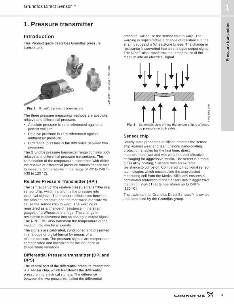
IntroductionThis Product guide describes Grundfos pressure transmitters.
Fig. 1 Grundfos pressure transmitters
The three pressure measuring methods are absolute, relative and differential pressure.• Absolute pressure is zero referenced against a
perfect vacuum.• Relative pressure is zero referenced against
ambient air pressure. • Differential pressure is the difference between two
pressures The Grundfos pressure transmitter range contains both relative and differential pressure transmitters. The combination of the temperature transmitter with either the relative or differential pressure transmitter are able to measure temperatures in the range of -22 to 248 °F [-30 to 120 °C].
Relative Pressure Transmitter (RPI)The central part of the relative pressure transmitter is a sensor chip, which transforms the pressure into electrical signals. The pressure differences between the ambient pressure and the measured pressure will cause the sensor chip to warp. The warping is registered as a change of resistance in the strain gauges of a Wheatstone bridge. The change in resistance is converted into an analogue output signal. The RPI+T will also transform the temperature of the medium into electrical signals. The signals are calibrated, conditioned and presented in analogue or digital format by means of a microprocessor. The pressure signals are temperature compensated and linearized for the influence of temperature variations.
Differential Pressure transmitter (DPI and DPS)The central part of the differential pressure transmitter is a sensor chip, which transforms the differential pressure into electrical signals. The difference between the two pressures, called the differential
pressure, will cause the sensor chip to warp. The warping is registered as a change of resistance in the strain gauges of a Wheatstone bridge. The change in resistance is converted into an analogue output signal. The DPI+T also transforms the temperature of the medium into an electrical signal. .
Fig. 2 Schematic view of how the sensor chip is affected by pressure on both sides.
Sensor chipSteady state properties of silicon protects the sensor chip against wear and tear. Lifelong nano-coating protection enables for the first time, direct measurement (wet and wet-wet) in a cost effective packaging for aggressive media. The secret is a metal-glass alloy coating, Silicoat® with an extreme resistance to corrosion. Compared to traditional sensor technologies which encapsulate the unprotected measuring cell from the Media, Silicoat® ensures a continuous protection of the Sensor Chip in aggressive media (ph 2-ph 11) at temperatures up to 248 °F [120 °C].
The trademark for Grundfos Direct Sensors is owned and controlled by the Grundfos group.
TM04
503
4 / T
M04
786
5 / T
M04
786
6
TM03
405
5 14
06
Relative pressure transm
itter, industrial (RPI)
Grundfos Direct Sensor™2
4
2. Relative pressure transmitter, industrial (RPI)
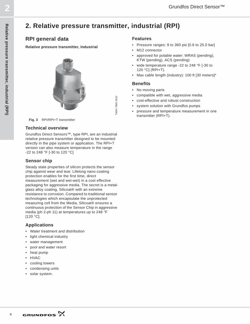
RPI general dataRelative pressure transmitter, Industrial
Fig. 3 RPI/RPI+T transmitter
Technical overview Grundfos Direct Sensors , type RPI, are an industrial relative pressure transmitter designed to be mounted directly in the pipe system or application. The RPI+T version can also measure temperature in the range-22 to 248 °F [-30 to 120 °C]
Sensor chipSteady state properties of silicon protects the sensor chip against wear and tear. Lifelong nano-coating protection enables for the first time, direct measurement (wet and wet-wet) in a cost effective packaging for aggressive media. The secret is a metal-glass alloy coating, Silicoat® with an extreme resistance to corrosion. Compared to traditional sensor technologies which encapsulate the unprotected measuring cell from the Media, Silicoat® ensures a continuous protection of the Sensor Chip in aggressive media (ph 2-ph 11) at temperatures up to 248 °F [120 °C].
Applications• Water treatment and distribution• light chemical industry• water management• pool and water resort• heat pump• HVAC• cooling towers• condensing units• solar system.
Features• Pressure ranges: 9 to 360 psi [0.6 to 25.0 bar]• M12 connector• approved for potable water: WRAS (pending),
KTW (pending), ACS (pending)• wide temperature range -22 to 248 °F [-30 to
120 °C] (RPI+T).• Max cable length (industry): 100 ft [30 meters]*
Benefits• No moving parts• compatible with wet, aggressive media• cost-effective and robust construction• system solution with Grundfos pumps• pressure and temperature measurement in one
transmitter (RPI+T).TM04
786
5 25
10
Rel
ativ
e pr
essu
re tr
ansm
itter
, ind
ustr
ial (
RPI
)
Grundfos Direct Sensor™ 2
5
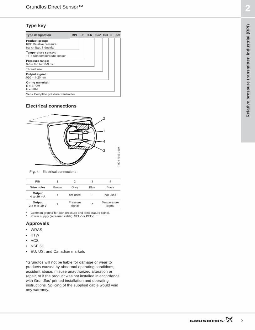
Type key
Electrical connections
Fig. 4 Electrical connections
* Common ground for both pressure and temperature signal.* Power supply (screened cable): SELV or PELV.
Approvals• WRAS• KTW• ACS• NSF 61• EU, US, and Canadian markets
*Grundfos will not be liable for damage or wear to products caused by abnormal operating conditions, accident abuse, misuse unauthorized alteration or repair, or if the product was not installed in accordance with Grundfos' printed installation and operating instructions. Splicing of the supplied cable would void any warranty.
Type designation RPI +T 0-6 G½" 020 E ,Set
Product group:RPI: Relative pressure transmitter, industrial
Temperature sensor:+T = with temperature sensor
Pressure range:0-6 = 0-6 bar 0-9 psi
Thread size
Output signal: 020 = 4-20 mA
O-ring material:E = EPDMF = FKM
Set = Complete pressure transmitter
TM04
715
6 16
10
PIN 1 2 3 4
Wire color Brown Grey Blue Black
Output 4 to 20 mA + not used - not used
Output 2 x 0 to 10 V + Pressure
signal -* Temperature signal
1
3
4
2

Relative pressure transm
itter, industrial (RPI)
Grundfos Direct Sensor™2
6
RPI 0-9 psi [0-0.6 bar]Relative pressure transmitter, industrial 0-9 psi
Fig. 5 RPI/RPI+T
Dimensions
Fig. 6 Dimensions RPI transmitter
Sensor output signals
Fig. 7 Pressure response of RPI 0-9 psi
Fig. 8 Pressure and temperature response of RPI + T
Specifications
TM04
924
0 35
10TM
04 9
237
1612
TM04
918
9 36
10TM
04 9
1890
361
0
ISO 228 - G1/2
4.33 in.
1.45 in.
1/8" NPT
0 9 psi [0.6 bar]
20 mA
4 mA
0 9 psi [0.6 bar]
10 V
32 °F [0 °C] 212 °F [100 °C]
0 V
PressureMeasuring range 0 to 9 psi [0 to 0.6 bar]Accuracy (± 1 ), 32 to 176 °F [0 to 80 °C] ± 2 % FS
Accuracy (± 1 ), -22 to 212 °F [-30 to 100 °C] ± 2.5 % FS
Response time < 100 ms (typical 50 ms)Resolution 1/1000 FS
Temperature (Only RPI with temperature sensor)Range (relative) -22 to 248 °F [-30 to 120 °C]Accuracy (± 1 ), 32 to 176 °F [0 to 80 °C] ± 1.8 °F [± 1 °C]
Accuracy (± 1 ), 32 to 212 °F [0 to 100 °C] ± 3.6 °F [± 2 °C]
Accuracy (± 1 ), 32 to 248 °F [0 to 120 °C] ± 5.4 °F [± 2.5 °C]
Response time for sensor electronics < 100 ms (typical 50 ms)
Resolution 0.18 °F [0.1 °C]
Media and environmentMedia types liquids, gasses and airMedia temperature (operation) -22 to 248 °F [-30 to 120 °C]Ambient air temperature (operation) -13 to 140 °F [-25 to 60 °C]
Storage temperature -67 to 158 °F [-55 to 70 °C]Humidity 0 to 95 % RH, non-condensingSystem burst pressure 870 psi [60 bar]
Electrical data (Only RPI without temperature sensor)Power supply RPI 12 to 30 VDCOutput signals - cut off 4 to 20 mA Power consumption 660 mW
Load impedancemax. 60 at 12.5 VDC
max. 100 at 13.3 VDCm.ax 900 at 30 VDC
Electrical data (Only RPI with temperature sensor)Power supply RPI + T 16.6 to 30 VDCOutput signals 0 to 10 VDC Max. signal cable length 98 ft [30 m]Power consumption 450 mWLoad impedance min. 10 k
Sensor materialsMeasurement element silicon-based MEMS sensorPacking material EPDM or FKM rubberSensor housing stainless steel AISI 316 L
Wetted materialscorrosion-resistant coating
EPDM or FKM rubberstainless steel AISI 316 L
Environmental standardsEnclosure class IP67Temperature cycling IEC 68-2-14Vibration (non-destructive) 20 to 2000 Hz, 10G, 4hElectromagnetic compatibility EN 61326-1
Rel
ativ
e pr
essu
re tr
ansm
itter
, ind
ustr
ial (
RPI
)
Grundfos Direct Sensor™ 2
7
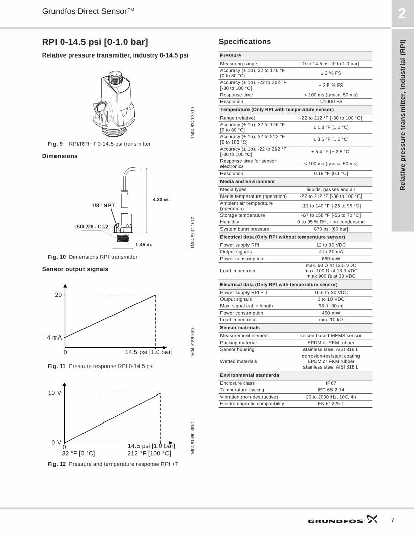
RPI 0-14.5 psi [0-1.0 bar]Relative pressure transmitter, industry 0-14.5 psi
Fig. 9 RPI/RPI+T 0-14.5 psi transmitter
Dimensions
Fig. 10 Dimensions RPI transmitter
Sensor output signals
Fig. 11 Pressure response RPI 0-14.5 psi
Fig. 12 Pressure and temperature response RPI +T
Specifications
TM04
924
0 35
10TM
04 9
237
1612
TM04
918
9 36
10TM
04 9
1890
361
0
ISO 228 - G1/2
4.33 in.
1.45 in.
1/8" NPT
0 14.5 psi [1.0 bar]
20
4 mA
0 14.5 psi [1.0 bar]
10 V
32 °F [0 °C] 212 °F [100 °C]
0 V
PressureMeasuring range 0 to 14.5 psi [0 to 1.0 bar]Accuracy (± 1 ), 32 to 176 °F [0 to 80 °C] ± 2 % FS
Accuracy (± 1 ), -22 to 212 °F [-30 to 100 °C] ± 2.5 % FS
Response time < 100 ms (typical 50 ms)Resolution 1/1000 FS
Temperature (Only RPI with temperature sensor)Range (relative) -22 to 212 °F [-30 to 100 °C]Accuracy (± 1 ), 32 to 176 °F[0 to 80 °C] ± 1.8 °F [± 1 °C]
Accuracy (± 1 ), 32 to 212 °F [0 to 100 °C] ± 3.6 °F [± 2 °C]
Accuracy (± 1 ), -22 to 212 °F [-30 to 100 °C] ± 5.4 °F [± 2.5 °C]
Response time for sensor electronics < 100 ms (typical 50 ms)
Resolution 0.18 °F [0.1 °C]
Media and environmentMedia types liquids, gasses and airMedia temperature (operation) -22 to 212 °F [-30 to 100 °C]Ambient air temperature (operation) -13 to 140 °F [-25 to 95 °C]
Storage temperature -67 to 158 °F [-55 to 70 °C]Humidity 0 to 95 % RH, non-condensingSystem burst pressure 870 psi [60 bar]
Electrical data (Only RPI without temperature sensor)Power supply RPI 12 to 30 VDCOutput signals 4 to 20 mA Power consumption 660 mW
Load impedancemax. 60 at 12.5 VDC
max. 100 at 13.3 VDCm.ax 900 at 30 VDC
Electrical data (Only RPI with temperature sensor)Power supply RPI + T 16.6 to 30 VDCOutput signals 0 to 10 VDCMax. signal cable length 98 ft [30 m]Power consumption 450 mWLoad impedance min. 10 k
Sensor materialsMeasurement element silicon-based MEMS sensorPacking material EPDM or FKM rubberSensor housing stainless steel AISI 316 L
Wetted materialscorrosion-resistant coating
EPDM or FKM rubberstainless steel AISI 316 L
Environmental standardsEnclosure class IP67Temperature cycling IEC 68-2-14Vibration (non-destructive) 20 to 2000 Hz, 10G, 4hElectromagnetic compatibility EN 61326-1

Relative pressure transm
itter, industrial (RPI)
Grundfos Direct Sensor™2
8
RPI 0-25 psi [0-1.6 bar]Relative pressure transmitter, industry 0-25 psi
Fig. 13 RPI/RPI+T 0-25 psi transmitter
Dimensions
Fig. 14 Dimensions RPI transmitter
Sensor output signals
Fig. 15 Pressure response RPI 0-25 psi
Fig. 16 Pressure and temperature response RPI +T
Specifications
TM04
924
0 35
10TM
04 9
237
1612
TM04
918
9 36
10TM
04 9
1890
361
0
ISO 228 - G1/2
4.33 in.
1.45 in.
1/8" NPT
0 25 psi [1.6 bar]
20 mA
4 mA
0 25 psi [1.6 bar]
10 V
32 °F [0 °C] 212 °F [100 °C]
0 V
PressureMeasuring range 0 to 25 psi [0 to 1.6 bar]Accuracy (± 1 ), 32 to 176 °F [0 to 80 °C] ± 2 % FS
Accuracy (± 1 ), -22 to 212 °F [-30 to 100 °C] ± 2.5 % FS
Response time < 100 ms (typical 50 ms)
Resolution 1/1000 FS
Temperature (Only RPI with temperature sensor)Range (relative) -22 to 212 °F [-30 to 100 °C]Accuracy (± 1 ), 32 to 176 °F [0 to 80 °C] ± 1.8 °F [± 1 °C]
Accuracy (± 1 ), 32 to 212 °F [0 to 100 °C] ± 3.6 °F [± 2 °C]
Accuracy (± 1 ), -22 to 212 °F [-30 to 100 °C] ± 5.4 °F [± 2.5 °C]
Response time for sensor electronics
< 100 ms(typical 50 ms)
Resolution 0.18 °F [0.1 °C]
Media and environmentMedia types liquids, gasses and airMedia temperature (operation) -22 to 212 °F [-30 to 100 °C]Ambient air temperature (operation) -13 to 140 °F [-25 to 95 °C]
Storage temperature -67 to 158 °F [-55 to 70 °C]Humidity 0 to 95 % RH, non-condensingSystem burst pressure 870 psi [60 bar]
Electrical data (Only RPI without temperature sensor)Power supply RPI 12 to 30 VDCOutput signals - cut off 4 to 20 mA Power consumption 660 mW
Load impedancemax. 60 at 12.5 VDC
max. 100 at 13.3 VDCm.ax 900 at 30 VDC
Electrical data (Only RPI with temperature sensor)Power supply RPI + T 16.6 to 30 VDCOutput signals 0 to 10 VDCMax. signal cable length 98 ft [30 m]Power consumption 450 mWLoad impedance min. 10 k
Sensor materialsMeasurement element silicon-based MEMS sensorPacking material EPDM or FKM rubberSensor housing stainless steel AISI 316 L
Wetted materialscorrosion-resistant coating
EPDM or FKM rubberstainless steel AISI 316 L
Environmental standardsEnclosure class IP67Temperature cycling IEC 68-2-14Vibration (non-destructive) 20 to 2000 Hz, 10G, 4hElectromagnetic compatibility EN 61326-1

Rel
ativ
e pr
essu
re tr
ansm
itter
, ind
ustr
ial (
RPI
)
Grundfos Direct Sensor™ 2
9
RPI 0-40 psi [0-2.5 bar]Relative pressure transmitter, industry 0-40 psi
Fig. 17 RPI/RPI+T 0-40 psi transmitter
Dimensions
Fig. 18 Dimensions RPI transmitter
Sensor output signals
Fig. 19 Pressure response of RPI 0-40 psi
Fig. 20 Pressure and temperature response of RPI +T
Specifications
TM04
924
0 35
10TM
04 9
237
1612
TM04
918
9 36
10TM
04 9
1890
361
0
ISO 228 - G1/2
4.33 in.
1.45 in.
1/8" NPT
0 40 psi [2.5 bar]
20 mA
4 mA
0 40 psi [2.5 bar]
10 V
32 °F [0 °C] 212 °F [100 °C]
0 V
PressureMeasuring range 0 to 40 psi [0 to 2.5 bar]Accuracy (± 1 ), 32 to 176 °F [0 to 80 °C] ± 2 % FS
Accuracy (± 1 ), -22 to 212 °F [-30 to 100 °C] ± 2.5 % FS
Response time < 100 ms (typical 50 ms)Resolution 1/1000 FS
Temperature (Only RPI with temperature sensor)Range (relative) -22 to 212 °F [-30 to 100 °C]Accuracy (± 1 ), 32 to 176 °F [0 to 80 °C] ± 1.8 °F [± 1 °C]
Accuracy (± 1 ), 32 to 212 °F [0 to 100 °C] ± 3.6 °F [± 2 °C]
Accuracy (± 1 ), -22 to 212 °F [-30 to 100 °C] ± 5.4 °F [± 2.5 °C]
Response time for sensor electronics
< 100 ms(typical 50 ms)
Resolution 0.18 °F [0.1 °C]
Media and environmentMedia types liquids, gasses and airMedia temperature (operation) -22 to 212 °F [-30 to 100 °C]Ambient air temperature (operation) -13 to 140 °F [-25 to 95 °C]
Storage temperature -67 to 158 °F [-55 to 70 °C]Humidity 0 to 95 % RH, non-condensingSystem burst pressure 870 psi [60 bar]
Electrical data (Only RPI without temperature sensor)Power supply RPI 12 to 30 VDCOutput signals 4 to 20 mA Power consumption 660 mW
Load impedancemax. 60 at 12.5 VDC
max. 100 at 13.3 VDCm.ax 900 at 30 VDC
Electrical data (Only RPI with temperature sensor)Power supply RPI + T 16.6 to 30 VDCOutput signals 0 to 10 VDC xxxMax. signal cable length 98 ft [30 m]Power consumption 450 mWLoad impedance min. 10 k
Sensor materialsMeasurement element silicon-based MEMS sensorPacking material EPDM or FKM rubberSensor housing stainless steel AISI 316 L
Wetted materialscorrosion-resistant coating
EPDM or FKM rubberstainless steel AISI 316 L
Environmental standardsEnclosure class IP67Temperature cycling IEC 68-2-14Vibration (non-destructive) 20 to 2000 Hz, 10G, 4hElectromagnetic compatibility EN 61326-1
Relative pressure transm
itter, industrial (RPI)
Grundfos Direct Sensor™2
10
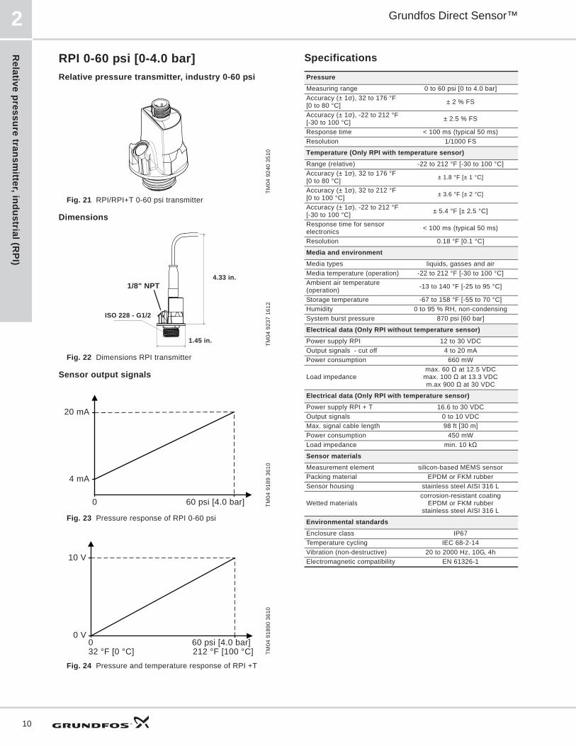
RPI 0-60 psi [0-4.0 bar]Relative pressure transmitter, industry 0-60 psi
Fig. 21 RPI/RPI+T 0-60 psi transmitter
Dimensions
Fig. 22 Dimensions RPI transmitter
Sensor output signals
Fig. 23 Pressure response of RPI 0-60 psi
Fig. 24 Pressure and temperature response of RPI +T
Specifications
TM04
924
0 35
10TM
04 9
237
1612
TM04
918
9 36
10TM
04 9
1890
361
0
ISO 228 - G1/2
4.33 in.
1.45 in.
1/8" NPT
0 60 psi [4.0 bar]
20 mA
4 mA
0 60 psi [4.0 bar]
10 V
32 °F [0 °C] 212 °F [100 °C]
0 V
PressureMeasuring range 0 to 60 psi [0 to 4.0 bar]Accuracy (± 1 ), 32 to 176 °F [0 to 80 °C] ± 2 % FS
Accuracy (± 1 ), -22 to 212 °F [-30 to 100 °C] ± 2.5 % FS
Response time < 100 ms (typical 50 ms)Resolution 1/1000 FS
Temperature (Only RPI with temperature sensor)Range (relative) -22 to 212 °F [-30 to 100 °C]Accuracy (± 1 ), 32 to 176 °F [0 to 80 °C] ± 1.8 °F [± 1 °C]
Accuracy (± 1 ), 32 to 212 °F [0 to 100 °C] ± 3.6 °F [± 2 °C]
Accuracy (± 1 ), -22 to 212 °F [-30 to 100 °C] ± 5.4 °F [± 2.5 °C]
Response time for sensor electronics < 100 ms (typical 50 ms)
Resolution 0.18 °F [0.1 °C]
Media and environmentMedia types liquids, gasses and airMedia temperature (operation) -22 to 212 °F [-30 to 100 °C]Ambient air temperature (operation) -13 to 140 °F [-25 to 95 °C]
Storage temperature -67 to 158 °F [-55 to 70 °C]Humidity 0 to 95 % RH, non-condensingSystem burst pressure 870 psi [60 bar]
Electrical data (Only RPI without temperature sensor)Power supply RPI 12 to 30 VDCOutput signals - cut off 4 to 20 mA Power consumption 660 mW
Load impedancemax. 60 at 12.5 VDC
max. 100 at 13.3 VDCm.ax 900 at 30 VDC
Electrical data (Only RPI with temperature sensor)Power supply RPI + T 16.6 to 30 VDCOutput signals 0 to 10 VDC Max. signal cable length 98 ft [30 m]Power consumption 450 mWLoad impedance min. 10 k
Sensor materialsMeasurement element silicon-based MEMS sensorPacking material EPDM or FKM rubberSensor housing stainless steel AISI 316 L
Wetted materialscorrosion-resistant coating
EPDM or FKM rubberstainless steel AISI 316 L
Environmental standardsEnclosure class IP67Temperature cycling IEC 68-2-14Vibration (non-destructive) 20 to 2000 Hz, 10G, 4hElectromagnetic compatibility EN 61326-1
Rel
ativ
e pr
essu
re tr
ansm
itter
, ind
ustr
ial (
RPI
)
Grundfos Direct Sensor™ 2
11
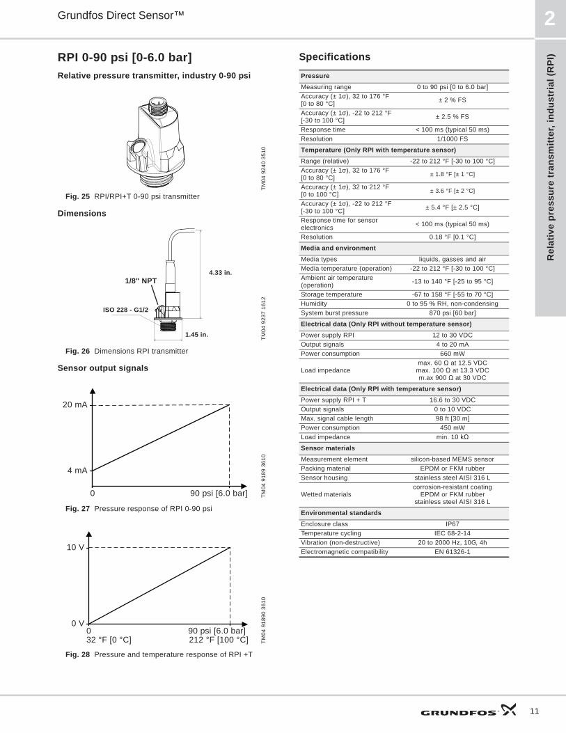
RPI 0-90 psi [0-6.0 bar]Relative pressure transmitter, industry 0-90 psi
Fig. 25 RPI/RPI+T 0-90 psi transmitter
Dimensions
Fig. 26 Dimensions RPI transmitter
Sensor output signals
Fig. 27 Pressure response of RPI 0-90 psi
Fig. 28 Pressure and temperature response of RPI +T
Specifications
TM04
924
0 35
10TM
04 9
237
1612
TM04
918
9 36
10TM
04 9
1890
361
0
ISO 228 - G1/2
4.33 in.
1.45 in.
1/8" NPT
0 90 psi [6.0 bar]
20 mA
4 mA
0 90 psi [6.0 bar]
10 V
32 °F [0 °C] 212 °F [100 °C]
0 V
PressureMeasuring range 0 to 90 psi [0 to 6.0 bar]Accuracy (± 1 ), 32 to 176 °F [0 to 80 °C] ± 2 % FS
Accuracy (± 1 ), -22 to 212 °F [-30 to 100 °C] ± 2.5 % FS
Response time < 100 ms (typical 50 ms)Resolution 1/1000 FS
Temperature (Only RPI with temperature sensor)Range (relative) -22 to 212 °F [-30 to 100 °C]Accuracy (± 1 ), 32 to 176 °F [0 to 80 °C] ± 1.8 °F [± 1 °C]
Accuracy (± 1 ), 32 to 212 °F [0 to 100 °C] ± 3.6 °F [± 2 °C]
Accuracy (± 1 ), -22 to 212 °F [-30 to 100 °C] ± 5.4 °F [± 2.5 °C]
Response time for sensor electronics < 100 ms (typical 50 ms)
Resolution 0.18 °F [0.1 °C]
Media and environmentMedia types liquids, gasses and airMedia temperature (operation) -22 to 212 °F [-30 to 100 °C]Ambient air temperature (operation) -13 to 140 °F [-25 to 95 °C]
Storage temperature -67 to 158 °F [-55 to 70 °C]Humidity 0 to 95 % RH, non-condensingSystem burst pressure 870 psi [60 bar]
Electrical data (Only RPI without temperature sensor)Power supply RPI 12 to 30 VDCOutput signals 4 to 20 mA Power consumption 660 mW
Load impedancemax. 60 at 12.5 VDC
max. 100 at 13.3 VDCm.ax 900 at 30 VDC
Electrical data (Only RPI with temperature sensor)Power supply RPI + T 16.6 to 30 VDCOutput signals 0 to 10 VDC Max. signal cable length 98 ft [30 m]Power consumption 450 mWLoad impedance min. 10 k
Sensor materialsMeasurement element silicon-based MEMS sensorPacking material EPDM or FKM rubberSensor housing stainless steel AISI 316 L
Wetted materialscorrosion-resistant coating
EPDM or FKM rubberstainless steel AISI 316 L
Environmental standardsEnclosure class IP67Temperature cycling IEC 68-2-14Vibration (non-destructive) 20 to 2000 Hz, 10G, 4hElectromagnetic compatibility EN 61326-1
Relative pressure transm
itter, industrial (RPI)
Grundfos Direct Sensor™2
12
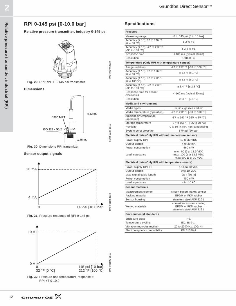
RPI 0-145 psi [0-10.0 bar]Relative pressure transmitter, industry 0-145 psi
Fig. 29 RPI/RPI+T 0-145 psi transmitter
Dimensions
Fig. 30 Dimensions RPI transmitter
Sensor output signals
Fig. 31 Pressure response of RPI 0-145 psi
Fig. 32 Pressure and temperature response ofRPI +T 0-10.0
Specifications
TM04
924
0 35
10TM
04 9
237
1612
TM04
918
9 36
10TM
04 9
1890
361
0
ISO 228 - G1/2
4.33 in.
1.45 in.
1/8" NPT
0 145psi [10.0 bar]
20 mA
4 mA
0 145 psi [10 bar]
10 V
32 °F [0 °C] 212 °F [100 °C]
0 V
PressureMeasuring range 0 to 145 psi [0 to 10 bar]Accuracy (± 1 ), 32 to 176 °F [0 to 80 °C] ± 2 % FS
Accuracy (± 1 ), -22 to 212 °F [-30 to 100 °C] ± 2.5 % FS
Response time < 100 ms (typical 50 ms)Resolution 1/1000 FS
Temperature (Only RPI with temperature sensor)Range (relative) -22 to 212 °F [-30 to 100 °C]Accuracy (± 1 ), 32 to 176 °F [0 to 80 °C] ± 1.8 °F [± 1 °C]
Accuracy (± 1 ), 32 to 212 °F [0 to 100 °C] ± 3.6 °F [± 2 °C]
Accuracy (± 1 ), -22 to 212 °F [-30 to 100 °C] ± 5.4 °F [± 2.5 °C]
Response time for sensor electronics < 100 ms (typical 50 ms)
Resolution 0.18 °F [0.1 °C]
Media and environmentMedia types liquids, gasses and airMedia temperature (operation) -22 to 212 °F [-30 to 100 °C]Ambient air temperature (operation) -13 to 140 °F [-25 to 95 °C]
Storage temperature -67 to 158 °F [-55 to 70 °C]Humidity 0 to 95 % RH, non-condensingSystem burst pressure 870 psi [60 bar]
Electrical data (Only RPI without temperature sensor)Power supply RPI 12 to 30 VDCOutput signals 4 to 20 mA Power consumption 660 mW
Load impedancemax. 60 at 12.5 VDC
max. 100 at 13.3 VDCm.ax 900 at 30 VDC
Electrical data (Only RPI with temperature sensor)Power supply RPI + T 16.6 to 30 VDCOutput signals 0 to 10 VDC Max. signal cable length 98 ft [30 m]Power consumption 450 mWLoad impedance min. 10 k
Sensor materialsMeasurement element silicon-based MEMS sensorPacking material EPDM or FKM rubberSensor housing stainless steel AISI 316 L
Wetted materialscorrosion-resistant coating
EPDM or FKM rubberstainless steel AISI 316 L
Environmental standardsEnclosure class IP67Temperature cycling IEC 68-2-14Vibration (non-destructive) 20 to 2000 Hz, 10G, 4hElectromagnetic compatibility EN 61326-1
Rel
ativ
e pr
essu
re tr
ansm
itter
, ind
ustr
ial (
RPI
)
Grundfos Direct Sensor™ 2
13
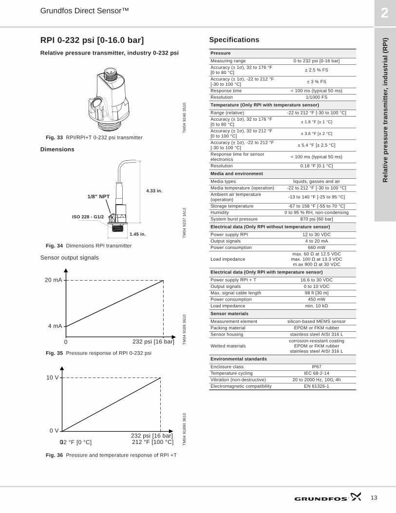
RPI 0-232 psi [0-16.0 bar]Relative pressure transmitter, industry 0-232 psi
Fig. 33 RPI/RPI+T 0-232 psi transmitter
Dimensions
Fig. 34 Dimensions RPI transmitter
Sensor output signals
Fig. 35 Pressure response of RPI 0-232 psi
Fig. 36 Pressure and temperature response of RPI +T
Specifications
TM04
924
0 35
10TM
04 9
237
1612
TM04
918
9 36
10TM
04 9
1890
361
0
ISO 228 - G1/2
4.33 in.
1.45 in.
1/8" NPT
0 232 psi [16 bar]
20 mA
4 mA
0232 psi [16 bar]
10 V
32 °F [0 °C] 212 °F [100 °C]
0 V
PressureMeasuring range 0 to 232 psi [0-16 bar]Accuracy (± 1 ), 32 to 176 °F [0 to 80 °C] ± 2.5 % FS
Accuracy (± 1 ), -22 to 212 °F [-30 to 100 °C] ± 3 % FS
Response time < 100 ms (typical 50 ms)Resolution 1/1000 FS
Temperature (Only RPI with temperature sensor)Range (relative) -22 to 212 °F [-30 to 100 °C]Accuracy (± 1 ), 32 to 176 °F [0 to 80 °C] ± 1.8 °F [± 1 °C]
Accuracy (± 1 ), 32 to 212 °F [0 to 100 °C] ± 3.6 °F [± 2 °C]
Accuracy (± 1 ), -22 to 212 °F [-30 to 100 °C] ± 5.4 °F [± 2.5 °C]
Response time for sensor electronics < 100 ms (typical 50 ms)
Resolution 0.18 °F [0.1 °C]
Media and environmentMedia types liquids, gasses and airMedia temperature (operation) -22 to 212 °F [-30 to 100 °C]Ambient air temperature (operation) -13 to 140 °F [-25 to 95 °C]
Storage temperature -67 to 158 °F [-55 to 70 °C]Humidity 0 to 95 % RH, non-condensingSystem burst pressure 870 psi [60 bar]
Electrical data (Only RPI without temperature sensor)Power supply RPI 12 to 30 VDCOutput signals 4 to 20 mA Power consumption 660 mW
Load impedancemax. 60 at 12.5 VDC
max. 100 at 13.3 VDCm.ax 900 at 30 VDC
Electrical data (Only RPI with temperature sensor)Power supply RPI + T 16.6 to 30 VDCOutput signals 0 to 10 VDC Max. signal cable length 98 ft [30 m]Power consumption 450 mWLoad impedance min. 10 k
Sensor materialsMeasurement element silicon-based MEMS sensorPacking material EPDM or FKM rubberSensor housing stainless steel AISI 316 L
Wetted materialscorrosion-resistant coating
EPDM or FKM rubberstainless steel AISI 316 L
Environmental standardsEnclosure class IP67Temperature cycling IEC 68-2-14Vibration (non-destructive) 20 to 2000 Hz, 10G, 4hElectromagnetic compatibility EN 61326-1

Relative pressure transm
itter, industrial (RPI)
Grundfos Direct Sensor™2
14
RPI 0-360 psi [0-25.0 bar], Relative pressure transmitter, industry 0-360 psi
Fig. 37 RPI/RPI+T 0-360 psi transmitter
Dimensions
Fig. 38 Dimensions RPI transmitter
Sensor output signals
Fig. 39 Pressure response of RPI 0-360 psi
Fig. 40 Pressure and temperature response of RPI +T
Specifications
TM04
924
0 35
10TM
04 9
237
1612
TM04
918
9 36
10TM
04 9
1890
361
0
ISO 228 - G1/2
4.33 in.
1.45 in.
1/8" NPT
0 360 psi [25 bar]
20 mA
4 mA
0 360 psi [25 bar]
10 V
32 °F [0 °C] 212 °F [100 °C]
0 V
PressureMeasuring range 0 to 360 psi [0 to 25 bar]Accuracy (± 1 ), 32 to 176 °F [0 to 80 °C] ± 2.5 % FS
Accuracy (± 1 ), -22 to 212 °F [-30 to 100 °C] ± 3 % FS
Response time < 100 ms (typical 50 ms)Resolution 1/1000 FS
Temperature (Only RPI with temperature sensor)Range (relative) -22 to 212 °F [-30 to 100 °C]Accuracy (± 1 ), 32 to 176 °F [0 to 80 °C] ± 1.8 °F [± 1 °C]
Accuracy (± 1 ), 32 to 212 °F [0 to 100 °C] ± 3.6 °F [± 2 °C]
Accuracy (± 1 ), -22 to 212 °F -30 to 100 °C] ± 5.4 °F [± 2.5 °C]
Response time for sensor electronics < 100 ms (typical 50 ms)
Resolution 0.18 °F [0.1 °C]
Media and environmentMedia types liquids, gasses and airMedia temperature (operation) -22 to 212 °F [-30 to 100 °C]Ambient air temperature (operation) -13 to 140 °F [-25 to 95 °C]
Storage temperature -67 to 158 °F [-55 to 70 °C]Humidity 0 to 95 % RH, non-condensingSystem burst pressure 870 psi [60 bar]
Electrical data (Only RPI without temperature sensor)Power supply RPI 12 to 30 VDCOutput signals 4 to 20 mA Power consumption 660 mW
Load impedancemax. 60 at 12.5 VDC
max. 100 at 13.3 VDCm.ax 900 at 30 VDC
Electrical data (Only RPI with temperature sensor)Power supply RPI + T 16.6 to 30 VDCOutput signals 0 to 10 VDC Max. signal cable length 98 ft [30 m]Power consumption 450 mWLoad impedance min. 10 k
Sensor materialsMeasurement element silicon-based MEMS sensorPacking material EPDM or FKM rubberSensor housing stainless steel AISI 316 L
Wetted materialscorrosion-resistant coating
EPDM or FKM rubberstainless steel AISI 316 L
Environmental standardsEnclosure class IP67Temperature cycling IEC 68-2-14Vibration (non-destructive) 20 to 2000 Hz, 10G, 4hElectromagnetic compatibility EN 61326-1

Diff
eren
tial p
ress
ure
tran
smitt
er, i
ndus
tria
l (D
PI) V
.2
Grundfos Direct Sensor™ 3
15
3. Differential pressure transmitter, industrial (DPI) V.2
DPI V.2 general dataDifferential pressure transmitter, industrial V.2
Fig. 41 DPI transmitter
Technical overview Grundfos Direct Sensors , type DPI, are an industrial differential pressure transmitter, designed to be mounted directly in the pipe system (V.2). The DPI +T version can also measure temperature in the range 32 to 212 °F [0 to 100 °C]. The DPI have a standard M12 connector.
Sensor chipSteady state properties of silicon protects the sensor chip against wear and tear. Lifelong nano-coating protection enables for the first time, direct measurement (wet and wet-wet) in a cost effective packaging for aggressive media. The secret is a metal-glass alloy coating, Silicoat® with an extreme resistance to corrosion. Compared to traditional sensor technologies which encapsulate the unprotected measuring cell from the Media, Silicoat® ensures a continuous protection of the Sensor Chip in aggressive media (ph 2-ph 11) at temperatures up to 248 °F [120 °C].
Applications• Water treatment and distribution• light chemical industry• water management• pool and water resort• heating• heat pump• air conditioning• cooling towers• condensing units• solar system.
Features• Pressure range: 9 to 232 psi• approved for potable water: WRAS (pending),
KTW (pending), ACS (pending)• wide temperature range 32 to 212 °F [0 to 100 °C]
(DPI +T).• 1/8" NPT-SW 27 capillary tube connection for P2
connection• Max cable length (industry): 100 ft [30 meters]*
Benefits• No moving parts• compatible with wet, aggressive media• cost-effective and robust construction• system solution with Grundfos pumps• Pressure and temperature measurement in one
transmitter.
Approvals• WRAS• KTW• ACS• NSF 61• EU, US, and Canadian markets
TM04
786
6 25
10

Differential pressure transm
itter, industrial (DPI) V.2
Grundfos Direct Sensor™3
16
Type key
Electrical connections
Fig. 42 Electrical connections
* Common ground for both pressure and temperature signal.* Power supply (screened cable): SELV or PELV.
*Grundfos will not be liable for damage or wear to products caused by abnormal operating conditions, accident abuse, misuse unauthorized alteration or repair, or if the product was not installed in accordance with Grundfos' printed installation and operating instructions. Splicing of the supplied cable would void any warranty.
DPI +T 0-6 G½" 020 E ,Set
Type
Temperature sensor:+T = with temperature Sensor
Flow range [m3/h]
Thread size
Output signal: 020 = 4-20mA
O-ring material:E = EPDMF = FKM
Set = Complete pressure transmitter
TM04
715
6 16
10
PIN 1 2 3 4
Wire color Brown Grey Blue Black
Output 4 - 20 mA + not used - not used
Output 2 x 0 - 10 V + Pressure
signal -* Temperature signal
1
3
4
2
Diff
eren
tial p
ress
ure
tran
smitt
er, i
ndus
tria
l (D
PI) V
.2
Grundfos Direct Sensor™ 3
17
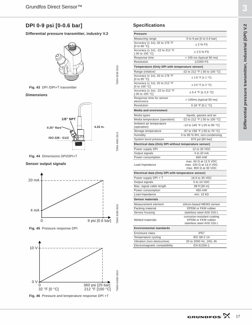
DPI 0-9 psi [0-0.6 bar]Differential pressure transmitter, industry V.2
Fig. 43 DPI /DPI+T transmitter
Dimensions
Fig. 44 Dimensions DPI/DPI+T
Sensor output signals
Fig. 45 Pressure response DPI
Fig. 46 Pressure and temperature response DPI +T
Specifications
TM04
923
9 35
10TM
04 4
963
2612
TM04
918
9 36
10TM
04 9
1890
361
0
4.33 in.
1/8" NPT
0.25" flare
ISO 228 - G1/2
0 9 psi [0.6 bar]
20 mA
4 mA
0 360 psi [25 bar]
10 V
32 °F [0 °C] 212 °F [100 °C]
0 V
PressureMeasuring range 0 to 9 psi [0 to 0.6 bar]Accuracy (± 1 ), 32 to 176 °F [0 to 80 °C] ± 2 % FS
Accuracy (± 1 ), -22 to 212 °F [-30 to 100 °C] ± 2.5 % FS
Response time < 100 ms (typical 50 ms)Resolution 1/1000 FS
Temperature (Only DPI with temperature sensor)Range (relative) -22 to 212 °F [-30 to 100 °C]Accuracy (± 1 ), 32 to 176 °F [0 to 80 °C] ± 1.8 °F [± 1 °C]
Accuracy (± 1 ), 32 to 212 °F [0 to 100 °C] ± 3.6 °F [± 2 °C]
Accuracy (± 1 ), -22 to 212 °F [-30 to 100 °C] ± 5.4 °F [± 2.5 °C]
Response time for sensor electronics < 100ms (typical 50 ms)
Resolution 0.18 °F [0.1 °C]
Media and environmentMedia types liquids, gasses and airMedia temperature (operation) -22 to 212 °F [-30 to 100 °C]Ambient air temperature (operation) -13 to 140 °F [-25 to 95 °C]
Storage temperature -67 to 158 °F [-55 to 70 °C]Humidity 0 to 95 % RH, non-condensingSystem burst pressure 870 psi [60 bar]
Electrical data (Only DPI without temperature sensor)Power supply DPI 12 to 30 VDCOutput signals 4 to 20 mA Power consumption 660 mW
Load impedancemax. 60 at 12.5 VDC
max. 100 at 13.3 VDCmax. 900 at 30 VDC
Electrical data (Only DPI with temperature sensor)Power supply DPI + T 16.6 to 30 VDCOutput signals 0 to 10 VDC Max. signal cable length 98 ft [30 m]Power consumption 450 mWLoad impedance min. 10 k
Sensor materialsMeasurement element silicon-based MEMS sensorPacking material EPDM or FKM rubberSensor housing stainless steel AISI 316 L
Wetted materialscorrosion-resistant coating
EPDM or FKM rubberstainless steel AISI 316 L
Environmental standardsEnclosure class IP67Temperature cycling IEC 68-2-14Vibration (non-destructive) 20 to 2000 Hz, 10G, 4hElectromagnetic compatibility EN 61326-1
Differential pressure transm
itter, industrial (DPI) V.2
Grundfos Direct Sensor™3
18
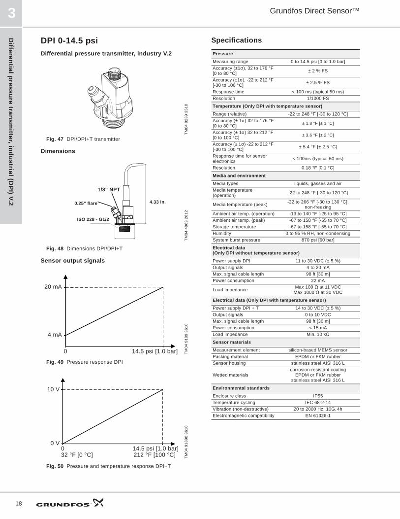
DPI 0-14.5 psiDifferential pressure transmitter, industry V.2
Fig. 47 DPI/DPI+T transmitter
Dimensions
Fig. 48 Dimensions DPI/DPI+T
Sensor output signals
Fig. 49 Pressure response DPI
Fig. 50 Pressure and temperature response DPI+T
Specifications
TM04
923
9 35
10TM
04 4
963
2612
TM04
918
9 36
10TM
04 9
1890
361
0
4.33 in.
1/8" NPT
0.25" flare
ISO 228 - G1/2
0 14.5 psi [1.0 bar]
20 mA
4 mA
0 14.5 psi [1.0 bar]
10 V
32 °F [0 °C] 212 °F [100 °C]
0 V
PressureMeasuring range 0 to 14.5 psi [0 to 1.0 bar]Accuracy (±1 ), 32 to 176 °F [0 to 80 °C] ± 2 % FS
Accuracy (±1 ), -22 to 212 °F [-30 to 100 °C] ± 2.5 % FS
Response time < 100 ms (typical 50 ms)Resolution 1/1000 FS
Temperature (Only DPI with temperature sensor)Range (relative) -22 to 248 °F [-30 to 120 °C]Accuracy (± 1 ) 32 to 176 °F[0 to 80 °C] ± 1.8 °F [± 1 °C]
Accuracy (± 1 ) 32 to 212 °F [0 to 100 °C] ± 3.6 °F [± 2 °C]
Accuracy (± 1 ) -22 to 212 °F [-30 to 100 °C] ± 5.4 °F [± 2.5 °C]
Response time for sensor electronics < 100ms (typical 50 ms)
Resolution 0.18 °F [0.1 °C]
Media and environmentMedia types liquids, gasses and airMedia temperature (operation) -22 to 248 °F [-30 to 120 °C]
Media temperature (peak) -22 to 266 °F [-30 to 130 °C],non-freezing
Ambient air temp. (operation) -13 to 140 °F [-25 to 95 °C]Ambient air temp. (peak) -67 to 158 °F [-55 to 70 °C]Storage temperature -67 to 158 °F [-55 to 70 °C]Humidity 0 to 95 % RH, non-condensingSystem burst pressure 870 psi [60 bar]
Electrical data (Only DPI without temperature sensor)Power supply DPI 11 to 30 VDC (± 5 %)Output signals 4 to 20 mA Max. signal cable length 98 ft [30 m]Power consumption 22 mA
Load impedance Max 100 at 11 VDCMax 1000 at 30 VDC
Electrical data (Only DPI with temperature sensor)Power supply DPI + T 14 to 30 VDC (± 5 %)Output signals 0 to 10 VDC Max. signal cable length 98 ft [30 m]Power consumption < 15 mALoad impedance Min. 10 k
Sensor materialsMeasurement element silicon-based MEMS sensorPacking material EPDM or FKM rubberSensor housing stainless steel AISI 316 L
Wetted materialscorrosion-resistant coating
EPDM or FKM rubberstainless steel AISI 316 L
Environmental standardsEnclosure class IP55Temperature cycling IEC 68-2-14Vibration (non-destructive) 20 to 2000 Hz, 10G, 4hElectromagnetic compatibility EN 61326-1
Diff
eren
tial p
ress
ure
tran
smitt
er, i
ndus
tria
l (D
PI) V
.2
Grundfos Direct Sensor™ 3
19
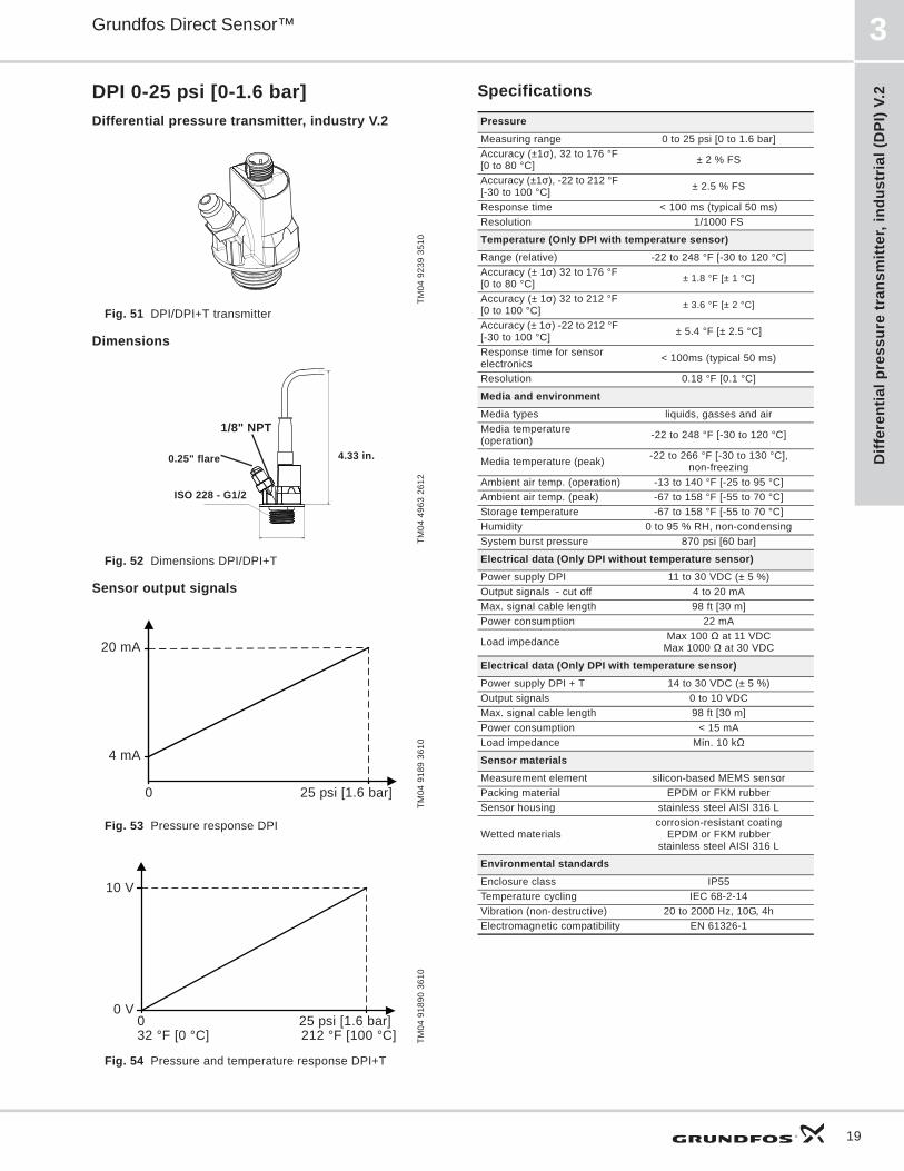
DPI 0-25 psi [0-1.6 bar]Differential pressure transmitter, industry V.2
Fig. 51 DPI/DPI+T transmitter
Dimensions
Fig. 52 Dimensions DPI/DPI+T
Sensor output signals
Fig. 53 Pressure response DPI
Fig. 54 Pressure and temperature response DPI+T
Specifications
TM04
923
9 35
10TM
04 4
963
2612
TM04
918
9 36
10TM
04 9
1890
361
0
4.33 in.
1/8" NPT
0.25" flare
ISO 228 - G1/2
0 25 psi [1.6 bar]
20 mA
4 mA
0 25 psi [1.6 bar]
10 V
32 °F [0 °C] 212 °F [100 °C]
0 V
PressureMeasuring range 0 to 25 psi [0 to 1.6 bar]Accuracy (±1 ), 32 to 176 °F [0 to 80 °C] ± 2 % FS
Accuracy (±1 ), -22 to 212 °F [-30 to 100 °C] ± 2.5 % FS
Response time < 100 ms (typical 50 ms)Resolution 1/1000 FS
Temperature (Only DPI with temperature sensor)Range (relative) -22 to 248 °F [-30 to 120 °C]Accuracy (± 1 ) 32 to 176 °F [0 to 80 °C] ± 1.8 °F [± 1 °C]
Accuracy (± 1 ) 32 to 212 °F [0 to 100 °C] ± 3.6 °F [± 2 °C]
Accuracy (± 1 ) -22 to 212 °F [-30 to 100 °C] ± 5.4 °F [± 2.5 °C]
Response time for sensor electronics < 100ms (typical 50 ms)
Resolution 0.18 °F [0.1 °C]
Media and environmentMedia types liquids, gasses and airMedia temperature (operation) -22 to 248 °F [-30 to 120 °C]
Media temperature (peak) -22 to 266 °F [-30 to 130 °C], non-freezing
Ambient air temp. (operation) -13 to 140 °F [-25 to 95 °C]Ambient air temp. (peak) -67 to 158 °F [-55 to 70 °C]Storage temperature -67 to 158 °F [-55 to 70 °C]Humidity 0 to 95 % RH, non-condensingSystem burst pressure 870 psi [60 bar]
Electrical data (Only DPI without temperature sensor)Power supply DPI 11 to 30 VDC (± 5 %)Output signals - cut off 4 to 20 mA Max. signal cable length 98 ft [30 m]Power consumption 22 mA
Load impedance Max 100 at 11 VDCMax 1000 at 30 VDC
Electrical data (Only DPI with temperature sensor)Power supply DPI + T 14 to 30 VDC (± 5 %)Output signals 0 to 10 VDC Max. signal cable length 98 ft [30 m]Power consumption < 15 mALoad impedance Min. 10 k
Sensor materialsMeasurement element silicon-based MEMS sensorPacking material EPDM or FKM rubberSensor housing stainless steel AISI 316 L
Wetted materialscorrosion-resistant coating
EPDM or FKM rubberstainless steel AISI 316 L
Environmental standardsEnclosure class IP55Temperature cycling IEC 68-2-14Vibration (non-destructive) 20 to 2000 Hz, 10G, 4hElectromagnetic compatibility EN 61326-1

Differential pressure transm
itter, industrial (DPI) V.2
Grundfos Direct Sensor™3
20
DPI 0-40 psi [0-2.5 bar]Differential pressure transmitter, industry V.2
Fig. 55 DPI/DPI+T transmitter
Dimensions
Fig. 56 Dimensions DPI/DPI+T
Sensor output signals
Fig. 57 Pressure response DPI
Fig. 58 Pressure and temperature response DPI+T
Specifications
TM04
923
9 35
10TM
04 4
963
2612
TM04
918
9 36
10TM
04 9
1890
361
0
4.33 in.
1/8" NPT
0.25" flare
ISO 228 - G1/2
0 40. psi [2.5 bar]
20 mA
4 mA
0 40 psi [2.5 bar]
10 V
32 °F [0 °C] 212 °F [100 °C]
0 V
PressureMeasuring range 0 to 40 psi [0 to 2.5 bar]Accuracy (±1 ), 32 to 176 °F [0 to 80 °C] ± 2 % FS
Accuracy (±1 ), -22 to 212 °F [-30 to 100 °C] ± 2.5 % FS
Response time < 100 ms (typical 50 ms)Resolution 1/1000 FS
Temperature (Only DPI with temperature sensor)Range (relative) -22 to 248 °F [-30 to 120 °C]Accuracy (± 1 ) 32 to 176 °F [0 to 80 °C] ± 1.8 °F [± 1 °C]
Accuracy (± 1 ) 32 to 212 °F [0 to 100 °C] ± 3.6 °F [± 2 °C]
Accuracy (± 1 ) -22 to 212 °F [-30 to 100 °C] ± 5.4 °F [± 2.5 °C]
Response time for sensor electronics < 100ms (typical 50 ms)
Resolution 0.18 °F [0.1 °C]
Media and environmentMedia types liquids, gasses and airMedia temperature (operation) -22 to 248 °F [-30 to 120 °C]
Media temperature (peak) -22 to 266 °F [-30 to 130 °C], non-freezing
Ambient air temp. (operation) -13 to 140 °F [-25 to 95 °C]Ambient air temp. (peak) -67 to 158 °F [-55 to 70 °C]Storage temperature -67 to 158 °F [-55 to 70 °C]Humidity 0 to 95 % RH, non-condensingSystem burst pressure 870 psi [60 bar]
Electrical data (Only DPI without temperature sensor)Power supply DPI 11 to 30 VDC (± 5 %)Output signals - cut off 4 to 20 mA Max. signal cable length 98 ft [30 m]Power consumption 22 mA
Load impedance Max 100 at 11 VDCMax 1000 at 30 VDC
Electrical data (Only DPI with temperature sensor)Power supply DPI + T 14 to 30 VDC (± 5 %)Output signals 0 to 10 VDC Max. signal cable length 98 ft [30 m]Power consumption < 15 mALoad impedance Min. 10 k
Sensor materialsMeasurement element silicon-based MEMS sensorPacking material EPDM or FKM rubberSensor housing stainless steel AISI 316 L
Wetted materialscorrosion-resistant coating
EPDM or FKM rubberstainless steel AISI 316 L
Environmental standardsEnclosure class IP55Temperature cycling IEC 68-2-14Vibration (non-destructive) 20 to 2000 Hz, 10G, 4hElectromagnetic compatibility EN 61326-1

Diff
eren
tial p
ress
ure
tran
smitt
er, i
ndus
tria
l (D
PI) V
.2
Grundfos Direct Sensor™ 3
21
DPI 0-60 psi [0-4.0 bar]Differential pressure transmitter, industry V.2
Fig. 59 DPI/DPI+T transmitter
Dimensions
Fig. 60 Dimensions DPI/DPI+T
Sensor output signals
Fig. 61 Pressure response DPI
Fig. 62 Pressure and temperature response DPI+T
Specifications
TM04
923
9 35
10TM
04 4
963
2612
TM04
918
9 36
10TM
04 9
1890
361
0
4.33 in.
1/8" NPT
0.25" flare
ISO 228 - G1/2
0 60 psi [4.0 bar]
20 mA
4 mA
0 60 psi [4.0 bar]
10 V
32 °F [0 °C] 212 °F [100 °C]
0 V
PressureMeasuring range 0 to 60 psi [0 to 4.0 bar]Accuracy (±1 ), 32 to 176 °F [0 to 80 °C] ± 2 % FS
Accuracy (±1 ), -22 to 212 °F [-30 to 100 °C] ± 2.5 % FS
Response time < 100 ms (typical 50 ms)Resolution 1/1000 FS
Temperature (Only DPI with temperature sensor)Range (relative) -22 to 248 °F [-30 to 120 °C]Accuracy (± 1 ) 32 to 176 °F [0 to 80 °C] ± 1.8 °F [± 1 °C]
Accuracy (± 1 ) 32 to 212 °F [0 to 100 °C] ± 3.6 °F [± 2 °C]
Accuracy (± 1 ) -22 to 212 °F [-30 to 100 °C] ± 5.4 °F [± 2.5 °C]
Response time for sensor electronics < 100ms (typical 50 ms)
Resolution 0.18 °F [0.1 °C]
Media and environmentMedia types liquids, gasses and airMedia temperature (operation) -22 to 248 °F [-30 to 120 °C]
Media temperature (peak) -22 to 266 °F [-30 to 130 °C],non-freezing
Ambient air temp. (operation) -13 to 140 °F [-25 to 95 °C]Ambient air temp. (peak) -67 to 158 °F [-55 to 70 °C]Storage temperature -67 to 158 °F [-55 to 70 °C]Humidity 0 to 95 % RH, non-condensingSystem burst pressure 870 psi [60 bar]
Electrical data (Only DPI without temperature sensor)Power supply DPI 11 to 30 VDC (± 5 %)Output signals - cut off 4 to 20 m - 21 mAMax. signal cable length 98 ft [30 m]Power consumption 22 mA
Load impedance Max 100 at 11 VDCMax 1000 at 30 VDC
Electrical data (Only DPI with temperature sensor)Power supply DPI + T 14 to 30 VDC (± 5 %)Output signals 0 to 10 VDC Max. signal cable length 98 ft [30 m]Power consumption < 15 mALoad impedance Min. 10 k
Sensor materialsMeasurement element silicon-based MEMS sensorPacking material EPDM or FKM rubberSensor housing stainless steel AISI 316 L
Wetted materialscorrosion-resistant coating
EPDM or FKM rubberstainless steel AISI 316 L
Environmental standardsEnclosure class IP55Temperature cycling IEC 68-2-14Vibration (non-destructive) 20 to 2000 Hz, 10G, 4hElectromagnetic compatibility EN 61326-1

Differential pressure transm
itter, industrial (DPI) V.2
Grundfos Direct Sensor™3
22
DPI 0-90 psi [0-6.0 bar]Differential pressure transmitter, industry V.2
Fig. 63 DPI/DPI+T transmitter
Dimensions
Fig. 64 Dimensions DPI/DPI+T
Sensor output signals
Fig. 65 Pressure response DPI
Fig. 66 Pressure and temperature response DPI+T
Specifications
TM04
923
9 35
10TM
04 4
963
2612
TM04
918
9 36
10TM
04 9
1890
361
0
4.33 in.
1/8" NPT
0.25" flare
ISO 228 - G1/2
0 90 psi [6.0 bar]
20 mA
4 mA
0 90 psi [6.0 bar]
10 V
32 °F [0 °C] 212 °F [100 °C]
0 V
PressureMeasuring range 0 to 90psi [0 to 6.0 bar]Accuracy (±1 ), 32 to 176 °F [0 to 80 °C] ± 2 % FS
Accuracy (±1 ), -22 to 212 °F [-30 to 100 °C] ± 2.5 % FS
Response time < 100 ms (typical 50 ms)Resolution 1/1000 FS
Temperature (Only DPI with temperature sensor)Range (relative) -22 to 248 °F [-30 to 120 °C]Accuracy (± 1 ) 32 to 176 °F [0 to 80 °C] ± 1.8 °F [± 1 °C]
Accuracy (± 1 ) 32 to 212 °F [0 to 100 °C] ± 3.6 °F [± 2 °C]
Accuracy (± 1 ) -22 to 212 °F [-30 to 100 °C] ± 5.4 °F [± 2.5 °C]
Response time for sensor electronics < 100ms (typical 50 ms)
Resolution 0.18 °F [0.1 °C]
Media and environmentMedia types liquids, gasses and airMedia temperature (operation) -22 to 248 °F [-30 to 120 °C]
Media temperature (peak) -22 to 266 °F [-30 to 130 °C],non-freezing
Ambient air temp. (operation) -13 to 140 °F [-25 to 95 °C]Ambient air temp. (peak) -67 to 158 °F [-55 to 70 °C]Storage temperature -67 to 158 °F [-55 to 70 °C]Humidity 0 to 95 % RH, non-condensingSystem burst pressure 870 psi [60 bar]
Electrical data (Only DPI without temperature sensor)Power supply DPI 11 to 30 VDC (± 5 %)Output signals 4 to 20 mA Max. signal cable length 98 ft [30 m]Power consumption 22 mA
Load impedance Max 100 at 11 VDCMax 1000 at 30 VDC
Electrical data (Only DPI with temperature sensor)Power supply DPI + T 14 to 30 VDC (± 5 %)Output signals 0 to 10 VDC Max. signal cable length 98 ft [30 m]Power consumption < 15 mALoad impedance Min. 10 k
Sensor materialsMeasurement element silicon-based MEMS sensorPacking material EPDM or FKM rubberSensor housing stainless steel AISI 316 L
Wetted materialscorrosion-resistant coating
EPDM or FKM rubberstainless steel AISI 316 L
Environmental standardsEnclosure class IP55Temperature cycling IEC 68-2-14Vibration (non-destructive) 20 to 2000 Hz, 10G, 4hElectromagnetic compatibility EN 61326-1

Diff
eren
tial p
ress
ure
tran
smitt
er, i
ndus
tria
l (D
PI) V
.2
Grundfos Direct Sensor™ 3
23
DPI 0-145 psi [0-10.0 bar]Differential pressure transmitter, industry V.2
Fig. 67 DPI/DPI+T transmitter
Dimensions
Fig. 68 Dimensions DPI/DPI+T
Sensor output signals
Fig. 69 Pressure response DPI
Fig. 70 Pressure and temperature response DPI+T
Specifications
TM04
923
9 35
10TM
04 4
963
2612
TM04
918
9 36
10TM
04 9
1890
361
0
4.33 in.
1/8" NPT
0.25" flare
ISO 228 - G1/2
0 145 psi [10.0 bar]
20 mA
4 mA
0 145 psi [10 bar]
10 V
32 °F [0 °C] 212 °F [100 °C]
0 V
PressureMeasuring range 0 to 145 psi [0 to 10.0 bar]Accuracy (±1 ), 32 to 176 °F [0 to 80 °C] ± 2 % FS
Accuracy (±1 ), -22 to 212 °F [-30 to 100 °C] ± 2.5 % FS
Response time < 100 ms (typical 50 ms)Resolution 1/1000 FS
Temperature (Only DPI with temperature sensor)Range (relative) -22 to 248 °F [-30 to 120 °C]Accuracy (± 1 ) 32 to 176 °F [0 to 80 °C] ± 1.8 °F [± 1 °C]
Accuracy (± 1 ) 32 to 212 °F [0 to 100 °C] ± 3.6 °F [± 2 °C]
Accuracy (± 1 ) -22 to 212 °F [-30 to 100 °C] ± 5.4 °F [± 2.5 °C]
Response time for sensor electronics < 100ms (typical 50 ms)
Resolution 0.18 °F [0.1 °C]
Media and environmentMedia types liquids, gasses and airMedia temperature (operation) -22 to 248 °F [-30 to 120 °C]
Media temperature (peak) -22 to 266 °F [-30 to 130 °C], non-freezing
Ambient air temp. (operation) -13 to 140 °F [-25 to 95 °C]Ambient air temp. (peak) -67 to 158 °F [-55 to 70 °C]Storage temperature -67 to 158 °F [-55 to 70 °C]Humidity 0 to 95 % RH, non-condensingSystem burst pressure 870 psi [60 bar]
Electrical data (Only DPI without temperature sensor)Power supply DPI 11 to 30 VDC (± 5 %)Output signals - cut off 4 to 20 mA Max. signal cable length 98 ft [30 m]Power consumption 22 mA
Load impedance Max 100 at 11 VDCMax 1000 at 30 VDC
Electrical data (Only DPI with temperature sensor)Power supply DPI + T 14 to 30 VDC (± 5 %)Output signals 0 to 10 VDC Max. signal cable length 98 ft [30 m]Power consumption < 15 mALoad impedance Min. 10 k
Sensor materialsMeasurement element silicon-based MEMS sensorPacking material EPDM or FKM rubberSensor housing stainless steel AISI 316 L
Wetted materialscorrosion-resistant coating
EPDM or FKM rubberstainless steel AISI 316 L
Environmental standardsEnclosure class IP55Temperature cycling IEC 68-2-14Vibration (non-destructive) 20 to 2000 Hz, 10G, 4hElectromagnetic compatibility EN 61326-1
Differential pressure transm
itter, industrial (DPI) V.2
Grundfos Direct Sensor™3
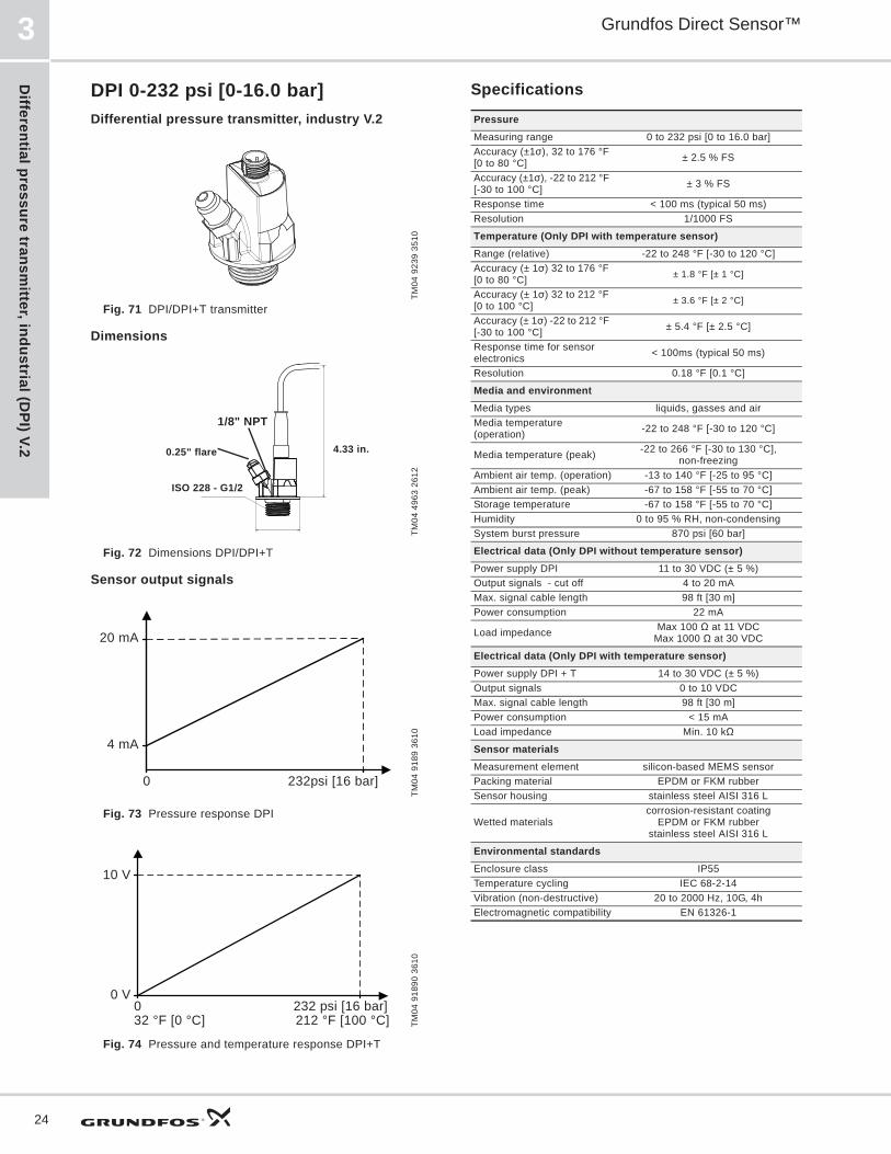
24
DPI 0-232 psi [0-16.0 bar]Differential pressure transmitter, industry V.2
Fig. 71 DPI/DPI+T transmitter
Dimensions
Fig. 72 Dimensions DPI/DPI+T
Sensor output signals
Fig. 73 Pressure response DPI
Fig. 74 Pressure and temperature response DPI+T
Specifications
TM04
923
9 35
10TM
04 4
963
2612
TM04
918
9 36
10TM
04 9
1890
361
0
4.33 in.
1/8" NPT
0.25" flare
ISO 228 - G1/2
0 232psi [16 bar]
20 mA
4 mA
0 232 psi [16 bar]
10 V
32 °F [0 °C] 212 °F [100 °C]
0 V
PressureMeasuring range 0 to 232 psi [0 to 16.0 bar]Accuracy (±1 ), 32 to 176 °F [0 to 80 °C] ± 2.5 % FS
Accuracy (±1 ), -22 to 212 °F [-30 to 100 °C] ± 3 % FS
Response time < 100 ms (typical 50 ms)Resolution 1/1000 FS
Temperature (Only DPI with temperature sensor)Range (relative) -22 to 248 °F [-30 to 120 °C]Accuracy (± 1 ) 32 to 176 °F [0 to 80 °C] ± 1.8 °F [± 1 °C]
Accuracy (± 1 ) 32 to 212 °F [0 to 100 °C] ± 3.6 °F [± 2 °C]
Accuracy (± 1 ) -22 to 212 °F [-30 to 100 °C] ± 5.4 °F [± 2.5 °C]
Response time for sensor electronics < 100ms (typical 50 ms)
Resolution 0.18 °F [0.1 °C]
Media and environmentMedia types liquids, gasses and airMedia temperature (operation) -22 to 248 °F [-30 to 120 °C]
Media temperature (peak) -22 to 266 °F [-30 to 130 °C], non-freezing
Ambient air temp. (operation) -13 to 140 °F [-25 to 95 °C]Ambient air temp. (peak) -67 to 158 °F [-55 to 70 °C]Storage temperature -67 to 158 °F [-55 to 70 °C]Humidity 0 to 95 % RH, non-condensingSystem burst pressure 870 psi [60 bar]
Electrical data (Only DPI without temperature sensor)Power supply DPI 11 to 30 VDC (± 5 %)Output signals - cut off 4 to 20 mA Max. signal cable length 98 ft [30 m]Power consumption 22 mA
Load impedance Max 100 at 11 VDCMax 1000 at 30 VDC
Electrical data (Only DPI with temperature sensor)Power supply DPI + T 14 to 30 VDC (± 5 %)Output signals 0 to 10 VDC Max. signal cable length 98 ft [30 m]Power consumption < 15 mALoad impedance Min. 10 k
Sensor materialsMeasurement element silicon-based MEMS sensorPacking material EPDM or FKM rubberSensor housing stainless steel AISI 316 L
Wetted materialscorrosion-resistant coating
EPDM or FKM rubberstainless steel AISI 316 L
Environmental standardsEnclosure class IP55Temperature cycling IEC 68-2-14Vibration (non-destructive) 20 to 2000 Hz, 10G, 4hElectromagnetic compatibility EN 61326-1
Diff
eren
tial p
ress
ure
tran
smitt
er, i
ndus
tria
l (D
PI)
Grundfos Direct Sensor™ 4
25
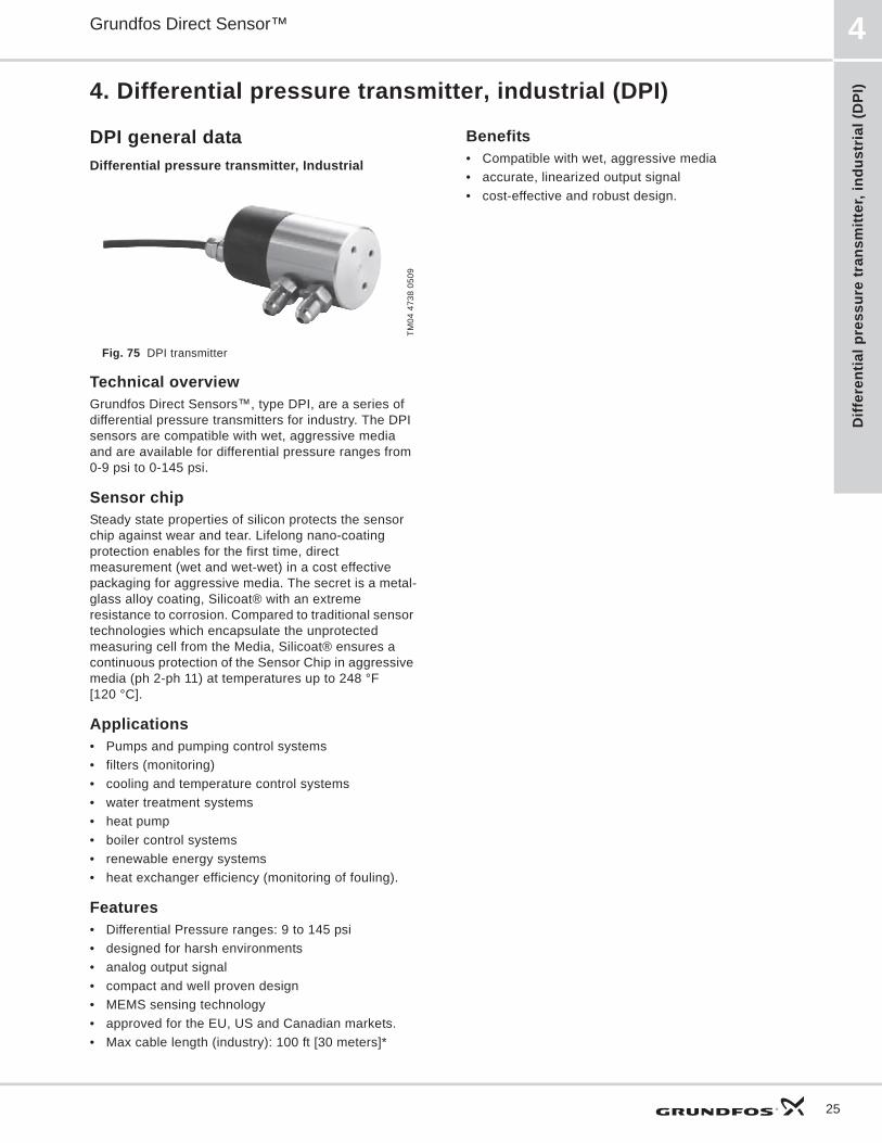
4. Differential pressure transmitter, industrial (DPI)
DPI general data Differential pressure transmitter, Industrial
Fig. 75 DPI transmitter
Technical overview Grundfos Direct Sensors , type DPI, are a series of differential pressure transmitters for industry. The DPI sensors are compatible with wet, aggressive media and are available for differential pressure ranges from 0-9 psi to 0-145 psi.
Sensor chipSteady state properties of silicon protects the sensor chip against wear and tear. Lifelong nano-coating protection enables for the first time, direct measurement (wet and wet-wet) in a cost effective packaging for aggressive media. The secret is a metal-glass alloy coating, Silicoat® with an extreme resistance to corrosion. Compared to traditional sensor technologies which encapsulate the unprotected measuring cell from the Media, Silicoat® ensures a continuous protection of the Sensor Chip in aggressive media (ph 2-ph 11) at temperatures up to 248 °F [120 °C].
Applications• Pumps and pumping control systems• filters (monitoring)• cooling and temperature control systems• water treatment systems• heat pump• boiler control systems• renewable energy systems• heat exchanger efficiency (monitoring of fouling).
Features• Differential Pressure ranges: 9 to 145 psi• designed for harsh environments• analog output signal• compact and well proven design• MEMS sensing technology• approved for the EU, US and Canadian markets.• Max cable length (industry): 100 ft [30 meters]*
Benefits• Compatible with wet, aggressive media• accurate, linearized output signal• cost-effective and robust design.
TM04
473
8 05
09
Differential pressure transm
itter, industrial (DPI)
Grundfos Direct Sensor™4
26
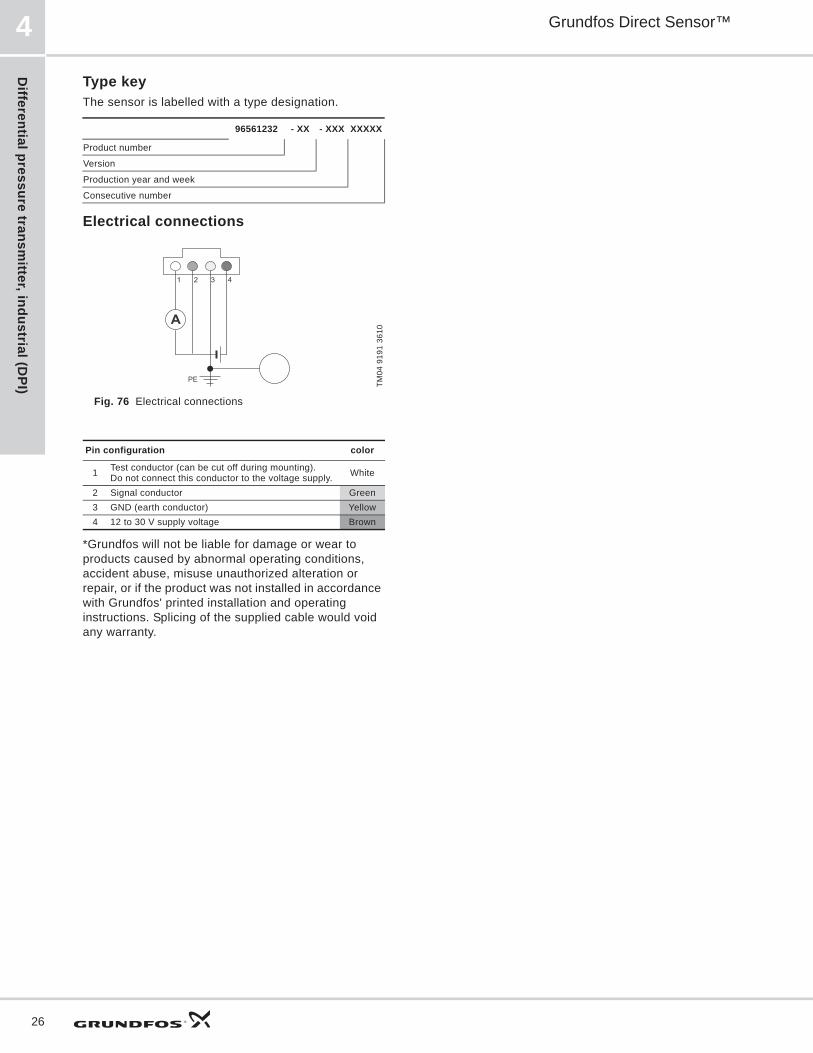
Type keyThe sensor is labelled with a type designation.
Electrical connections
Fig. 76 Electrical connections
*Grundfos will not be liable for damage or wear to products caused by abnormal operating conditions, accident abuse, misuse unauthorized alteration or repair, or if the product was not installed in accordance with Grundfos' printed installation and operating instructions. Splicing of the supplied cable would void any warranty.
96561232 - XX - XXX XXXXX
Product number
Version
Production year and week
Consecutive number
TM04
919
1 36
10
Pin configuration color
1 Test conductor (can be cut off during mounting).Do not connect this conductor to the voltage supply. White
2 Signal conductor Green3 GND (earth conductor) Yellow4 12 to 30 V supply voltage Brown
A
4321
PE

Diff
eren
tial p
ress
ure
tran
smitt
er, i
ndus
tria
l (D
PI)
Grundfos Direct Sensor™ 4
27
DPI 0-9 psi [0-0.6 bar]Differential pressure transmitter, industry
Fig. 77 DPI transmitter
Dimension
Fig. 78 Dimensions DPI transmitter
Output signals
Fig. 79 Differential pressure response
Specifications
TM04
503
4 24
09TM
03 2
059
1612
TM04
918
9 36
10
P2
P1
SW14
1/8" flare
0.55 in. [14 mm]
1.77 in. [45 mm]
0.24 in. [6 mm]
3.03 in. [77 mm]
0 9 psi [0.6 bar]
20 mA
4 mA
PressureMeasuring range (differential) 0 to 9 psi [0 to 0.6 bar]Accuracy (IEC 61298-2) 3.5 % FSResponse time < 0.5 sStatic Pressure P1 232 psi [16.0 bar]Static Pressure P2 145 psi [10.0 bar]Max system pressure 232 psi [16.0 bar]
Media and environmentMedia Liquids, gases and airMedia temperature (operation) 14 to 158 °F [-18 to 106 °C]Media temperature (peak) up to 176 °F [80 °C]Ambient air temperature -40 to 158 °F [-40 to 106 °C]Ambient air temperature (peak) -67 to 194 °F [-55 to 90 °C]
Humidity 0 to 95 % (relative), non-condensingSystem burst pressure 360 psi [25.0 bar]
Electrical dataPower supply 12 to 30 VDC Output signals 4 to 20 mA
Load impedance24 V max. 500 k16 V max. 200 k12 V max. 100 k
Sensor materialsSensing element Silicon-based MEMS sensor Seal FKM rubberHousing AISI 303 stainless steelWetted materials FKM and PPS
Environmental standardsEnclosure class IP55Temperature cycling IEC 68-2-14Vibration (non-destructive) 20 to 2000 Hz, 10G, 4hImmunity EN 61000-6-2Emission EN 61000-6-3Weight 1.2 lbs

Differential pressure transm
itter, industrial (DPI)
Grundfos Direct Sensor™4
28
DPI 0-14.5 psi [0-1.0 bar]Differential pressure transmitter, industry
Fig. 80 DPI transmitter
Dimension
Fig. 81 Dimensions DPI transmitter
Output signals
Fig. 82 Differential pressure response
Specifications
TM04
503
4 24
09TM
03 2
059
1612
TM04
918
9 36
10
P2
P1
SW14
1/8" flare
0.55 in. [14 mm]
1.77 in. [45 mm]
0.24 in. [6 mm]
3.03 in. [77 mm]
0 14.5 psi [1.0 bar]
20 mA
4 mA
PressureMeasuring range (differential) 0 to 14.5 psi [0 to 1.0 bar]Accuracy (IEC 61298-2) 2 % FSResponse time < 0.5 sStatic Pressure P1 232 psi [16.0 bar]Static Pressure P2 145 psi [10.0 bar]Max system pressure 232 psi [16.0 bar]
Media and environmentMedia Liquids, gasses and airMedia temperature (operation) 14 to 158 °F [-18 to 106 °C]Media temperature (peak) up to 176 °F [80 °C]Ambient air temperature -40 to 158 °F [-40 to 106 °C]Ambient air temperature (peak) -67 to 194 °F [-55 to 90 °C]
Humidity 0 to 95 % (relative), non-condensingSystem burst pressure 360 psi [25.0 bar]
Electrical dataPower supply 12-30 VDC Output signals 4-20 mA
Load impedance24 V max. 500 k16 V max. 200 k12 V max. 100 k
Sensor materialsSensing element Silicon-based MEMS sensor Seal FKM rubberHousing AISI 303 stainless steelWetted materials FKM and PPS
Environmental standardsEnclosure class IP55Temperature cycling IEC 68-2-14Vibration (non-destructive) 20 to 2000 Hz, 10G, 4hImmunity EN 61000-6-2Emission EN 61000-6-3Weight 1.2 lbs
Diff
eren
tial p
ress
ure
tran
smitt
er, i
ndus
tria
l (D
PI)
Grundfos Direct Sensor™ 4
29
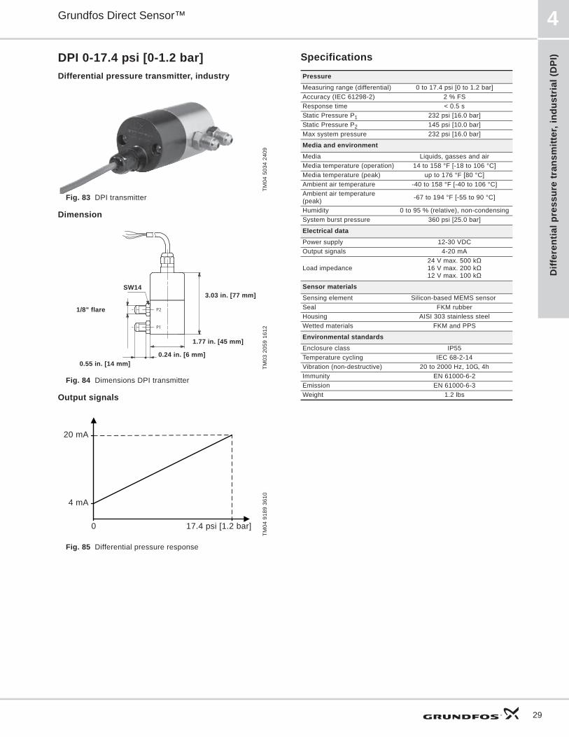
DPI 0-17.4 psi [0-1.2 bar]Differential pressure transmitter, industry
Fig. 83 DPI transmitter
Dimension
Fig. 84 Dimensions DPI transmitter
Output signals
Fig. 85 Differential pressure response
Specifications
TM04
503
4 24
09TM
03 2
059
1612
TM04
918
9 36
10
P2
P1
SW14
1/8" flare
0.55 in. [14 mm]
1.77 in. [45 mm]
0.24 in. [6 mm]
3.03 in. [77 mm]
0 17.4 psi [1.2 bar]
20 mA
4 mA
PressureMeasuring range (differential) 0 to 17.4 psi [0 to 1.2 bar]Accuracy (IEC 61298-2) 2 % FSResponse time < 0.5 sStatic Pressure P1 232 psi [16.0 bar]Static Pressure P2 145 psi [10.0 bar]Max system pressure 232 psi [16.0 bar]
Media and environmentMedia Liquids, gasses and airMedia temperature (operation) 14 to 158 °F [-18 to 106 °C]Media temperature (peak) up to 176 °F [80 °C]Ambient air temperature -40 to 158 °F [-40 to 106 °C]Ambient air temperature (peak) -67 to 194 °F [-55 to 90 °C]
Humidity 0 to 95 % (relative), non-condensingSystem burst pressure 360 psi [25.0 bar]
Electrical dataPower supply 12-30 VDC Output signals 4-20 mA
Load impedance24 V max. 500 k16 V max. 200 k12 V max. 100 k
Sensor materialsSensing element Silicon-based MEMS sensor Seal FKM rubberHousing AISI 303 stainless steelWetted materials FKM and PPS
Environmental standardsEnclosure class IP55Temperature cycling IEC 68-2-14Vibration (non-destructive) 20 to 2000 Hz, 10G, 4hImmunity EN 61000-6-2Emission EN 61000-6-3Weight 1.2 lbs
Differential pressure transm
itter, industrial (DPI)
Grundfos Direct Sensor™4
30
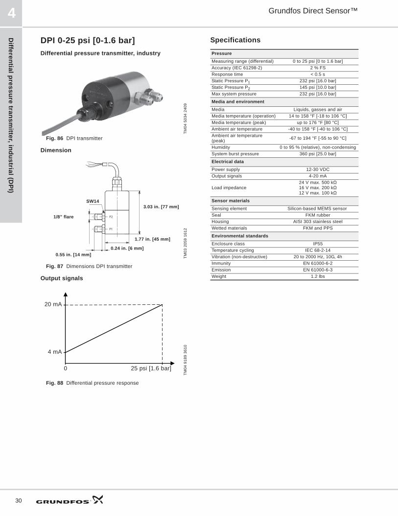
DPI 0-25 psi [0-1.6 bar]Differential pressure transmitter, industry
Fig. 86 DPI transmitter
Dimension
Fig. 87 Dimensions DPI transmitter
Output signals
Fig. 88 Differential pressure response
Specifications
TM04
503
4 24
09TM
03 2
059
1612
TM04
918
9 36
10
P2
P1
SW14
1/8" flare
0.55 in. [14 mm]
1.77 in. [45 mm]
0.24 in. [6 mm]
3.03 in. [77 mm]
0 25 psi [1.6 bar]
20 mA
4 mA
PressureMeasuring range (differential) 0 to 25 psi [0 to 1.6 bar]Accuracy (IEC 61298-2) 2 % FSResponse time < 0.5 sStatic Pressure P1 232 psi [16.0 bar]Static Pressure P2 145 psi [10.0 bar]Max system pressure 232 psi [16.0 bar]
Media and environmentMedia Liquids, gasses and airMedia temperature (operation) 14 to 158 °F [-18 to 106 °C]Media temperature (peak) up to 176 °F [80 °C]Ambient air temperature -40 to 158 °F [-40 to 106 °C]Ambient air temperature (peak) -67 to 194 °F [-55 to 90 °C]
Humidity 0 to 95 % (relative), non-condensingSystem burst pressure 360 psi [25.0 bar]
Electrical dataPower supply 12-30 VDC Output signals 4-20 mA
Load impedance24 V max. 500 k16 V max. 200 k12 V max. 100 k
Sensor materialsSensing element Silicon-based MEMS sensor Seal FKM rubberHousing AISI 303 stainless steelWetted materials FKM and PPS
Environmental standardsEnclosure class IP55Temperature cycling IEC 68-2-14Vibration (non-destructive) 20 to 2000 Hz, 10G, 4hImmunity EN 61000-6-2Emission EN 61000-6-3Weight 1.2 lbs
Diff
eren
tial p
ress
ure
tran
smitt
er, i
ndus
tria
l (D
PI)
Grundfos Direct Sensor™ 4
31
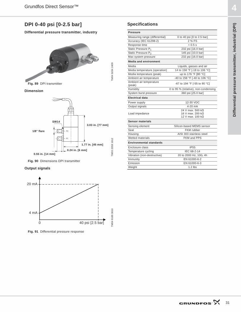
DPI 0-40 psi [0-2.5 bar]Differential pressure transmitter, industry
Fig. 89 DPI transmitter
Dimension
Fig. 90 Dimensions DPI transmitter
Output signals
Fig. 91 Differential pressure response
Specifications
TM04
503
4 24
09TM
03 2
059
1612
TM04
918
9 36
10
P2
P1
SW14
1/8" flare
0.55 in. [14 mm]
1.77 in. [45 mm]
0.24 in. [6 mm]
3.03 in. [77 mm]
0 40 psi [2.5 bar]
20 mA
4 mA
PressureMeasuring range (differential) 0 to 40 psi [0 to 2.5 bar]Accuracy (IEC 61298-2) 2 % FSResponse time < 0.5 sStatic Pressure P1 232 psi [16.0 bar]Static Pressure P2 145 psi [10.0 bar]Max system pressure 232 psi [16.0 bar]
Media and environmentMedia Liquids, gasses and airMedia temperature (operation) 14 to 158 °F [-18 to 106 °C]Media temperature (peak) up to 176 °F [80 °C]Ambient air temperature -40 to 158 °F [-40 to 106 °C]Ambient air temperature (peak) -67 to 194 °F [-55 to 90 °C]
Humidity 0 to 95 % (relative), non-condensingSystem burst pressure 360 psi [25.0 bar]
Electrical dataPower supply 12-30 VDC Output signals 4-20 mA
Load impedance24 V max. 500 k16 V max. 200 k12 V max. 100 k
Sensor materialsSensing element Silicon-based MEMS sensor Seal FKM rubberHousing AISI 303 stainless steelWetted materials FKM and PPS
Environmental standardsEnclosure class IP55Temperature cycling IEC 68-2-14Vibration (non-destructive) 20 to 2000 Hz, 10G, 4hImmunity EN 61000-6-2Emission EN 61000-6-3Weight 1.2 lbs

Differential pressure transm
itter, industrial (DPI)
Grundfos Direct Sensor™4
32
DPI 0-60 psi [0-4.0 bar]Differential pressure transmitter, industry
Fig. 92 DPI transmitter 0 to 60 psi
Dimension
Fig. 93 Dimensions DPI transmitter
Output signals
Fig. 94 Differential pressure response
Specifications
TM04
503
4 24
09TM
03 2
059
1612
TM04
918
9 36
10
P2
P1
SW14
1/8" flare
0.55 in. [14 mm]
1.77 in. [45 mm]
0.24 in. [6 mm]
3.03 in. [77 mm]
0 60 psi [4.0 bar]
20 mA
4 mA
PressureMeasuring range (differential) 0 to 60 psi [0 to 4.0 bar]Accuracy (IEC 61298-2) 2 % FSResponse time < 0.5 sStatic Pressure P1 232 psi [16.0 bar]Static Pressure P2 145 psi [10.0 bar]Max system pressure 232 psi [16.0 bar]
Media and environmentMedia Liquids, gasses and airMedia temperature (operation) 14 to 158 °F [-18 to 106 °C]Media temperature (peak) up to 176 °F [80 °C]Ambient air temperature -40 to 158 °F [-40 to 106 °C]Ambient air temperature (peak) -67 to 194 °F [-55 to 90 °C]
Humidity 0 to 95 % (relative), non-condensingSystem burst pressure 360 psi [25.0 bar]
Electrical dataPower supply 12-30 VDC Output signals 4-20 mA
Load impedance24 V max. 500 k16 V max. 200 k12 V max. 100 k
Sensor materialsSensing element Silicon-based MEMS sensor Seal FKM rubberHousing AISI 303 stainless steelWetted materials FKM and PPS
Environmental standardsEnclosure class IP55Temperature cycling IEC 68-2-14Vibration (non-destructive) 20 to 2000 Hz, 10G, 4hImmunity EN 61000-6-2Emission EN 61000-6-3Weight 1.2 lbs
Diff
eren
tial p
ress
ure
tran
smitt
er, i
ndus
tria
l (D
PI)
Grundfos Direct Sensor™ 4
33
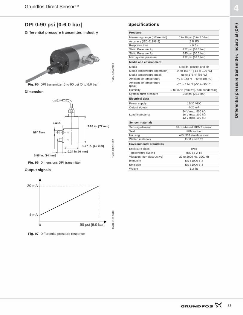
DPI 0-90 psi [0-6.0 bar]Differential pressure transmitter, industry
Fig. 95 DPI transmitter 0 to 90 psi [0 to 6.0 bar]
Dimension
Fig. 96 Dimensions DPI transmitter
Output signals
Fig. 97 Differential pressure response
Specifications
TM04
503
4 24
09TM
03 2
059
1612
TM04
918
9 36
10
P2
P1
SW14
1/8" flare
0.55 in. [14 mm]
1.77 in. [45 mm]
0.24 in. [6 mm]
3.03 in. [77 mm]
0 90 psi [6.0 bar]
20 mA
4 mA
PressureMeasuring range (differential) 0 to 90 psi [0 to 6.0 bar]Accuracy (IEC 61298-2) 2 % FSResponse time < 0.5 sStatic Pressure P1 232 psi [16.0 bar]Static Pressure P2 145 psi [10.0 bar]Max system pressure 232 psi [16.0 bar]
Media and environmentMedia Liquids, gasses and airMedia temperature (operation) 14 to 158 °F [-18 to 106 °C]Media temperature (peak) up to 176 °F [80 °C]Ambient air temperature -40 to 158 °F [-40 to 106 °C]Ambient air temperature (peak) -67 to 194 °F [-55 to 90 °C]
Humidity 0 to 95 % (relative), non-condensingSystem burst pressure 360 psi [25.0 bar]
Electrical dataPower supply 12-30 VDC Output signals 4-20 mA
Load impedance24 V max. 500 k16 V max. 200 k12 V max. 100 k
Sensor materialsSensing element Silicon-based MEMS sensor Seal FKM rubberHousing AISI 303 stainless steelWetted materials FKM and PPS
Environmental standardsEnclosure class IP55Temperature cycling IEC 68-2-14Vibration (non-destructive) 20 to 2000 Hz, 10G, 4hImmunity EN 61000-6-2Emission EN 61000-6-3Weight 1.2 lbs

Differential pressure transm
itter, industrial (DPI)
Grundfos Direct Sensor™4
34
DPI 0-145 psi [0-10.0 bar]Differential pressure transmitter, industry
Fig. 98 DPI transmitter 0 to 145 psi
Dimension
Fig. 99 Dimensions DPI transmitter
Output signals
Fig. 100 Differential pressure response
Specifications
TM04
503
4 24
09TM
03 2
059
1612
TM04
918
9 36
10
P2
P1
SW14
1/8" flare
0.55 in. [14 mm]
1.77 in. [45 mm]
0.24 in. [6 mm]
3.03 in. [77 mm]
0 145 psi [10 bar]
20 mA
4 mA
PressureMeasuring range (differential) 0 to 145 psi [0 to 10 bar]Accuracy (IEC 61298-2) 2 % FSResponse time < 0.5 sStatic Pressure P1 232 psi [16.0 bar]Static Pressure P2 145 psi [10.0 bar]Max system pressure 232 psi [16.0 bar]
Media and environmentMedia Liquids, gasses and airMedia temperature (operation) 14 to 158 °F [-18 to 106 °C]Media temperature (peak) up to 176 °F [80 °C] Ambient air temperature -40 to 158 °F [-40 to 106 °C]Ambient air temperature (peak) -67 to 194 °F [-55 to 90 °C]
Humidity 0 to 95 % (relative), non-condensingSystem burst pressure 360 psi [25.0 bar]
Electrical dataPower supply 12-30 VDC Output signals 4-20 mA
Load impedance24 V max. 500 k16 V max. 200 k12 V max. 100 k
Sensor materialsSensing element Silicon-based MEMS sensor Seal FKM rubberHousing AISI 303 stainless steelWetted materials FKM and PPS
Environmental standardsEnclosure class IP55Temperature cycling IEC 68-2-14Vibration (non-destructive) 20 to 2000 Hz, 10G, 4hImmunity EN 61000-6-2Emission EN 61000-6-3Weight 1.2 lbs
Rel
ativ
e pr
essu
re s
enso
r st
anda
rd (R
PS)
Grundfos Direct Sensor™ 5
35
5. Relative pressure sensor standard (RPS)
RPS general dataRelative pressure sensor, standard
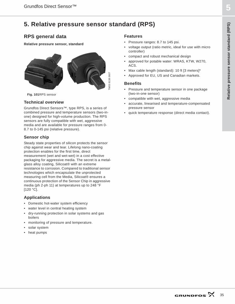
Fig. 101RPS sensor
Technical overviewGrundfos Direct Sensors™, type RPS, is a series of combined pressure and temperature sensors (two-in-one) designed for high-volume production. The RPS sensors are fully compatible with wet, aggressive media and are available for pressure ranges from 0-8.7 to 0-145 psi (relative pressure).
Sensor chipSteady state properties of silicon protects the sensor chip against wear and tear. Lifelong nano-coating protection enables for the first time, direct measurement (wet and wet-wet) in a cost effective packaging for aggressive media. The secret is a metal-glass alloy coating, Silicoat® with an extreme resistance to corrosion. Compared to traditional sensor technologies which encapsulate the unprotected measuring cell from the Media, Silicoat® ensures a continuous protection of the Sensor Chip in aggressive media (ph 2-ph 11) at temperatures up to 248 °F [120 °C].
Applications• Domestic hot-water system efficiency • water level in central heating system• dry-running protection in solar systems and gas
boilers• monitoring of pressure and temperature.• solar system• heat pumps
Features• Pressure ranges: 8.7 to 145 psi.• voltage output (ratio metric, ideal for use with micro
controller) • compact and robust mechanical design• approved for potable water: WRAS, KTW, W270,
ACS.• Max cable length (standard): 10 ft [3 meters]*• Approved for EU, US and Canadian markets.
Benefits• Pressure and temperature sensor in one package
(two-in-one sensor) • compatible with wet, aggressive media• accurate, linearised and temperature-compensated
pressure sensor• quick temperature response (direct media contact).
TM03
813
8 06
07
Relative pressure sensor standard (R
PS)
Grundfos Direct Sensor™5
36
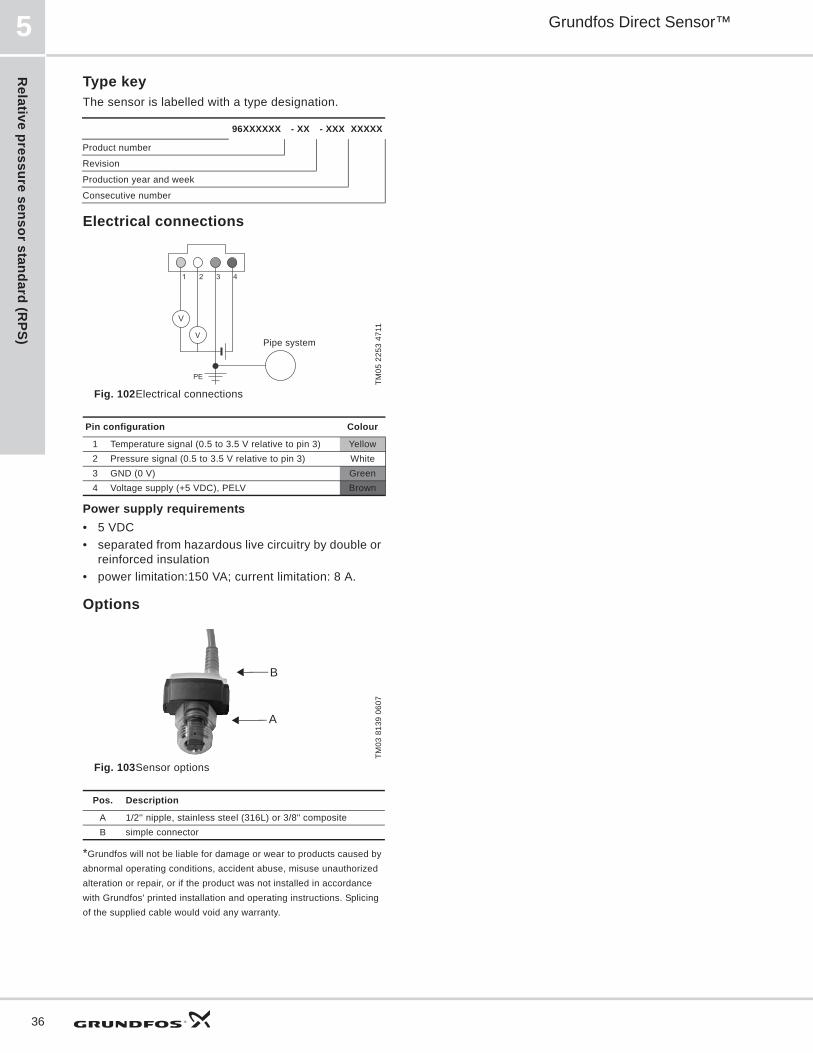
Type keyThe sensor is labelled with a type designation.
Electrical connections
Fig. 102Electrical connections
Power supply requirements• 5 VDC• separated from hazardous live circuitry by double or
reinforced insulation• power limitation:150 VA; current limitation: 8 A.
Options
Fig. 103Sensor options
*Grundfos will not be liable for damage or wear to products caused by abnormal operating conditions, accident abuse, misuse unauthorized alteration or repair, or if the product was not installed in accordance with Grundfos' printed installation and operating instructions. Splicing of the supplied cable would void any warranty.
96XXXXXX - XX - XXX XXXXX
Product number
Revision
Production year and week
Consecutive number
TM05
225
3 47
11
Pin configuration Colour
1 Temperature signal (0.5 to 3.5 V relative to pin 3) Yellow2 Pressure signal (0.5 to 3.5 V relative to pin 3) White3 GND (0 V) Green4 Voltage supply (+5 VDC), PELV Brown
TM03
813
9 06
07
Pos. Description
A 1/2'' nipple, stainless steel (316L) or 3/8" compositeB simple connector
V
V
4321
PE
Pipe system
A
B
Rel
ativ
e pr
essu
re s
enso
r st
anda
rd (R
PS)
Grundfos Direct Sensor™ 5
37
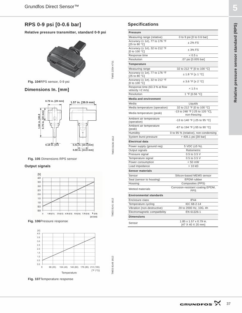
RPS 0-9 psi [0-0.6 bar]Relative pressure transmitter, standard 0-9 psi
Fig. 104RPS sensor, 0-9 psi
Dimensions In. [mm]
Fig. 105 Dimensions RPS sensor
Output signals
Fig. 106Pressure response
Fig. 107Temperature response
Specifications
TM05
225
4 47
11TM
03 8
136
1612
TM03
814
1 16
12TM
03 8
149
1612
0.79
in. [
20 m
m]
1.84
in. [
46.8
0.79 in. [20 mm]
0.18 in. [4.5
1.57 in. [39.9 mm]
0.41 in. [10.3 mm]
0.59 in. [14.9 mm]
[V]
PressureMeasuring range (relative) 0 to 9 psi [0 to 0.6 bar]Accuracy (± 1 ), 77 to 176 °F [25 to 80 °C] ± 2% FS
Accuracy (± 1 ), 32 to 212 °F [0 to 100 °C] ± 3% FS
Response time < 0.5 sResolution .07 psi [0.005 bar]
TemperatureMeasuring range 32 to 212 °F [0 to 100 °C]Accuracy (± 1 ), 77 to 176 °F [25 to 80 °C] ± 1.8 °F [± 1 °C]
Accuracy (± 1 ), 32 to 212 °F [0 to 100 °C] ± 3.6 °F [± 2 °C]
Response time (63.3 % at flow velocity >2 m/s) < 1.5 s
Resolution 1 °F [0.56 °C]
Media and environmentMedia LiquidsMedia temperature (operation) 32 to 212 °F [0 to 100 °C]
Media temperature (peak) -13 to 248 °F [-25 to 120 °C], non-freezing
Ambient air temperature (operation) -13 to 140 °F [-25 to 95 °C]
Ambient air temperature (peak) -67 to 194 °F [-55 to 90 °C]
Humidity 0 to 95 % (relative), non-condensingSystem burst pressure > 435.1 psi [30 bar]
Electrical dataPower supply (ground req) 5 VDC (±5 %). Output signals RatiometricPressure signal 0.5 to 3.5 VTemperature signal 0.5 to 3.5 VPower consumption < 50 mWLoad impedance > 10 k
Sensor materialsSensor Silicon-based MEMS sensor Seal (sensor to housing) EPDM rubberHousing Composites (PPS)
Wetted materials Corrosion-resistant coating EPDM, PPS
Environmental standardsEnclosure class IP44Temperature cycling IEC 68-2-14Vibration (non-destructive) 20 to 2000 Hz, 10G, 4hElectromagnetic compatibility EN 61326-1
Dimensions
Sensor 1.85 x 1.57 x 0.79 in. [47 X 40 X 20 mm]
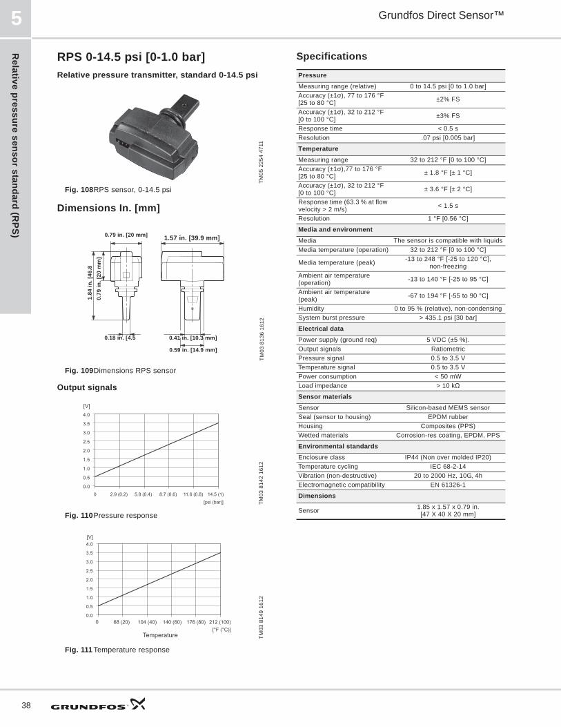
Relative pressure sensor standard (R
PS)
Grundfos Direct Sensor™5
38
RPS 0-14.5 psi [0-1.0 bar]Relative pressure transmitter, standard 0-14.5 psi
Fig. 108RPS sensor, 0-14.5 psi
Dimensions In. [mm]
Fig. 109Dimensions RPS sensor
Output signals
Fig. 110Pressure response
Fig. 111 Temperature response
Specifications
TM05
225
4 47
11TM
03 8
136
1612
TM03
814
2 16
12TM
03 8
149
1612
0.79
in. [
20 m
m]
1.84
in. [
46.8
0.79 in. [20 mm]
0.18 in. [4.5
1.57 in. [39.9 mm]
0.41 in. [10.3 mm]
0.59 in. [14.9 mm]
[V]
PressureMeasuring range (relative) 0 to 14.5 psi [0 to 1.0 bar]Accuracy (±1 ), 77 to 176 °F [25 to 80 °C] ±2% FS
Accuracy (±1 ), 32 to 212 °F [0 to 100 °C] ±3% FS
Response time < 0.5 sResolution .07 psi [0.005 bar]
TemperatureMeasuring range 32 to 212 °F [0 to 100 °C]Accuracy (±1 ),77 to 176 °F [25 to 80 °C] ± 1.8 °F [± 1 °C]
Accuracy (±1 ), 32 to 212 °F [0 to 100 °C] ± 3.6 °F [± 2 °C]
Response time (63.3 % at flow velocity > 2 m/s) < 1.5 s
Resolution 1 °F [0.56 °C]
Media and environmentMedia The sensor is compatible with liquidsMedia temperature (operation) 32 to 212 °F [0 to 100 °C]
Media temperature (peak) -13 to 248 °F [-25 to 120 °C], non-freezing
Ambient air temperature (operation) -13 to 140 °F [-25 to 95 °C]
Ambient air temperature (peak) -67 to 194 °F [-55 to 90 °C]
Humidity 0 to 95 % (relative), non-condensingSystem burst pressure > 435.1 psi [30 bar]
Electrical dataPower supply (ground req) 5 VDC (±5 %).Output signals RatiometricPressure signal 0.5 to 3.5 VTemperature signal 0.5 to 3.5 VPower consumption < 50 mWLoad impedance > 10 k
Sensor materialsSensor Silicon-based MEMS sensor Seal (sensor to housing) EPDM rubberHousing Composites (PPS)Wetted materials Corrosion-res coating, EPDM, PPS
Environmental standardsEnclosure class IP44 (Non over molded IP20)Temperature cycling IEC 68-2-14Vibration (non-destructive) 20 to 2000 Hz, 10G, 4hElectromagnetic compatibility EN 61326-1
Dimensions
Sensor 1.85 x 1.57 x 0.79 in. [47 X 40 X 20 mm]

Rel
ativ
e pr
essu
re s
enso
r st
anda
rd (R
PS)
Grundfos Direct Sensor™ 5
39
RPS 0-25 psi [0-1.6 bar]Relative pressure transmitter, standard 0-25 psi
Fig. 112RPS sensor, 0-25 psi
Dimensions In. [mm]
Fig. 113 Dimensions RPS sensor
Output signals
Fig. 114Pressure response
Fig. 115 Temperature response
Specifications
TM05
225
4 47
11TM
03 8
136
1612
TM03
814
3 16
12TM
03 8
149
1612
0.79
in. [
20 m
m]
1.84
in. [
46.8
0.79 in. [20 mm]
0.18 in. [4.5
1.57 in. [39.9 mm]
0.41 in. [10.3 mm]
0.59 in. [14.9 mm]
[V]
PressureMeasuring range (relative) 0 to 25 psi [0 to 1.6 bar]Accuracy (±1 ), 77 to 176 °F [25 to 80 °C] ±1.5 % FS
Accuracy (±1 ), 32 to 212 °F [0 to 100 °C] ±2.5 % FS
Response time < 0.5 sResolution .07 psi [0.005 bar]
TemperatureMeasuring range 32 to 212 °F [0 to 100 °C]Accuracy (±1 ), 77 to 176 °F [25 to 80 °C] ± 1.8 °F [± 1 °C]
Accuracy (±1 ), 32 to 212 °F [0 to 100 °C] ± 3.6 °F [± 2 °C]
Response time (63.3 % at flow velocity > 2 m/s) < 1.5 s
Resolution 1 °F [0.56 °C]
Media and environment
Media The sensor is compatible with liquids
Media temperature (operation) 32 to 212 °F [0 to 100 °C]
Media temperature (peak) -13 to 248 °F [-25 to 120 °C], non-freezing
Ambient air temperature (operation) -13 to 140 °F [-25 to 95 °C]
Ambient air temperature (peak) -67 to 194 °F [-55 to 90 °C]Relative humidity 0 to 95 %, non-condensingSystem burst pressure > 435.1 psi [30 bar]
Electrical interfacePower supply (ground req) 5 VDC (±5 %).Output signals RatiometricPressure signal 0.5 to 3.5 VTemperature signal 0.5 to 3.5 VPower consumption < 50 mWLoad impedance > 10 k
Sensor materialsSensor Silicon-based MEMS sensor Seal (sensor to housing) EPDM rubberHousing Composites (PPS)Wetted materials Corrosion-res coating, EPDM, PPS
Environmental standardsEnclosure class IP44Temperature cycling IEC 68-2-14Vibration (non-destructive) 20 to 2000 Hz, 10G, 4hElectromagnetic compatibility EN 61326-1
Dimensions
Sensor 1.85 x 1.57 x 0.79 in. [47 X 40 X 20 mm]
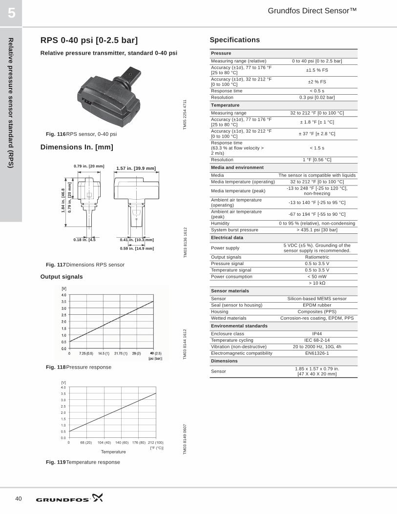
Relative pressure sensor standard (R
PS)
Grundfos Direct Sensor™5
40
RPS 0-40 psi [0-2.5 bar]Relative pressure transmitter, standard 0-40 psi
Fig. 116RPS sensor, 0-40 psi
Dimensions In. [mm]
Fig. 117Dimensions RPS sensor
Output signals
Fig. 118Pressure response
Fig. 119Temperature response
Specifications
TM05
225
4 47
11TM
03 8
136
1612
TM03
814
4 16
12TM
03 8
149
0607
0.79
in. [
20 m
m]
1.84
in. [
46.8
0.79 in. [20 mm]
0.18 in. [4.5
1.57 in. [39.9 mm]
0.41 in. [10.3 mm]
0.59 in. [14.9 mm]
[V]
PressureMeasuring range (relative) 0 to 40 psi [0 to 2.5 bar]Accuracy (±1 ), 77 to 176 °F [25 to 80 °C] ±1.5 % FS
Accuracy (±1 ), 32 to 212 °F [0 to 100 °C] ±2 % FS
Response time < 0.5 sResolution 0.3 psi [0.02 bar]
TemperatureMeasuring range 32 to 212 °F [0 to 100 °C]Accuracy (±1 ), 77 to 176 °F [25 to 80 °C] ± 1.8 °F [± 1 °C]
Accuracy (±1 ), 32 to 212 °F [0 to 100 °C] ± 37 °F [± 2.8 °C]
Response time (63.3 % at flow velocity > 2 m/s)
< 1.5 s
Resolution 1 °F [0.56 °C]
Media and environmentMedia The sensor is compatible with liquidsMedia temperature (operating) 32 to 212 °F [0 to 100 °C]
Media temperature (peak) -13 to 248 °F [-25 to 120 °C], non-freezing
Ambient air temperature (operating) -13 to 140 °F [-25 to 95 °C]
Ambient air temperature (peak) -67 to 194 °F [-55 to 90 °C]
Humidity 0 to 95 % (relative), non-condensingSystem burst pressure > 435.1 psi [30 bar]
Electrical data
Power supply 5 VDC (±5 %). Grounding of the sensor supply is recommended.
Output signals RatiometricPressure signal 0.5 to 3.5 VTemperature signal 0.5 to 3.5 VPower consumption < 50 mWLoad impedance > 10 k
Sensor materialsSensor Silicon-based MEMS sensor Seal (sensor to housing) EPDM rubberHousing Composites (PPS)Wetted materials Corrosion-res coating, EPDM, PPS
Environmental standardsEnclosure class IP44 Temperature cycling IEC 68-2-14Vibration (non-destructive) 20 to 2000 Hz, 10G, 4hElectromagnetic compatibility EN61326-1
Dimensions
Sensor 1.85 x 1.57 x 0.79 in. [47 X 40 X 20 mm]

Rel
ativ
e pr
essu
re s
enso
r st
anda
rd (R
PS)
Grundfos Direct Sensor™ 5
41
RPS 0-60 psi [0-4.0 bar]Relative pressure transmitter, standard 0-60 psi
Fig. 120RPS sensor, 0-60 psi
Dimensions In. [mm]
Fig. 121Dimensions RPS sensor
Output signals
Fig. 122Pressure response
Fig. 123Temperature response
Specifications
TM05
225
4 47
11TM
03 8
136
1612
TM03
814
5 16
12TM
03 8
149
1612
0.79
in. [
20 m
m]
1.84
in. [
46.8
0.79 in. [20 mm]
0.18 in. [4.5
1.57 in. [39.9 mm]
0.41 in. [10.3 mm]
0.59 in. [14.9 mm]
[V]
PressureMeasuring range (relative) 0 to 60 psi [0 to 4.0 bar]Accuracy (±1 ), 77 to 176 °F [25 to 80 °C] ±2 % FS
Accuracy (±1 ), 32 to 212 °F [0 to 100 °C] ±2.5 % FS
Response time < 0.5 sResolution 0.3 psi [0.02 bar]
TemperatureMeasuring range 32 to 212 °F [0 to 100 °C]Accuracy (±1 ), 77 to 176 °F [25 to 80 °C] ± 1.8 °F [± 1 °C]
Accuracy (±1 ), 32 to 212 °F [0 to 100 °C] ± 3.6 °F [± 2 °C]
Response time (63.3 % at flow velocity > 2 m/s) < 1.5 s
Resolution 1 °F [0.56 °C]
Media and environment
Media The sensor is compatible with liquids
Media temperature (operation) 32 to 212 °F [0 to 100 °C]
Media temperature (peak) -13 to 248 °F [-25 to 120 °C], non-freezing
Ambient air temperature (operation) -13 to 140 °F [-25 to 95 °C]
Ambient air temperature (peak) -67 to 194 °F [-55 to 90 °C]Humidity 0 to 95 % (relative), non-condensingSystem burst pressure > 435.1 psi [30 bar]
Electrical data
Power supply 5 VDC (±5 %). Grounding of the sensor supply is recommended.
Output signals RatiometricPressure signal 0.5 to 3.5 VTemperature signal 0.5 to 3.5 VPower consumption < 50 mWLoad impedance > 10 k
Sensor materialsSensor Silicon-based MEMS sensor Seal (sensor to housing) EPDM rubberHousing Composites (PPS)Wetted materials Corrosion-res coating, EPDM, PPS
Environmental standardsEnclosure class IP44 Temperature cycling IEC 68-2-14Vibration (non-destructive) 20 to 2000 Hz, 10G, 4hElectromagnetic compatibility EN 61326-1
Dimensions
Sensor 1.85 x 1.57 x 0.79 in. [47 X 40 X 20 mm]

Relative pressure sensor standard (R
PS)
Grundfos Direct Sensor™5
42
RPS 0-90 psi [0-6.0 bar]Relative pressure transmitter, standard 0-90 psi
Fig. 124RPS sensor, 0-90 psi
Dimensions In. [mm]
Fig. 125Dimensions RPS sensor
Output signals
Fig. 126Pressure response
Fig. 127Temperature response
Specifications
TM05
225
4 47
11TM
03 8
136
1612
TM03
814
6 16
12TM
03 8
149
0607
0.79
in. [
20 m
m]
1.84
in. [
46.8
0.79 in. [20 mm]
0.18 in. [4.5
1.57 in. [39.9 mm]
0.41 in. [10.3 mm]
0.59 in. [14.9 mm]
[V]
PressureMeasuring range (relative) 0 to 90 psi [0 to 6.0 bar]Accuracy (±1 ), 77 to 176 °F [25 to 80 °C] ±2% FS
Accuracy (±1 ), 32 to 212 °F [0 to 100 °C] ±2.5% FS
Response time < 0.5 sResolution 0.3 psi [0.02 bar]
TemperatureMeasuring range 32 to 212 °F [0 to 100 °C]Accuracy (±1 ), 77 to 176 °F [25 to 80 °C] ± 1.8 °F [± 1 °C]
Accuracy (±1 ), 32 to 212 °F [0 to 100 °C] ± 37 °F [± 2.8 °C]
Response time (63.3 % at flow velocity > 2 m/s) < 1.5 s
Resolution 1 °F [0.56 °C]
Media and environmentMedia The sensor is compatible with liquidsMedia temperature (operation) 32 to 212 °F [0 to 100 °C]
Media temperature (peak) -13 to 248 °F [-25 to 120 °C], non-freezing
Ambient air temperature (operation) -13 to 140 °F [-25 to 95 °C]
Ambient air temperature (peak) -67 to 194 °F [-55 to 90 °C]
Humidity 0 to 95 % (relative), non-condensingSystem burst pressure > 435.1 psi [30 bar]
Electrical data
Power supply 5 VDC (±5 %). Grounding of the sensor supply is recommended.
Output signals RatiometricPressure signal 0.5 to 3.5 VTemperature signal 0.5 to 3.5 VPower consumption < 50 mWLoad impedance > 10 k
Sensor materialsSensor Silicon-based MEMS sensor Seal (sensor to housing) EPDM rubberHousing Composites (PPS)
Wetted materials Corrosion-resistant coating EPDM, PPS
Environmental standardsEnclosure class IP44Temperature cycling IEC 68-2-14Vibration (non-destructive) 20 to 2000 Hz, 10G, 4hElectromagnetic compatibility EN 61326-1
Dimensions
Sensor 1.85 x 1.57 x 0.79 in. [47 X 40 X 20 mm]
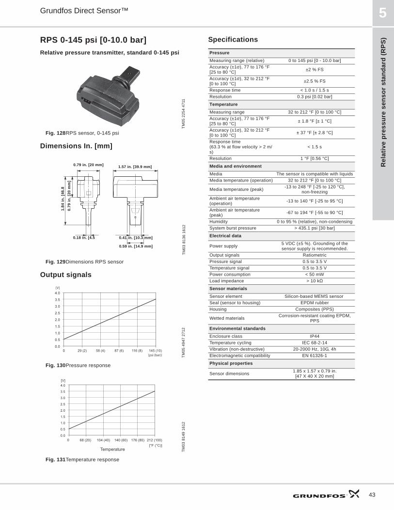
Rel
ativ
e pr
essu
re s
enso
r st
anda
rd (R
PS)
Grundfos Direct Sensor™ 5
43
RPS 0-145 psi [0-10.0 bar]Relative pressure transmitter, standard 0-145 psi
Fig. 128RPS sensor, 0-145 psi
Dimensions In. [mm]
Fig. 129Dimensions RPS sensor
Output signals
Fig. 130Pressure response
Fig. 131Temperature response
Specifications
TM05
225
4 47
11TM
03 8
136
1612
TM05
494
7 27
12TM
03 8
149
1612
0.79
in. [
20 m
m]
1.84
in. [
46.8
0.79 in. [20 mm]
0.18 in. [4.5
1.57 in. [39.9 mm]
0.41 in. [10.3 mm]
0.59 in. [14.9 mm]
[V]
PressureMeasuring range (relative) 0 to 145 psi [0 - 10.0 bar]Accuracy (±1 ), 77 to 176 °F [25 to 80 °C] ±2 % FS
Accuracy (±1 ), 32 to 212 °F [0 to 100 °C] ±2.5 % FS
Response time < 1.0 s / 1.5 sResolution 0.3 psi [0.02 bar]
TemperatureMeasuring range 32 to 212 °F [0 to 100 °C]Accuracy (±1 ), 77 to 176 °F [25 to 80 °C] ± 1.8 °F [± 1 °C]
Accuracy (±1 ), 32 to 212 °F [0 to 100 °C] ± 37 °F [± 2.8 °C]
Response time(63.3 % at flow velocity > 2 m/s)
< 1.5 s
Resolution 1 °F [0.56 °C]
Media and environmentMedia The sensor is compatible with liquidsMedia temperature (operation) 32 to 212 °F [0 to 100 °C]
Media temperature (peak) -13 to 248 °F [-25 to 120 °C], non-freezing
Ambient air temperature (operation) -13 to 140 °F [-25 to 95 °C]
Ambient air temperature (peak) -67 to 194 °F [-55 to 90 °C]
Humidity 0 to 95 % (relative), non-condensingSystem burst pressure > 435.1 psi [30 bar]
Electrical data
Power supply 5 VDC (±5 %). Grounding of the sensor supply is recommended.
Output signals RatiometricPressure signal 0.5 to 3.5 VTemperature signal 0.5 to 3.5 VPower consumption < 50 mWLoad impedance > 10 k
Sensor materialsSensor element Silicon-based MEMS sensor Seal (sensor to housing) EPDM rubberHousing Composites (PPS)
Wetted materials Corrosion-resistant coating EPDM, PPS
Environmental standardsEnclosure class IP44Temperature cycling IEC 68-2-14Vibration (non-destructive) 20-2000 Hz, 10G, 4hElectromagnetic compatibility EN 61326-1
Physical properties
Sensor dimensions 1.85 x 1.57 x 0.79 in. [47 X 40 X 20 mm]

Differential pressure sensor, standard (D
PS)
Grundfos Direct Sensor™6
44
6. Differential pressure sensor, standard (DPS)
DPS general data
Fig. 132DPS sensor
Technical overview Grundfos Direct Sensors , type DPS, is a series of combined differential-pressure and temperature sensors (two-in-one). The DPS sensors are fully compatible with wet, aggressive media.
Sensor chipSteady state properties of silicon protects the sensor chip against wear and tear. Lifelong nano-coating protection enables for the first time, direct measurement (wet and wet-wet) in a cost effective packaging for aggressive media. The secret is a metal-glass alloy coating, Silicoat® with an extreme resistance to corrosion. Compared to traditional sensor technologies which encapsulate the unprotected measuring cell from the Media, Silicoat® ensures a continuous protection of the Sensor Chip in aggressive media (ph 2-ph 11) at temperatures up to 248 °F [120 °C].
Applications• Pump and pump control systems• water treatment systems• filters (monitoring)• floor heating• heat pump• valve-controlled systems• cooling and temperature control systems• building management systems.
Features• Differential pressure ranges: 9 to 90 psi• high burst pressure• compact and robust mechanical design• voltage output (ratiometric, ideal for use with micro
controller) • approved for potable water: WRAS, KTW, ACS.• designed for harsh environments.• Max cable length (standard): 10 ft [3 meters]*• Approved for EU, US and Canadian markets
Benefits• Differential-pressure and temperature sensor in one
package (two-in-one sensor)• compatible with wet, aggressive media• accurate, linearized and temperature-compensated
differential-pressure transmitter• quick temperature response (direct media contact).
TM04
445
7 13
09
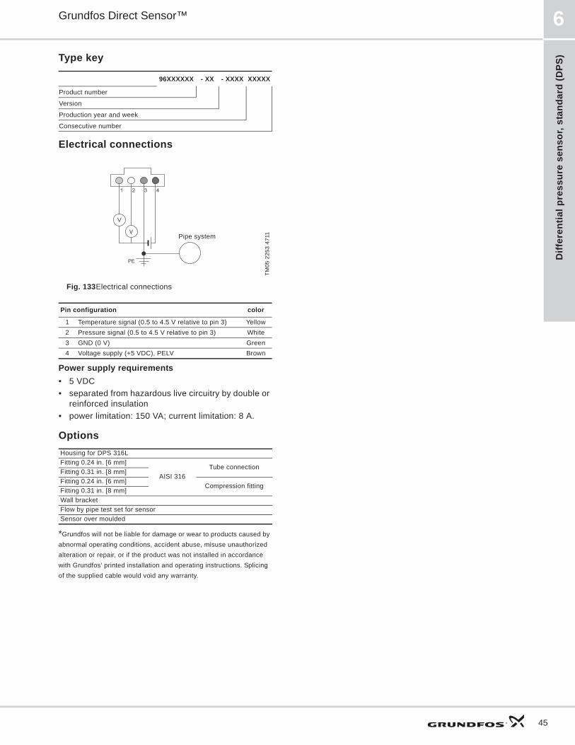
Diff
eren
tial p
ress
ure
sens
or, s
tand
ard
(DPS
)
Grundfos Direct Sensor™ 6
45
Type key
Electrical connections
Fig. 133Electrical connections
Power supply requirements• 5 VDC• separated from hazardous live circuitry by double or
reinforced insulation• power limitation: 150 VA; current limitation: 8 A.
Options
*Grundfos will not be liable for damage or wear to products caused by abnormal operating conditions, accident abuse, misuse unauthorized alteration or repair, or if the product was not installed in accordance with Grundfos' printed installation and operating instructions. Splicing of the supplied cable would void any warranty.
96XXXXXX - XX - XXXX XXXXX
Product number
Version
Production year and week
Consecutive number
TM05
225
3 47
11
Pin configuration color
1 Temperature signal (0.5 to 4.5 V relative to pin 3) Yellow2 Pressure signal (0.5 to 4.5 V relative to pin 3) White3 GND (0 V) Green4 Voltage supply (+5 VDC), PELV Brown
Housing for DPS 316LFitting 0.24 in. [6 mm]
AISI 316Tube connection
Fitting 0.31 in. [8 mm]Fitting 0.24 in. [6 mm]
Compression fittingFitting 0.31 in. [8 mm]Wall bracket Flow by pipe test set for sensorSensor over moulded
V
V
4321
PE
Pipe system

Differential pressure sensor, standard (D
PS)
Grundfos Direct Sensor™6
46
DPS 0-9 psi [0-0.6 bar]Differential pressure sensor, standard 0-9 psi series 100
Fig. 134DPS sensor
Dimension in. [mm]
Fig. 135 Dimensional sketches of sensing elementP1 is the high-pressure side
Fig. 136Isometric view of housing for DPS
Output signals
Fig. 137Differential pressure response
Fig. 138Temperature response
Specifications
TM04
445
7 13
09TM
04 4
456
1612
TM04
445
5 16
12TM
04 4
449
1612
TM04
445
8 16
12
0.79 in. [20 mm]
0.09
in. [
2.3
mm
]
0.08
in. [
2 m
m]
0.44 in. [11.2 mm]
0.50 in. [12.6 mm]
0.80
in. [
20.3
mm
]
1.89
in. [
47.9
mm
}
0.80
in. [
20.2
mm
]
0.44 in. [11.2 mm]
0.57 in. [14.6 mm]
R 0.05 in. [1.18 mm]
0.06 in. [1.5 mm]
1/8-27 NPT
1.57 in. [40 mm]
1/8-27 NPT
1.38 in. [35 mm]
1.30 in. [32.9 mm]
1.22
in. [
31 m
m]
1.30
in. [
33 m
m]
0.0
0.5
1.0
1.5
2.0
2.5
3.0
3.5
4.0
4.5
5.0
PressureMeasuring range (differential) 0 to 9 psi [0 to 0.6 bar]
Accuracy (± 1 ), 77 to 176 °F [25 to 80 °C] ± 2 % FS
Accuracy (± 1 ), 32 to 212 °F [0 to 100 °C] ± 3.0 % FS
Response time < 0.5 sSystem pressure deviation 0.09 psi/psi [6 mbar/bar]Resolution 0.02 psi [1.2 mbar]
Temperature Measuring range 32 to 212 °F [0 to 100 °C]Accuracy (± 1 ), 77 to 176 °F [25 to 80 °C] ± 1.8 °F [± 1 °C]
Accuracy (± 1 ), 32 to 212 °F [0 to 100 °C] ± 3.6 °F [± 2 °C]
Response time, sensing element to output change < 1.0 s
Resolution ± 0.36 °F [± 0.2 °C]
Media and EnvironmentMedia Liquids, air, and gasesMedia temperature (operation) 32 to 212 °F [0 to 100 °C]
Media temperature (peak) -13 to 248 °F [-25 to 120 °C], media must not freeze
Ambient air temp. (operation) -13 to 140 °F [-25 to 95 °C]Ambient air temp. (peak) -67 to 194 °F [-55 to 90 °C]Humidity (relative) 0 to 95 %, non-condensing
Application pressure P1
Max. 232 psi at 158 °F [Max. 16 bar at 70 °C] Max. 174 psi at 212 °F [Max. 12 bar at 100 °C]
Differential pressure P1 to P2 Max. |145| psi [Max. |10| bar]Burst pressure P1 Max. 435.1 psi [Max. 30 bar]Burst pressure P2 Max. 145 psi [Max. 10 bar]
Electrical data
Power supply 5 VDC (± 5 %). Grounding of the sensor supply is required.
Output signals RatiometricPressure signal 0.5 to 4.5 VTemperature signal 0.5 to 4.5 VPower consumption < 50 mWLoad impedance > 10 k
Sensor materialsSensing element Silicon-based MEMS sensorSealing Cap EPDM rubberHousing Composite (PPS)Wetted materials Corrosion-res coating, EPDM, PPS
Environmental standardsEnclosure class IP44Temperature cycling IEC 68-2-14Vibration (non-destructive) 20 to 2000 Hz, 10G, 4hElectromagnetic compatibility EN 61326-1
Dimensions
Sensing element 1.85 x 1.57 x 0.79 in. [47 X 40 X 20 mm]

Diff
eren
tial p
ress
ure
sens
or, s
tand
ard
(DPS
)
Grundfos Direct Sensor™ 6
47
DPS 0-14.5 psi [0-1.0 bar]Differential pressure sensor, standard 0-14.5 psi series 100
Fig. 139DPS sensor
Dimension in. [mm]
Fig. 140 Dimensional sketches of sensing elementP1 is the high-pressure side
Fig. 141Isometric view of housing for DPS
Output signals
Fig. 142Differential pressure response
Fig. 143Temperature response
Specifications
TM04
445
7 13
09TM
04 4
456
1612
TM04
445
5 16
12TM
04 4
450
1612
TM04
445
8 16
12
0.79 in. [20
0.09
in. [
2.3
0.08
in. [
2
0.44 in. [11.2
0.50 in. [12.6
0.80
in. [
20.3
1.89
in. [
47.9
0.80
in. [
20.2
0.44 in. [11.2
0.57 in. [14.6
R 0.05 in. [1.18
0.06 in. [1.5
1/8-27 NPT
1.57 in. [40 mm]
1/8-27 NPT
1.38 in. [35 mm]
1.30 in. [32.9 mm]
1.22
in. [
31 m
m]
1.30
in. [
33 m
m]
0.0
0.5
1.0
1.5
2.0
2.5
3.0
3.5
4.0
4.5
5.0
PressureMeasuring range (differential) 0 to 14.5 psi [0 to 1.0 bar]
Accuracy (±1 ), 77 to 176 °F [25 to 80 °C] ±2 % FS
Accuracy (±1 ), 32 to 212 °F [0 to 100 °C] ±3.0 % FS
Response time < 0.5 sSystem pressure deviation 0.09 psi/psi [6 mbar/bar]Resolution 0.02 psi [1.2 mbar]
Temperature Measuring range 32 to 212 °F [0 to 100 °C]Accuracy (±1 ), 77 to 176 °F [25 to 80 °C] ± 1.8 °F [± 1 °C]
Accuracy (±1 ), 32 to 212 °F [0 to 100 °C] ± 3.6 °F [± 2 °C]
Response time, sensing element to output change < 1.0 s
Resolution ± 0.36 °F [± 0.2 °C]
Media and EnvironmentMedia Liquids, air, and gasesMedia temperature (operation) 32 to 212 °F [0 to 100 °C]
Media temperature (peak) -13 to 248 °F [-25 to 120 °C], media must not freeze
Ambient air temp. (operation) -13 to 140 °F [-25 to 95 °C]Ambient air temp. (peak) -67 to 194 °F [-55 to 90 °C]Humidity (relative) 0 to 95 %, non-condensing
Application pressure P1
Max. 232 psi at 158 °F [Max. 16 bar at 70 °C]Max. 174 psi at 212 °F [Max. 12 bar at 100 °C]
Differential pressure P1 to P2 Max. |145| psi [Max. |10| bar]Burst pressure P1 Max. 435.1 psi [Max. 30 bar]Burst pressure P2 Max. 145 psi [Max. 10 bar]
Electrical dataPower supply 5 VDC (±5 %).Output signals RatiometricPressure signal 0.5 to 4.5 VTemperature signal 0.5 to 4.5 VPower consumption < 50 mWLoad impedance > 10 k
Sensor materialsSensing element Silicon-based MEMS sensorSealing Cap EPDM rubberHousing Composite (PPS)Wetted materials Corrosion-res. coating, EPDM, PPS
Environmental standardsEnclosure class IP44 (over moulded)Temperature cycling IEC 68-2-14Vibration (non-destructive) 20 to 2000 Hz, 10G, 4hElectromagnetic compatibility EN 61326-1
Dimensions
Sensing element 1.85 x 1.57 x 0.79 in. [47 X 40 X 20 mm]
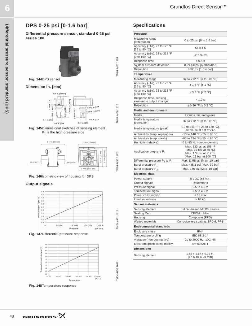
Differential pressure sensor, standard (D
PS)
Grundfos Direct Sensor™6
48
DPS 0-25 psi [0-1.6 bar]Differential pressure sensor, standard 0-25 psi series 100
Fig. 144DPS sensor
Dimension in. [mm]
Fig. 145Dimensional sketches of sensing elementP1 is the high-pressure side
Fig. 146Isometric view of housing for DPS
Output signals
Fig. 147Differential pressure response
Fig. 148Temperature response
Specifications
TM04
445
7 13
09TM
04 4
456
1612
TM04
445
5 16
12TM
04 4
451
1612
TM04
445
8 16
12
0.79 in. [20 mm]
0.09
in. [
2.3
0.08
in. [
2 m
m]
0.44 in. [11.2
0.50 in. [12.6
0.80
in. [
20.3
1.89
in. [
47.9
mm
}
0.80
in. [
20.2
0.44 in. [11.2
0.57 in. [14.6
R 0.05 in. [1.18
0.06 in. [1.5 mm]
1/8-27 NPT
1.57 in. [40 mm]
1/8-27 NPT
1.38 in. [35 mm]
1.30 in. [32.9 mm]
1.22
in. [
31 m
m]
1.30
in. [
33 m
m]
0.0
0.5
1.0
1.5
2.0
2.5
3.0
3.5
4.0
4.5
5.0
PressureMeasuring range (differential) 0 to 25 psi [0 to 1.6 bar]
Accuracy (±1 ), 77 to 176 °F [25 to 80 °C] ±2 % FS
Accuracy (±1 ), 32 to 212 °F [0 to 100 °C] ±2.5 % FS
Response time < 0.5 sSystem pressure deviation 0.09 psi/psi [6 mbar/bar]Resolution 0.02 psi [1.6 mbar]
Temperature Measuring range 32 to 212 °F [0 to 100 °C]Accuracy (±1 ), 77 to 176 °F [25 to 80 °C] ± 1.8 °F [± 1 °C]
Accuracy (±1 ), 32 to 212 °F [0 to 100 °C] ± 3.6 °F [± 2 °C]
Response time, sensing element to output change < 1.0 s
Resolution ± 0.36 °F [± 0.2 °C]
Media and environmentMedia Liquids, air, and gasesMedia temperature (operation) 32 to 212 °F [0 to 100 °C]
Media temperature (peak) -13 to 248 °F [-25 to 120 °C], media must not freeze
Ambient air temp. (operation) -13 to 140 °F [-25 to 95 °C]Ambient air temp. (peak) -67 to 194 °F [-55 to 90 °C]Humidity (relative) 0 to 95 %, non-condensing
Application pressure P1
Max. 232 psi at 158 °F [Max. 16 bar at 70 °C]Max. 174 psi at 212 °F [Max. 12 bar at 100 °C]
Differential pressure P1 to P2 Max. |145| psi [Max. 10 bar]Burst pressure P1 Max. 435.1 psi [Max. 30 bar]Burst pressure P2 Max. 145 psi [Max. 10 bar]
Electrical dataPower supply 5 VDC (±5 %). Output signals RatiometricPressure signal 0.5 to 4.5 VTemperature signal 0.5 to 4.5 VPower consumption < 50 mWLoad impedance > 10 k
Sensor materialsSensing element Silicon-based MEMS sensorSealing Cap EPDM rubberHousing Composite (PPS)Wetted materials Corrosion-res coating, EPDM, PPS
Environmental standardsEnclosure class IP44Temperature cycling IEC 68-2-14Vibration (non-destructive) 20 to 2000 Hz, 10G, 4hElectromagnetic compatibility EN 61326-1
Dimensions
Sensing element 1.85 x 1.57 x 0.79 in. [47 X 40 X 20 mm]
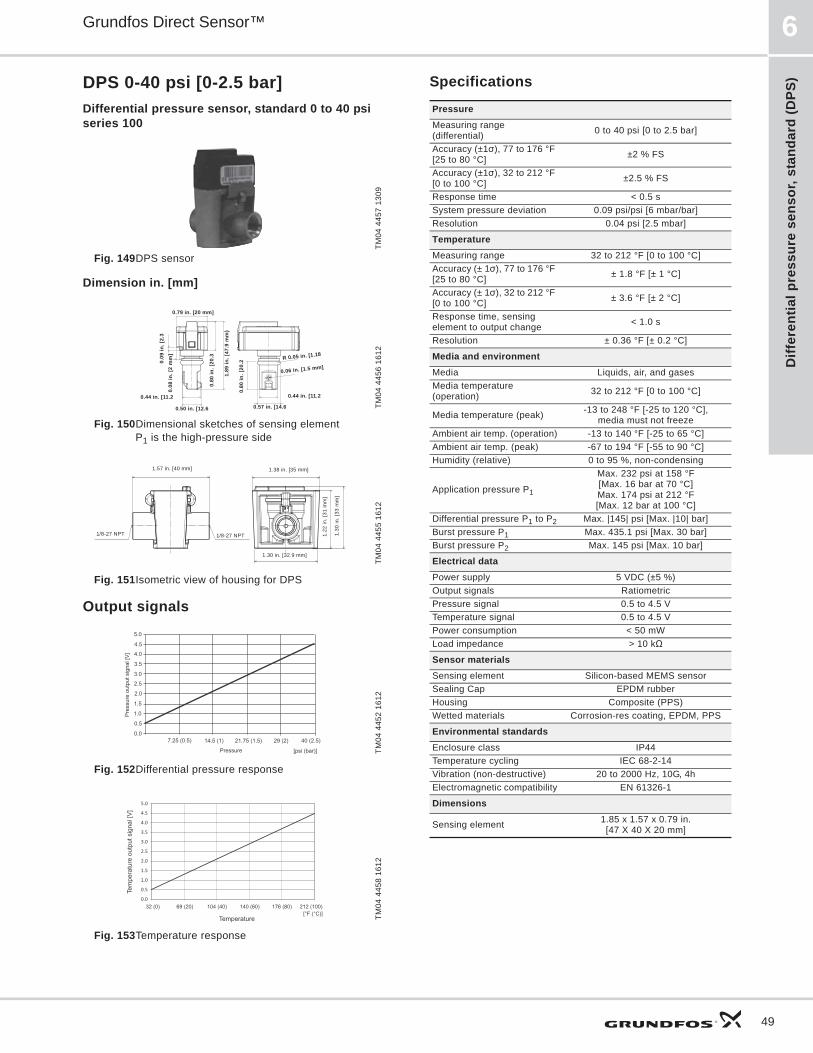
Diff
eren
tial p
ress
ure
sens
or, s
tand
ard
(DPS
)
Grundfos Direct Sensor™ 6
49
DPS 0-40 psi [0-2.5 bar]Differential pressure sensor, standard 0 to 40 psi series 100
Fig. 149DPS sensor
Dimension in. [mm]
Fig. 150Dimensional sketches of sensing elementP1 is the high-pressure side
Fig. 151Isometric view of housing for DPS
Output signals
Fig. 152Differential pressure response
Fig. 153Temperature response
Specifications
TM04
445
7 13
09TM
04 4
456
1612
TM04
445
5 16
12TM
04 4
452
1612
TM04
445
8 16
12
0.79 in. [20 mm]
0.09
in. [
2.3
0.08
in. [
2 m
m]
0.44 in. [11.2
0.50 in. [12.6
0.80
in. [
20.3
1.89
in. [
47.9
mm
}
0.80
in. [
20.2
0.44 in. [11.2
0.57 in. [14.6
R 0.05 in. [1.18
0.06 in. [1.5 mm]
1/8-27 NPT
1.57 in. [40 mm]
1/8-27 NPT
1.38 in. [35 mm]
1.30 in. [32.9 mm]
1.22
in. [
31 m
m]
1.30
in. [
33 m
m]
0.0
0.5
1.0
1.5
2.0
2.5
3.0
3.5
4.0
4.5
5.0
PressureMeasuring range (differential) 0 to 40 psi [0 to 2.5 bar]
Accuracy (±1 ), 77 to 176 °F [25 to 80 °C] ±2 % FS
Accuracy (±1 ), 32 to 212 °F [0 to 100 °C] ±2.5 % FS
Response time < 0.5 sSystem pressure deviation 0.09 psi/psi [6 mbar/bar]Resolution 0.04 psi [2.5 mbar]
Temperature Measuring range 32 to 212 °F [0 to 100 °C]Accuracy (± 1 ), 77 to 176 °F [25 to 80 °C] ± 1.8 °F [± 1 °C]
Accuracy (± 1 ), 32 to 212 °F [0 to 100 °C] ± 3.6 °F [± 2 °C]
Response time, sensing element to output change < 1.0 s
Resolution ± 0.36 °F [± 0.2 °C]
Media and environmentMedia Liquids, air, and gasesMedia temperature (operation) 32 to 212 °F [0 to 100 °C]
Media temperature (peak) -13 to 248 °F [-25 to 120 °C], media must not freeze
Ambient air temp. (operation) -13 to 140 °F [-25 to 65 °C]Ambient air temp. (peak) -67 to 194 °F [-55 to 90 °C]Humidity (relative) 0 to 95 %, non-condensing
Application pressure P1
Max. 232 psi at 158 °F[Max. 16 bar at 70 °C]Max. 174 psi at 212 °F [Max. 12 bar at 100 °C]
Differential pressure P1 to P2 Max. |145| psi [Max. |10| bar]Burst pressure P1 Max. 435.1 psi [Max. 30 bar]Burst pressure P2 Max. 145 psi [Max. 10 bar]
Electrical dataPower supply 5 VDC (±5 %)Output signals RatiometricPressure signal 0.5 to 4.5 VTemperature signal 0.5 to 4.5 VPower consumption < 50 mWLoad impedance > 10 k
Sensor materialsSensing element Silicon-based MEMS sensorSealing Cap EPDM rubberHousing Composite (PPS)Wetted materials Corrosion-res coating, EPDM, PPS
Environmental standardsEnclosure class IP44Temperature cycling IEC 68-2-14Vibration (non-destructive) 20 to 2000 Hz, 10G, 4hElectromagnetic compatibility EN 61326-1
Dimensions
Sensing element 1.85 x 1.57 x 0.79 in. [47 X 40 X 20 mm]

Differential pressure sensor, standard (D
PS)
Grundfos Direct Sensor™6
50
DPS 0-60 psi [0-4.0 bar]Differential pressure sensor, standard 0-60 psi series 100
Fig. 154DPS sensor
Dimension in. [mm]
Fig. 155Dimensional sketches of sensing elementP1 is the high-pressure side
Fig. 156 Isometric view of housing for DPS
Output signals
Fig. 157Differential pressure response
Fig. 158 Temperature response
Specifications
TM04
445
7 13
09TM
04 4
456
1612
TM04
445
5 16
12TM
04 4
453
1612
TM04
445
8 16
12
0.79 in. [20 mm]
0.09
in. [
2.3
0.08
in. [
2 m
m]
0.44 in. [11.2
0.50 in. [12.6
0.80
in. [
20.3
1.89
in. [
47.9
mm
}
0.80
in. [
20.2
0.44 in. [11.2
0.57 in. [14.6
R 0.05 in. [1.18
0.06 in. [1.5 mm]
1/8-27 NPT
1.57 in. [40 mm]
1/8-27 NPT
1.38 in. [35 mm]
1.30 in. [32.9 mm]
1.22
in. [
31 m
m]
1.30
in. [
33 m
m]
0.0
0.5
1.0
1.5
2.0
2.5
3.0
3.5
4.0
4.5
5.0
PressureMeasuring range (differential) 0 to 60 psi [0 to 4.0 bar]
Accuracy (±1 ), 77 to 176 °F [25 to 80 °C] ±2 % FS
Accuracy (±1 ), 32 to 212 °F [0 to 100 °C] ±2.5 % FS
Response time < 0.5 sSystem pressure deviation 0.09 psi/psi [6 mbar/bar]Resolution 0.06 psi [4 mbar]
Temperature Measuring range 32 to 212 °F [0 to 100 °C]Accuracy (±1 ), 77 to 176 °F [25 to 80 °C] ± 1.8 °F [± 1 °C]
Accuracy (±1 ), 32 to 212 °F [0 to 100 °C] ± 3.6 °F [± 2 °C]
Response time, sensing element to output change < 1.0 s
Resolution ± 0.36 °F [± 0.2 °C]
Media and environmentMedia Liquids, air, and gasesMedia temperature (operation) 32 to 212 °F [0 to 100 °C]
Media temperature (peak) -13 to 248 °F [-25 to 120 °C], media must not freeze
Ambient air temp. (operation) -13 to 140 °F [-25 to 95 °C]Ambient air temp. (peak) -67 to 194 °F [-55 to 90 °C]Humidity (relative) 0 to 95 %, non-condensing
Application pressure P1
Max. 232 psi at 158 °F[Max. 16 bar at 70 °C]Max. 174 psi at 212 °F [Max. 12 bar at 100 °C]
Differential pressure P1 to P2 Max. |145| psi [Max. |10| bar]Burst pressure P1 Max. 435.1 psi [Max. 30 bar]Burst pressure P2 Max. 145 psi [Max. 10 bar]
Electrical dataPower supply 5 VDC (±5 %)Output signals RatiometricPressure signal 0.5 to 4.5 VTemperature signal 0.5 to 4.5 VPower consumption < 50 mWLoad impedance > 10 k
Sensor materialsSensing element Silicon-based MEMS sensorSealing Cap EPDM rubberHousing Composite (PPS)Wetted materials Corrosion-res coating, EPDM, PPS
Environmental standardsEnclosure class IP44Temperature cycling IEC 68-2-14Vibration (non-destructive) 20 to 2000 Hz, 10G, 4hElectromagnetic compatibility EN 61326-1
Dimensions
Sensing element 1.85 x 1.57 x 0.79 in. [47 X 40 X 20 mm]

Diff
eren
tial p
ress
ure
sens
or, s
tand
ard
(DPS
)
Grundfos Direct Sensor™ 6
51
DPS 0-90 psi [0-6.0 bar]Differential pressure sensor, standard 0-90 psi series 100
Fig. 159DPS sensor
Dimension in. [mm]
Fig. 160Dimensional sketches of sensing elementP1 is the high-pressure side
Fig. 161Isometric view of housing for DPS
Output signals
Fig. 162Differential pressure response
Fig. 163Temperature response
Specifications
TM04
445
7 13
09TM
04 4
456
1612
TM04
445
5 13
09TM
04 5
111
1309
TM04
445
8 16
12
0.79 in. [20 mm]
0.09
in. [
2.3
0.08
in. [
2 m
m]
0.44 in. [11.2
0.50 in. [12.6
0.80
in. [
20.3
1.89
in. [
47.9
mm
}
0.80
in. [
20.2
0.44 in. [11.2
0.57 in. [14.6
R 0.05 in. [1.18
0.06 in. [1.5 mm]
1/8-27 NPT
1.57 in. [40 mm]
1/8-27 NPT
1.38 in. [35 mm]
1.30 in. [32.9 mm]
1.22
in. [
31 m
m]
1.30
in. [
33 m
m]
0.0
0.5
1.0
1.5
2.0
2.5
3.0
3.5
4.0
4.5
5.0
PressureMeasuring range (differential) 0 to 90 psi [0 to 6.0 bar]
Accuracy (±1 ), 77 to 176 °F [25 to 80 °C] ±2 % FS
Accuracy (±1 ), 32 to 212 °F [0 to 100 °C] ±2.5 % FS
Response time < 0.5 sSystem pressure deviation 0.09 psi/psi [6 mbar/bar]Resolution 0.09 psi [6 mbar]
Temperature Measuring range 32 to 212 °F [0 to 100 °C]Accuracy (±1 ), 77 to 176 °F [25 to 80 °C] ± 1.8 °F [± 1 °C]
Accuracy (±1 ), 32 to 212 °F [0 to 100 °C] ± 3.6 °F [± 2 °C]
Response time, sensing element to output change < 1.0 s
Resolution ± 0.36 °F [± 0.2 °C]
Media and environmentMedia Liquids, air, and gasesMedia temperature (opp) 32 to 212 °F [0 to 100 °C]
Media temperature (peak) -13 to 248 °F [-25 to 120 °C], media must not freeze
Ambient air temp. (opp.) -13 to 140 °F [-25 to 65 °C]Ambient air temp. (peak) -67 to 194 °F [-55 to 90 °C]Humidity (relative) 0 to 95 %, non-condensing
Application pressure P1
Max. 232 psi at 158 °F [Max. 16 bar at 70 °C]Max. 174 psi at 212 °F [Max. 12 bar at 100 °C]
Differential pressure P1 to P2 Max. |145| psi [Max. |10| bar]Burst pressure P1 Max. 435.1 psi [Max. 30 bar]Burst pressure P2 Max. 145 psi [Max. 10 bar]
Electrical dataPower supply (ground req) 5 VDC (±5 %) Output signals RatiometricPressure signal 0.5 to 4.5 VTemperature signal 0.5 to 4.5 VPower consumption < 50 mWLoad impedance > 10 k
Sensor materialsSensing element Silicon-based MEMS sensorSealing Cap EPDM rubberHousing Composite (PPS)Wetted materials Corrosion-res coating, EPDM, PPS
Environmental standardsEnclosure class IP44Temperature cycling IEC 68-2-14Vibration (non-destructive) 20 to 2000 Hz, 10G, 4hElectromagnetic compatibility EN 61326-1
Dimensions
Sensing element 1.85 x 1.57 x 0.79 in. [47 X 40 X 20 mm]

Product range-RPI Transm
itter
Grundfos Direct Sensor™7
52
7. Product range-RPI TransmitterScope of delivery:• RPI transmitter• M12- 16.4ft [5 meter] cable• Quick guide
Complete productPressure range
Thread Temperature measurement
O-ringProduct number
psi [bar] EPDM FKMRPI
0 to 9[0.6 bar] G1/2"
97748907977489489774892697748957
0 to 14.5[1.0 bar]
97748908977489499774892897748958
0 to 25[1.6 bar]
97748909977489509774892997748959
0 to 40[2.5 bar]
97748910977489519774893097748960
0 to 60[4.0 bar]
97748921977489529774894197748961
0 to 90[6.0 bar]
97748922977489539774894297748962
0 to 145[10.0 bar]
9774892397748944
97748963
0 to 232[16.0 bar]
97748924977489559774894597748964
0 to 360[25.0 bar]
97748925977489569774894697748955

Prod
uct r
ange
- R
PS s
enso
r
Grundfos Direct Sensor™ 8
53
8. Product range - RPS sensor• Scope of delivery• RPS sensor• Quick guide:
Complete productPressure range O-ring
Product numberpsi [bar] EPDM
RPS 0 to 9[0.6 bar]
96701190
0 to 14.5[1.0 bar]
96701202
0 to 25[1.6 bar]
96701203
0 to 40[2.5 bar]
96701204
0 to 60[4.0 bar]
96657081
0 to 90[6.0 bar]
96701205
0 to 145[10.0 bar]
96701206
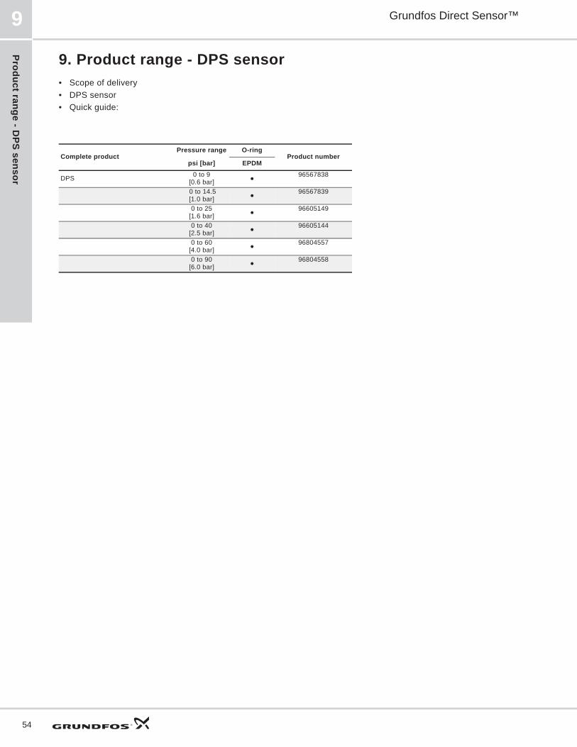
Product range - DPS sensor
Grundfos Direct Sensor™9
54
9. Product range - DPS sensor• Scope of delivery• DPS sensor• Quick guide:
Complete productPressure range O-ring
Product numberpsi [bar] EPDM
DPS 0 to 9[0.6 bar]
96567838
0 to 14.5[1.0 bar]
96567839
0 to 25[1.6 bar]
96605149
0 to 40[2.5 bar]
96605144
0 to 60[4.0 bar]
96804557
0 to 90[6.0 bar]
96804558

Prod
uct r
ange
- D
PI tr
ansm
itter
V.2
Grundfos Direct Sensor™ 10
55
10. Product range - DPI transmitter V.2Scope of delivery:• DPI V.2 transmitter• M12- 16.4ft [5 meter] cable• Capillary pipe• Quick guide
Complete productPressure range
Thread Temperature measurement
O-ringProduct number
[psi] EPDM FKMDPI
0 to 9 G1/2"
97747194977472159774720297747244
0 to 14.5
97747195977472169774720397747195
0 to 25
97747196977472189774720497747246
0 to 40
97747197977472199774720596841440
0 to 60
97747198977472209774720696841441
0 to 90
97747199977472419774720797747250
0 to 145
97747200977472429774720897747251
0 to 232
97747201977472439774720997747252
0 to 360
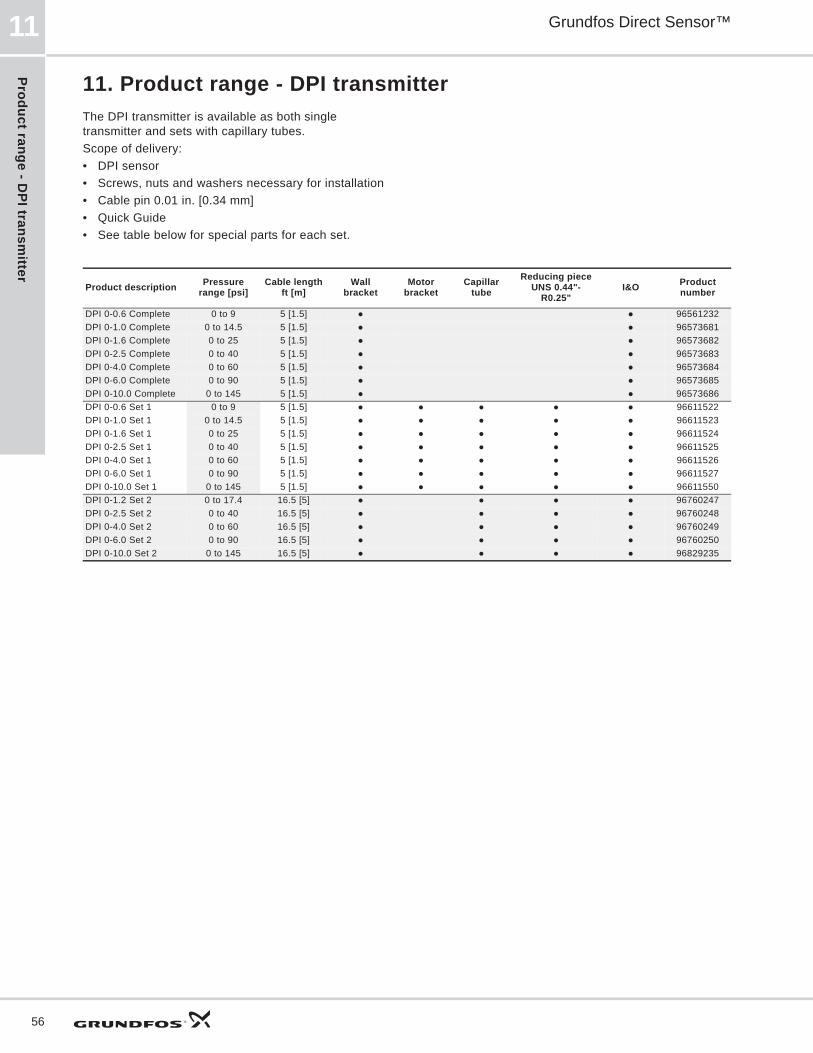
Product range - DPI transm
itter
Grundfos Direct Sensor™11
56
11. Product range - DPI transmitterThe DPI transmitter is available as both single transmitter and sets with capillary tubes.Scope of delivery:• DPI sensor • Screws, nuts and washers necessary for installation• Cable pin 0.01 in. [0.34 mm]• Quick Guide• See table below for special parts for each set.
Product description Pressure range [psi]
Cable lengthft [m]
Wallbracket
Motor bracket
Capillartube
Reducing pieceUNS 0.44"-
R0.25"I&O Product
number
DPI 0-0.6 Complete 0 to 9 5 [1.5] 96561232DPI 0-1.0 Complete 0 to 14.5 5 [1.5] 96573681DPI 0-1.6 Complete 0 to 25 5 [1.5] 96573682DPI 0-2.5 Complete 0 to 40 5 [1.5] 96573683DPI 0-4.0 Complete 0 to 60 5 [1.5] 96573684DPI 0-6.0 Complete 0 to 90 5 [1.5] 96573685DPI 0-10.0 Complete 0 to 145 5 [1.5] 96573686DPI 0-0.6 Set 1 0 to 9 5 [1.5] 96611522DPI 0-1.0 Set 1 0 to 14.5 5 [1.5] 96611523DPI 0-1.6 Set 1 0 to 25 5 [1.5] 96611524DPI 0-2.5 Set 1 0 to 40 5 [1.5] 96611525DPI 0-4.0 Set 1 0 to 60 5 [1.5] 96611526DPI 0-6.0 Set 1 0 to 90 5 [1.5] 96611527DPI 0-10.0 Set 1 0 to 145 5 [1.5] 96611550DPI 0-1.2 Set 2 0 to 17.4 16.5 [5] 96760247DPI 0-2.5 Set 2 0 to 40 16.5 [5] 96760248DPI 0-4.0 Set 2 0 to 60 16.5 [5] 96760249DPI 0-6.0 Set 2 0 to 90 16.5 [5] 96760250DPI 0-10.0 Set 2 0 to 145 16.5 [5] 96829235

Acc
esso
ries
Grundfos Direct Sensor™ 12
57
12. Accessories
Sensor interface, type SI 001 PSUSI 001 PSU from Grundfos Direct Sensors™ is an external power supply for the DPI and other transmitters with 24 VDC supply voltage.The power supply is to be used where the distance between the transmitter and the controller is longer than 100 ft [30 m].
Fig. 164Sensor interface, SI 001 PSU
Specification• Voltage range: 110-400 VAC• frequency range: 50-60 Hz• ambient temperature: -20 to +50 °C• enclosure class: IP54.
TM04
419
4 08
09
Part Product No.
Sensor interface, SI 001 PSU 96915820
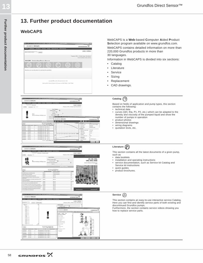
Further product documentation
Grundfos Direct Sensor™13
58
13. Further product documentation
WebCAPS
WebCAPS is a Web-based Computer Aided Product Selection program available on www.grundfos.com.WebCAPS contains detailed information on more than 220,000 Grundfos products in more than 30 languages.Information in WebCAPS is divided into six sections:• Catalog• Literature• Service• Sizing• Replacement• CAD drawings.
Catalog
Based on fields of application and pump types, this section contains the following:• technical data• curves (QH, Eta, P1, P2, etc.) which can be adapted to the
density and viscosity of the pumped liquid and show the number of pumps in operation
• product photos• dimensional drawings• wiring diagrams• quotation texts, etc.
Literature
This section contains all the latest documents of a given pump, such as• data booklets• installation and operating instructions• service documentation, such as Service kit Catalog and
Service kit instructions• quick guides• product brochures.
Service
This section contains an easy-to-use interactive service Catalog. Here you can find and identify service parts of both existing and discontinued Grundfos pumps.Furthermore, the section contains service videos showing you how to replace service parts.
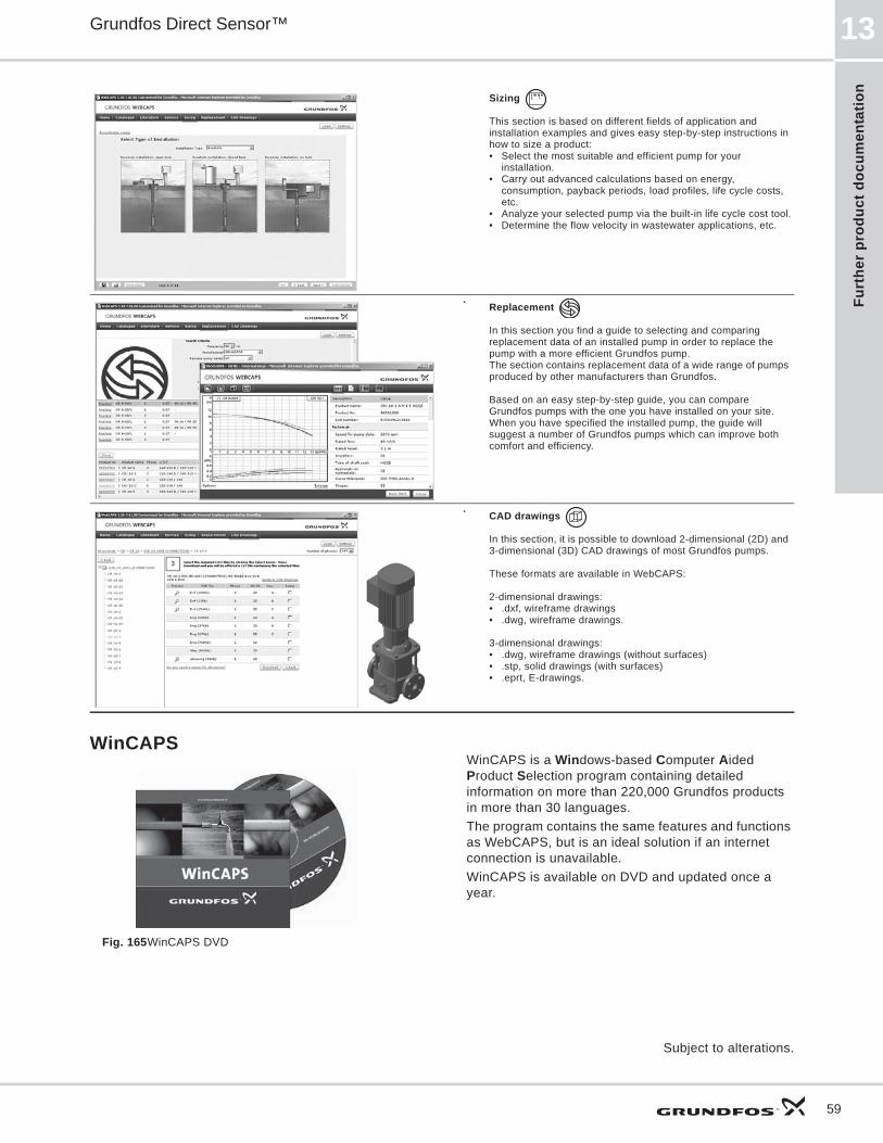
Furt
her
prod
uct d
ocum
enta
tion
Grundfos Direct Sensor™ 13
59
WinCAPS
Fig. 165WinCAPS DVD
WinCAPS is a Windows-based Computer Aided Product Selection program containing detailed information on more than 220,000 Grundfos products in more than 30 languages.The program contains the same features and functions as WebCAPS, but is an ideal solution if an internet connection is unavailable.WinCAPS is available on DVD and updated once a year.
Sizing
This section is based on different fields of application and installation examples and gives easy step-by-step instructions in how to size a product:• Select the most suitable and efficient pump for your
installation.• Carry out advanced calculations based on energy,
consumption, payback periods, load profiles, life cycle costs, etc.
• Analyze your selected pump via the built-in life cycle cost tool.• Determine the flow velocity in wastewater applications, etc.
Replacement
In this section you find a guide to selecting and comparing replacement data of an installed pump in order to replace the pump with a more efficient Grundfos pump. The section contains replacement data of a wide range of pumps produced by other manufacturers than Grundfos.
Based on an easy step-by-step guide, you can compare Grundfos pumps with the one you have installed on your site. When you have specified the installed pump, the guide will suggest a number of Grundfos pumps which can improve both comfort and efficiency.
CAD drawings
In this section, it is possible to download 2-dimensional (2D) and 3-dimensional (3D) CAD drawings of most Grundfos pumps.
These formats are available in WebCAPS:
2-dimensional drawings:• .dxf, wireframe drawings• .dwg, wireframe drawings.
3-dimensional drawings:• .dwg, wireframe drawings (without surfaces)• .stp, solid drawings (with surfaces)• .eprt, E-drawings.
0 1
Subject to alterations.

GRUNDFOS Pumps Corporation 17100 West 118th TerraceOlathe, Kansas 66061Phone: +1-913-227-3400 Telefax: +1-913-227-3500
GRUNDFOS Canada Inc. 2941 Brighton Road Oakville, Ontario L6H 6C9 CanadaPhone: +1-905 829 9533 Telefax: +1-905 829 9512
Bombas GRUNDFOS de Mexico S.A. de C.V. Boulevard TLC No. 15Parque Industrial Stiva AeropuertoApodaca, N.L. Mexico 66600Phone: +52-81-8144 4000 Telefax: +52-81-8144 4010
The name Grundfos, the Grundfos logo, and the payoff Be–Think–Innovate are registrated trademarks owned by Grundfos Management A/S or Grundfos A/S, Denmark. All rights reserved worldwide.
Being responsible is our foundationThinking ahead makes it possible
Innovation is the essence
L-DS-PG-002 0812
ECM: -


