® Job Name: Job Number: Model Numbers: Page SPECIFICATION SUBMITTAL 369368 Rev. B 1 06.02.11 Control Interfaces GRX-IO GRX-IO Control Interface Description • Integrates a GRAFIK Eye® lighting control system with equipment that has a contact-closure I/O, including: – Motion and occupant sensors. – Timeclocks and push buttons. – Motorized projection screens, skylights, window shades, and movable walls. – AV equipment. – Security systems. • May be programmed to control any combination of one to eight GRAFIK Eye® 3000 or 4000 Series control units. Inputs/Outputs • Provides five inputs and five outputs. • Provides both normally open (NO) and normally closed (NC) contacts. • Using the inputs, contact closures in other equipment can operate control units to: – Select scenes. – Adjust scenes to reflect status of movable walls. – Turn lights on or off based on room occupancy. • Using the outputs, scene changes in control units can: – Trigger outputs to control other equipment. – Provide status feedback to other equipment.
Transcript
®
Job Name:
Job Number:
Model Numbers:
PageSPECIFICATION SUBMITTAL
369368 Rev. B 1 06.02.11
Control InterfacesGRX-IO
GRX-IO Control Interface
Description
•IntegratesaGRAFIKEye®lightingcontrolsystemwith equipment that has a contact-closure I/O, including:
– Motion and occupant sensors. – Timeclocks and push buttons. –Motorizedprojectionscreens,skylights,window
shades, and movable walls. – AV equipment. –Securitysystems.•Maybeprogrammedtocontrolanycombinationof onetoeightGRAFIKEye® 3000 or 4000 Series control units.
Five Status LEDs light when associated output is active(on).
System Communications and Capacity
IEC PELV/NEC® Class 2 wiring connects GRX-IO Interface to control units and other components. Countstowardsystemmaximumof16wallstations/controlinterfaces(3poweredfromoneGRAFIKEye®controlunitwithoutexternal12 V powersupply;GRX-IOcountsastwodevicestowardthemaximumofthreeconnectedtooneGRAFIKEye®3000controlunit).
contact closure, solid state, open collector, or active-low(NPN)/activehigh(PNP)output.
- Open collector NPN or active-low on-state voltage must be less than 2 V and sink 3.0 mA.
- Open collector PNP or active-high on-state voltage must be greater than 12 V and source 3.0 mA.
Five Output Terminals
•Providemaintainedormomentary(1-second)outputs.
•TheGRX-IOisnotratedtocontrolunclamped,inductive loads. Inductive loads include, but are notlimitedto,relays,solenoids,andmotors.Tocontrolthesetypesofequipment,aflybackdiodemustbeused(DCvoltagesonly).Seediagrambelow.
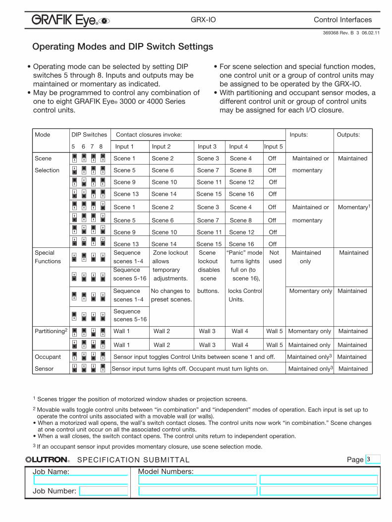
Scene Scene 1 Scene 2 Scene 3 Scene 4 Off Maintained or Maintained
Selection Scene5Scene6Scene7Scene8Offmomentary
Scene 9 Scene 10 Scene 11 Scene 12 Off
Scene13Scene14Scene15Scene16Off
Scene1Scene2Scene3Scene4OffMaintainedorMomentary1
Scene5Scene6Scene7Scene8Offmomentary
Scene 9 Scene 10 Scene 11 Scene 12 Off
Scene13Scene14Scene15Scene16Off Special Sequence Zone lockout Scene “Panic” mode Not Maintained MaintainedFunctionsscenes1-4allowslockoutturnslightsused only Sequencetemporarydisablesfullon(to scenes5-16adjustments.scenescene16),
Sequence No changes to buttons. locks Control MomentaryonlyMaintained scenes 1-4 preset scenes. Units.
•Withpartitioningandoccupantsensormodes,adifferent control unit or group of control units maybeassignedforeachI/Oclosure.
1 Scenes trigger the position of motorized window shades or projection screens.
2 Movable walls toggle control units between “in combination” and “independent” modes of operation. Each input is set up to operatethecontrolunitsassociatedwithamovablewall(orwalls).
• When a motorized wall opens, the wall’s switch contact closes. The control units now work “in combination.” Scene changes at one control unit occur on all the associated control units.
1. Mount the control interface directly on a wall, as shown in the Mounting Diagram, using screws (not included). When mounting, provide sufficient space for connecting cables.
The unit can also be placed in the LUT-19AV-1U AV rack using the screws provided with the unit. The LUT-19AV-1U will hold up to four units.
If conduit is desired for wiring, the LUT-5x10-ENC can be used to mount one unit.
2. Strip 4 in (10 mm) of insulation from wires. Each data link terminal will accept up to two 18 AWG (1.0 mm2) wires.
3. Connect wiring as shown in the Wiring Diagram (next page). LED 1 lights continuously (Power) and LED 7 blinks rapidly (Data Link RX) when the IEC PELV/NEC® Class 2 Data Link is installed correctly.
LUT-19AV-1U
Wire Strip Length
4 in (10 mm)
5.26
4.263.75
2.50
1.06
Control Interface
Wall
Mounting Diagram
LUT-5x10-ENC
0.25 (6.4)
0.34 (8.6) dia.
0.18 (4.6) dia.
0.18 (4.6) dia.
#6 or #8 (M3 or M4) screw recommended (not included)
Mounting Hole DetailDimensions: in (mm)
®
Job Name:
Job Number:
Model Numbers:
PageSPECIFICATION SUBMITTAL
369368Rev.B506.02.11
Control InterfacesGRX-IO
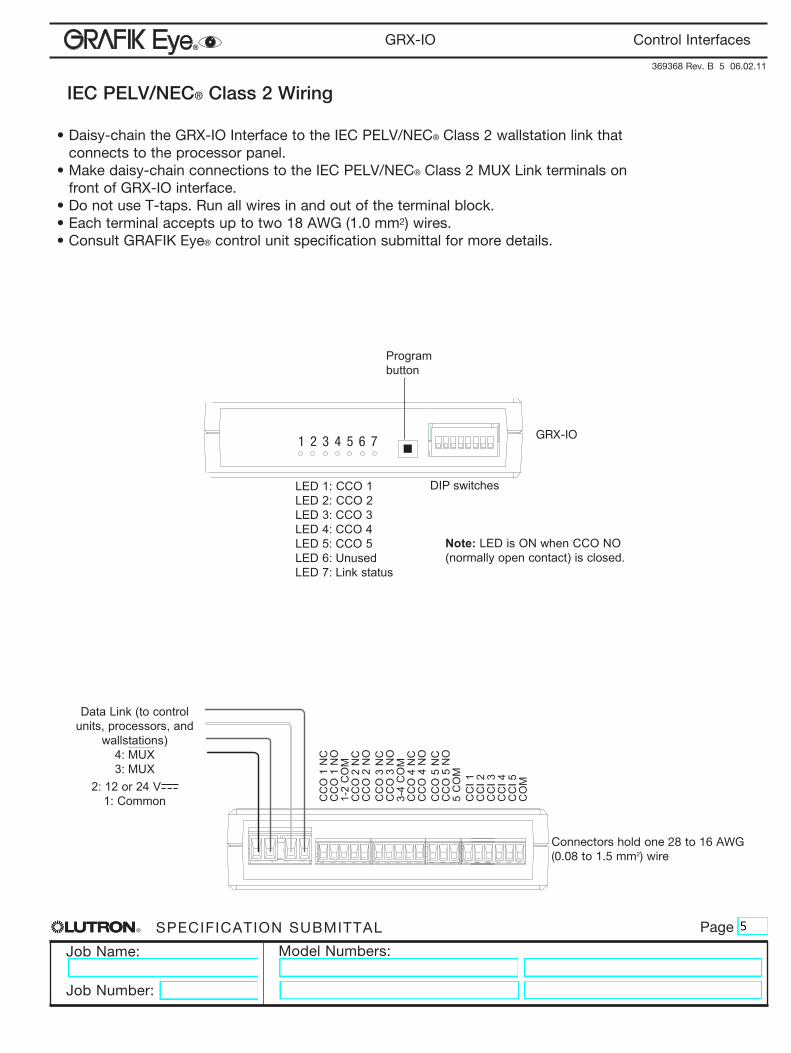
•Daisy-chaintheGRX-IOInterfacetotheIECPELV/NEC® Class 2 wallstation link that connects to the processor panel.
•Makedaisy-chainconnectionstotheIECPELV/NEC® Class 2 MUX Link terminals on front of GRX-IO interface.
•DonotuseT-taps.Runallwiresinandoutoftheterminalblock.•Eachterminalacceptsuptotwo18AWG(1.0mm2)wires.•ConsultGRAFIKEye® control unit specification submittal for more details.
Note: LED is ON when CCO NO (normally open contact) is closed.
4 3 2 1
Connectors hold one 28 to 16 AWG (0.08to1.5mm2)wire
Data Link (to control units, processors, and
wallstations) 4: MUX3: MUX
2: 12 or 24 V1: Common C
CO
1 N
CC
CO
1 N
O1-
2 C
OM
CC
O 2
NC
CC
O 2
NO
CC
O 3
NC
CC
O 3
NO
3-4
CO
MC
CO
4 N
CC
CO
4 N
OC
CO
5 N
CC
CO
5 N
O5
CO
MC
CI 1
CC
I 2C
CI 3
CC
I 4C
CI 5
CO
M
®
Job Name:
Job Number:
Model Numbers:
PageSPECIFICATION SUBMITTAL
369368 Rev. B 6 06.02.11
Control InterfacesGRX-IO
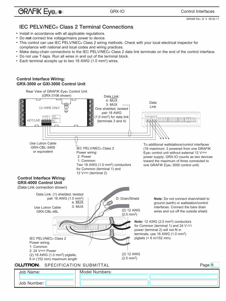
IEC PELV/NEC® Class 2 Terminal Connections• Install in accordance with all applicable regulations.•Do not connect line voltage/mains power to device.• This control can use IEC PELV/NEC® Class 2 wiring methods. Check with your local electrical inspector for
compliance with national and local codes and wiring practices.• Makedaisy-chainconnectionstotheIEC PELV/NEC® Class 2 data link terminals on the end of the control interface. • DonotuseT-taps.Runallwiresinandoutoftheterminalblock.• Eachterminalacceptsuptotwo18AWG(1.0mm2) wires.
HOT/LIVE
CU WIRE ONLY
CLASS 21 2 3 4
USAClass 2IECPELV
To additional wallstations/control interfaces (16maximum;3poweredfromoneGRAFIKEye® control unit without external 12 V powersupply;GRX-IOcountsastwodevicestoward the maximum of three connected to oneGRAFIKEye®3000controlunit)
Control Interface Wiring: GRX-3000 or GXI-3000 Control Unit
RearViewofGRAFIKEye® Control Unit (GRX-3106shown)
Use Lutron Cable GRX-CBL-346S
or equivalent
Data Link
Data Link:4: MUX3: MUX
One shielded, twisted pair18AWG
(1.0mm2) for data link (terminals 3 and 4)
IEC PELV/NEC® Class 2 Power wiring: 2: Power 1: CommonTwo18AWG(1.0mm2) conductors for Common (terminal 1) and 12 V (terminal 2)
IEC PELVNEC® Class 2 Power wiring:1: Common2: 24 V Power(2)18AWG(1.0mm2) pigtails, 6 in (152 mm) maximum length
D:Drain/Shield
(2)12AWG(2.5 mm2)
(2)12AWG(2.5 mm2)
Data Link: (1) shielded, twisted pair18AWG(1.0mm2)
4: MUX3: MUX
Control Interface Wiring: GRX-4000 Control Unit (Data Link connection shown)
Note: 12AWG(2.5mm2) conductors for Common (terminal 1) and 24 V power (terminal 2) will not fit in terminals;use18AWG(1.0mm2) pigtails (< 6 in/152 mm).
Note: Do not connect drain/shield to ground (earth) or wallstation/control interfaces. Connect the bare drain wires and cut off the outside shield.