Exploration & Production This document is the property of Total. It must not be stored, reproduced or disclosed to others without written authorisation from the Company. GENERAL SPECIFICATION ENVIRONMENT GS EP ENV 421 Landfill design and operation for E&P sites 03 01/2011 Complete review and update 02 10/2005 Addition of EP root to document identification 01 10/2003 Change of Group name and logo 00 04/2001 Old TotalFina SP ENV 430 (10/99) Rev. Date Notes Owner: EP/HSE Managing entity: EP/HSE
Transcript
Exploration & Production
This document is the property of Total. It must not be stored, reproduced or disclosed to others without written authorisation from the Company.
GENERAL SPECIFICATION
ENVIRONMENT
GS EP ENV 421
Landfill design and operation for E&P sites
03 01/2011 Complete review and update
02 10/2005 Addition of EP root to document identification
01 10/2003 Change of Group name and logo
00 04/2001 Old TotalFina SP ENV 430 (10/99)
Rev. Date Notes
Owner: EP/HSE Managing entity: EP/HSE
Exploration & Production
General Specification Date : 01/2011
GS EP ENV 421 Rev : 03
This document is the property of Total. It must not be stored, reproduced or disclosed to others without written authorisation from the Company.
8.3 Monitoring procedures in the operational phases ............................................................ 20
8.4 Closure and aftercare procedures ................................................................................... 22
Exploration & Production
General Specification Date : 01/2011
GS EP ENV 421 Rev : 03
This document is the property of Total. It must not be stored, reproduced or disclosed to others without written authorisation from the Company.
Page 3/27
Appendix 1 Examples of regulations .................................................................................... 23
Appendix 2 Quality control .................................................................................................... 26
Exploration & Production
General Specification Date : 01/2011
GS EP ENV 421 Rev : 03
This document is the property of Total. It must not be stored, reproduced or disclosed to others without written authorisation from the Company.
Page 4/27
1. Scope
1.1 Purpose The purpose of this General Specification is to define the general requirements for the design, construction and operation of landfills necessary to manage waste generated on E&P sites.
1.2 Applicability This General Specification applies to all affiliates and projects managed by the E&P branch, where a landfill is deemed necessary to manage waste generated during facilities construction or on operational exploration and production sites.
It shall be used for landfills built for Company use, whoever the landfill operator may be: Company or Contractor.
For landfills built to manage waste from other generators outside Company, some requirements may be considered not relevant. All required deviations from the present specification shall be managed under a derogation process.
The provisions included herein shall be applied in the absence of more stringent local regulations or standards.
2. Reference documents The reference documents listed below form an integral part of this General Specification. Unless otherwise stipulated, the applicable version of these documents, including relevant appendices and supplements, is the latest revision published at the EFFECTIVE DATE of the CONTRACT.
Standards
Reference Title
ISO 5667-1 Water quality - Sampling - Part 1: Guidance on the design of sampling programmes and sampling techniques
EN 13257/A1 Geotextile and geotextile-related products - Characteristics required for use in solid waste disposals
EN 13967/A1 Flexible sheets for waterproofing - Plastic and rubber damp proof sheets including plastic and rubber basement tanking sheet - Definitions and characteristics
EN 13984/A1 Flexible sheets for waterproofing - Plastic and rubber vapour control layers - Definitions and characteristics
Exploration & Production
General Specification Date : 01/2011
GS EP ENV 421 Rev : 03
This document is the property of Total. It must not be stored, reproduced or disclosed to others without written authorisation from the Company.
Page 5/27
Professional Documents
Reference Title
Report No. 413 Guidelines for waste management with special focus on areas with limited infrastructure, OGP, Rev 1.1, September 2008 (updated March 2009)
Regulations
Reference Title
Directive 1999/31/EC Of the Council of 26 April 1999 on the landfill of waste
Directive 2008/98/EC Of the European Parliament and of the Council of 19 November 2008 on waste and repealing certain Directives
40 CFR, Part 273 Code of Federal Regulations-Title 1: Protection of the Environment, Standards for universal waste management
Codes
Reference Title
Not applicable
Other documents
Reference Title
Not applicable
Total General Specifications
Reference Title
GS EP ENV 001 Environmental requirements for projects design and E&P activities
GS EP ENV 111 Baseline study environmental status of an onshore site
GS EP ENV 120 Environmental impact assessment for E&P activities
3. Terms and definitions Waste, hazardous waste, non-hazardous waste, inert waste: refer to GS EP ENV 001.
Biodegradable waste means waste capable of undergoing anaerobic or aerobic decomposition.
Exploration & Production
General Specification Date : 01/2011
GS EP ENV 421 Rev : 03
This document is the property of Total. It must not be stored, reproduced or disclosed to others without written authorisation from the Company.
Page 6/27
Landfill means a waste disposal site for the deposition of waste onto or into land, including internal waste disposal sites (i.e. landfills where a waste producer is carrying out its own waste disposal at the site of production). Facilities excluded are those where waste is temporarily stored in order to permit its preparation for later transport to other recovery, treatment or disposal facilities elsewhere, and temporary (i.e. less than one year) waste deposition prior to recovery, treatment or disposal.
Landfills are usually classified in one of three categories depending on the type of waste accepted: hazardous waste, non-hazardous waste, and inert waste (Directive 1999/31/EC).
Treatment means the physical, chemical or biological processes, including sorting, that change the characteristics of the waste in order to reduce toxicity or volume, to facilitate its handling or enhance recovery.
Leachate means any liquid percolating through the deposited waste and emitted from or contained within a landfill.
Landfill gas (or biogas) means gas generated by the anaerobic decomposition of organic waste; it is a mixture of methane and carbon dioxide, plus trace gas constituents.
Liner, geomembrane, or geosynthetics are generic term for all synthetic membranes used in geotechnical engineering.
Mineral barrier is the bottom portion of a landfill, composed of a low hydraulic conductivity clay layer that confines the waste and prevents leachate escape.
Composite barrier is the addition of a mineral barrier and a liner.
Drainage layer means a high hydraulic conductivity portion of a landfill base (or final cover) that promotes the movement of liquids, usually away from the impermeable layer.
Groundwater monitoring well means a small groundwater piezometer used to measure the water level and quality of the water bearing horizon. They are usually not more than 50 m deep.
Hydraulic conductivity is a coefficient of proportionality describing the rate at which water can move through a permeable medium. The density and kinematic viscosity of the water must be considered in determining hydraulic conductivity.
4. General principles As per GS EP ENV 001, waste generated during Company’s works and operations, shall be clearly identified, classified (at least as hazardous and non-hazardous) and quantified to allow their adequate collection, segregation, temporary storage, treatment and disposal.
A list of typical E&P waste with associated classification is provided in GS EP ENV 001.
Treatment and disposal options shall be selected in accordance with local regulations, taking into account the 5 R principles” waste management hierarchy “, i.e.: Reduce, Recover, Reuse, Recycle, Residue disposal.
When landfilling has been identified as some waste preferred disposal option, the site selection, facility design and operating conditions shall be defined in accordance with the present specification. Report No.413 should also be taken as reference.
Company may decide to subcontract landfill operation as well as engineering and construction. Company remains responsible for its waste, from generation to final disposal, even if it uses the services of a Contractor.
Exploration & Production
General Specification Date : 01/2011
GS EP ENV 421 Rev : 03
This document is the property of Total. It must not be stored, reproduced or disclosed to others without written authorisation from the Company.
Page 7/27
During the early stage of the landfill construction project, Company shall ensure that Environmental baseline study (EBS) and Environmental impacts Assessment (EIA) are carried out (GS EP ENV 111 and GS EP ENV 120).
Company shall ensure that landfill is adapted to the nature and quantities of waste, and to the environmental context, and that the proposal for the landfill construction contains at least the following requirements:
• A description of the types and total quantity of waste to be deposited
• The proposed capacity of the disposal site
• A description of the site, including its hydrological and geological characteristics
• The proposed methods for pollution prevention and abatement
• The proposed operation, monitoring and control plan
• The proposed plan for closure and aftercare procedures.
Company shall also ensure that all the regulatory permits required for the landfill construction and operation are granted.
5. Types of wastes concerned
5.1 Wastes categories The landfill may accept both hazardous and non-hazardous waste.
Should both hazardous and non-hazardous waste need to be disposed of at the same location, the landfill shall contain separated cells, one or more for each waste category.
Except otherwise stated by Company, inert wastes are normally excluded, their disposal being considered on a case by case basis, and under less stringent conditions than for hazardous and non-hazardous wastes.
5.2 Restrictions to waste disposal The following wastes are not allowed to be disposed of into the landfill:
• Liquid waste
• Wastes which, in the conditions of landfill, are explosive, corrosive, oxidizing, highly flammable or flammable
• Medical wastes which are infectious
• Radioactive wastes, except NORMS which may be accepted under specific conditions which shall be strictly defined and approved through a derogation process
• Any other type of waste which does not fulfill the acceptance criteria which shall be agreed with Company
• Hazardous wastes such as pasty and oily material shall not be disposed of into the landfill, unless they have received a preliminary treatment to enhance their cohesion, for example by stabilization with lime (CaO) and/or cement, at ratio depending on oil content. Acceptance criteria should include parameters such as dryness and hazardous components content in leachate.
Exploration & Production
General Specification Date : 01/2011
GS EP ENV 421 Rev : 03
This document is the property of Total. It must not be stored, reproduced or disclosed to others without written authorisation from the Company.
Page 8/27
6. Landfill design
6.1 Site location Landfills can be natural, topographic depressions and/or man-made excavations formed of earthen material. A key consideration for a landfill site is the guaranty to provide long-term containment. (Report No. 413).
The location of a landfill shall take into consideration requirements relating to:
• Distances from the site boundary to residential, recreation areas and waterways, water bodies and other agricultural or urban sites, ensuring a minimum separation of 0.5 km from residential areas
• The existence of a superficial aquifer, coastal water or protected areas
• The geological and hydrogeological conditions in the area
• The risk of flooding, and site instability
• The protection of the natural or cultural patrimony in the area.
The landfill can be authorized only if the characteristics of the site with respect to the above mentioned requirements, or the corrective measures to be taken, indicate that the environmental risk associated to the landfill is acceptable.
The landfill shall be located so that wind borne matter (dust, paper, etc.) from the site is not dispersed onto public roads and the surrounding land.
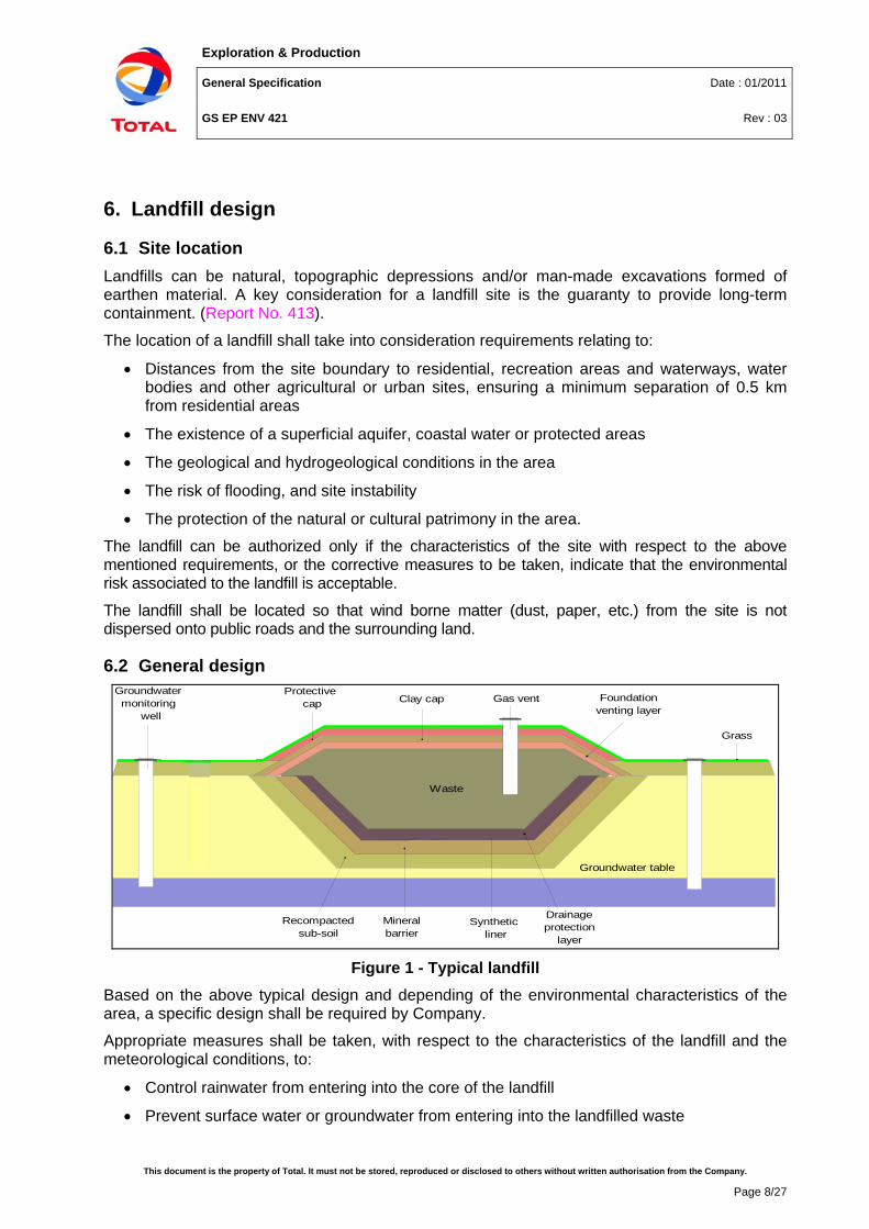
6.2 General design
Groundwater table
Waste
Groundwatermonitoring
wellGas monitoring
probe
Gas vent
Grass
Clay capProtective
cap Foundationventing layer
Drainageprotection
layer
Synthetic liner
Recompactedsub-soil
Mineralbarrier
Figure 1 - Typical landfill
Based on the above typical design and depending of the environmental characteristics of the area, a specific design shall be required by Company.
Appropriate measures shall be taken, with respect to the characteristics of the landfill and the meteorological conditions, to:
• Control rainwater from entering into the core of the landfill
• Prevent surface water or groundwater from entering into the landfilled waste
Exploration & Production
General Specification Date : 01/2011
GS EP ENV 421 Rev : 03
This document is the property of Total. It must not be stored, reproduced or disclosed to others without written authorisation from the Company.
Page 9/27
• Collect contaminated water and leachate. If an assessment based on consideration of the location of the landfill and the waste to be accepted shows that the landfill poses no potential risk to the environment, Company may decide that this provision does not apply
• Treat contaminated water and leachate collected from the landfill
• Collect and dispose biogas when necessary.
In the case of a superficial aquifer, the landfill shall not be positioned below the water table. The structure shall be raised to avoid any contact between the water table and the bottom of the mineral barrier.
The final cover shall be the same regardless of climate or site sensitivity.
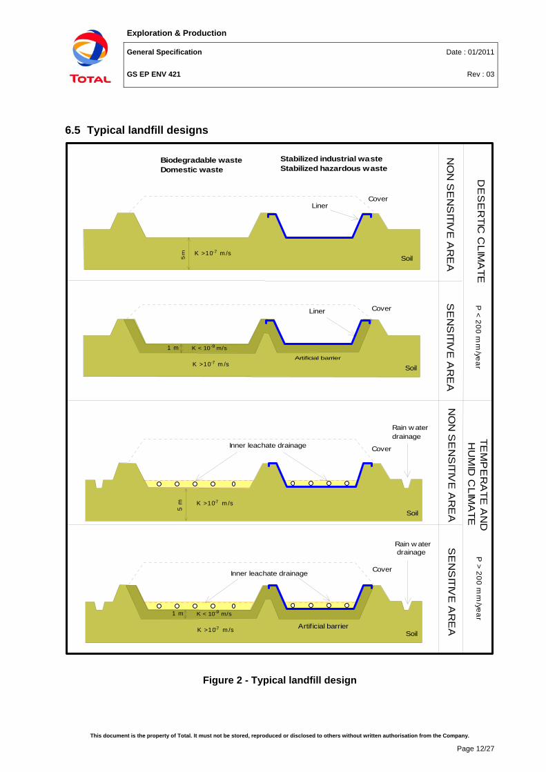
6.3 Design options Design criteria are based on two main parameters: site sensitivity and rainfall intensity. Depending on these criteria, four different designs have been developed. Site sensitivity is determined by the criteria given in the table below, but may also be defined on a case by case basis by Company.
Table 1 - Site sensitivity criteria 1 Non-sensitive
areas Hydraulic conductivity less than 10-7 m/s
Poor ecosystem
Unconfined aquifer not close to the surface (depth > 3 m)
No groundwater use by local population
No population near the site area
2 Sensitive areas Hydraulic conductivity greater than 10-7 m/s, layer thickness greater than 5 m
Rich and fragile ecosystem
Aquaculture or agriculture close to the selected site
Unconfined aquifer near the surface (depth < 3 m)
Groundwater used by local population
Socio-economy turned to agriculture, aquaculture or fishing
I Arid Climate Rain water precipitation less than 200 mm/year
II Temperate and humid climate
Rain water precipitation greater than 200 mm/year
The following tables summarize the minimum technical requirements for each criterion. The four general designs are illustrated by diagrams given in section 6.5. The detailed technical requirements are developed in the next section.
Exploration & Production
General Specification Date : 01/2011
GS EP ENV 421 Rev : 03
This document is the property of Total. It must not be stored, reproduced or disclosed to others without written authorisation from the Company.
Page 10/27
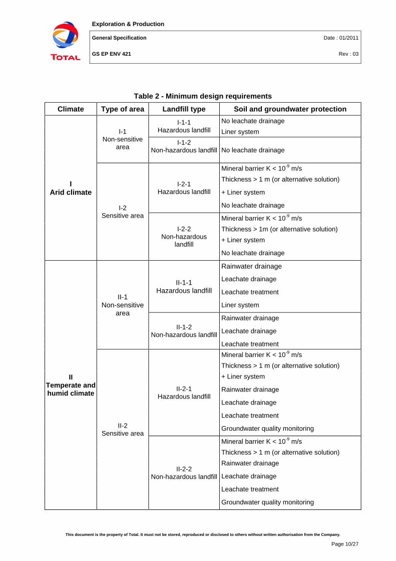
Table 2 - Minimum design requirements
Climate Type of area Landfill type Soil and groundwater protection
I Arid climate
I-1 Non-sensitive
area
I-1-1 Hazardous landfill
No leachate drainage Liner system
I-1-2 Non-hazardous landfill No leachate drainage
I-2 Sensitive area
I-2-1 Hazardous landfill
Mineral barrier K < 10-9 m/s Thickness > 1 m (or alternative solution)
+ Liner system
No leachate drainage
I-2-2 Non-hazardous
landfill
Mineral barrier K < 10-9 m/s Thickness > 1m (or alternative solution) + Liner system
No leachate drainage
II Temperate and humid climate
II-1 Non-sensitive
area
II-1-1 Hazardous landfill
Rainwater drainage
Leachate drainage
Leachate treatment
Liner system
II-1-2 Non-hazardous landfill
Rainwater drainage
Leachate drainage
Leachate treatment
II-2 Sensitive area
II-2-1 Hazardous landfill
Mineral barrier K < 10-9 m/s Thickness > 1 m (or alternative solution) + Liner system
Rainwater drainage
Leachate drainage
Leachate treatment
Groundwater quality monitoring
II-2-2 Non-hazardous landfill
Mineral barrier K < 10-9 m/s Thickness > 1 m (or alternative solution) Rainwater drainage
Leachate drainage
Leachate treatment
Groundwater quality monitoring
Exploration & Production
General Specification Date : 01/2011
GS EP ENV 421 Rev : 03
This document is the property of Total. It must not be stored, reproduced or disclosed to others without written authorisation from the Company.
Page 11/27
6.4 Landfill sizing Waste height shall be defined so as not to attain the stability limit of the embankment and not to alter the drainage system efficiency.
The landfill shall be subdivided into several cells to facilitate waste and leachate management.
Design assumptions for domestic and industrial waste production can be obtained from available data on other Company sites.
Exploration & Production
General Specification Date : 01/2011
GS EP ENV 421 Rev : 03
This document is the property of Total. It must not be stored, reproduced or disclosed to others without written authorisation from the Company.
This document is the property of Total. It must not be stored, reproduced or disclosed to others without written authorisation from the Company.
Page 13/27
7. Landfill construction
7.1 Site preparation – Stability The emplacement of waste on the site shall take place in such a way as to ensure the stability of the waste mass and associated structures, particularly with respect to the prevention of slope failure.
Where an artificial barrier is created it must be ascertained that, given the form of the landfill, the geological substratum is sufficiently stable to prevent settlement that may cause damage to the barrier.
7.2 Protection of soil and groundwater The landfill must be located and designed so as to meet the necessary conditions for preventing pollution of the soil, groundwater or surface water and ensuring efficient collection of leachate.
Protection of soil, groundwater and surface water is to be achieved by the combination of a geological barrier and, optionally, a bottom liner during the operational phase and by the combination of a geological barrier and a top liner during the post closure phase.
Construction Quality Control requirements are detailed in Appendix 2.
7.2.1 Mineral barriers The geological barrier is determined by geological and hydrogeological conditions below and in the vicinity of a landfill site providing sufficient attenuation capacity to prevent a potential risk to soil and groundwater.
The landfill base and sides shall consist of a mineral layer which satisfies hydraulic conductivity (K) and thickness requirements with a combined effect in terms of protection of soil, groundwater and surface water at least equivalent to the one resulting from the following requirements:
• Non sensitive site: K < 1.0 x 10⁻⁷ m/s thickness > 5 m
• Sensitive site: K < 1.0 x 10⁻⁹ m/s thickness > 1 m
Where the geological barrier does not naturally meet the above conditions it should be completed artificially and reinforced by other means providing equivalent protection. An artificially established geological barrier should be no less than 1 meter thick.
The requirements and characteristics of the mineral sealing layer in order of importance are:
• Low hydraulic conductivity at the field scale
• Long-term chemical compatibility with the substances to be contained
• High sorption capacity and low diffusion coefficient.
Indicative hydraulic conductivity are given here below for different rock types (Brassington R, Field Hydrogeology, Geological Society of London Handbook Series, Open University Press, 1988) :
• Coarse sand: K = 20 to 100 m/d (2.10-4 to 10-3 m/s)
• Fine sand: K = 1 to 5 m/d (10-5 to 5.10-5 m/s)
Exploration & Production
General Specification Date : 01/2011
GS EP ENV 421 Rev : 03
This document is the property of Total. It must not be stored, reproduced or disclosed to others without written authorisation from the Company.
Page 14/27
• Clay: K = 10-8 to 10-2 m/d (10-13 to 10-7 m/s)
• Gravel: K = 100 to 1000 m/d (10-3 to 10-1 m/s).
7.2.2 Liner system In addition to the geological barrier described above, liner and leachate collection systems must be added for hazardous landfills.
The geomembrane or alternative device shall be impermeable, chemically and mechanically compatible with the stored wastes.
Welded High Density Polyethylene (HDPE ≥ 1.5mm) is currently the most commonly used geomembrane for landfill bottom liner systems, due to its strength and chemical resistance to leachate constituents.
Geotextiles and geomembranes should be selected in accordance with European standards (EN 13257/A1 for geotextiles, EN 13967/A1 and EN 13984/A1 for geomembranes) or equivalent.
Liner placement shall limit as much as possible tensile and compressive stresses, in particular after waste placement. On-site control of geosynthetic placement shall focus on the following key points:
• Proper on-site storage
• Placement procedure
• After placement control (inspection, possible repairs)
• Placement of the upper layer.
7.3 Leachate collection
7.3.1 Drainage layer A drainage layer approximately 0.3 to 0.5 m thick shall cover the entire base of the landfill and shall be composed of clean gravels with a diameter of about 50 mm (40-60).
When geomembranes are used in the lining system, a protective bedding layer, usually consisting of a geotextile, should be placed between the drainage layer and the liner, to minimize the risk of puncturing the later.
Geocomposites should also be used, particularly on steep slopes, where granular material would not be stable.
The recommended hydraulic conductivity of granular drainage layers ranges from 10-4 to 10-3 m/s, due to clogging and maintenance considerations.
It is recommended to use a geotextile layer with a high percentage of openings to cover the drainage layer in order to avoid penetration of the finer portion of the overlying waste. A secondary 16 to 32 mm diameter gravel layer can be provided as an alternative component of the leachate collection system in the case of geotextile clogging.
The geotextile filter should be discontinuous allowing local direct hydraulic connection between the upper and lower drainage layers. In the case of clogging of both geotextile and upper parts of the drainage layer, the increase of seepage velocity due to the reduced available area for
Exploration & Production
General Specification Date : 01/2011
GS EP ENV 421 Rev : 03
This document is the property of Total. It must not be stored, reproduced or disclosed to others without written authorisation from the Company.
Page 15/27
seepage can avoid or delay complete clogging of the drainage system. Geotextile filters wrapped around pipe networks must be avoided.
Geotextile filter
WASTE
Geotextile for protection and
separation 50 mm Gravels
Leachate collecting pipe Geomembrane
16-32 mm Gravels
Openings in
Geotextile filte
r
CLAY LINER
Figure 3 - Drainage layer and collection pipes
7.3.2 Collection pipes The collection pipes shall be surrounded by gravel to protect the pipe from clogging; a filter layer shall be provided above the drainage layer to minimize clogging of the drainage layer and to protect it from damage by sharp objects and from equipment loads.
A leachate collection sump must be provided, where leachate is collected and stored temporarily.
Pipe diameters are typically 10 to 20 cm and base slopes should be a minimum 2 to 3%.
High Density Polyethylene (HDPE) pipe is currently the most commonly used pipe. The pipes should have a maximum possible percentage of open area and maximum opening dimensions, considering the required structural resistance of the pipes and the grain size distribution of the surrounding drainage material.
7.4 Rainwater drainage Leachate and rainwater management are among the main problems in landfill operation.
Leachate production shall be reduced as much as possible to avoid costly treatments. Three key factors reduce the quantity of rainwater coming in contact with leachates:
• External runoff drainage to avoid any flow entering the landfill area
• Drainage of the entire landfill area surface, except for the cell in operation
• Collection and separate treatment of waste leachates.
7.4.1 Rainfall runoff drainage Landfill design for humid climates shall ensure rainwater drainage by means of peripheral ditches to intercept and collect any runoff coming from surrounding land.
This drainage system should be designed to collect at least the ten year maximum rainfall.
7.4.2 Clean water separate network A liner, stabilized with sand bags, shall cover the entire surface of the landfill. A section of this liner should be rolled back for each waste input phase (see section 8). This requirement is
Exploration & Production
General Specification Date : 01/2011
GS EP ENV 421 Rev : 03
This document is the property of Total. It must not be stored, reproduced or disclosed to others without written authorisation from the Company.
Page 16/27
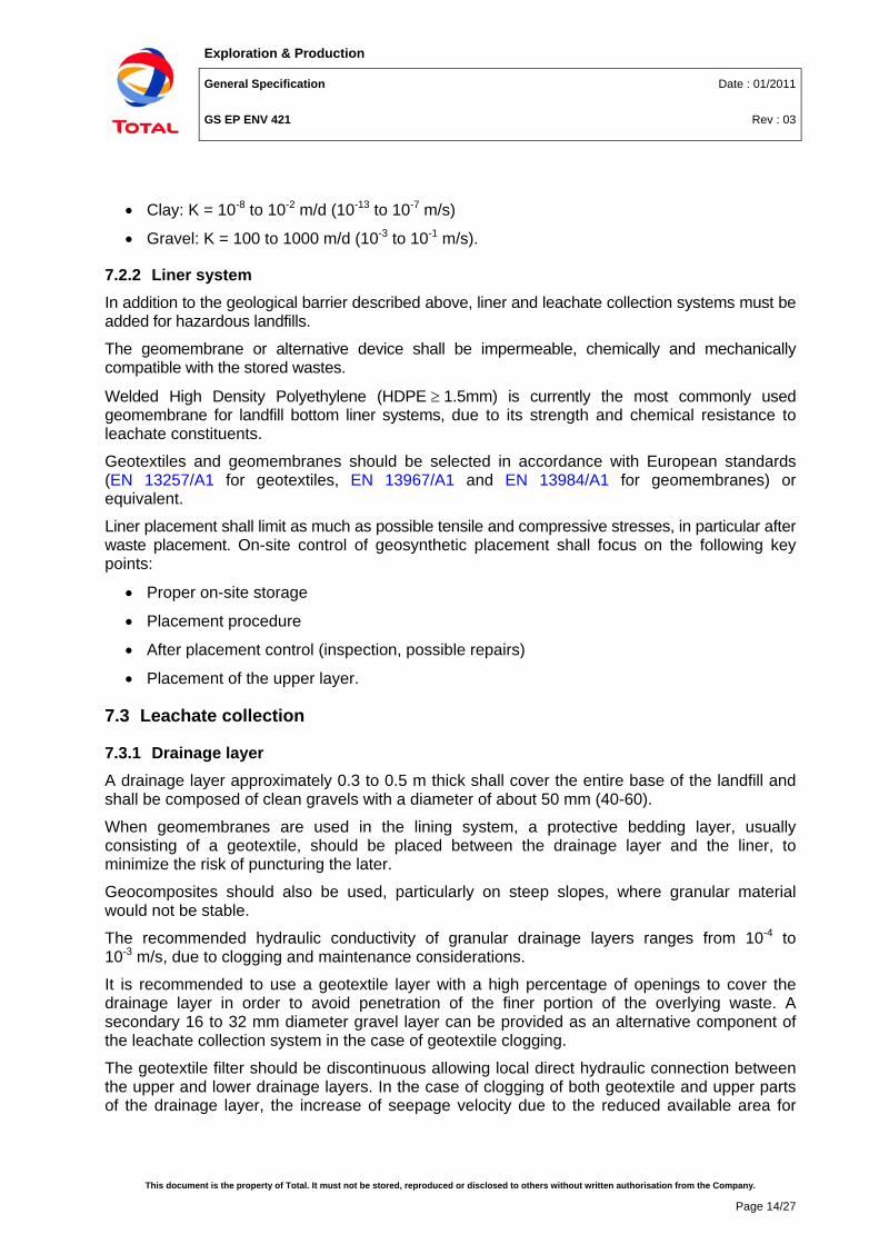
fundamental to reduce leachate production. This geomembrane shall be at least a sown Low Density PolyEthylene (LDPE) composition.
A separate drainage system (by gravity if possible) should remove rainwater from the landfill (see figure 4).
The non-operating cells can then be drained with a separate network independent from the operating cell leachate network.
CIRCULAR ROAD
OPERATING CELL
NON OPERATING CELL
CLEAN WATER DRAINAGE
LEACHATE DRAINAGE
TOP LINER
WASTECOVER
Clean waterdrainage
Figure 4 - Separate water and leachate networks for operating and non-operating cells
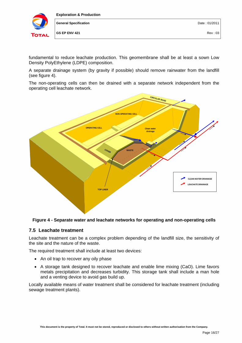
7.5 Leachate treatment Leachate treatment can be a complex problem depending of the landfill size, the sensitivity of the site and the nature of the waste.
The required treatment shall include at least two devices:
• An oil trap to recover any oily phase
• A storage tank designed to recover leachate and enable lime mixing (CaO). Lime favors metals precipitation and decreases turbidity. This storage tank shall include a man hole and a venting device to avoid gas build up.
Locally available means of water treatment shall be considered for leachate treatment (including sewage treatment plants).
Exploration & Production
General Specification Date : 01/2011
GS EP ENV 421 Rev : 03
This document is the property of Total. It must not be stored, reproduced or disclosed to others without written authorisation from the Company.
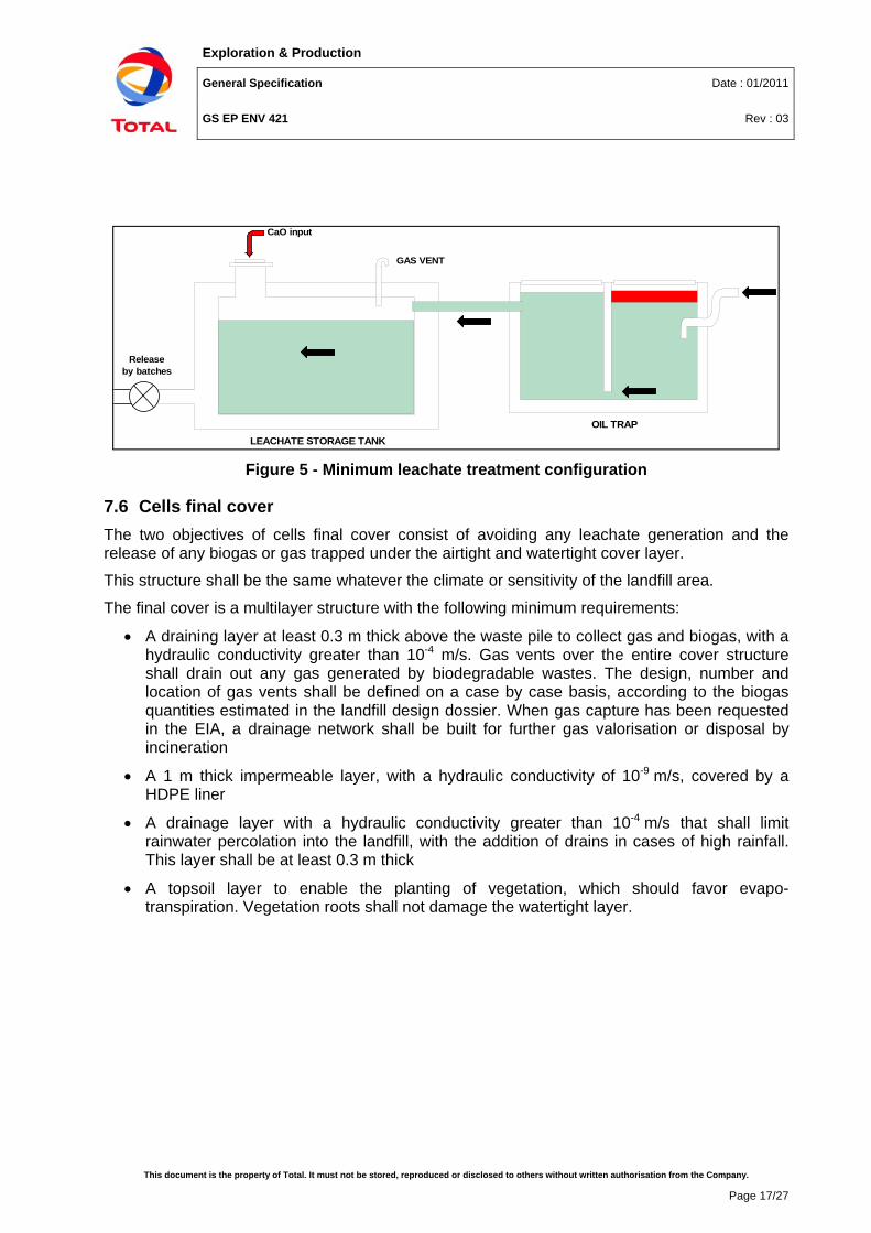
7.6 Cells final cover The two objectives of cells final cover consist of avoiding any leachate generation and the release of any biogas or gas trapped under the airtight and watertight cover layer.
This structure shall be the same whatever the climate or sensitivity of the landfill area.
The final cover is a multilayer structure with the following minimum requirements:
• A draining layer at least 0.3 m thick above the waste pile to collect gas and biogas, with a hydraulic conductivity greater than 10-4 m/s. Gas vents over the entire cover structure shall drain out any gas generated by biodegradable wastes. The design, number and location of gas vents shall be defined on a case by case basis, according to the biogas quantities estimated in the landfill design dossier. When gas capture has been requested in the EIA, a drainage network shall be built for further gas valorisation or disposal by incineration
• A 1 m thick impermeable layer, with a hydraulic conductivity of 10-9 m/s, covered by a HDPE liner
• A drainage layer with a hydraulic conductivity greater than 10-4 m/s that shall limit rainwater percolation into the landfill, with the addition of drains in cases of high rainfall. This layer shall be at least 0.3 m thick
• A topsoil layer to enable the planting of vegetation, which should favor evapo-transpiration. Vegetation roots shall not damage the watertight layer.
GAS VENT
LEACHATE STORAGE TANKOIL TRAP
CaO input
Release by batches
Exploration & Production
General Specification Date : 01/2011
GS EP ENV 421 Rev : 03
This document is the property of Total. It must not be stored, reproduced or disclosed to others without written authorisation from the Company.
Page 18/27
Gas vent
Top layer
Activated carbon
Composite layer :geomembrane mineral barrier
Waste
Vent layer
Drain layer
K < 10-9 m/s
K > 10-4 m/s
K > 10-4 m/s > 0.3 m
> 1 m
> 0.3 m
HDPE > 1.5 mm
Figure 6 - Multilayer cover structure
7.7 Groundwater monitoring wells For sensitive sites in temperate and humid climates, at least three piezometers are required to monitor quality of groundwater likely to be affected:
• Two of these piezometers shall be located down hydraulic gradient from the landfill
• The other(s) shall be located up hydraulic gradient from the landfill.
7.8 Fencing The landfill shall be surrounded by fencing sufficient to prevent free access to the site. The gates shall be locked outside of operating hours.
The system of control and access to each facility shall contain a series of measures to detect and discourage illegal dumping at the facility.
8. Landfill management and operation
8.1 Landfill management The landfill operator shall ensure the following requirements are complied with:
• Acceptance criteria agreed with Company shall be clearly made available to all waste generation sites
• Access to the landfill site shall be strictly reserved to authorized staff in charge of waste management
• Traffic organization and input scheduling shall be planned
• Waste transport, handling, and storage working procedures at the landfill site shall be defined after a risk analysis in industrial hygiene. Personnel shall be informed about waste hazards and shall wear adapted PPE
Exploration & Production
General Specification Date : 01/2011
GS EP ENV 421 Rev : 03
This document is the property of Total. It must not be stored, reproduced or disclosed to others without written authorisation from the Company.
Page 19/27
• A notice board shall display a storage map for each type of waste and shall specify the disposal modes, risks and security requirements.
• Measures shall be taken to minimize nuisances and risks arising from the landfill due to:
- Emissions of odors and dust
- Noise and traffic
- Formation of aerosols
- Fires.
8.2 Landfill operational procedures
8.2.1 Preliminaries requirements Prior to accepting the waste at the landfill site, the landfill operator shall ensure the following requirements are met:
• Visual inspection of wastes at the entrance and at the point of deposit and, as appropriate, verification of conformity with acceptance criteria
• Waste weighing (using weighing scale or bridge), unless weighing is performed at the generation site as agreed by Company
• Written acknowledgment of receipt of each delivery of waste accepted on the site (filling and signature of the Waste Tracking Form which accompanies all waste transfer from the generation site to the disposal site, to be returned to the waste generator as agreed with Company)
• Maintaining a register of the quantities and characteristics of the waste deposited, indicating origin, date of delivery, identity of the producer, and, in the case of hazardous wastes, the precise location on the site. This information shall be made available to Company when requested.
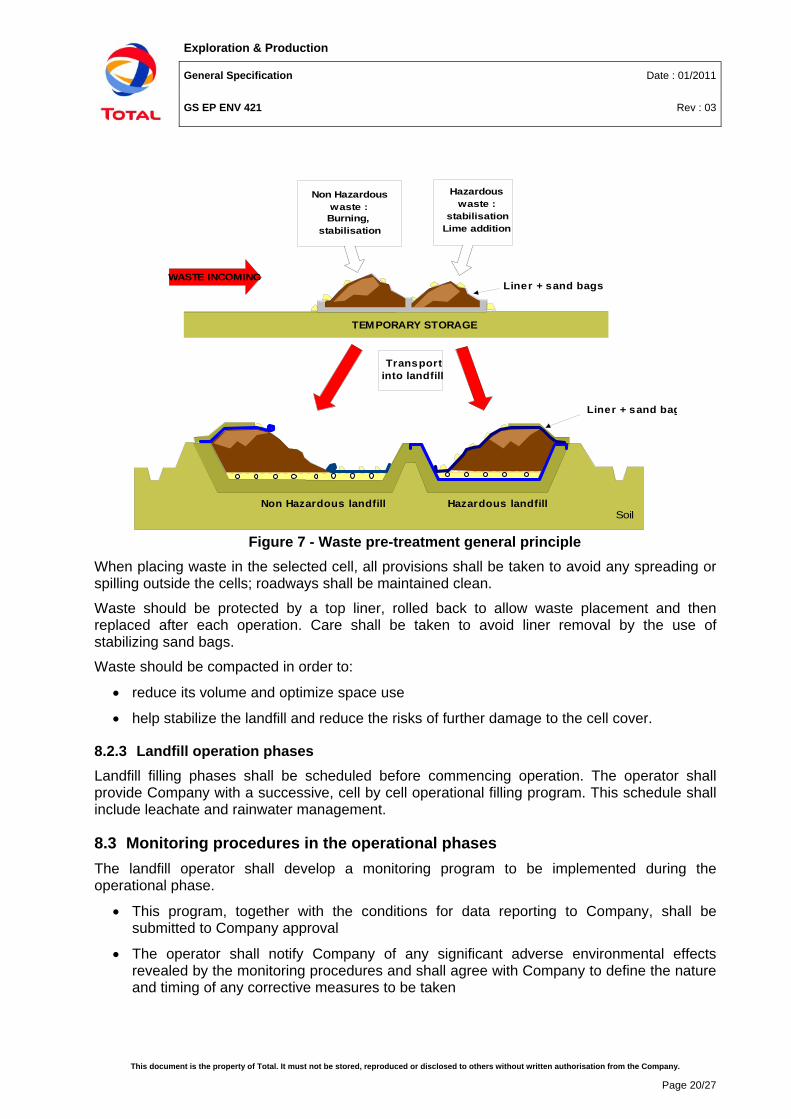
8.2.2 Waste preliminary treatment and disposal procedure Temporary storage should be avoided, especially for hazardous wastes. Hazardous waste shall not be temporarily stored directly on the ground.
After the acceptance procedure, wastes may need preliminary treatment at the landfill site, before being placed in the selected cell.
Pre-treatment operations such as oily waste stabilisation or non hazardous waste burning (see next paragraph), shall be realised on a specific concrete area, designed to avoid any spread outside the concrete slab.
In case landfilling has been selected as their preferred option instead of disposal at a properly designed incinerator, organic biodegradable burnable non-hazardous wastes should preferably be burnt at the landfill site, provided it’s compliant with local regulations, instead of being placed directly into the landfill.
Ashes should be covered as soon as possible by sand or soil to avoid any wind dispersion of matter or dust. Burnt residues shall be conveyed into the landfill.
Exploration & Production
General Specification Date : 01/2011
GS EP ENV 421 Rev : 03
This document is the property of Total. It must not be stored, reproduced or disclosed to others without written authorisation from the Company.
Page 20/27
SoilHazardous landfillNon Hazardous landfill
TEMPORARY STORAGE
Non Hazardous waste :
Burning, stabilisation
WASTE INCOMING
Hazardous waste :
stabilisationLime addition
Transport into landfill
Liner + sand bags
Liner + sand bag
Figure 7 - Waste pre-treatment general principle
When placing waste in the selected cell, all provisions shall be taken to avoid any spreading or spilling outside the cells; roadways shall be maintained clean.
Waste should be protected by a top liner, rolled back to allow waste placement and then replaced after each operation. Care shall be taken to avoid liner removal by the use of stabilizing sand bags.
Waste should be compacted in order to:
• reduce its volume and optimize space use
• help stabilize the landfill and reduce the risks of further damage to the cell cover.
8.2.3 Landfill operation phases Landfill filling phases shall be scheduled before commencing operation. The operator shall provide Company with a successive, cell by cell operational filling program. This schedule shall include leachate and rainwater management.
8.3 Monitoring procedures in the operational phases The landfill operator shall develop a monitoring program to be implemented during the operational phase.
• This program, together with the conditions for data reporting to Company, shall be submitted to Company approval
• The operator shall notify Company of any significant adverse environmental effects revealed by the monitoring procedures and shall agree with Company to define the nature and timing of any corrective measures to be taken
Exploration & Production
General Specification Date : 01/2011
GS EP ENV 421 Rev : 03
This document is the property of Total. It must not be stored, reproduced or disclosed to others without written authorisation from the Company.
Page 21/27
• The analyses, as well as the quality control of the analytical operations, for the monitoring procedures shall be carried out by competent laboratories
• Where leachate collection is performed and groundwater is present (temperate or humid climate and sensitive area), the minimum procedure for the monitoring to be carried out in order to verify water quality shall meet the requirements specified below.
8.3.1 Leachate and surface water quality monitoring Samples of leachate and surface water, if present, must be collected at representative points.
Sampling and measuring of leachate volume and composition must be performed separately at each point at which leachate is discharged from the site (ISO 5667-1).
Monitoring of surface water, if present, shall be carried out at not less than two points, one upstream from the landfill and one downstream.
The frequency of sampling and analysis is given here after.
For leachate and water, samples, representative of the average composition, shall be taken for monitoring:
• Leachate volume: Monthly
• Leachate composition: Quarterly
• Volume and composition of surface water: Quarterly.
If data evolution indicates that longer sampling intervals are equally effective, periodicity may be adapted accordingly. For leachates, conductivity shall be measured at least once a year.
On the basis of the characteristics of the landfill site, Company may determine that these measurements are not required.
Recommended analytical parameters include pH, TOC, heavy metals, TPH, COD, BOD.
8.3.2 Groundwater quality monitoring Sampling shall be carried out in at least three locations prior to the commencement of filling operations in order to establish reference values for future sampling.
The parameters to be analysed in the samples taken shall be derived from the expected composition of the leachate and the groundwater quality in the area. In selecting the parameters for analysis consideration should be given to groundwater mobility. Parameters should include indicators in order to ensure an early recognition of any change in water quality. Recommended parameters include pH, TOC, heavy metals, TPH, COD, BOD.
• Groundwater level: Six-monthly
• Groundwater composition: Six-monthly.
If groundwater level fluctuates or groundwater mobility is high, the frequency shall be increased.
8.3.3 Gas monitoring When gas capture has been considered necessary, a biogas monitoring program shall be defined and implemented (quarterly analyze of methane, carbon dioxide and oxygen content as a minimum).
Exploration & Production
General Specification Date : 01/2011
GS EP ENV 421 Rev : 03
This document is the property of Total. It must not be stored, reproduced or disclosed to others without written authorisation from the Company.
Page 22/27
8.4 Closure and aftercare procedures Closure, decommissioning and site restitution conditions, and aftercare procedures shall be considered as early as the pre-project phase, and shall be addressed in the landfill EIA.
Partial closure (one cell or more) may be considered under conditions agreed with Company.
At the end of the activities, the landfill closure and site restitution shall be treated as a standalone project: this project shall include conditions for aboveground facilities removal, reference and impact studies necessary to define the restoration measures, final status studies and aftercare/surveillance programs as necessary.
The closure conditions shall be agreed with Company and subject to Company formal approval, depending on the context (landfill ownership and operatorship).
Exploration & Production
General Specification Date : 01/2011
GS EP ENV 421 Rev : 03
Appendix 1
This document is the property of Total. It must not be stored, reproduced or disclosed to others without written authorisation from the Company.
Page 23/27
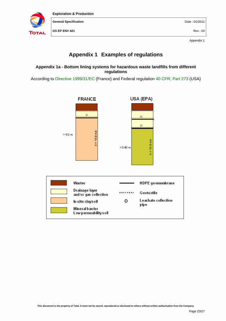
Appendix 1 Examples of regulations
Appendix 1a - Bottom lining systems for hazardous waste landfills from different regulations
According to Directive 1999/31/EC (France) and Federal regulation 40 CFR, Part 273 (USA)
Exploration & Production
General Specification Date : 01/2011
GS EP ENV 421 Rev : 03
Appendix 1
This document is the property of Total. It must not be stored, reproduced or disclosed to others without written authorisation from the Company.
Page 24/27
Appendix 1b - Bottom lining systems for non-hazardous and municipal waste landfills from different regulations
According to Directive 1999/31/EC (France) and Federal regulation 40 CFR, Part 273 (USA)
Exploration & Production
General Specification Date : 01/2011
GS EP ENV 421 Rev : 03
Appendix 1
This document is the property of Total. It must not be stored, reproduced or disclosed to others without written authorisation from the Company.
Page 25/27
Appendix 1c - Cover systems from different regulations According to Directive 1999/31/EC (France) and Federal regulation 40 CFR, Part 273 (USA)
Exploration & Production
General Specification Date : 01/2011
GS EP ENV 421 Rev : 03
Appendix 2
This document is the property of Total. It must not be stored, reproduced or disclosed to others without written authorisation from the Company.
Page 26/27
Appendix 2 Quality control
1. Mineral barrier Considering mineral barriers made by compacted soil layers, which are, at present, the most reliable parts of the containment system in the long and very long-term, it is possible to define, as in the following, the most important points with respect to achieving low hydraulic conductivity and good performance in general:
• Use of suitable materials
• Placement of the soil at the optimum water content
• Proper preparation of the surface to receive a lift of soil
• Soil compaction with adequate passage of the proper type of compactor
• Protection of each compacted lift from damage.
Certain key factors govern the full scale performance of mineral sealing layers, and these factors shall be checked during and after construction.
Company suggests the following tests and related frequencies for current QC of compacted soil barriers:
• Characteristics of the materials to be used, including grain size distribution, consistency limits, water intake and moisture content (every 1000 m2)
• Moisture content on placement, homogeneity of the placed material, number of passes of the compacting equipment, quantity of water added, if any (every 1000 m2)
• Minimum clod size, cutting depth and quantity of additives or dosage in the case of multiple components mixtures (every 1000 m2)
• Thickness of the individual lifts, evenness of the lift surfaces and adherence to proposed level and dimensions (every 500 m2)
• Degree of compaction and homogeneity achieved in the sealing layer or each lift by determination of density, moisture content, grain size distribution and plasticity if appropriate, and by topographic survey (every 1000 m2)
• Determination of the permeability of the sealing layer for each lift (every 2000 m2).
The visual observations on the number of passes of the compactor, the uniformity of the sealing materials and the degree of bonding with the upper part of the underlying lift are also very important to assure satisfactory field scale performance.
Density and water content are the key parameters from a statistical point of view to appreciate barrier hydraulic behavior. Hydraulic conductivity tests on small samples shall confirm the adequate compaction procedure given by measurements of water content and density.
The method to be used for the determination of hydraulic conductivity for landfills, in the field and over the totality of the site, is to be developed and approved by Company.
2. Leachate collection layer The efficiency of a leachate collection system has a very important effect in reducing the height of leachate ponding on the barrier and, consequently, the potential for advective migration. Therefore, careful design and high construction quality are mandatory in order to avoid failures, which are mainly due to different types of clogging phenomena. Construction details play a
Exploration & Production
General Specification Date : 01/2011
GS EP ENV 421 Rev : 03
Appendix 2
This document is the property of Total. It must not be stored, reproduced or disclosed to others without written authorisation from the Company.
Page 27/27
fundamental role in the final efficiency of the lining system in terms of field scale hydraulic conductivity.
Construction Quality Control (QC) testing is crucial to the successful performance of compacted soil liner and sand covers. Construction QC is designed to verify that:
• Materials used in construction are adequate
• The methods of construction are acceptable
• Liners and covers are adequately protected during and after construction.
The quality control of a drainage layer shall address the following points:
• Grain size distribution and mineralogical composition to avoid the presence of calcareous soils (one sample every 500 t)
• Topographical survey for the assessment of correct geometry in terms of slopes in the different directions (10 x 10 m grid); thickness check every 1000 m2
• Materials, thickness, opening geometry and structural resistance shall be checked on drainage pipes.
3. Liner placement The properties of geosynthetics may be affected by induced mechanical stresses, radiation, temperature, chemicals and micro-organisms.
On-site QC for geosynthetics placement shall address the following main aspects:
• Proper storage on-site
• Placement procedure
• Control after placement (inspection, possible repairs)
• Placement of the upper layer.
Compliance with relevant requirements should be demonstrated by suitability tests and both in-house and external construction QC tests.
Suitability tests include:
• Performance tests which allow products to be tested in conditions representative of the in-situ environment These tests are generally difficult to carry out, but they may be necessary for major projects
• Index tests representative of a the behavior of the products tested under standardized conditions (e.g.: tension, permeability); these tests are easier to perform
• Installation tests which characterize geotextiles under installation conditions; these tests also include the characterization of the physical properties of a product (e.g.: mass per unit area, thickness). These tests should be used in the QC plan to assist in the acceptance of the geotextiles on site.


![Trust the Process: How the NBA Can Combat Its “Tanking” … · 2019-03-31 · N3_PAXTON (DO NOT DELETE) 3/11/2019 3:35 PM 2019] HOW THE NBA CAN COMBAT ITS “TANKING” PROBLEM](https://static.documents.pub/doc/80x56/5fb8260837a0af1deb6f23ed/trust-the-process-how-the-nba-can-combat-its-aoetankinga-2019-03-31-n3paxton.jpg)

![arXiv:1610.00468v1 [cs.SD] 3 Oct 2016 · PDF filesheets. These schemes are based on guitar tablatures, and there is a wide list of software applications and libraries to handle digital](https://static.documents.pub/doc/80x56/5a76eec07f8b9aea3e8da4ea/arxiv161000468v1-cssd-3-oct-2016-a-sheets-these-schemes-are-based-on.jpg)