Exploration & Production This document is the property of Total. It must not be stored, reproduced or disclosed to others without written authorisation from the Company. GENERAL SPECIFICATION Design of Field Facilities GS EP SAF 253 Impacted area, restricted area and fire zones Main Instructor for Derogation: ECI (Design of Field Facilities) 04 10/2009 Sections 2, 3, 5, 6, 7, 8 and Appendix A updated 03 10/2008 Complete review and update 02 10/2005 Addition of Group name and logo 01 10/2003 Change of Group name and logo 00 04/2001 Old TotalFina SP SEC 253 Rev. Date Notes
Transcript
Exploration & Production
This document is the property of Total. It must not be stored, reproduced or disclosed to others without written authorisation from the Company.
GENERAL SPECIFICATION
Design of Field Facilities
GS EP SAF 253
Impacted area, restricted area and fire zones
Main Instructor for Derogation: ECI (Design of Field Facilities)
04 10/2009 Sections 2, 3, 5, 6, 7, 8 and Appendix A updated
03 10/2008 Complete review and update
02 10/2005 Addition of Group name and logo
01 10/2003 Change of Group name and logo
00 04/2001 Old TotalFina SP SEC 253
Rev. Date Notes
Exploration & Production
General Specification Date: 10/2009
GS EP SAF 253 Rev: 04
This document is the property of Total. It must not be stored, reproduced or disclosed to others without written authorisation from the Company.
Page 2/44
Contents
1. Scope .......................................................................................................................4 1.1 Purpose of the specification...............................................................................................4 1.2 Applicability........................................................................................................................4
3. Terminology and definitions ..................................................................................6
4. Main Principles and Requirements........................................................................9 4.1 General risk reduction philosophy .....................................................................................9 4.2 Hazardous scenarios .........................................................................................................9 4.3 Principle of application.......................................................................................................9 4.4 Criteria and thresholds.......................................................................................................9
5. General Approach ...................................................................................................9 5.1 Partition of an installation...................................................................................................9 5.2 Definition of Fire Zone, Restricted and Impacted Areas ..................................................10 5.3 General Methodology ......................................................................................................11
6. Specific aspects of fire zones ..............................................................................15 6.1 Partitioning criteria ...........................................................................................................15 6.2 Layout ..............................................................................................................................18 6.3 Relations with other concepts..........................................................................................20
7. Safety Distances ...................................................................................................21 7.1 General assumptions.......................................................................................................21 7.2 Fire zones ........................................................................................................................23 7.3 Restricted area ................................................................................................................24 7.4 Impacted area..................................................................................................................26 7.5 Summary table.................................................................................................................28
This document is the property of Total. It must not be stored, reproduced or disclosed to others without written authorisation from the Company.
Page 3/44
8.4 Toxic criteria ....................................................................................................................31 8.5 Flame emissive power for pool fires ................................................................................33 8.6 Boil over...........................................................................................................................33 8.7 Roof tank explosion .........................................................................................................33
Appendix A Criteria - Bibliographical references ..................................................35
Appendix B Leak discharge rate calculation..........................................................41
Appendix C Vapour Cloud Explosion (VCE) in units .............................................44
Exploration & Production
General Specification Date: 10/2009
GS EP SAF 253 Rev: 04
This document is the property of Total. It must not be stored, reproduced or disclosed to others without written authorisation from the Company.
Page 4/44
1. Scope
1.1 Purpose of the specification The purpose of this general specification is to define the safety requirements for the partition of an oil and gas production installation and the zone surrounding it into an Impacted Area, a Restricted Area and Fire Zones. This approach is aimed at fulfilling a two-fold objective:
• In accordance with API RP 14J hazard tree for production installations, and based upon unit layout, nature of equipment and risks (nature and level) associated to equipment, provide means or take dispositions that shall ensure:
o Prevention of ignition: Separate, as far as practicable, ignition sources from fuel sources
o Mitigation: Minimise the consequences of fires, explosions and other hazard; prevent escalation of fire to other areas; minimise hydrocarbon inventory in areas where fire initiated (isolation and depressurisation); focus active fire-fighting to one single zone and improve the emergency response; contain the risk within the boundaries of the installation and avoid exposure of public to hazards
o Escape, Evacuation and Rescue: Protect personnel from fire and explosion in the escape routes to a safe area
• Provide tools that will ensure the safety of public that may be present, either permanently or just passing by, in the vicinity of production facilities.
1.2 Applicability This specification is not retroactive; it applies to new installations and to major modifications or extensions of existing installations, both onshore and offshore. This specification is limited to the highlighting of functional requirements and safety related considerations; it does not cover, in particular:
• Equipment layout considerations, minimum distances and/or protection between equipment (refer to GS EP SAF 021)
• Hazardous areas definition (refer to GS EP SAF 216)
• Emergency shutdown and depressurisation systems (refer to GS EP SAF 261)
• Emergency Response (refer to GS EP SAF 371) and in particular Active Fire-Fighting (refer to GS EP SAF 311, GS EP SAF 321, GS EP SAF 322, GS EP SAF 331, GS EP SAF 334)
• Detailed design of the Passive Fire Protection systems (refer to GS EP SAF 337)
• Escape, Evacuation and Rescue procedures (refer to GS EP SAF 351)
• Underground pipelines.
2. Reference documents The reference documents listed below form an integral part of this General Specification. Unless otherwise stipulated, the applicable version of these documents, including relevant appendices and supplements, is the latest revision published at the EFFECTIVE DATE of the CONTRACT.
Exploration & Production
General Specification Date: 10/2009
GS EP SAF 253 Rev: 04
This document is the property of Total. It must not be stored, reproduced or disclosed to others without written authorisation from the Company.
Page 5/44
Standards
Reference Title
Not applicable
Professional Documents
Reference Title
API RP 14J Recommended Practice for Design and Hazards Analysis for Offshore Production Facilities
Regulations
Reference Title Circulaire du 23 Juillet 2007
Circulaire DPPR/SEI2/AL-07-0257 du 23/07/07 relative à l'évaluation des risques et des distances d’effets autour des dépôts de liquides inflammables et des dépôts de gaz inflammables liquéfiés. Annexe I Boil over note technique
Codes
Reference Title Not applicable
Other documents
Reference Title
Statement of Requirements
Safety Concept
Operating Philosophy
Site meteorological data
Exploration & Production
General Specification Date: 10/2009
GS EP SAF 253 Rev: 04
This document is the property of Total. It must not be stored, reproduced or disclosed to others without written authorisation from the Company.
Page 6/44
Total General Specifications
Reference Title
GS EP SAF 021 Lay-out
GS EP SAF 222 Safety rules for machinery and equipment handling hydrocarbon in enclosed areas
GS EP SAF 261 Emergency Shut-Down and Emergency De-Pressurisation (ESD & EDP)
GS EP SAF 262 Pressure protection relief and hydrocarbon disposal systems
GS EP SAF 321 Fire pump stations and fire water mains
GS EP SAF 334 Foam fire control systems
GS EP SAF 322 Fixed fire water systems
GS EP ECP 103 Process sizing criteria
3. Terminology and definitions There are three types of statements in this specification, the “shall”, “should” and “may” statements. They are to be understood as follows:
Shall Is to be understood as mandatory. Deviating from a “shall” statement requires derogation approved by the COMPANY
Should Is to be understood as strongly recommended to comply with the requirements of the specification. Alternatives shall provide a similar level of protection and this shall be documented
May Is used where alternatives are equally acceptable.
For the purpose of this specification, the following definitions shall apply (the terms defined in this section are often in bold characters in the text of the specification):
Active Fire-Fighting (AFF)
Any fire protection system or component which requires the manual or automatic detection of fire and which initiates a consequential response (API)
Credible event Incident likely to occur within a concerned area. Used for the definition of fire zones. Consequences corresponding to a credible event of a given fire zone shall not impact other fire zones (COMPANY)
Dose (toxic) A person exposed to a concentration C of a toxic gas during a period of time t inhales a toxic dose D = Cn x t where n is a constant specific to the substance considered. The value of D determines the level of harm the person will experience: lethality, intoxication, etc.
Exploration & Production
General Specification Date: 10/2009
GS EP SAF 253 Rev: 04
This document is the property of Total. It must not be stored, reproduced or disclosed to others without written authorisation from the Company.
Page 7/44
Emergency De-Pressurisation (EDP)
Control actions undertaken to depressurise equipment or process down to a pre-defined threshold (generally 7 barg or 50% of design pressure) in a given period of time (generally 15 minutes) in response to a hazardous situation (ISO + COMPANY)
Emergency Response (ER)
Action taken by personnel on or off the installation to control and/or mitigate a hazardous event (ISO)
Emergency Shutdown (ESD)
Control actions undertaken to Shutdown equipment or process in response to a hazardous situation (ISO)
Emergency Shutdown System (ESS)
System of manual stations and/or automatic devices which, when activated, initiate platform or facility shutdown (COMPANY)
Emergency Shutdown Valve (ESDV)
High integrity shutdown valve, handling a hazardous fluid or a fluid having an essential function, and located at the limit of a fire zone or within a fire zone to limit hydrocarbon inventory (COMPANY)
Fire and Gas (F&G) system
Safety system which monitors the temperature or the energy flux (fire), the concentration of flammable or toxic gases (gas), and initiates relevant actions (alarm, ESD, EDP active fire-fighting, electrical isolation, etc.) at pre-determined levels (COMPANY)
Fire zone Area within the installation where equipment is grouped by nature and/or homogeneous level of risk attached to them. The partition of an installation into fire zones results in a significant reduction of the level of risk. This implies that consequences of a fire, flammable gas leak or an explosion corresponding to the credible event likely to occur in the concerned fire zone, shall not impact other fire zones to an extent where their integrity could be put at risk (COMPANY)
Flammable atmosphere Mixture of flammable gas or vapour in air which will burn when ignited (ISO)
IDLH Immediately Dangerous to Life and Health: maximum concentration of a toxic substance to which an individual can be exposed during 30 minutes without experiencing irreversible effect to health (NIOSH and OSHA)
Impacted area Area that extends beyond the boundaries of the installation but which is nevertheless affected either permanently by normal operation of the facility (e.g. noise or radiation) or exceptionally by the consequences of an emergency situation caused by a major failure (COMPANY)
Ignition source Source of temperature and energy sufficient to initiate combustion (API)
Lethal Concentration (LCx%(y))
Atmospheric concentration which for a specified duration of exposure will cause the death of x% of an exposed population. The associated exposure is normally given e.g. LC1%(30) means 1% fatality after a 30-minute exposure (all applicable regulation)
Exploration & Production
General Specification Date: 10/2009
GS EP SAF 253 Rev: 04
This document is the property of Total. It must not be stored, reproduced or disclosed to others without written authorisation from the Company.
Page 8/44
Lower Flammable Limit (LFL)
Lower concentration of gas (by volume and expressed in percentage) in a gas-air mixture that will form an ignitable mixture (API, NFPA)
Major failure A conceivable incident that can possibly occur on the facility. Used for the definition of the facility restricted area and impacted area (COMPANY)
Mitigation Reduction of the effects of a hazardous event (ISO)
NIOSH National (US) Institute for Occupational Safety and Health
Normal operation Steady-state or transient, nominal or down-graded but staying within the facility initial design intention (COMPANY)
OSHA Occupational Safety and Health (US) Administration
Passive Fire Protection (PFP)
Coating, cladding arrangements or a free standing system which in the event of fire will provide thermal protection to the substrate to which it is attached or to the protected area (ISO)
Process Control System (PCS)
Controls the process and associated alarms. It does not fulfil a safety function and shall always be separated from other instrument systems fulfilling a safety function
Process Safety System (PSS)
Controls all causes/actions pertaining to SD-3 shutdowns (i.e. individual equipment), including fire and gas at local (equipment/package) level
Restricted area Area within the boundaries of the installation and hence under the control of COMPANY, affected permanently by normal operation of the facility or exceptionally by the consequences of an emergency situation caused by a major failure (COMPANY)
Shutdown Valve (SDV) Automatically operated, (generally fail to close) valve used for isolating a process station (API). SDV's are often referred to as Process Shutdown Valves (PSDV). The acronyms SDV and PSDV are equivalent but SDV shall be used in the present specification because SDV's are not always attached to a process system (COMPANY)
Source of release Point from which flammable gas, liquid or a combination of both can be released into the atmosphere (ISO)
Threshold Limit Value (TLV)
• Short Time Exposure Limit (STEL): used to quantify short term exposure of personnel to toxic gas (maximum of 4 exposures per day of less than 15 min each)
• Time Weighted Average (TWA): used to quantify continuous exposure of personnel to toxic gas (8 hours a day or 40 hours per week)
Units Division of the installation in a reasonable number of geographic and functional groups of equipment having the same type (hydrocarbon, pressure, inventory, ignition, etc.) and levels (high, medium, low) of risks (COMPANY).
Exploration & Production
General Specification Date: 10/2009
GS EP SAF 253 Rev: 04
This document is the property of Total. It must not be stored, reproduced or disclosed to others without written authorisation from the Company.
Page 9/44
4. Main Principles and Requirements
4.1 General risk reduction philosophy An underlying concept applied in the present General Specification is that distance is considered as the most efficient protection measure against the outcomes of hazardous scenarios.
4.2 Hazardous scenarios The list of applicable hazardous scenarios shall comprise events whose probability to occur and/or magnitude of outcomes have been deemed sufficiently high by COMPANY and/or Authorities having jurisdiction.
A typical list of applicable scenarios outcomes with their definitions is included in Section 5.3.2.
4.3 Principle of application The safety distances shall be calculated using the consequence based prescriptive approach developed further in this document.
Whenever specific project constraints make it impossible to apply the results of this approach, a risk assessment study is performed to check the acceptability of the design.
4.4 Criteria and thresholds For each retained hazardous scenario, based on established assumptions, calculations are carried out to determine safety distances related to given criteria such as:
• Level of flammability
• Radiation or thermal dose level (including solar radiation contribution)
• Overpressure
• Concentration of toxic compounds (toxic dose).
5. General Approach
5.1 Partition of an installation The layout and the partitioning (refer to Figure 1 - Typical layout - Fire zoning, restricted and impacted areas boundaries) of an oil and gas processing installation shall:
• Comply with the requirements imposed by consideration of safety within the installation itself
• Take into consideration risks resulting from industrial activity, either routine operation or abnormal event, to areas surrounding the facilities and population living there, if any.
The control of activities taking place within the installation is the responsibility of COMPANY. An area is determined in which only personnel authorized by COMPANY can be present. This area is called the restricted area.
The restricted area is further divided into fire zones.
Exploration & Production
General Specification Date: 10/2009
GS EP SAF 253 Rev: 04
This document is the property of Total. It must not be stored, reproduced or disclosed to others without written authorisation from the Company.
Page 10/44
The operation of the installation might however affect an area extending beyond the restricted area. This area is called the impacted area.
The discrimination between restricted and impacted areas also corresponds to the maximum prejudice that COMPANY's activities, either resulting from normal operation or from an incident, can cause to people:
• Outside the impacted area: People are not subject to any increased hazards than those inherent to any other human activities
• Inside the impacted area (but outside the restricted area): People might be subject to irreversible effects caused by a major failure of the installation. However, during normal plant operations, permanent prejudice to human beings is not expected
• Inside the restricted area: The consequences of an incident or from normal operation can be severe enough to cause permanent prejudice to human beings and shall therefore be off-limit to public.
FIRE ZONEIMPACT
DISTANCE
FIRE ZONE BOUNDARY
FIRE ZONEIMPACT
DISTANCE
FIRE ZONE BOUNDARY
RESTRICTEDAREA
BOUNDARY
PUBLIC(Personnel only)
RESTRICTEDAREA
BOUNDARY
PUBLIC(Personnel only)
PUBLIC(No restriction)
IMPACTEDAREA
BOUNDARY
PUBLIC(Not permanent)
PUBLIC(No restriction)
IMPACTEDAREA
BOUNDARY
PUBLIC(Not permanent)
IMPACTEDAREA
BOUNDARY
PUBLIC(Not permanent)
Figure 1 - Typical layout - Fire zoning, restricted and impacted areas boundaries
5.2 Definition of Fire Zone, Restricted and Impacted Areas
5.2.1 Fire zone Fire Zones are the areas within the installation where equipment are grouped by nature and/or homogeneous level of risk attached to them.
The partition of an installation into fire zones results in a significant reduction of the level of risk. This implies that consequences of a fire, flammable gas leak or an explosion corresponding to the credible event likely to occur in the concerned fire zone, shall not impact other fire zones to an extent where their integrity could be put at risk.
Exploration & Production
General Specification Date: 10/2009
GS EP SAF 253 Rev: 04
This document is the property of Total. It must not be stored, reproduced or disclosed to others without written authorisation from the Company.
Page 11/44
5.2.2 Restricted Area The Restricted Area is the area within the boundaries of the installation and hence under the control of COMPANY. The restricted area is affected:
• Permanently by normal operation of the facility
• Exceptionally by the consequences of an emergency situation caused by a major failure.
Within the restricted area, COMPANY shall have control of all possible sources of ignition, including vehicles (onshore) and vessels (offshore).
Onshore, a security fence shall include at least the restricted area. Offshore, the limits of the restricted area are to be shown on marine maps and may be materialised by buoys.
5.2.3 Impacted Area The Impacted Area is the area that extends beyond the boundaries of the installation but which is nevertheless affected either permanently by normal operation of the facility (e.g. noise or radiation) or exceptionally by the consequences of an emergency situation caused by a major failure.
The impacted area is not under the control of COMPANY but agreement shall be formalised with LOCAL AUTHORITIES to minimise presence of public (e.g. to limit construction of buildings, in particular permanent settlements, or operation of transportation means open to public).
The Emergency Response Plan and a Site Contingency Plan are set up by the COMPANY in collaboration with LOCAL AUTHORITIES to manage incidents and accidents within the impacted area. The Emergency Response Plan and the Site Contingency Plan may also cover areas extending beyond the impacted area but it is not the purpose of the present document to elaborate upon it.
5.3 General Methodology
5.3.1 Principle A deterministic approach is used to delimit fire zones, restricted and impacted areas.
A list of hazardous scenarios shall be established by performing a hazard identification (HAZID) study and selecting the appropriate scenarios outcomes from the Section 5.3.2 reference table. If necessary, relevant scenarios not contemplated in the reference table may be added.
The magnitude of the outcome resulting from the retained scenarios shall be established using models of consequence analysis validated by experience and/or by local regulation if more stringent.
A set of criteria (flammability limit, concentration of toxic compounds, radiation or thermal dose, overpressure) for maximum tolerable effects applicable to people and/or equipment shall be imposed.
The outcome of consequence analysis calculations provides distance envelopes defining for each case (onshore/offshore - fire zone/restricted area/impacted area), the corresponding safety distance or contour limit.
Exploration & Production
General Specification Date: 10/2009
GS EP SAF 253 Rev: 04
This document is the property of Total. It must not be stored, reproduced or disclosed to others without written authorisation from the Company.
Page 12/44
A calculation note shall be issued presenting selected scenarios outcomes, criteria used, assumptions taken and safety distance calculation results.
This calculation note shall be updated at each phase of the design of the installation (e.g. pre-project studies, project basic and detailed engineering). It shall also be updated during the operational phase if major change occurs (e.g. appearance of H2S, new neighbouring third party installations).
5.3.2 Scenarios outcomes definition The table below gives the definition of the main typical scenarios outcomes applicable to oil and gas production and processing installations.
Scenario outcome Definition
Un-ignited gas/spray cloud (flammable gas cloud or flammable atmosphere)
Mixture of flammable gas or vapour in air which will burn when ignited (ISO).
Un-ignited gas/spray cloud (toxic gas cloud)
Mixture of toxic gas or vapour in air (COMPANY).
Vapour Cloud Explosion in unit (VCE)
The explosion resulting from an ignition of a premixed cloud of flammable vapour, gas or spray with air, in which flames accelerate to sufficiently high velocities to produce significant overpressure (Yellow Book, TNO, 1997).
This type of explosion can occur in a confined enclosed unit or in a congested open unit (COMPANY).
Pool fire Combustion of flammable or combustible liquid spilled and retained on a surface (ISO).
Combustion of material evaporating from a layer of liquid at the base of the fire (UKOOA).
Jet fire The combustion of material emerging from an orifice with a significant momentum (UKOOA).
Ignited release of pressurised flammable fluids (ISO).
Boiling Liquid Expanding Vapour Explosion (BLEVE) & boil over
BLEVE: sudden rupture due to fire impingement of a vessel and/or system containing liquefied flammable gas under pressure; the pressure burst and the flashing of the liquid to vapour creates a blast wave and potential missile damage, and immediate ignition of the expanding fuel-air mixture leads to intense combustion creating a fireball (UKOOA) 1.
Boil over: expulsion of crude oil (or certain other liquids) from a burning tank. The light fractions of the crude oil burn off producing a heat wave in the residue, which on reaching a water stratum may result in the expulsion of a portion of the contents of the tank in the form of froth (OSHA).
Blowout When well pressure exceeds the ability of the wellhead valves to control it. Oil and gas “blow wild” at the surface (UKOOA).
1 It is caused by the reduction of the vessel metal strength due to heat competing with the increasing pressure of the liquefied
gases inside the vessel.
Exploration & Production
General Specification Date: 10/2009
GS EP SAF 253 Rev: 04
This document is the property of Total. It must not be stored, reproduced or disclosed to others without written authorisation from the Company.
Page 13/44
Scenario outcome Definition
Fixed roof tank explosion Confined explosion of a fuel-oxidant mixture inside a closed system such as vessel, module, etc. (UKOOA).
Flare normal operation Maximum Continuous Flaring (MCF): flaring the largest allowable steady flow of combustible gas in normal operating conditions (COMPANY).
Emergency Flaring (EF): flaring a peak flow of combustible gas in upset or emergency operating conditions (COMPANY).
Flare flame out: flammable and/or toxic
Unignited flare gas release.
Cold vents Vent handling significant flow rates generally from pressurised equipment. The word “cold” meaning without flame (COMPANY)2.
Degassing vents Vent handling low flowrates, generally from atmospheric equipment. A degassing vent is a non ignited vent (COMPANY)2.
LPG pool vaporisation Vaporisation of liquid LPG spilled and retained on a surface
2 The difference between "cold vent" and "degassing" vent are spelled out in details in GS EP SAF 262.
Exploration & Production
General Specification Date: 10/2009
GS EP SAF 253 Rev: 04
This document is the property of Total. It must not be stored, reproduced or disclosed to others without written authorisation from the Company.
Page 14/44
5.3.3 Application of scenarios outcomes The table below gives the different scenarios outcomes used to define distances between fire zones and to establish the contour limits of restricted and impacted areas of onshore and offshore installations.
Fire zone Restricted area Impacted area Un-ignited leak gas/spray/liquid
(LFL)
Un-ignited leak gas/spray/liquid (Toxic)
Jet fire gas/spray/liquid (Radiation)
Pool fire (Radiation)
VCE (Overpressure)
BLEVE and Boil over (Radiation)
Blow-out: un-ignited (LFL - Toxic),
Blow-out: un-ignited (Toxic),
Blow-out: ignited (Radiation)
Fixed roof tank explosion (Overpressure)
Flare flame out: continuous and emergency
(LFL - Toxic)
Flare flame out: continuous and emergency
(Toxic) Flaring normal operation:
continuous and emergency (Radiation - Toxic)
Flaring normal operation: continuous and emergency
(Radiation) Cold vents un-ignited:
emergency (LFL - Toxic)
Cold vents ignited: emergency (Radiation - Toxic)
Degassing vents un-ignited (LFL - Toxic)
Degassing vents ignited (Radiation)
LPG pool vaporisation (LFL)
Any other relevant scenario outcomes resulting from the HAZID study or imposed by local regulations
Exploration & Production
General Specification Date: 10/2009
GS EP SAF 253 Rev: 04
This document is the property of Total. It must not be stored, reproduced or disclosed to others without written authorisation from the Company.
Page 15/44
6. Specific aspects of fire zones In order to limit the consequences of the hazardous scenarios, COMPANY installations shall be partitioned into Fire Zones.
Separate fire zones are created in order to segregate hazards and limit the probability of escalation. Simultaneous independent hazardous scenarios in two separate fire zones shall not be considered (single jeopardy concept).
Fire zones should be as small as possible to increase safety, however the number of fire zones should be reduced in order to minimise the installation complexity. The partition into fire zones shall result from the optimum combination of these conflicting requirements, compounded with asset protection constraints.
6.1 Partitioning criteria
6.1.1 General The partition of an installation into fire zones is such that the consequences of a flammable gas leak, an explosion or a fire corresponding to the worst credible event likely to occur in the concerned fire zone shall not impact to other fire zones to an extent where their integrity could be put at risk.
The main principle adopted for the partition of the plant into fire zones is that it is not generally acceptable that a single credible event could result in the total loss of function of the plant.
The partition of an installation into fire zones shall be based on the combination of layout related considerations, functional independence between fire zones and homogeneity of risks presented by units (refer to GS EP SAF 021).
• Onshore: As a general rule, fire zones shall be separated by sufficient distance
• Offshore: As a general rule, fire zones shall coincide with platforms3. Certain platforms may be partitioned with more than one fire zone, provided there are efficient physical protections (e.g. sufficient distances, fire and/or blast walls) between two adjacent fire zones.
6.1.2 Safety systems To ensure the functional independence between fire zones, the F&G detection, its associated logics and the ESD logics shall be grouped by fire zone with corresponding ESDV's, BDV's and active fire-fighting systems.
6.1.3 Company's practice General specification GS EP SAF 021 and API RP 14J recommendations regarding compatibility of equipment shall be adhered to. In particular, the following units and equipment shall be located in different fire zones:
• Wellheads
• Liquefied hydrocarbon storage (refrigerated or under pressure)
3 In this context, the word platform includes all types of offshore structures (fixed and floating).
Exploration & Production
General Specification Date: 10/2009
GS EP SAF 253 Rev: 04
This document is the property of Total. It must not be stored, reproduced or disclosed to others without written authorisation from the Company.
Page 16/44
• Liquid hydrocarbon storage
• Process and utilities
• Buildings (e.g. living quarters, offices, workshops and warehouses and generally speaking the general service area)
• Hydrocarbon disposal systems (e.g. flares burn pits, cold vents, each type generating its own fire zone)
Typical fire zone partitions and installations layouts are given in Figure 2 - Offshore typical fire zone partitions and Figure 3 - Onshore typical fire zone partitions.
Fire zone buildings
Prevailing Wind
+
process / utilities
PROCESS
UTILITIES
Fire zone
Flare
WELL-HEADS
Fire zone well-heads
LIVING QUARTERS
OFFICES
CONTROL ROOM
WAREHOUSEWORKSHOP /
Blast proof / fire proof wall
Fire zone buildings
Prevailing Wind
PROCESS
Flare
UTILITIES WELL-HEADS
Fire zone well-heads
LIVING QUARTERS
OFFICES
CONTROL ROOM
process / utilitiesFire zone
WAREHOUSEWORKSHOP /
Figure 2 - Offshore typical fire zone partitions
Exploration & Production
General Specification Date: 10/2009
GS EP SAF 253 Rev: 04
This document is the property of Total. It must not be stored, reproduced or disclosed to others without written authorisation from the Company.
Page 17/44
Partition by trains:
SEPARATION COMPRESSION
Fire zone train 1
Fire zone train 2
Flare
UTILITIES
Fire zone utilities
TANK TANK
TANK TANK
Fire zone storage
LIV
ING
QU
ARTE
RS
Fire
zon
e bu
ildin
gs
Prevailing Wind
WORKSHOP
Fire zone buildings
WAREHOUSE
SEPARATION COMPRESSION
CONTROL ROOM
Fire zone buildings
OFFICES
Partition by units:
SEPARATION SEPARATION
Fire zone separation
Fire zone compression
Flare
UTILITIES
Fire zone utilities
TANK TANK
TANK TANK
Fire zone storage
LIVI
NG
QU
AR
TER
S
Fire
zon
e bu
ildin
gs
Prevailing Wind
WORKSHOP
Fire zone buildings
WAREHOUSE
COMPRESSION COMPRESSION
CONTROL ROOM
Fire zone buildings
OFFICES
Figure 3 - Onshore typical fire zone partitions
Exploration & Production
General Specification Date: 10/2009
GS EP SAF 253 Rev: 04
This document is the property of Total. It must not be stored, reproduced or disclosed to others without written authorisation from the Company.
Page 18/44
6.2 Layout
6.2.1 Size and shape The size of a fire zone shall be governed by COMPANY strategy regarding:
• The escalation prevention between fire zones in case of a single credible event (refer to Section 7.2)
• The benefit of train separation to preserve production availability.
The fire zone layout shall be designed taking into account the capabilities of the fire-fighting means (see GS EP SAF 321, GS EP SAF 322 & GS EP SAF 334), in particular:
• The maximum practical range of fire monitors, about 45 m for a standard flow of 120 m3/h
• The largest pool fire which can be extinguished with standard foaming agents, about 7000 m2.
Access and operation of a fire-fighting team shall be possible for any combination of fire scenario and weather conditions. In particular:
• Fire zones shall be convex and preferably rectangular
• External fire monitors shall be located away from the edge of the fire zone (see GS EP SAF 021)
• Onshore, the path between fire zones shall be straight and open at both ends.
6.2.2 Limits A fire zone is limited by (see Figure 4 - Fire zone limits):
• The edge of the installation, extending at least 1.5 m beyond the edge of the most peripheral equipment except ESDV's
• Passive protections such as fire and blast barriers (walls or decks)
• Dikes for onshore storage.
A fire zone can cover several elevations subject to specific risk evaluation (e.g. offshore integrated platforms).
Exploration & Production
General Specification Date: 10/2009
GS EP SAF 253 Rev: 04
This document is the property of Total. It must not be stored, reproduced or disclosed to others without written authorisation from the Company.
Page 19/44
Figure 4 - Fire zone limits
6.2.3 ESDV's The purpose of an ESDV associated to a fire zone is to protect this fire zone by avoiding that the hazardous inventory of the external system connected to the ESDV feeds an accident within the fire zone.
The ESDV shall be designed, located or protected so that a credible event within the fire zone it protects cannot create a failure of the ESDV itself or of its outboard connected piping. The inboard connecting piping shall be fully welded with the exception of the EDSV connecting flange and shall present no leak source.
Credible events within a fire zone shall not expose their associated ESDVs4 to levels greater than:
• A radiation of 15.9 kW/m2 (5000 BTU/hr/ft2), solar radiation included
• An overpressure of 300 mbar.
Two basic configurations may be envisaged:
• Configuration 1: one single ESDV is installed on the interconnection at sufficient distance of both fire zones to meet the radiation and overpressure criteria, such distance
4 By default, a distance of 15 m between an ESDV and its fire zone boundary shall be provided.
5000 BTU/hr/Sqft&
0.3 bar
1.5 m
1.5 m
1.5 m
Fire zone boundary
15m or
5000 BTU/hr/Sqft&
0.3 bar
15m or
1.5 m
Exploration & Production
General Specification Date: 10/2009
GS EP SAF 253 Rev: 04
This document is the property of Total. It must not be stored, reproduced or disclosed to others without written authorisation from the Company.
Page 20/44
being possibly reduced if additional protections of the ESDV and its connected piping are provided (see Figure 5 - Interconnection between fire zones. Configuration 1)
• Configuration 2: two ESDV’s are installed to reduce distances and/or to avoid existence of "isolated" ESDV's. One ESDV protecting a fire zone is located at the limit of the adjacent fire zone and vice-versa. In that case, the interconnecting piping between ESDV’s shall be provided with depressurisation facilities in accordance with the requirements of GS EP SAF 261 (see Figure 5 - Interconnection between fire zones. Configuration 2).
Figure 5 - Interconnection between fire zones (Configurations 1 & 2)
6.3 Relations with other concepts
6.3.1 Emergency Shutdown (ESD) and Emergency Depressurisation (EDP) A fire zone coincides exactly with an "ESD-1 zone" and therefore all ESD and EDP aspects shall follow the requirements of GS EP SAF 261.
6.3.2 Deluge Where a deluge system is installed, a fire zone coincides exactly with a "deluge zone".
This deluge zone can be broken down into several "sub-deluge zones" when:
• the reduction of the fire water demand becomes paramount and/or
IN
FIRE ZONE 1(Receiving facilities)
FIRE ZONE 2(Process)
BDV
FIRE ZONE 1ESDV
IN
FIRE ZONE 1(Receiving facilities)
FIRE ZONE 2(Process)
ESDVOUTLET
Configuration 1
ESDVINTER
FIRE ZONE
ESDVINTLET
OU
TO
UT
FLAR
E
ESDVOUTLET
Configuration 2
*
*If required as per GS EP SAF 261
*
FIRE ZONE 2ESDV
ESDVINTLET
Exploration & Production
General Specification Date: 10/2009
GS EP SAF 253 Rev: 04
This document is the property of Total. It must not be stored, reproduced or disclosed to others without written authorisation from the Company.
Page 21/44
• it is imperative to reduce damages to equipment (hot equipment, machinery, effect of seawater) located far enough from the fire and that would suffer from deluge.
A sub-deluge zone is part of one, and only one, deluge zone and cannot sit over two deluge zones.
Dividing a deluge zone into several sub-deluge zones is acceptable providing that:
• Deluge can be activated simultaneously in the concerned sub-deluge zone and in the adjacent sub-deluge zones deemed at risk by the result of a fire risk analysis
• All hydrocarbon lines, running from the concerned sub-deluge zone to a sub-deluge zone beyond the adjacent sub-deluge zones, are fitted with ESDVs protected against fire and explosion.
The maximum fire water demand may then be limited to the most demanding case by evaluating the consequences of a fire in all sub-deluge zones.
7. Safety Distances
7.1 General assumptions
7.1.1 Design bases for Fire Zone Fire zones contours shall be based on consequences resulting from credible events.
7.1.1.1 Credible event definition A credible event can be described as the incident likely to occur within the concerned area, considering equipment type, nature of process fluid(s), hydrocarbon inventory, process characteristics (e.g. pressure and temperature) and the mode of operation.
Credible events specified in Section 7.2 are defined by COMPANY experience; however, more stringent assumptions may need to be taken into consideration if imposed by local regulations.
7.1.1.2 ESD, EDP and active fire-fighting The fire zone impact contours shall be designed assuming that Emergency Shutdown, Emergency Depressurisation Systems and fixed fire fighting means are out of service.
When the fixed fire-fighting appliances do operate satisfactorily, they shall strive to prevent the hazard from extending within the concerned fire zone but in no case they can be taken into consideration to mitigate impact of one hazard onto an adjacent fire zone.
Therefore fixed fire-fighting means, along with adequate dispositions regarding equipment lay-out, shall be designed to fulfil the protection requirements internal to one fire zone and shall not be considered as an input parameter that may alter fire zone impact contour.
7.1.2 Design bases for Restricted and Impacted Areas Restricted Area and Impacted Area contours determination shall consider both normal operation conditions and major failures.
Exploration & Production
General Specification Date: 10/2009
GS EP SAF 253 Rev: 04
This document is the property of Total. It must not be stored, reproduced or disclosed to others without written authorisation from the Company.
Page 22/44
7.1.2.1 Normal operation definition Normal operations consist of all operating configurations or modes, either steady-state or transient, nominal or down-graded, staying within the facility initial design intention.
Plant normal operation is kept under control of the various supervisory systems (PCS, PSS, ESD, F&G). Any situation which occurs when an operating parameter ranges outside of its normal pre-established limits can be quickly returned within design basis and without further damage to the installation.
7.1.2.2 Major failure definition A major failure can be described as a conceivable incident that can possibly occur on the facility, selected out of a list of reference incidents based on experience and considering that mitigation measures have been implemented and protection systems have operated as required.
Major failures specified in Sections 7.3 and 0 are defined by COMPANY experience; however, more stringent assumptions may need to be taken into consideration if imposed by local regulations.
7.1.2.3 ESD, EDP and active fire-fighting The restricted and impacted areas contours shall be designed assuming that Emergency Depressurisation System and fixed fire-fighting means are out of service.
The contours shall be evaluated assuming that the fuel source is cut-off after a response time equal to:
• 90 seconds if two automatic shutdown valves isolate the leak from the hydrocarbon inventory
• Otherwise 10 minutes5.
5 COMPANY considers that 10 minutes corresponds to the time for the consequence of the release to be stabilised and/or to
manually cut off the fuel source.
Exploration & Production
General Specification Date: 10/2009
GS EP SAF 253 Rev: 04
This document is the property of Total. It must not be stored, reproduced or disclosed to others without written authorisation from the Company.
Page 23/44
7.2 Fire zones The table below indicates the scenarios, main input data (based on retained credible events) and criteria applicable to establish the fire zone safety distances.
Effect Scenario Specific conditions Criteria
Un-ignited flammable gas/spray cloud dispersion from gas/ two-phase or liquid release
• 20 mm (1) leak diameter
• Initial release rate for 10 minutes • Release height 1 m • Horizontal jet and horizontal-
impacted jet Flammability
Liquid pool vaporisation (LPG only)
• Size of retention basin or 20 mm (1) leak diameter (spreading pool)
• 20 mm (1) leak diameter • Initial release rate for 10 minutes
• Release height 1 m • Horizontal jet
Thermal radiation
Pool fire in retention basin • Size of retention basin
9.5 kW/m2 (2)
Overpressure Vapour cloud explosion (VCE) in unit
• Unit volume half full of flammable gas at stoichiometric concentration 200 mbar
(1) Corresponds approximately to the full bore rupture of a 1” pipe diameter
(2) Including solar radiation
Exploration & Production
General Specification Date: 10/2009
GS EP SAF 253 Rev: 04
This document is the property of Total. It must not be stored, reproduced or disclosed to others without written authorisation from the Company.
Page 24/44
7.3 Restricted area The table below indicates the scenarios, main input data (based on retained major failures) and criteria applicable to establish the restricted area contour limit.
Effect Scenario Specific conditions Criteria
Flammability
Un-ignited flammable gas/spray cloud dispersion from gas/ two-phase or liquid release
• Leak diameter vs. pipe diameter: 0.20 pipe diameter limited to a minimum leak size of 20 mm and a maximum leak size of 150 mm
• Average release rate or release rate vs. time
• Release height 1 m • Horizontal jet and horizontal-impacted
jet
LFL
Toxicity Un-ignited toxic gas/spray cloud dispersion from gas/ two-phase or liquid release
• Leak diameter vs. pipe diameter: 0.20 pipe diameter limited to a minimum leak size of 20 mm and a maximum leak size of 150 mm
• Average release rate or release rate vs. time
• Release height 1 m • Horizontal jet and horizontal-impacted
jet
Toxic gas LC1%
Jet fire from gas, two-phase or liquid release
• Leak diameter vs. pipe diameter: 0.20 pipe diameter limited to a minimum leak size of 20 mm and a maximum leak size of 150 mm
• Average release rate or release rate vs. time
• Release height 1 m
• Horizontal jet
Pool fire in retention basin • Size of retention basin
Degasing vent – normal operation (ignited)
• Maximum continuous flow rate • Release direction according to the tip
direction
4.7 kW/m2 (1)
Flare - emergency operation (ignited)
• Emergency flow rate • Release direction according to the tip
direction
• 4.7 kW/m2 (1) • Toxic gas TLV
STEL
Flare - continuous operation (ignited)
• Maximum continuous flow rate • Release direction according to the tip
direction
• 3.2 kW/m2 (1) • Toxic gas TLV
TWA
BLEVE • Volume of liquid under pressure in sphere or bullet
Thermal radiation or Thermal dose
Boil over (2) • Tank liquid volume 1000 (kW/m2)4/3.s
(1) Including solar radiation
(2) Specific to onshore installations
Exploration & Production
General Specification Date: 10/2009
GS EP SAF 253 Rev: 04
This document is the property of Total. It must not be stored, reproduced or disclosed to others without written authorisation from the Company.
Page 25/44
Effect Scenario Specific conditions Criteria
Vapour cloud explosion (VCE) in unit
• Unit volume full of flammable gas at stoichiometric concentration Overpressure
Roof tank explosion • Refer to Section 8.7. 140 mbar
Flare flame out • Continuous and emergency flow rate • Release direction according to the tip
• Emergency flow rate • Release direction according to the tip
direction
• LFL • Toxic gas TLV
STEL
Degassing vent - normal operation (un-ignited)
• Maximum continuous flow rate • Release direction according to the tip
direction
• LFL • Toxic gas TLV
TWA
Flammability & toxicity
Blow out (un-ignited release)
• Tubing diameter • Release rate according tubing
diameter and well conditions
• Vertical jet
• LFL • Toxic gas LC1%
Cold vent - emergency operation (ignited release)
• Emergency flow rate • Release direction according to the tip
direction
• Toxic gas LC1% • 4.7 kW/m2 (1)
Thermal radiation & toxicity
Blow out (ignited release)
• Tubing diameter • Release rate according tubing
diameter and well conditions
• Vertical jet
• Toxic gas LC1% • 4.7 kW/m2 (1)
(1) Including solar radiation
Exploration & Production
General Specification Date: 10/2009
GS EP SAF 253 Rev: 04
This document is the property of Total. It must not be stored, reproduced or disclosed to others without written authorisation from the Company.
Page 26/44
7.4 Impacted area The table below indicates the scenarios, main input data (based on retained major failures) and criteria applicable to establish the impacted area contour limit.
Effect Scenario Specific conditions Criteria
Un-ignited toxic gas/spray cloud dispersion from gas/ two-phase or liquid release
• Leak diameter vs. pipe diameter: 0.20 pipe diameter limited to a minimum leak size of 20 mm and a maximum leak size of 150 mm
• Average release rate or release rate vs. time
• Release height 1 m • Horizontal jet and and horizontal-
impacted jet
Blow out (un- ignited release)
• Tubing diameter • Release rate according tubing
diameter and well conditions
• Vertical jet
Toxicity
Flare flame out
• Continuous and emergency flow rate
• Release direction according to the tip direction
Toxic gas IDLH
Jet fire from gas, two-phase or liquid release
• Leak diameter vs. pipe diameter: 0.20 pipe diameter limited to a minimum leak size of 20 mm and a maximum leak size of 150 mm
• Average release rate • Release height 1 m
• Horizontal jet
Pool fire in retention basin • Size of retention basin
3.2 kW/m2 (1)
Flare - emergency operation (ignited)
• Emergency flow rate • Release direction according to
the tip direction
Degassing vent – normal operation (ignited)
• Maximum continuous flow rate • Release direction according to
the tip direction
2.0 kW/m2 (1)
Flare - continuous operation (ignited)
• Maximum continuous flow rate • Release direction according to
the tip direction 1.6 kW/m2 (1)
BLEVE • Volume of liquid under pressure in sphere or bullet
Thermal radiation or Thermal dose
Boil over (2) • Tank liquid volume 600 (kW/m2)4/3.s
Exploration & Production
General Specification Date: 10/2009
GS EP SAF 253 Rev: 04
This document is the property of Total. It must not be stored, reproduced or disclosed to others without written authorisation from the Company.
Page 27/44
Effect Scenario Specific conditions Criteria
Vapour cloud explosion (VCE) in unit
• Unit volume full of flammable gas at stoichiometric concentration Overpressure
Roof tank explosion • Refer to Section 8.7. 50 mbar
Cold vent - emergency operation (ignited release)
• Emergency flow rate • Release direction according to
the tip direction
• Toxic gas IDLH • 2.0 kW/m2 (1)
Toxicity & thermal radiation
Blow out (ignited release)
• Tubing diameter • Release rate according tubing
diameter and well conditions
• Vertical jet
• Toxic gas IDLH
• 3.2 kW/m2 (1)
(1) Including solar radiation
(2) Specific to onshore installations
Exploration & Production
General Specification Date: 10/2009
GS EP SAF 253 Rev: 04
This document is the property of Total. It must not be stored, reproduced or disclosed to others without written authorisation from the Company.
Page 28/44
7.5 Summary table The table below includes for each selected scenario the criteria for determining fire zone, restricted and impacted areas.
Scenario Criteria fire zone
Criteria restricted area
Criteria impacted area
Un-ignited flammable gas/spray cloud dispersion from gas/2-phase or liquid release
LFL LFL NR
Un-ignited toxic gas/spray cloud dispersion from gas/2-phase or liquid release
NR Toxic gas LC1% Toxic gas IDLH
Jet fire from gas, 2-phase or liquid release 9.5 kW/m2 (1) 4.7 kW/m2 (1) 3.2 kW/m2 (1)
Pool fire in retention basin 9.5 kW/m2 (1) 4.7 kW/m2 (1) 3.2 kW/m2 (1) Liquid pool vaporization (LPG only) LFL NR NR Vapor cloud explosion (VCE) in unit 200 mbar 140 mbar 50 mbar BLEVE NR 1000 (kW/m2)4/3.s 600 (kW/m2)4/3.s Roof tank explosion NR 140 mbar 50 mbar Boil over (2) NR 1000 (kW/m2)4/3.s 600 (kW/m2)4/3.s
Flare flame out (3) NR LFL Toxic gas LC1% Toxic gas IDLH
Cold vent - emergency operation (un-ignited release) (3) NR LFL
Toxic gas TLV STEL NR
Cold vent - emergency operation (Ignited release) (3) NR Toxic gas LC1%
4.7 kW/m2 (1) Toxic gas IDLH 2.0 kW/m2 (1)
Degassing vent - normal operation (un-ignited release) NR LFL
Toxic gas TLV TWA NR
Degassing vent - normal operation (ignited release) NR 4.7 kW/m2 (1) 2.0 kW/m2 (1)
Blowout (un-ignited release) NR LFL
Toxic gas LC1% Toxic gas IDLH
Blowout (ignited release) NR Toxic gas LC1%
4.7 kW/m2 (1) Toxic gas IDLH 3.2 kW/m2 (1)
(1) Including solar radiation
(2) Specific to onshore installations
(3) Flares and cold vents should be located outside other units flammable gas restricted areas and conversely other units should be located outside the restricted area generated by flares and cold vents
NR: Not Relevant
Exploration & Production
General Specification Date: 10/2009
GS EP SAF 253 Rev: 04
This document is the property of Total. It must not be stored, reproduced or disclosed to others without written authorisation from the Company.
Page 29/44
8. Modelling calculations specifics All modelling calculations input parameters shall be validated by COMPANY at the beginning of the study prior to any calculation.
8.1 Softwares PHAST software from DNV shall be the preferred tool used for consequence modelling (dispersion, radiation and BLEVE).
CAM2 from FRED software should be used for congested open units explosion modelling. Otherwise, the TNO multi-energy method may be used in accordance with the methodology developed in Appendix C.
Computational Fluid Dynamics (CFD) softwares may be used to determine complex dispersion, radiation and explosion, subject to the approval of COMPANY.
CFD softwares shall be used for confined enclosed units explosion modelling.
FLARESIM software shall be used for flare and ignited vent radiation modelling in accordance with the requirements of GS EP ECP 103.
8.2 Meteorological conditions Meteorological conditions input data generally have a great influence on the calculated safety distances. The meteorological conditions are mainly governed by:
• Wind speed and atmospheric stability (thermal turbulence of the atmosphere)
• Surface roughness (mechanical turbulence of the atmosphere)
• Atmospheric and Ground/Water temperatures
• Relative humidity
• Solar radiation.
8.2.1 Wind speed and atmospheric stability Some of these parameters may vary during the day. The average data used for calculation shall be representative of the specific site meteorological conditions and in compliance with the local regulation.
Nevertheless, extreme meteorological conditions for specific scenario shall be considered (for instance arctic conditions, high ambient temperature or low relative humidity).
It is recommended to analyse site specific data if available. If no meteorological data are available for the site, the following sets of meteorological conditions shall be considered by default:
• D2 to D20, “D” being the neutral atmospheric condition with wind speed varying from 2 m/s to 20 m/s (it is recommended to consider D2, D3, D5, D8, D10, D15 and D20 conditions)
• F2, “F” being the very stable atmospheric condition with low wind speeds (onshore only).
Exploration & Production
General Specification Date: 10/2009
GS EP SAF 253 Rev: 04
This document is the property of Total. It must not be stored, reproduced or disclosed to others without written authorisation from the Company.
Page 30/44
8.2.2 Surface roughness Surface roughness shall be by default:
• 1 m for industrial area (roughness parameter 0.17)
• 0.2 m for flat terrain (roughness parameter 0.11)
• 0.013 m for sea/water surface (roughness parameter 0.06).
Note that surface roughness is to be defined, taking into account the nature of the terrain up to several kilometres upstream of the release location.
8.2.3 Atmospheric and ground/water temperatures By default, ground temperature shall be assumed equal to atmospheric temperature.
Site specific average atmospheric temperature shall be considered.
If no data is available, ambient temperature shall be:
• For temperate areas
o 20°C for the ‘D’ conditions
o 10°C for the ‘F’ conditions.
• For tropical/equatorial areas
o 30°C for the ‘D’ conditions
o 20°C for the ‘F’ conditions.
8.2.4 Relative humidity Site specific average relative humidity shall be considered.
If no data is available, relative humidity shall be taken equal to 70% for temperate areas and 90% for tropical/equatorial areas.
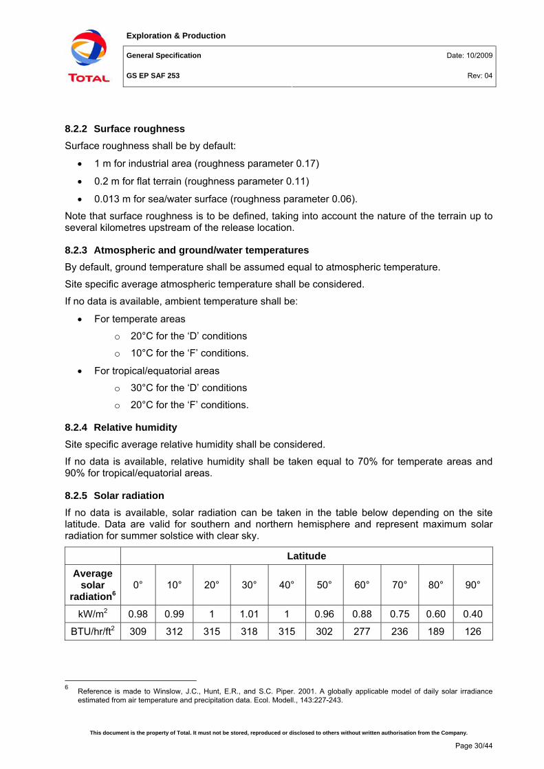
8.2.5 Solar radiation If no data is available, solar radiation can be taken in the table below depending on the site latitude. Data are valid for southern and northern hemisphere and represent maximum solar radiation for summer solstice with clear sky.
6 Reference is made to Winslow, J.C., Hunt, E.R., and S.C. Piper. 2001. A globally applicable model of daily solar irradiance
estimated from air temperature and precipitation data. Ecol. Modell., 143:227-243.
Exploration & Production
General Specification Date: 10/2009
GS EP SAF 253 Rev: 04
This document is the property of Total. It must not be stored, reproduced or disclosed to others without written authorisation from the Company.
Page 31/44
8.3 "Source term" evaluation
8.3.1 Definition “Source term” evaluation is the determination of the flowrate, the velocity, the temperature, the liquid fraction and the droplets diameter of a release from a gaseous, liquid or diphasic hydrocarbon and/or toxic mixture at a given source pressure and temperature.
8.3.2 Fire zone A release duration of 10 minutes shall be considered during which the release flowrate shall be considered constant and equal to the initial release rate through a 20 mm diameter release.
8.3.3 Restricted and impacted areas
8.3.3.1 Gas mixture Release flowrate shall be determined versus time in compliance with the requirements of Appendix B or with adequate softwares, which are subject to COMPANY approval.
Should the consequence modelling software not take into account the time-varying release, then an average release rate shall be calculated considering one or several segments depending on the shape of the flowrate versus time curve.
Fluid pressure is then adjusted in the software to re-produce the average release rate and obtain the characteristics (e.g. velocity, temperature or liquid fraction) of the ‘averaged’ release.
8.3.3.2 Liquid and diphasic mixture Release flowrate should be calculated versus time, using adequate softwares, subject to sound engineering judgement and in agreement with COMPANY.
If the calculation of the release flowrate versus time cannot be performed due to software limitations, then the following method shall be applied:
• Initial release flowrate is calculated using operating fluid conditions and leak size as defined in Sections 7.3 and 0
• Should the initial release flowrate be greater than the normal operating flowrate, then the leak size is adjusted in the software to re-produce an initial release flowrate equal to the normal operating flowrate
• The leak flowrate is assumed to be constant over the whole release duration period
• In the case of a diphasic release, a flash calculation of the hydrocarbon mixture in isentropic conditions is performed. Then, the vapour phase and the aerosol part of the liquid phase are taken into account for the dispersion modelling.
8.4 Toxic criteria
8.4.1 Toxicity of single gaseous substance The effect of the inhalation of a toxic substance is a function of concentration and of exposure time which may be expressed by the relation:
tCL n=
Exploration & Production
General Specification Date: 10/2009
GS EP SAF 253 Rev: 04
This document is the property of Total. It must not be stored, reproduced or disclosed to others without written authorisation from the Company.
Page 32/44
where
• L is the toxic load or toxic dose (ppmn.min)
• C is the concentration of the toxic substance (ppm)
• t is the exposure time (min)
• n is a constant describing the toxicity of a substance
The considered toxic thresholds (C in ppm) are the LCx%(30), the IDLH and the TLV (definitions given in Section 3).
Threshold values shall comply with local regulation. Current values at the time of the writing of the present specification are given in Appendix A.
To convert a “ppm” value in a “mg/m3” value, the following equation shall be used:
ppmmmgCMC
45.243/= (at 20 °C and Patm)
where
• M is the molecular weight of the toxic substance (kg/kmol)
• Cmg/m3 is the concentration of the toxic substance(mg/m3)
• Cppm is the concentration of the toxic substance (ppm volume)
Toxic loads (L in ppmn.min) are given in Appendix A for some toxic substances.
If the toxic load is not available, IDLH and LC1% for another exposure time may be estimated using the following equation:
2n
21n
1 t.Ct.CL == (Haber’s law)
where:
• L is the toxic load or toxic dose (ppmn.min)
• Ci is the concentration of toxic in air (ppm)
• ti is the exposure time (min)
• n is a specific coefficient of the toxic substance (current values at the time of the writing of the present specification are given in Appendix A).
If the specific coefficient "n" is unknown, a value of 2 shall be used by default.
8.4.2 Toxicity of mixed gaseous substances The equivalent toxic threshold of a gaseous mixture containing several toxic substances which have similar types of toxics effects may be estimated for a given exposure time with the following equation:
∑=i iTOX
i
EQTOX tCX
tC )()(1
Exploration & Production
General Specification Date: 10/2009
GS EP SAF 253 Rev: 04
This document is the property of Total. It must not be stored, reproduced or disclosed to others without written authorisation from the Company.
Page 33/44
where
• CTOXEQ (t) is the toxic threshold of the mixture for a given exposure time (ppm)
• Xi is the molar concentration of the component “i” in the mixture
• CTOX i (t) is the toxic threshold of the component for a given exposure time (ppm).
8.5 Flame emissive power for pool fires The maximum emissive power (at the surface of the flame) shall be:
• 30 kW/m2 for crude oil and condensate
• 100 kW/m2 for LPG
• 165 kW/m2 for LNG.
8.6 Boil over By default, the boil over shall be calculated as per mentioned in the French Circulaire du 23 juillet 2007 relative à l’évaluation des risques et des distances d’effets autour des dépôts de liquide inflammable et des dépôts de gaz inflammables liquéfiés. Annexe I Boil over note technique. Alternative method can be accepted subject to COMPANY approval.
8.7 Roof tank explosion By default, the roof tank explosion shall be calculated as per formula7 provided below. Alternative method can be accepted subject to COMPANY approval.
Tanks with ratio « r » less or equal to 1
Overpressure (mbar)
Pressure wave distance (m)
50 d50 = 4.848
140 d140 = 2.238
170 d170 = 1.958
200 d200 = 1.678
. [ DEQU² . HEQU ] (1/3)
7 Reference to « Modélisation des effets de surpression dus à une explosion de bac atmosphérique » of the GTDLI (Groupe de
Travail Dépôts de Liquides Inflammables), version May 2006
Exploration & Production
General Specification Date: 10/2009
GS EP SAF 253 Rev: 04
This document is the property of Total. It must not be stored, reproduced or disclosed to others without written authorisation from the Company.
Page 34/44
Tanks with ratio « r » above 1
Overpressure (mbar)
Pressure wave distance (m)
50 d50 = 6.107
140 d140 = 2.797
170 d170 = 2.471
200 d200 = 2.098
. [ DEQU² . HEQU ] (1/3)
where
• r = HEQU / DEQU
• HEQU : Tank height (metres)
• DEQU : Tank diameter (metres)
• dxx is measured from the centre of the tank and is rounded up to the next highest multiple of five (e.g. 103m to be rounded up to 105m)
Exploration & Production
General Specification Date: 10/2009
GS EP SAF 253 Rev: 04
Appendix A
This document is the property of Total. It must not be stored, reproduced or disclosed to others without written authorisation from the Company.
Page 35/44
Appendix A Criteria - Bibliographical references
Regulations
Reference Title TNO - Yellow book Methods for the calculation of physical effects (PGS 2 - CPR 14E)
Circulaire du 31 Janvier 2007
Circulaire DPPR/SEI2/AL- 06- 357 du 31/01/07 relative aux étude de dangers des dépôts de liquides inflammables - Compléments à l'instruction technique du 9 novembre 1989 Includes « Modélisation des effets de surpression dus à une explosion de bac atmosphérique » of the GTDLI (Groupe de Travail Dépôts de Liquides Inflammables) and « Evaluation des effets de surpression dus à une explosion de bac atmosphérique » worksheet
Heat fluxes
Radiation level (1) Damage to people Damage to asset
11 900 BTU/hr/ft2 (37.5 kW/m2)
Immediate pain threshold (2) Minimum lethal flux in 8 s (2)
Possible fire transfer to cooled tanks (3) Sufficient to cause damage to process equipment. Minimum energy required to ignite wood at indefinitely long exposures (4) Collapse of metallic framework buildings in 10 min (8)
6300 BTU/hr/ft2 (20 kW/m2)
Seuil de tenue du béton pendant plusieurs heures et correspondant au seuil des dégâts très graves sur les structures béton (10)
5000 BTU/hr/ft2 (15.8 kW/m2)
Pain threshold limit in less than 3 s (5) Seuil (16 kW/m2) d'exposition prolongée des structures et correspondant au seuil des dégâts très graves sur les structures, hors structures béton (10)
4000 BTU/hr/ft2 (12.5 kW/m2)
Pain threshold limit in about 3 s (5) Minimum lethal flux in 30 s (2)
No probable fire transfer to cooled tanks (3) Sufficient to cause damage for buildings (4) Minimum energy required for piloted ignition of wood, melting of plastic tubing Sufficient for wood to ignite after prolonged exposure (6)
Exploration & Production
General Specification Date: 10/2009
GS EP SAF 253 Rev: 04
Appendix A
This document is the property of Total. It must not be stored, reproduced or disclosed to others without written authorisation from the Company.
Page 36/44
Radiation level (1) Damage to people Damage to asset
3000 BTU/hr/ft2 (9.5 kW/m2)
Pain threshold limit in 6 s (3) (5) 2nd degree burns after 20 s (4) Minimum lethal flux in 60 s (3)
Maximum radiant heat intensity at any location where urgent emergency action by personnel is required. When personnel enter or work in an area with the potential for radiant heat intensity greater than 6.31 kW/m2, then radiation shielding and/or special protective apparel (e.g. a fire approach suit) to be considered. It is important to recognise that personnel with appropriate clothing cannot tolerate thermal radiation at 6.31 kW/m2 for more than a few seconds (5)
Exposed structures must be protected if exposition duration is more than 1 hour (9)
2500 BTU/hr/ft2 (8 kW/m2)
Seuil des effets létaux significatifs délimitant la « zone des dangers très graves pour la vie humaine » (10)
Initiation of wood and paint auto-combustion. No probable fire transfer to uncooled tanks. Fire fighting with special protection (3)
Seuil des effets domino et correspondant au seuil de dégâts graves sur les structures (10)
2000 BTU/hr/ft2 (6.3 kW/m2)
Pain threshold reached in 8 s and blistering in 20 s (5)
Maximum radiant heat intensity in areas where emergency actions lasting up to 30 s can be required by personnel without shielding but with appropriate clothing (5)
1500 BTU/hr/ft2 (4.7 kW/m2)
Pain threshold limit in 16 s (5) Minimum lethal flux in 60 s (7)
Maximum radiant heat intensity in areas where emergency actions lasting 2 min to 3 min can be required by personnel without shielding but with appropriate clothing (5)
Seuil (5 kW/m2) des effets létaux délimitant la « zone des dangers graves pour la vie humaine » (10)
Window glass breaking by thermal effect (3)
Seuil (5 kW/m2) des destructions de vitres significatives (10)
1000 BTU/hr/ft2 (3.2 kW/m2)
Pain threshold limit in less than 30 s (5) Significant burns threshold in 60 s (7) Minimum lethal flux in 120 s (3)
Seuil (3 kW/m2) des effets irréversibles délimitant la « zone des dangers significatifs pour la vie humaine » (10)
Exploration & Production
General Specification Date: 10/2009
GS EP SAF 253 Rev: 04
Appendix A
This document is the property of Total. It must not be stored, reproduced or disclosed to others without written authorisation from the Company.
Page 37/44
Radiation level (1) Damage to people Damage to asset
550 BTU/hr/ft2 (1.74 kW/m2)
Pain threshold reached in 60 s (5)
Maximum radiant heat intensity at any location where personnel with appropriate clothing can be continuously exposed (5)
(1) Solar radiation included (300 BTU/hr/ft2 or 0.95 kW/m2 by default)
(2) Source: Company Guide GM-SAF-013
(3) Source: GESIP
(4) Source: "Guidelines for Evaluating the Characteristics of Vapor Cloud Explosions, Flash Fires and BLEVEs" - Centre for Chemical Process Safety, Year 1994
(5) Source: API STD 521
(6) Source: "Guidance for the location and design of occupied buildings on chemical manufacturing sites" - Chemical Industries Association
(7) Source: French regulations
(8) Source: SNPE Ingénierie
(9) Source: Dupond de Nemours
(10) Source: Arrêté du 29 septembre 2005 relatif à l'évaluation et à la prise en compte de la probabilité d'occurrence, de la cinétique, de l'intensité des effets et de la gravité des conséquences des accidents potentiels dans les études de dangers des installations classées soumises à autorisation
Overpressures
Overpressure Damage to people Damage to asset
1000 mbar Fatal wounds in more than 50% of cases because of shock waves, splinters, collapse of constructions (1). Lung burst (lethality threshold 1% by direct effects) (1).
Very serious damage of main structures nearing total destruction (1). Rupture of vertical pressurized vessels and tank spheres (2). Complete destruction of any type of buildings (non blast proof) (5).
600 mbar Risk of lethal wounds because of splinters or debris, people being thrown by shock wave onto hard surface. Possibility of eardrum burst (1).
Serious damage of main structures (1). Rupture of horizontal pressurized vessels. Unit moves and pipes break. Heat exchanger overturns or destroyed. Chemical reactor destroyed. (2). Loaded train boxcars completely demolished (4).
300 mbar Very serious wounds (possibly fatal) caused by missile debris, people thrown by shock wave on angular surfaces. Possibility of temporary deafness (1).
Fired heater overturns or destroyed. Pipe support deforms. Debris-missile damage occurs (2). Total destruction of steel-frame /metal siding pre-engineered building. Total destruction of steel or concrete frame/ unreinforced masonry infill or cladding (3). Grave structural damages to oil storage tanks. Light walls in industrial buildings destroyed (5). Industrial steel self-framing structure collapsed. Cladding of light industry building ripped-off. Cracking in empty oil-storage tanks. Slight deformation of a pipe-bridge (7).
200 mbar (FZ BOUNDARY)
Possibility of serious wounding by missile debris, broken glass, people thrown by shock waves on angular surfaces (1).
Lower limit of serious structural damage 50% destruction of brickwork of houses (4). Heavy machines in industrial buildings suffer little damage; steel frame building distorted and pooled
Exploration & Production
General Specification Date: 10/2009
GS EP SAF 253 Rev: 04
Appendix A
This document is the property of Total. It must not be stored, reproduced or disclosed to others without written authorisation from the Company.
Page 38/44
Overpressure Damage to people Damage to asset
Lethality threshold 5%(6). away from foundations (4).
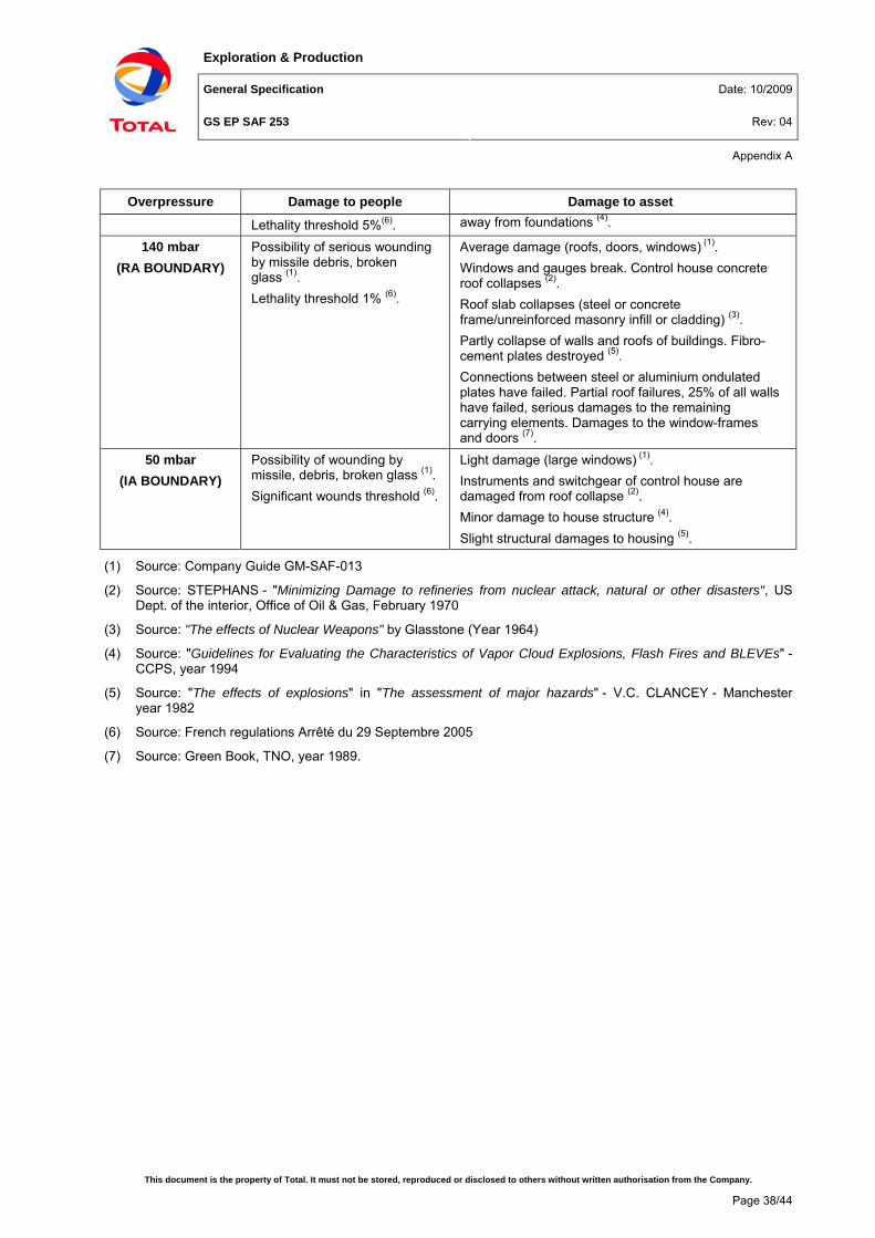
140 mbar (RA BOUNDARY)
Possibility of serious wounding by missile debris, broken glass (1). Lethality threshold 1% (6).
Average damage (roofs, doors, windows) (1). Windows and gauges break. Control house concrete roof collapses (2). Roof slab collapses (steel or concrete frame/unreinforced masonry infill or cladding) (3). Partly collapse of walls and roofs of buildings. Fibro-cement plates destroyed (5). Connections between steel or aluminium ondulated plates have failed. Partial roof failures, 25% of all walls have failed, serious damages to the remaining carrying elements. Damages to the window-frames and doors (7).
50 mbar (IA BOUNDARY)
Possibility of wounding by missile, debris, broken glass (1). Significant wounds threshold (6).
Light damage (large windows) (1). Instruments and switchgear of control house are damaged from roof collapse (2). Minor damage to house structure (4). Slight structural damages to housing (5).
(1) Source: Company Guide GM-SAF-013
(2) Source: STEPHANS - "Minimizing Damage to refineries from nuclear attack, natural or other disasters", US Dept. of the interior, Office of Oil & Gas, February 1970
(3) Source: "The effects of Nuclear Weapons" by Glasstone (Year 1964)
(4) Source: "Guidelines for Evaluating the Characteristics of Vapor Cloud Explosions, Flash Fires and BLEVEs" - CCPS, year 1994
(5) Source: "The effects of explosions" in "The assessment of major hazards" - V.C. CLANCEY - Manchester year 1982
(6) Source: French regulations Arrêté du 29 Septembre 2005
(7) Source: Green Book, TNO, year 1989.
Exploration & Production
General Specification Date: 10/2009
GS EP SAF 253 Rev: 04
Appendix A
This document is the property of Total. It must not be stored, reproduced or disclosed to others without written authorisation from the Company.
Page 39/44
Toxic threshold values
It shall be ensured that these data are up to date as they are regularly reviewed by regulatory agencies (e.g. NIOSH).
(9) Ineris - Fiche de données toxicologiques et environnementales des substances chimiques - Dioxyde de soufre SO2 - Version N°1 - Août 2005
Exploration & Production
General Specification Date: 10/2009
GS EP SAF 253 Rev: 04
Appendix A
This document is the property of Total. It must not be stored, reproduced or disclosed to others without written authorisation from the Company.
Page 40/44
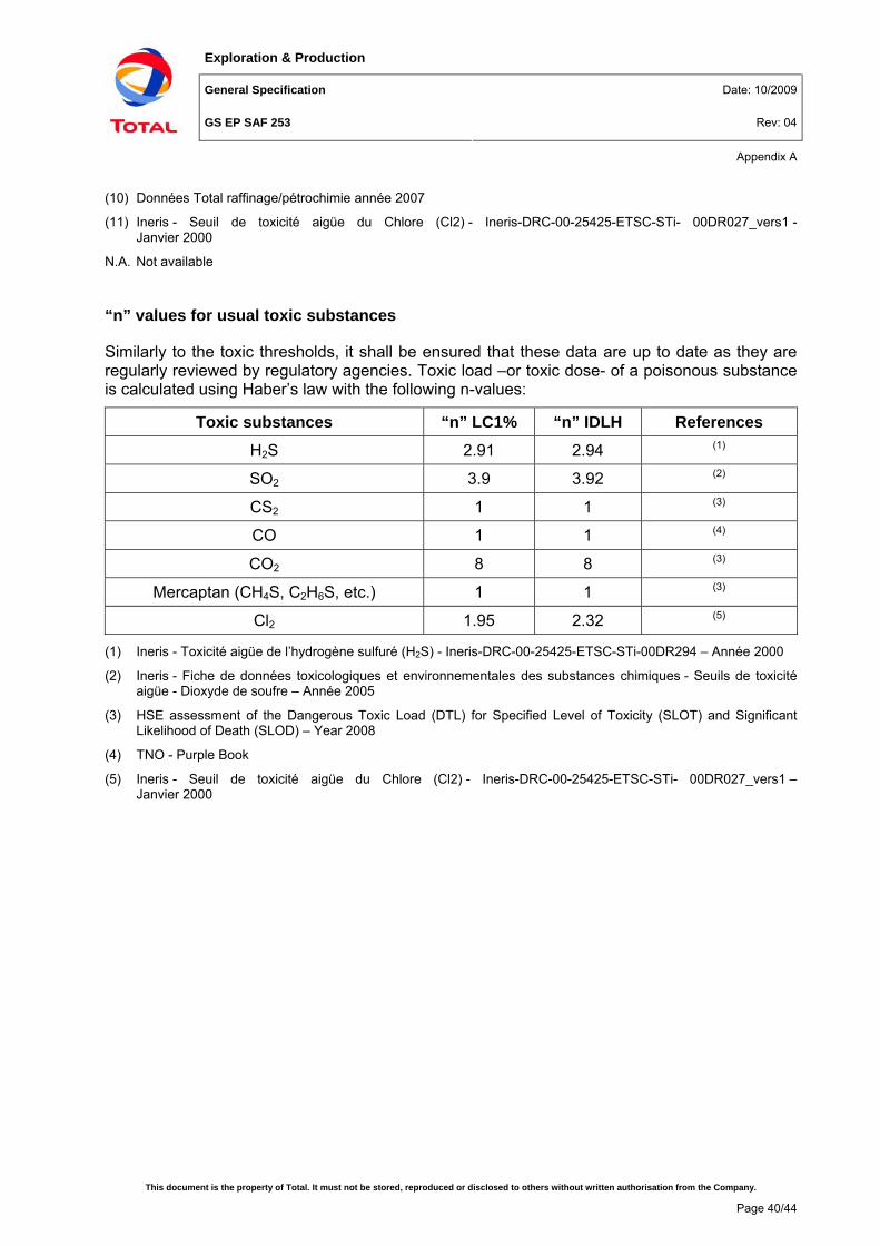
(10) Données Total raffinage/pétrochimie année 2007
(11) Ineris - Seuil de toxicité aigüe du Chlore (Cl2) - Ineris-DRC-00-25425-ETSC-STi- 00DR027_vers1 - Janvier 2000
N.A. Not available
“n” values for usual toxic substances
Similarly to the toxic thresholds, it shall be ensured that these data are up to date as they are regularly reviewed by regulatory agencies. Toxic load –or toxic dose- of a poisonous substance is calculated using Haber’s law with the following n-values:
(2) Ineris - Fiche de données toxicologiques et environnementales des substances chimiques - Seuils de toxicité aigüe - Dioxyde de soufre – Année 2005
(3) HSE assessment of the Dangerous Toxic Load (DTL) for Specified Level of Toxicity (SLOT) and Significant Likelihood of Death (SLOD) – Year 2008
(4) TNO - Purple Book
(5) Ineris - Seuil de toxicité aigüe du Chlore (Cl2) - Ineris-DRC-00-25425-ETSC-STi- 00DR027_vers1 – Janvier 2000
Exploration & Production
General Specification Date: 10/2009
GS EP SAF 253 Rev: 04
Appendix B
This document is the property of Total. It must not be stored, reproduced or disclosed to others without written authorisation from the Company.
Page 41/44
Appendix B Leak discharge rate calculation
If COMPANY discharge models do not take into account upstream isolation (i.e. operation of ESD after a given period of time), the leak discharge rate calculation shall be performed as per method described here-after.
The gas leak rate is expressed as: KP(t)(t)dtdm
=
with:
21
1γ1γ
od 1γ
2RTγMACK
⎥⎥⎥
⎦
⎤
⎢⎢⎢
⎣
⎡
⎟⎟⎠
⎞⎜⎜⎝
⎛+
=−+
where:
(t)dtdm is the leak rate (kg/s) at any given time t
P(t) pressure (Pa) at a given time t
Cd mean discharge coefficient for the leak hole (0.6 by default)
A area of the leak hole (m2) (assumed circular hole)
γ ratio of the specific heats for the gas
M molecular weight (kg)
R universal gas constant (8.314 J/mol K)
T0 gas temperature (K)
After integration, it comes:
• For t < isolation time: ⎟⎟⎠
⎞⎜⎜⎝
⎛−⎟
⎠⎞
⎜⎝⎛ −+=
MVKtRT
expKQP
KQP(t) o
o
• For t > isolation time: ⎟⎟⎠
⎞⎜⎜⎝
⎛ −−=
MV)tK(tRT
)expP(tP(t) ioi
where:
Q flow rate through the vessel (kg/s)
P0 gas pressure (Pa)
V vessel volume (m3)
t the time (s)
ti isolation time (s)
Remark: For "small" hole, i.e. when Q/K > P0, then P (t) = Cte = P0 until closure of ESDV and, as a consequence dm/dt = Cte = K x P0 with the assumption that the pressure prevailing in the pipe or vessel shall not increase beyond PSV set pressure and that said PSV set pressure is little different from P0.
An example of calculation follows.
Exploration & Production
General Specification Date: 10/2009
GS EP SAF 253 Rev: 04
Appendix B
This document is the property of Total. It must not be stored, reproduced or disclosed to others without written authorisation from the Company.
Computational results are then given in a table and a Figure.
t (s)
P0(t) (bara)
dm(t)/dt (kg/s)
t (s)
P0(t) (bara)
dm(t)/dt (kg/s)
0 76.3 124.3 601 38.0 61.9
50 66.7 108.6 650 28.4 47.1
100 59.4 96.8 700 21.9 35.6
150 53.9 87.8 750 16.6 27.0
200 49.8 81.0 800 12.5 20.4
250 46.6 75.9 850 9.5 15.4
300 44.3 72.0 900 7.2 11.7
350 42.4 69.1
400 41.1 66.9
450 40.1 65.2
500 39.3 63.9
550 38.7 63.0
600 38.2 62.3
Exploration & Production
General Specification Date: 10/2009
GS EP SAF 253 Rev: 04
Appendix B
This document is the property of Total. It must not be stored, reproduced or disclosed to others without written authorisation from the Company.
Page 43/44
0 100 200 300 400 500 600 700 800 900Time (sec.)
102030405060708090
100110120130140
Rel
ease
rate
(kg/
sec.
)
Exploration & Production
General Specification Date: 10/2009
GS EP SAF 253 Rev: 04
Appendix C
This document is the property of Total. It must not be stored, reproduced or disclosed to others without written authorisation from the Company.
Page 44/44
Appendix C Vapour Cloud Explosion (VCE) in units
Maximum explosion overpressure within module: 500 mbar for congested units.
Maximum explosion overpressure within module: 350 mbar for low congestion units.
Overpressure decay with distance shall be calculated with TNO's Multi-energy model curve No. 6 for congested units and average between curves No. 5 and 6 for low congestion unit. The explosive air/gas mixture (at stoichiometry) volume V taken into account for consequence calculation is the unit volume V for impacted and restricted areas and half unit volume for fire zones. This air/gas mixture volume V is assumed to be a hemisphere (radius R0) which is tangent to the unit edge as shown on the Figure below. TNO's Multi-energy model gives the radius to the overpressure criteria X (mbar) counted from the explosion centre: Rx mbar.
The distance of effect from the edge of the module, dx mbar, is given by the formula:
dx mbar = Rx mbar - R0
where Rx mbar is the gross result of the Multi-energy model.
350 or 500 mbar
X mbar
R xmbar
Module. Volume V
Hemisphere. Volume V or V/2
R0
d xmbar
Explosionover-pressure
ExplosionCenter
Equations used to model Rx mbar are as follows:
Explosion max. overpressure
350 mbar 500 mbar
R300 mbar 0.60515 x (35 V)1/3 1.03033 x (35 V)1/3
R200 mbar 0.99595 x (35 V)1/3 1.4654 x (35 V)1/3
R140 mbar 1.31117 x (35 V)1/3 1.93203 x (35 V)1/3
R50 mbar 3.4955 x (35 V)1/3 4.514 x (35 V)1/3
V: Air/gas mixture volume at stoichiometry in cubic metres