BP GROUP RECOMMENDED PRACTICES AND SPECIFICATIONS FOR ENGINEERING
Issue Date August 1997
Doc. No. GS 118-7 Latest Amendment Date
Document Title
THE FABRICATION, ASSEMBLY, ERECTIONAND INSPECTION OF AUSTENITIC AND
DUPLEX STAINLESS STEEL, CUPRO-NICKEL,
NICKEL BASE ALLOY, TITANIUM ANDZIRCONIUM PIPEWORK TO ASME B31.3
(Replaces BP Engineering Std 167 pt 3)
APPLICABILITY
Regional Applicability: International
SCOPE AND PURPOSE
This document is a supplement to ASME B31.3.
It provides additional detail to the base code and identifies BP's specific requirements forwelding procedure qualification, welder skill, workmanship and integrity of process pipework.
The primary objective of this Guidance for Specification is to allow application of ASMEB31.1 to BP plant pipework with confidence, fit-for-purpose and with enhanced safety.
AMENDMENTSAmd Date Page(s) Description___________________________________________________________________
CUSTODIAN (See Quarterly Status List for Contact)
Materials and InspectionIssued by:-
Engineering Practices Group, BP International Limited, Research & Engineering CentreChertsey Road, Sunbury-on-Thames, Middlesex, TW16 7LN, UNITED KINGDOM
FABRICATION REQUIREMENTS FOR 22%Cr AND 25%Cr DUPLEXSTAINLESS STEEL PIPEWORK.................................................................................32
FABRICATION REQUIREMENTS FOR TITANIUM AND ZIRCONIUM..................37
GS 118-7THE FABRICATION, ASSEMBLY, ERECTION AND
INSPECTION OF AUSTENITIC AND DUPLEXSTAINLESS STEEL ETC. PIPEWORK TO ANSI/ASME
B31.3
PAGE iii
FOREWORD
Introduction to BP Group Recommended Practices and Specifications for Engineering
The Introductory Volume contains a series of documents that provide an introduction to theBP Group Recommended Practices and Specifications for Engineering (RPSEs). In particular,the 'General Foreword' sets out the philosophy of the RPSEs. Other documents in theIntroductory Volume provide general guidance on using the RPSEs and backgroundinformation to Engineering Standards in BP. There are also recommendations for specificdefinitions and requirements.
Value of this Guidance for Specification
This Guidance for specification clarifies and amplifies a number of ASME clauses on the basisof BP's fabrication experience worldwide.
Application
This Guidance for Specification is intended to guide the owner in the use or creation of a fit-for-purpose specification for enquiry or purchasing activity.
It is a transparent supplement to ASME B31.3 1996 Edition, showing substitutions,qualifications and additions to the ASME text as necessary. As the titles and numbering of theBP text follow those of ASME , gaps in the numbering of the BP document may occur.Where clauses are added, the ASME text numbering has been extended accordingly.
Text in italics is Commentary. Commentary provides background information which supportsthe requirements of the Specification, and may discuss alternative options.
Throughout this document the term ‘owner’ is used to imply BP or their nominatedrepresentative. Any Specification subsequently prepared for the procurement of fabricatedpipework should define the particular party responsible for the stated actions.
This document may refer to certain local, national or international regulations but theresponsibility to ensure compliance with legislation and any other statutory requirements lieswith the user. The user should adapt or supplement this document to ensure compliance forthe specific application.
GS 118-7THE FABRICATION, ASSEMBLY, ERECTION AND
INSPECTION OF AUSTENITIC AND DUPLEXSTAINLESS STEEL ETC. PIPEWORK TO ANSI/ASME
B31.3
PAGE iv
Feedback and Further Information
Users are invited to feed back any comments and to detail experiences in the application of BPRPSE's, to assist in the process of their continuous improvement.
For feedback and further information, please contact Standards Group, BP International or theCustodian. See Quarterly Status List for contacts.
GS 118-7THE FABRICATION, ASSEMBLY, ERECTION AND
INSPECTION OF AUSTENITIC AND DUPLEXSTAINLESS STEEL ETC. PIPEWORK TO ANSI/ASME
B31.3
PAGE 1
1. INTRODUCTION
1.1 Scope
This document specifies general requirements supplementary to ASMEB31.3 - 1996 Edition, Chemical Plant and Petroleum Refinery Piping,Chapter V (Fabrication, Assembly and Erection) and Chapter VI(Inspection, Examination and Testing) and is applicable to both onshoreand offshore piping systems.
The welding of riser pipework and transmission pipelines is outside thescope of this Specification.
When additional text is to be read as an extension to the text of ASMEB31.3, the text numbering of ASME B31.3 has been extendedaccordingly.
The general requirements for the fabrication of the materials covered bythis Specification are detailed in the main body of the document, butspecific requirements for duplex stainless steels and titanium/zirconiumare detailed in Appendix C and D respectively.
2. QUALITY ASSURANCE
2.1 Initial Documentation
Before commencing fabrication of the pipework the fabricator shallprepare a quality plan and a set of design documents, both of whichshall be subject to approval by the owner.
These documents should normally include materials, welding andconsumable control procedures, welding and non-destructive testingprocedure specifications together with supporting qualification recordsand an illustration of their proposed areas of application. Mechanicalworking, heat treatment and leak testing procedures should also beincluded.
Previously qualified welding procedures may be considered for usewhere they comply with the requirements of the present document andare appropriate to the proposed scope of work. However, for criticalapplications, welding procedures shall require re-qualification, asdirected by the engineering design.
GS 118-7THE FABRICATION, ASSEMBLY, ERECTION AND
INSPECTION OF AUSTENITIC AND DUPLEXSTAINLESS STEEL ETC. PIPEWORK TO ANSI/ASME
B31.3
PAGE 2
Simplified welder instruction cards based on the qualified weldingprocedures should be prepared for each welding process/materialcombination and issued to each welder.
The quality plan shall include brief details and the sequence of allexaminations that will be performed by the fabricator. The names of theindividuals responsible for the implementation of all quality assuranceand quality control functions shall also be included.
It shall be the responsibility of the fabricator to inspect all materialsupon receipt and to ensure that the correct grade of material has beensupplied and that identification, dimensions, material quality and endpreparation are in accordance with the requisite standards andspecifications.
Different materials shall be kept in discrete sections of the storage areaand all material shall be marked in a manner that allows it to be relatedto the original manufacturers certification.
Procedures for the transfer of material identification marks shall beagreed with the owner prior to the commencement of fabrication.
Any material which is not readily identifiable shall be removed from theworksite and quarantined until its material grade and source can beconfirmed.
All materials shall be stored above ground and kept free from dirt,grease and other contaminants.
The fabricators procedures for the storage and control of weldingconsumables shall comply with the requirements of BP GS 118-4.
Positive identification and segregation of materials is an important issue andfabricators involved in the fabrication of alloy piping should submit a PositiveMaterial Identification (PMI) document setting out how they maintain and verify theidentity of materials during fabrication. API are currently drafting RP 578 whichsets out the requirements for a PMI system.
2.2 Production Documentation
At all stages of the work the fabricator shall maintain all relevantproduction records using a recording system approved by the owner.The records shall include:-
(i) Material and welding consumable certificates.
(ii) Post weld heat treatment records.
GS 118-7THE FABRICATION, ASSEMBLY, ERECTION AND
INSPECTION OF AUSTENITIC AND DUPLEXSTAINLESS STEEL ETC. PIPEWORK TO ANSI/ASME
B31.3
PAGE 3
(iii) Visual and dimensional inspection together with NDT andpressure test records.
(iv) Isometric drawings marked up with weld numbers.
(v) Welder and welding operator qualification test records.
(vi) Authenticated copies of NDT operators certificates.
(vii) Records of any agreed concessions to the fabrication standards.
On completion of the fabrication programme these records shall eitherbe passed to the owner or stored by the fabricator, as directed by theengineering design or the fabrication contract.
2.5 Pipework Marking
All pipework shall be identified by indelible marking, free from sulphur,chloride and other halogens. When spools will be subject to post-weldheat treatment a suitable titanium oxide pigmented heat resisting paintcontaining less than 250 ppm of lead, zinc, tin or copper shall be used.Vibro-etching techniques may be used for identification transfer butadhesive tapes or hard stamping, other that that with low stress stamps,shall not be used.
All applied marking shall have a life of at least one year in covered,unheated, storage.
The marking applied shall identify the material and the fabricator andinclude an item number enabling the spool to be traced to the relevantisometric drawing.
Guidance on suitable material identification colours may be obtained by referenceto BS 5383.
GS 118-7THE FABRICATION, ASSEMBLY, ERECTION AND
INSPECTION OF AUSTENITIC AND DUPLEXSTAINLESS STEEL ETC. PIPEWORK TO ANSI/ASME
B31.3
PAGE 4
3. SOUR AND CHLORIDE SERVICE.
Where external chloride attack of austenitic stainless steels isanticipated the requirements of Section 6 of BP GS 136-1 shall apply.
The following additional requirements should be considered for stainless steelpiping systems for service conditions which involve either sour environments orthose containing chlorides:-
a) Appendix B of BP GS 136-1 for austenitic stainless steels
b) NACE MR 0175, paragraph 3.9 for duplex stainless steels.
4. FABRICATION FACILITIES
The area used for fabrication shall be totally separate from that used for carbon andlow alloy steel. Further, each alloy type covered by this specification shall besegregated during fabrication. Adequate precautions shall be taken to prevent surfacecontamination by contact with jigs and fixtures manufactured in non-compatiblematerials. Separate sets of clearly identified cleaning and grinding equipment shall alsobe provided for each material.
The shop layout, equipment and production procedures shall be subject to the approvalof the owner, particularly where the fabrication of either titanium or zirconium isinvolved.
5. FABRICATION, ASSEMBLY AND ERECTION
Supplementary to Chapter V of ASME B31.3 - 1996 Edition.
The text of ASME B31.3 applies, except where amended by the following text or inthe engineering design.
328 WELDING
328.2 Welding Qualifications
328.2.1 Qualification Requirements
(a) Welding procedure specifications and procedure qualificationtest results shall be submitted to the owner for approval beforecommencement of fabrication.
Each procedure qualification record shall be certified by arecognised independent inspectorate.
GS 118-7THE FABRICATION, ASSEMBLY, ERECTION AND
INSPECTION OF AUSTENITIC AND DUPLEXSTAINLESS STEEL ETC. PIPEWORK TO ANSI/ASME
B31.3
PAGE 5
The SMAW, GTAW, PAW and SAW process are frequently employed forpipework fabrication and are considered to be acceptable weldingtechniques when used in accordance with this specification. The GMAWand FCAW processes are also often applied to piping fabrication.However, there are many variants of these two processes and in addition toensuring adequate procedure qualification it is important to ensure thatthe particular welding technique proposed for a given application is wellproven and will only be used by qualified and experienced welders.
(d) Unless otherwise specified by the engineering design, charpy Vnotch impact testing, as detailed in Appendix C, will be requiredon all duplex stainless steel piping materials, fittings andweldments for design temperatures below 0°C. The minimumdesign temperature for duplex stainless steels shall be -50°C.
In the case of austenitic stainless steels charpy V notch impacttesting will not generally be required for minimum designtemperatures greater than -196°C. However, if the possibilityof toughness degradation as a result of post weld heat treatmentexists (see 331.1.1) charpy V notch impact testing will berequired for austenitic stainless steels. The required impactenergy for austenitic stainless steels will be 40J at the minimumdesign temperature.
When impact testing is required the weld metal, fusion line andHAZ shall be tested. All charpy specimens shall be cuttransverse to the weld with the axis of the notch perpendicularto the surface of the test piece. Specimen and notch locationsshall be as shown in Figure 1. If only subsize charpy specimenscan be taken the standard energy reduction factors of 0.833 fora 10 x 7.5 mm specimen, and 0.667 for a 10 x 5 mm specimenshall be applied.
When a welding procedure requiring impact testing is to be usedin all positions, separate 2G and 5G qualifications shall beperformed.
(e) Backing rings are not permitted on pipework fabricated to thisSpecification.
(f) P-Numbers (also F-Numbers)
(i) The extension of a welding procedure qualification fromthe material on the procedure qualification record tomaterial of a different specification, even if it has thesame P-Number, shall be subject to approval by theowner.
GS 118-7THE FABRICATION, ASSEMBLY, ERECTION AND
INSPECTION OF AUSTENITIC AND DUPLEXSTAINLESS STEEL ETC. PIPEWORK TO ANSI/ASME
B31.3
PAGE 6
(ii) A new welding procedure qualification is required ifthere is a change of consumable classification orconsumable brand name, unless agreed otherwise by theowner.
(iii) A new welder performance test is required if there is achange of SMAW electrode brand name unless the brandcharacteristics do not differ sufficiently to affectperformance. Any such change shall be subject toapproval by the owner.
(g) The welding procedure specification shall require re-qualification if any of the following changes are made:-
(i) A change outwith the welding parameter toleranceranges specified in the qualified welding procedurespecification.
(ii) Any increase of more than 1 gauge number in theelectrode size from that used in the qualified weldingprocedure.
(iii) A change in the type of current, i.e. ac to dc or, in dcwelding, a change in electrode polarity, except wherethese changes are within the electrode manufacturer'srecommendations.
(h) Where any limitation on weldment hardness is specified in theengineering design, macrographic examination and hardnessmeasurements (HV 10) shall also form part of the weldingprocedure qualification.
Service conditions requiring restrictions to hardness levels are identifiedin BP GS 136-1.
(i) In addition to mechanical testing, welding procedure testsamples shall be subjected to dye penetrant and radiographicexamination. All non-destructive examination shall becompleted prior to the machining of test pieces.
(j) Ideally, welder performance tests for all positional weldingshould be carried out in both the 2G and 5G positions.However, subject to the agreement of the owner the welderperformance test may be undertaken in the 6G position. In thatcase, each welder shall also demonstrate his ability to deposit
GS 118-7THE FABRICATION, ASSEMBLY, ERECTION AND
INSPECTION OF AUSTENITIC AND DUPLEXSTAINLESS STEEL ETC. PIPEWORK TO ANSI/ASME
B31.3
PAGE 7
acceptable root runs in both the 2G and 5G positions. With theagreement of the owner this may be achieved by radiography ofthe welders first production welds in the 2G and 5G positions.
(k) Welders and welding operators shall be qualified by visualexamination and radiography except in the case of eithertitanium or zirconium where mechanical testing in accordancewith Appendix D shall also be required.
Subject to the provision of an authenticated CV and with the agreement ofthe owner, welders and welding operators may be qualified on their initialproduction welds for materials other than Titanium and Zirconium.
(l) Welder and welding operator qualification tests shall bewitnessed by the inspector.
The above additions and modifications to the qualification requirements have beenmade on the basis of fabrication experience and will allow welding to proceed withan improved level of confidence in both procedural qualification and welder skill.
Ultrasonics may be used in lieu of radiography when material thickness restricts thesuitability of radiography due to decreased sensitivity or extended exposure time.
328.2.4 Qualification Record. See 2.2.(v) of this document.
328.2.5 Test Joints
Welding procedure qualification tests should be carried out using pipematerials. All welder performance tests shall be undertaken on pipe.Performance testing shall utilise pipes of nominally the same chemicalanalysis as the production material, unless agreed otherwise by theowner. All test shall use filler metal of the same chemical compositionand manufacturer as those to be used in production.
A change in the type, or even the manufacturer, of filler metal can alter the fluidityof the weld pool and affect the ability of a welder to successfully complete a weldand this must be recognised in the extent of qualification testing required.
328.3 Welding Materials
328.3.1 Filler Metal
All GTAW filler wires shall be degreased prior to use and shallsubsequently be handled with clean gloves. The degreasant shall leaveno chloride or sulphide containing residues on the surface.
Filler metals will be selected with due regard to the need for the weld metal to, as aminimum, match the physical properties and corrosion resistance of the parentmaterial.
GS 118-7THE FABRICATION, ASSEMBLY, ERECTION AND
INSPECTION OF AUSTENITIC AND DUPLEXSTAINLESS STEEL ETC. PIPEWORK TO ANSI/ASME
B31.3
PAGE 8
In the case of the 300 series austenitic stainless steels the ferrite content of thedeposited weld metal should normally lie in the range 3-8%. However, undercertain service conditions it may be necessary to further limit the ferrite content. Incritical applications it may also be necessary to measure the ferrite content.
Stress relieving heat treatments in the range 900/950oC usually result in areduction of notch toughness in 300 series austenitic stainless steel weld metals.Where PWHT is specified for pipework in low temperature service or where thepiping design code includes notch toughness requirements, welding procedure testsshould ensure that the PWHT does not result in unacceptable embrittlement. This isespecially relevant for filler metals containing niobium or molybdenum.
Higher alloy austenitic stainless steels such as those containing ≥20% Ni and/or ≥4% Mo often require the use of nickel base weld metals in order to ensure soundweld metal of adequate corrosion resistance.
Some specific guidance on filler metal selection is provided in the appendices, butfinal guidance concerning any special requirements including the selection of fillermetal composition for dissimilar metal joints or the fabrication of corrosionresistant alloy clad components, should be provided by the engineering design.
328.3.2 Weld Backing Material
As stated in 328.2.1(e) backing rings shall not be used on pipeworkfabricated to this specification.
328.3.3 Consumable Inserts
Consumable inserts may only be used with the approval of the owner.
328.4 Preparation for Welding
328.4.1 Cleaning
Working practices shall be designed to minimise contamination and,before welding, internal and external surfaces shall be cleaned for adistance of at least 50 mm from the fusion face. The surfaces to bejoined by welding shall be stainless steel wire brushed and degreasedimmediately prior to welding. The degreasant shall leave no chloride orsulphide containing residues on the surface. On small pipes where it isnot possible to wire brush the internal surface an approved chemicalcleaning material shall be used.
GS 118-7THE FABRICATION, ASSEMBLY, ERECTION AND
INSPECTION OF AUSTENITIC AND DUPLEXSTAINLESS STEEL ETC. PIPEWORK TO ANSI/ASME
B31.3
PAGE 9
328.4.2 End Preparation
(a) General
(1) Materials, other than Zirconium and Titanium for whichthe requirements of Appendix D apply, shall be cut tosize and bevelled by plasma arc cutting, cold cutting,machining or an appropriate grinding technique.
Where plasma arc cutting is used, all surfaces adjacent tothe cut shall be cleaned prior to cutting by light grindingor wire brushing to bright metal. Immediately prior tocutting, the prepared surfaces are to be further cleanedby a suitable degreasant. Subsequent to plasma arccutting all surfaces shall be ground smooth and returnedto a bright metal finish.
(b) Circumferential Welds
(4) Weld metal buttering shall not be deposited to assistalignment or provide sufficient material for machiningwithout the approval of the owner.
(6) Prior to fit up the weld bevels shall be visually inspected,supplemented by dye penetrant or, if appropriate,magnetic particle examination where considerednecessary by either the fabricators or owners inspectionor welding personnel.
328.4.3 Alignment
(a) Circumferential Welds
Bore misalignment in circumferential butt joints shall not exceed1.5 mm without the approval of the owner.
(c) Branch Connection Welds
(3) Weld metal shall not be deposited to correct contour, shapeor tolerances without the permission of the owner.
(e) Fabrication Tolerances
Fabrication tolerances shall comply with Figure 2 unlessotherwise approved by the owner. Category M tolerances shall
GS 118-7THE FABRICATION, ASSEMBLY, ERECTION AND
INSPECTION OF AUSTENITIC AND DUPLEXSTAINLESS STEEL ETC. PIPEWORK TO ANSI/ASME
B31.3
PAGE 10
be used for service temperatures above 460°C and class ratings900 and above or when specified within the engineering design.
Weldments in austenitic steels are prone to distortion due to their highcoefficients of thermal expansion and low thermal conductivity.Fabricators should consider this before commencing welding. In somecases, changes to design details will mitigate the risk of distortion and thefabricator shall consult with the owner if, in his opinion, such designchanges are necessary to comply with defined tolerances.
328.5 Welding Requirements
328.5.1 General
(b) All welds shall be marked with the welders/welding operatorsidentification symbol.
(c) Preference shall be given to the use of line up clamps, or bridgetacks which do not interfere with the deposition of a continuousroot run. Root tack welding, when approved, shall notcommence until bore purging has been established. When thetacks are to be incorporated in the final weld, they must beproperly cleaned prior to the root pass and the ends feathered bygrinding. In addition the delay between tack welding and thedeposition of the root pass shall be minimised to reducecontamination. The removal of bridge tacks shall be bymechanical grinding only.
In order to reduce the risk of contamination of the weld zone clamp faceand bridge tack materials should be of the same material as, or compatiblewith, that being welded.
(d) Peening shall not be permitted on any pass.
(f) Unless otherwise stated in the manufacturers installationinstructions, all welds for the installation of in-line valves shallbe performed with the valve in the fully opened position.
(g) GTAW or PAW shall be used for the root pass of all materialscovered by this standard. GTAW or PAW are also thepreferred techniques for the second (hot) pass. However, whereappropriate, SMAW may be used for the hot pass provided theelectrode size does not exceed 2.5 mm. SMAW shall not beused on piping less than NPS 2½ except where the welders havedemonstrated their ability to use SMAW on pipe of thesediameters.
GS 118-7THE FABRICATION, ASSEMBLY, ERECTION AND
INSPECTION OF AUSTENITIC AND DUPLEXSTAINLESS STEEL ETC. PIPEWORK TO ANSI/ASME
B31.3
PAGE 11
(h) Butt welds and pressure containment fillet welds in NPS 1½ andsmaller pipes shall use GTAW or PAW for all passes.
(i) All GTAW and PAW equipment shall use either a highfrequency starting unit or an alternative programmed touchstarting unit. A current decay device should also be fittedtogether with a gas lens to improve gas shielding of the weldpool.
(j) GTAW and PAW shall only be used under enclosed shopconditions unless adequate weather protection is provided ateach outdoor location where these techniques are to be used.
Where gas shielded processes are being used moderate air currents canresult in the loss of the shielding gas leading to weld defects. Thus,sufficient screening must be used under such circumstances to keep windsand draughts away from the welding area.
(k) The composition of shielding gas used for welding shall becompatible with the alloy being welded and the weld propertiesrequired.
(l) The bore of all materials covered by this Specification shall beadequately purged during the deposition of the weld to ensurethat no oxidation or coking of the root run and internal surfaceoccurs.
In general high purity argon or argon based gas mixtures should be used for borepurging. However, in the case of austenitic stainless steels, nitrogen or nitrogenbased gas mixtures may be considered for use. Argon based gas mixtures containinga percentage of nitrogen may be beneficial for use with duplex stainless steels(Appendix C)
When erecting pipe spools, particularly in large diameter pipework, adequateforethought should be given to the installation of internal dams to minimise theusage of purge gas.
When initiating the flow of purge gas a general rule of thumb that may be used isthat 'all air may be removed by the admission of a volume of purge gas at least sixtimes the volume of air being displaced.' However, when welding more reactivematerials, such as titanium and zirconium, dew point measurements are desirable toestablish the quality of the purge and, in general, oxygen meters are valuable formonitoring purposes.
It is often adequate for austenitic steels to ensure a flow of purge gas during thedeposition of the root and second pass provided that the bore is subsequently sealedto prevent atmospheric ingress. However, in the case of the more reactive materialssuch as titanium and zirconium a positive purge flow should by maintainedthroughout the welding operation.
GS 118-7THE FABRICATION, ASSEMBLY, ERECTION AND
INSPECTION OF AUSTENITIC AND DUPLEXSTAINLESS STEEL ETC. PIPEWORK TO ANSI/ASME
B31.3
PAGE 12
Guidance on the need for extended purge times is provided in the appendices andwill be supplemented as necessary by the engineering design.
(m) SAW and, where approved, FCAW and GMAW, shall not beused for pipes smaller than NPS 6 unless otherwise agreed bythe owner.
(n) All root welds should be completed without interruption otherthan to allow the welder to take a new length of filler wire or toreposition himself.
(o) Vertical down welding is not permitted.
(p) Temporary attachments to the outside surface of high alloypiping materials shall be minimised and shall not be madewithout the approval of the owner. Attachments which arepermitted shall be made in a controlled manner to avoidoxidation of the internal surface of the pipework. The fabricatorshall advise what precautions he proposes to take with regard tofixing and removing temporary attachments to and from suchmaterials.
(q) Whenever practicable, fillet welded joints used for pressurecontainment should have a minimum of three weld passes, twoof which should be showing for visual inspection.
The above additions and modifications to the welding requirements have been madeon the basis of fabrication experience and will allow welding to proceed with animproved level of confidence in workmanship and practice.
328.5.3 Seal Welds
Joints to be seal welded shall be made up clean and without the use oftape or any compound. Welding shall be performed in accordance witha qualified procedure by a qualified welder. The welding shall notcause damage to the threaded fitting and all exposed threads shall becovered by the seal weld.
Threaded joints should be assembled in such a manner that a maximum of threethreads are exposed prior to welding.
328.5.4 Welded Branch Connections
When designing angled branch connections, in addition to consideringthe stress concentration effects care must be taken to ensure sufficientaccess for welding in the acute angle section.
GS 118-7THE FABRICATION, ASSEMBLY, ERECTION AND
INSPECTION OF AUSTENITIC AND DUPLEXSTAINLESS STEEL ETC. PIPEWORK TO ANSI/ASME
B31.3
PAGE 13
When set-on integrally reinforced branch connections are used, it should be notedthat the wall thickness of the connection may well be in excess of that necessary toprovide the required level of reinforcement. Consequently, no reinforcementcontribution is necessary from the weld metal and the deposition of a branch weldwith an excessive throat thickness may lead to unacceptable distortion of the mainrun pipe. The engineering design should provide guidance on the sizing of branchwelds when using this type of fitting. Controlled weld profiles are required whenthe branch is on severe cyclic duty.
If set in integrally reinforced branch connections are used particular care should betaken in fit-up, jigging and in developing an overall welding sequence to minimisethe extent of any 'sinking'.
The use of integrally reinforced branch connections on thin wall pipes, typicallyschedule 10 and below, should be avoided.
328.5.5 Fabricated Laps
Fabricated laps shall not be used without the agreement of the owner.
328.5.6 Welding for Severe Cyclic Conditions
The weld reinforcement shall be smooth and regular. It shall blendsmoothly with the external surface of the pipe to minimise possiblestress concentration effects.
The engineering design should provide any specific guidance considered necessaryfor weld profiles in severe cyclic duty.
328.5.7 Proximity of Welds
(i) The toes of adjacent circumferential butt welds shall be nocloser than four times the nominal thickness of the pipe with, inthe case of NPS 12 and below, a minimum acceptable separationof 50 mm. For pipe sizes greater than NPS 12 the minimumacceptable separation shall be 100 mm.
(ii) Branch and non pressure part attachment welds shall not crosslongitudinal seams or circumferential butt welds and shall besubject to the toe to toe separation distance specified forcircumferential butt welds.
Where such intersections are unavoidable the main weld shall besubject to non-destructive examination prior to making theattachment weld.
(iii) Joints involving the intersection of more than two welds shall beavoided.
GS 118-7THE FABRICATION, ASSEMBLY, ERECTION AND
INSPECTION OF AUSTENITIC AND DUPLEXSTAINLESS STEEL ETC. PIPEWORK TO ANSI/ASME
B31.3
PAGE 14
330 PRE-HEATING
330.1 General
The materials covered by this standard do not in general require preheating forwelding except to drive off moisture or raise component temperature above 0°C.
330.1.1 Requirements and Recommendations
Cupro-nickel alloys may be preheated to a maximum temperature of50°C.
Oxy-fuel gas welding or cutting torches may only be used for pre-heating when fitted with proprietary preheating nozzles.
Preheating of cupro-nickel is not normally necessary. However, for high heat sinkwelds, i.e. tee butt welds, or where one of the members being fabricated is relativelythick, preheats of up to 50oC may be applied to aid fusion.
330.1.3 Temperature Verification
(b) Thermocouples, to measure pre-heat temperature, shall not bedirectly attached to pressure parts without the agreement of theowner.
330.1.4 Pre-heat Zone
The pre-heat zone shall extend 75 mm or a distance equal to four timesthe material thickness, which ever is the greater, beyond each edge ofthe weld.
330.1.5 Interpass Temperature
The maximum interpass temperature shall not exceed the stated limitsfor the following materials:
Cupro-nickel, }}
high alloy austenitic stainless steels } 100°Ccontaining ≥20% Ni and/or ≥4% Mo, }
}Nickel based alloys containing >10% Mo, }
Nickel based alloys containing <10% Μo, 150°C
GS 118-7THE FABRICATION, ASSEMBLY, ERECTION AND
INSPECTION OF AUSTENITIC AND DUPLEXSTAINLESS STEEL ETC. PIPEWORK TO ANSI/ASME
B31.3
PAGE 15
300 series austenitic stainless steels. 200°C
Guidance concerning interpass temperatures for duplex stainless steelsand titanium/zirconium is given in Appendices C and D.
When the 300 series austenitic stainless steels are utilised in critical applications,the interpass temperature may be restricted to 150oC by the engineering design.Particular requirements for special or proprietary alloys shall also be detailed inthe engineering design.
331 HEAT TREATMENT
331.1 General
331.1.1 Heat Treatment Requirements
(e) Heat treatment is not normally considered necessary forthematerials covered by this Specification. However, in the caseof austenitic stainless steels it may be necessary to provide somereduction in the residual stress level after welding or coldbending. The engineering design shall identify any specificapplications for which heat treatment is required.
When austenitic stainless steels are exposed to environments containingchlorides or polythionic acids the presence of residual stresses generatedby either welding or mechanical working may lead to stress corrosioncracking. Stress relief heat treatment may consequently be necessary priorto service
(f) Where a stress relief heat treatment of austenitic steels isspecified by the engineering design the welds shall be heated toa temperature in the range 900-950°C and held for a period ofone hour per 25 mm of thickness. The minimum soaking periodshall be one hour.
(g) Low melting point metals such as aluminium, lead, tin, copper,zinc, cadmium and mercury, and their alloys, shall not bepermitted to contact any surfaces which will undergo hotforming, welding or post-weld heat treatment.
Possible sources of such contamination include solder, galvanisedcomponents, and certain types of paint.
GS 118-7THE FABRICATION, ASSEMBLY, ERECTION AND
INSPECTION OF AUSTENITIC AND DUPLEXSTAINLESS STEEL ETC. PIPEWORK TO ANSI/ASME
B31.3
PAGE 16
331.1.4 Heating and Cooling
(i) When a furnace heat treatment is applied to austenitic stainlesssteels, the furnace temperature shall not exceed 300°C when thepipework is loaded.
(ii) For austenitic stainless steels the maximum heating rate above300°C shall not exceed 200°C per hour.
(iii) Following elevated temperature soaking austenitic pipeworkshall be removed from the furnace and rapidly cooled in air.
Should heat treatment be necessary during the fabrication of any otheralloy covered by this Specification, full details of the soaking temperatureand time along with of the applicable heating and cooling rates will beprovided by the engineering design.
331.1.6 Temperature Verification
Where practical, thermocouples shall be attached to spoolpieces at aminimum of six equally spaced locations, adjacent to welds, prior toheat treatment.
Procedures for the attachment of thermocouples by capacitor dischargewelding shall be approved by the owner and the use of this techniquecarefully monitored.
331.1.7 Hardness Tests
The requirement for and extent of any hardness testing shall bespecified by the engineering design.
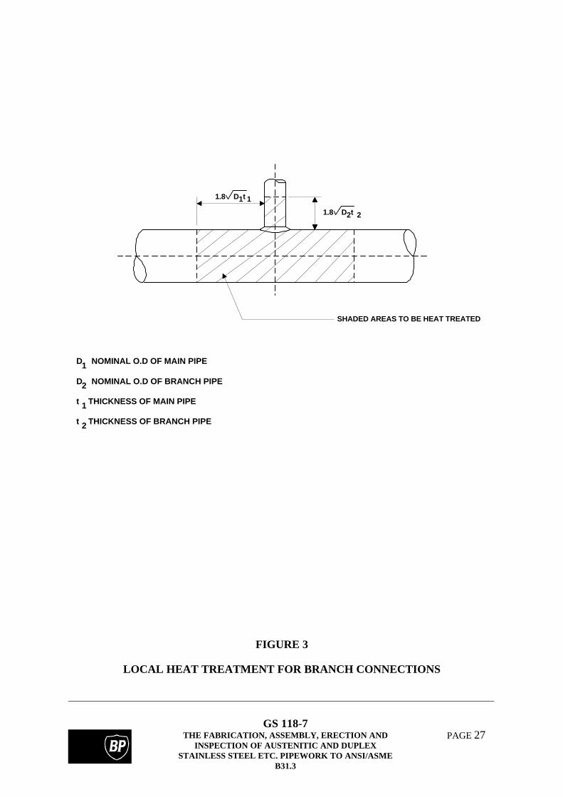
331.2.6 Local Heat Treatment
When a local heat treatment is applied, the weld shall be sufficientlyheated and insulated to ensure that (for a pipe, of NPS 'D' and wallthickness 't'), the specified heat treatment temperature is achieved at the
weld and that at a distance of 1.8 Dt on both sides of the weld, atemperature of not less than half of the specified heat treatmenttemperature is attained.
In the case of branch attachments, the temperature gradient shall besuch that the length of material from each crotch heated to a
temperature equalling half the heat treatment temperature shall be 1.8 Dtwhere 'D' and 't' are the nominal diameter and thickness of the main pipeand branch as appropriate (Figure 3).
GS 118-7THE FABRICATION, ASSEMBLY, ERECTION AND
INSPECTION OF AUSTENITIC AND DUPLEXSTAINLESS STEEL ETC. PIPEWORK TO ANSI/ASME
B31.3
PAGE 17
332 BENDING AND FORMING
The bend manufacturers procedures must be reviewed to confirm that adequatecontrol is being exercised in the heating, cooling and inspection of the bends.
Typical tolerances on completed bends should be:-
- ovality at any cross section of bend should not exceed 5%- wall thickness after bending should not be less than nominal design thickness- angle of bend should be within 0.5o of nominal
332.1 General
All bending of stainless steels and nickel alloy pipe should be done cold.However, where the size and schedule of the pipe is such that coldbending becomes impracticable hot bending may be utilised. Unlessstated otherwise in the engineering design, factory manufactured pipingfittings shall be solution heat treated in the temperature range specifiedby the alloy manufacturer.
For some highly corrosive applications the use of pulled bends is not permitted.For such applications, the engineering design will define the appropriate bendmanufacturing processes.
332.2 Bending
332.2.2 Bending Temperature
(a) Cold bending of austenitic stainless steel shall be performed attemperatures below 425°C. Cold bending of duplex stainlesssteels shall be performed at temperatures below 300°C. Coldbends in austenitic or duplex stainless steels shall be heat treatedonly in applications where there is a likelihood of stresscorrosion cracking due to chlorides or polythionic acid inservice.
Any heat treatment of duplex stainless steels must produce a microstructureappropriate to the intended service conditions. It is recommended that heattreatment procedure qualification is carried out to demonstrate the adequacy of anyheat treatment that is to be applied to duplex stainless steels.
Where cold bending of alloy pipe produces local strain in excess of 10%consideration should be given to the application of a post forming heat treatmentand any specific requirements should be stated in the engineering design.
GS 118-7THE FABRICATION, ASSEMBLY, ERECTION AND
INSPECTION OF AUSTENITIC AND DUPLEXSTAINLESS STEEL ETC. PIPEWORK TO ANSI/ASME
B31.3
PAGE 18
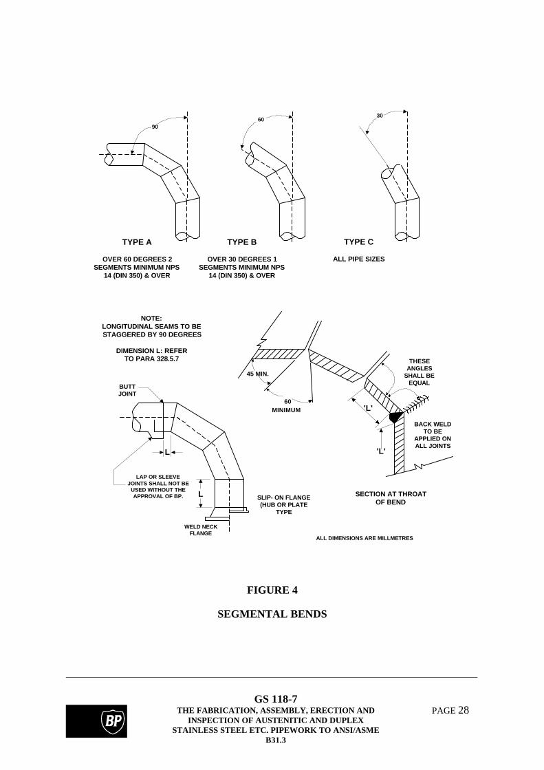
322.2.3 Corrugated and Other Bends
Fabricated mitre (segmented) bends are not generally permitted.However, subject to the agreement of the owner, limited use of mitredbends in accordance with Figure 4 may be proposed for applicationspermitted by BP RP 42-1.
The 'cut and shut' design shall not be used.
Any further guidance or restrictions that may be necessary for bending and formingthe materials covered by this Specification will be detailed by the engineeringdesign.
335 ASSEMBLY AND ERECTION
335.1 General
335.1.1 Alignment
(a) Piping distortions. The application of heat for the correction ofany minor distortions in pipe spools manufactured in the alloyscovered by this Specification shall be approved by the owner.
335.1.2 Bolting Procedures
Bolting procedures should be provided for each joint or group of jointsto be assembled. These procedures shall contain the followinginformation:-
(i) Required bolt load or stress.
(ii) Tightening method.
(iii) Tightening sequence.
(iv) Elongation measurement requirements, where consideredappropriate.
6. INSPECTION, EXAMINATION, AND TESTING
Supplementary to Chapter VI of ASME B31.3 - 1996 Edition.
The text of ASME B31.3 applies except where amended by additional requirementsspecified in the following text or in the engineering design.
GS 118-7THE FABRICATION, ASSEMBLY, ERECTION AND
INSPECTION OF AUSTENITIC AND DUPLEXSTAINLESS STEEL ETC. PIPEWORK TO ANSI/ASME
B31.3
PAGE 19
340 INSPECTION
340.4 Qualifications of the Owners Inspector
BP will appoint a competent and experienced person having relevantpractical and theoretical knowledge as the Owners Inspector.
341 EXAMINATION
341.3 Examination Requirements
341.3.1 General
(a) For all materials, final examination shall be performed aftercompletion of any heat treatment.
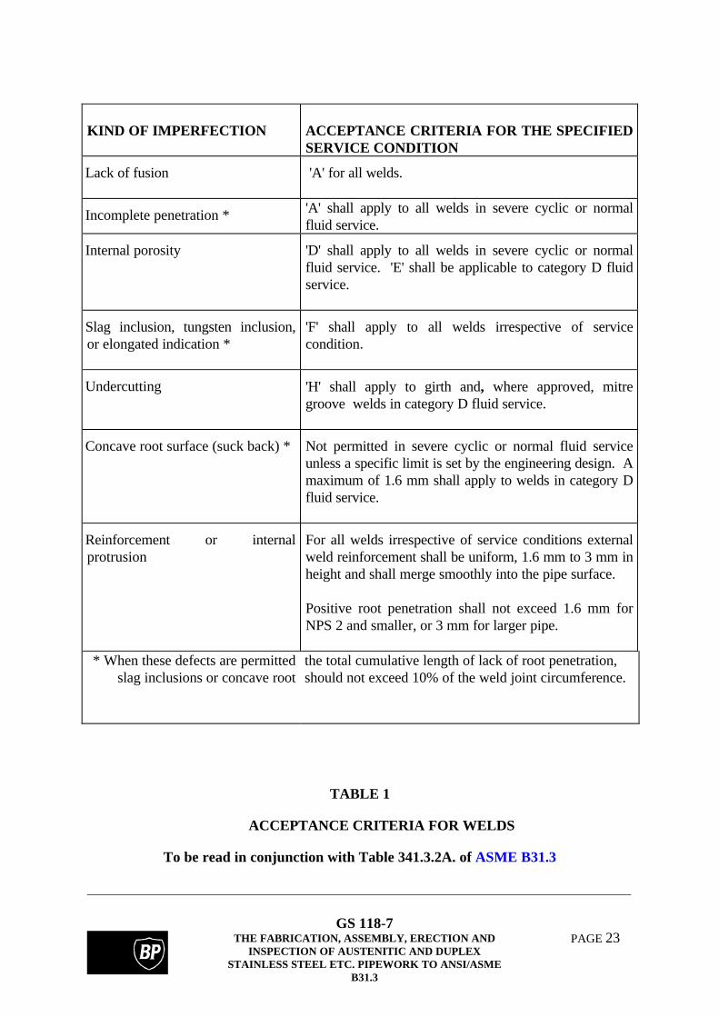
341.3.2. Acceptance Criteria
(a) Table 341.3.2A as amplified by Table 1 of this document statesacceptance criteria for welds.
341.4 Extent of Required Examination
The extent of the required examination shall, for all fluid categories,depend on the criticality rating of an individual piping system. Themethod of determining criticality rating shall be specified by theengineering design and assigned values shall be recorded in the pipingline lists
342 EXAMINATION PERSONNEL
342.1 Personnel Qualification and Certification
Only personnel certified in accordance with PCN, CSWIP or ASNTrecommended practice SNT-TC-1A, shall be allowed to undertake theexaminations. In the case of ASNT, assessment of operatorcompetence should have been undertaken by an external authority.Other equivalent qualifications may be accepted at the discretion of theowner. All personnel qualifications shall be subject to approval by theowner.
GS 118-7THE FABRICATION, ASSEMBLY, ERECTION AND
INSPECTION OF AUSTENITIC AND DUPLEXSTAINLESS STEEL ETC. PIPEWORK TO ANSI/ASME
B31.3
PAGE 20
343 EXAMINATION PROCEDURES
Only examination procedures approved as required by paragraph 2.1 ofthis document shall be used.
344 TYPES OF EXAMINATION
344.2 Visual Examination
344.2.1 Definition
Visual examination shall include an examination of the internal surfaceof the weld where possible; full use being made of suitable opticalinstruments.
344.5 Radiographic Examination
344.5.1 Method
(a) X-ray techniques are preferred for all shop radiography ofpipework up to 25 mm wall thickness. However, where the useof X-rays is impractical, gamma ray isotopes may be usedsubject to the approval of the owner.
In each case the technique shall be qualified using a source sideimage quality indicator of the wire type to BS 3971 or DIN 54109 Part 1. The single wall, single image technique should beused when ever possible. Lead intensifying screens and finegrain high contrast film shall be used. Film density shall be 2.0 -3.0 through the thickest portion of the weld and theradiographic sensitivity shall be as shown in Table 2 of thisdocument.
(b) Radiography of production welds shall use a wire type IQI witheach film exposure and this shall be placed on the source sidewhere accessible. When the complete joint circumference isradiographed in a single exposure four IQIs placed at 90 degreeintervals shall be used.
(c) Where set-on branch connections are permitted by theengineering design, they should be subject to intermediateradiography with the film on the bore side of the joint when theweld depth is similar to the wall thickness and before thereinforcing fillet is applied.
GS 118-7THE FABRICATION, ASSEMBLY, ERECTION AND
INSPECTION OF AUSTENITIC AND DUPLEXSTAINLESS STEEL ETC. PIPEWORK TO ANSI/ASME
B31.3
PAGE 21
344.5.3 Extent of Radiography
(c) Spot Radiography. Spot radiography shall not be used forcircumferential, mitre or branch welds.
344.6 Ultrasonic Examination for Metals
Where ultrasonic examination is required the approval of BP shall beobtained for the procedures for each joint configuration and thickness.It will normally be restricted to wall thickness greater than 10 mm.
When fabricating pipework having a wall thickness in excess of 25 mm,consideration should be given to the examination of the root region when welding ispartially complete to a depth of approximately 30% of the wall thickness. This willminimise the need for through wall repairs.
Following any necessary repairs to the root and re-examination, the weld should becompleted and subjected to final examination.
345 TESTING
345.4 Hydrostatic Leak Testing
The fabricators hydrostatic test procedure, giving details of test fluid,minimum temperature, test pressure, pressure recording and controlmethod and holding time, shall be reviewed by the owner.
Subsequent to hydrostatic testing, pipe spools that are to be storedprior to installation shall be thoroughly dried have their ends sealed toprevent ingress of dirt, moisture or other contaminants. Flange facesshall be coated with a suitable corrosion preventative.
Hydrotesting should be carried out after the completion of any specified heattreatment.
Current practice is to perform the hydrostatic after the piping has been painted.Where the owner requires hydrotest prior to any painting or, alternatively, only thewelds left unpainted until after the hydrotest this requirement should be clearlystated in the engineering design documentation.
Where piping spools are to stored prior to installation, due consideration should begiven to the need for the introduction of a suitable vapour phase inhibitor/biocide.
345.4.1 Test Fluid
On all austenitic and duplex stainless steels piping fabricated to thisspecification, potable water having a chloride content of less than 30ppm should be used for hydrostatic testing. Water having a chloridecontent above 100 ppm shall not be used and where it is necessary to
GS 118-7THE FABRICATION, ASSEMBLY, ERECTION AND
INSPECTION OF AUSTENITIC AND DUPLEXSTAINLESS STEEL ETC. PIPEWORK TO ANSI/ASME
B31.3
PAGE 22
use water within a range of 30 to 100 ppm, lines shall be flushed withwater having a chloride content of less than 30 ppm within a shortperiod of testing.
Zirconium, titanium, copper and nickel based alloy pipework may behydrotested using clean, potable water.
347 Weld Repairs
Prior to the commencement of fabrication the fabricator and the ownershall agree which types of welding defects are to be regarded asnotifiable prior to rectification.
The fabricator shall subsequently advise the owner of the need to carryout any such repair and obtain approval prior to commencing anyfurther work on defective welds.
Detailed records of all repairs shall be retained by the fabricator.
Repair welding shall in accordance with approved repair proceduresunless the use of the original procedure has been agreed with theowner.
As a minimum, all repair welds shall be inspected to their full extentusing the techniques used for the inspection of the initial weld. Theowner may require that additional inspection be applied to repairs incertain circumstances.
All weld repairs shall, where practical, be carried out prior to anyspecified post weld heat treatment. Where a second heat treatment isnecessary the details of the procedure qualification requirements shallbe agreed with the owner.
Application of a second heat treatment may have adverse effects on the propertiesof weld metal and some base materials. Thus it may be necessary to consider aqualification test using previously welded and heat treated material forqualification of the repair techniques. In such cases additional testing of the parentmaterial should be carried out.
GS 118-7THE FABRICATION, ASSEMBLY, ERECTION AND
INSPECTION OF AUSTENITIC AND DUPLEXSTAINLESS STEEL ETC. PIPEWORK TO ANSI/ASME
B31.3
PAGE 23
KIND OF IMPERFECTION ACCEPTANCE CRITERIA FOR THE SPECIFIEDSERVICE CONDITION
Lack of fusion 'A' for all welds.
Incomplete penetration * 'A' shall apply to all welds in severe cyclic or normalfluid service.
Internal porosity 'D' shall apply to all welds in severe cyclic or normalfluid service. 'E' shall be applicable to category D fluidservice.
'F' shall apply to all welds irrespective of servicecondition.
Undercutting 'H' shall apply to girth and, where approved, mitregroove welds in category D fluid service.
Concave root surface (suck back) * Not permitted in severe cyclic or normal fluid serviceunless a specific limit is set by the engineering design. Amaximum of 1.6 mm shall apply to welds in category Dfluid service.
Reinforcement or internalprotrusion
For all welds irrespective of service conditions externalweld reinforcement shall be uniform, 1.6 mm to 3 mm inheight and shall merge smoothly into the pipe surface.
Positive root penetration shall not exceed 1.6 mm forNPS 2 and smaller, or 3 mm for larger pipe.
* When these defects are permittedslag inclusions or concave root
the total cumulative length of lack of root penetration,should not exceed 10% of the weld joint circumference.
TABLE 1
ACCEPTANCE CRITERIA FOR WELDS
To be read in conjunction with Table 341.3.2A. of ASME B31.3
GS 118-7THE FABRICATION, ASSEMBLY, ERECTION AND
INSPECTION OF AUSTENITIC AND DUPLEXSTAINLESS STEEL ETC. PIPEWORK TO ANSI/ASME
B31.3
PAGE 24
Maximum ThicknessX-Radiography Gamma-Radiography
millimetres inches
3 1/8 2.4% +
6 ¼ 1.6% 2.4% *
12 1/2 1.4% 2.4%
25 1 1.2% 1.7%
40 11/2 1.1% 1.5%
* Based on double wall/single image radiography.
+ To be agreed with the owner following the production of a test radiography.
TABLE 2
ACCEPTABLE RADIOGRAPHIC SENSITIVITY LEVELS
Using a wire type IQI to BS 3971 or DIN 54 109
GS 118-7THE FABRICATION, ASSEMBLY, ERECTION AND
INSPECTION OF AUSTENITIC AND DUPLEXSTAINLESS STEEL ETC. PIPEWORK TO ANSI/ASME
B31.3
PAGE 25
WELD CENTRELINE NOTCHES
2mm MAX
2mm MAX
FL
FL + 1mmFL + 2mm
FL + 5mm
FUSION LINE (FL) AND HAZNOTCH POSITIONS
WELD METAL CENTRE LINE, FL AND FL+2mm TESTING IS MANDATORY. THE NEED FOROTHER NOTCH LOCATIONS TO BE TESTED SHALL BE IDENTIFIED BY THEENGINEERING DESIGN.
<25mm WALL THICKNESS : CHARPY SPECIMENS TO BE TAKEN FROM WELD CAP>25mm WALL THICKNESS : CHARPY SPECIMENS TO BE TAKEN FROM THE ROOT AND CAP REGIONS
FIGURE 1
CHARPY NOTCH LOCATIONS
GS 118-7THE FABRICATION, ASSEMBLY, ERECTION AND
INSPECTION OF AUSTENITIC AND DUPLEXSTAINLESS STEEL ETC. PIPEWORK TO ANSI/ASME
B31.3
PAGE 26
CL
CL
CL
CL
A
A
A
A
A
E
D
C/L FLANGE OR BRANCH
C
B
A
ITEMCAT. D OR
NORMAL SERVICECONDITIONS
CAT. M. OR SERVERE CYCLIC
TEMP > 460ºCLASS RATING > 900
A + 3mm MAX. FROM INDICATEDCENTRE TO FACE, LOCATION OF
DIMENSION FROM FACE TO FACE.ATTACHMENTS ETC.
B 8% MAX ( FOR INT. PRESS) 2% MAX3% MAX (FOR EXT PRESS)
FLATTENING MEASURED ASAND MIN O.D AT ANY CROSS
DIFFERENCE BETWEEN THE MAXSECTION
C + 3mm MAX LATERAL TRANSLATIONOF BRANCHES OR CONNECTIONS
+ 1.5 mm MAX. LATERALTRANSLATION OF BRANCHES OR
CONNECTIONSD + 1.5mm MAX ROTATION OF FLANGES
MEASURED AS SHOWNFROM THE INDICATED POSITION ,
E 0.75mm MAX OUT OF ALIGNMENT OFFLANGES FROM THE INDICATED
POSITION. MEASURED ACROSS ANYDIAMETER
0.4mm MAX OUT OF ALIGNMENTOF FLANGES FROM THE
INDICATED POSITION, MEASUREDACROSS ANY DIAMETER
FIGURE 2
DIMENSIONAL TOLERANCES FOR FABRICATED PIPEWORK
GS 118-7THE FABRICATION, ASSEMBLY, ERECTION AND
INSPECTION OF AUSTENITIC AND DUPLEXSTAINLESS STEEL ETC. PIPEWORK TO ANSI/ASME
B31.3
PAGE 27
1 11.8 D t
1.8 D t2 2
SHADED AREAS TO BE HEAT TREATED
D NOMINAL O.D OF MAIN PIPE
D NOMINAL O.D OF BRANCH PIPE
t THICKNESS OF MAIN PIPE
t THICKNESS OF BRANCH PIPE
1
2
1
2
FIGURE 3
LOCAL HEAT TREATMENT FOR BRANCH CONNECTIONS
GS 118-7THE FABRICATION, ASSEMBLY, ERECTION AND
INSPECTION OF AUSTENITIC AND DUPLEXSTAINLESS STEEL ETC. PIPEWORK TO ANSI/ASME
B31.3
PAGE 28
90
TYPE A
OVER 60 DEGREES 2SEGMENTS MINIMUM NPS
14 (DIN 350) & OVER
60
TYPE B
OVER 30 DEGREES 1SEGMENTS MINIMUM NPS
14 (DIN 350) & OVER
30
TYPE C
ALL PIPE SIZES
THESEANGLES
SHALL BEEQUAL
BACK WELDTO BE
APPLIED ONALL JOINTS
'L'
'L'60
MINIMUM
45 MIN.
NOTE:LONGITUDINAL SEAMS TO BESTAGGERED BY 90 DEGREES
DIMENSION L: REFERTO PARA 328.5.7
BUTTJOINT
LAP OR SLEEVEJOINTS SHALL NOT BE
USED WITHOUT THEAPPROVAL OF BP.
L
L
WELD NECKFLANGE
SLIP- ON FLANGE(HUB OR PLATE
TYPE
SECTION AT THROATOF BEND
ALL DIMENSIONS ARE MILLMETRES
FIGURE 4
SEGMENTAL BENDS
GS 118-7THE FABRICATION, ASSEMBLY, ERECTION AND
INSPECTION OF AUSTENITIC AND DUPLEXSTAINLESS STEEL ETC. PIPEWORK TO ANSI/ASME
B31.3
PAGE 29
APPENDIX A
DEFINITIONS AND ABBREVIATIONS
Definitions
Standardised definitions may be found in the BP Group RPSEs Introductory Volume.
Abbreviations
ANSI American National Standards InstituteASME American Society of Mechanical EngineersASNT American Society for Non Destructive TestingBS British StandardCSWIP Certification Scheme for Welding and Inspection PersonnelCV Curriculum VitaeDIN Deutsche Institut fur NormungEEMUA The Engineering Equipment and Materials Users AssociationFCAW Flux Cored Arc WeldingGMAW Gas Metal Arc WeldingGTAW Gas Tungsten Arc WeldingIQI Image Quality IndicatorsNACE National Association of Corrosion EngineersHAZ Heat Affected ZoneIQI Image Quality IndicatorNDT Non-Destructive TestingNPS Nominal Pipe SizePAW Plasma Arc WeldingPCN Personnel Certification in Non-Destruction TestingPQR Procedure Qualification RecordPMI Positive Material IdentificationPREn Pitting Resistance Equivalent NumberPWHT Post Weld Heat TreatmentSAW Submerged Arc WeldingSMAW Shielded Metal Arc WeldingTWI The Welding Institute
GS 118-7THE FABRICATION, ASSEMBLY, ERECTION AND
INSPECTION OF AUSTENITIC AND DUPLEXSTAINLESS STEEL ETC. PIPEWORK TO ANSI/ASME
B31.3
PAGE 30
APPENDIX B
LIST OF REFERENCED DOCUMENTS
A reference invokes the latest published issue or amendment unless stated otherwise.
Referenced standards may be replaced by equivalent standards that are internationally orotherwise recognised provided that it can be shown to the satisfaction of the owner'sprofessional engineer that they meet or exceed the requirements of the referenced standards.
British Standards
BS 3971 Specification for Image Quality Indicators for IndustrialRadiography (Including Guidance on their use)
BS 5383 Material Identification of Steel, Nickel Alloy andTitanium Alloy Tubes by Continuous Character Markingand Colour Coding of Steel Tubes.
American
ASME VIII Div.1 Boiler and Pressure Vessel Code
ASME B31.3 Chemical Plant and Petroleum Refinery PipingChapter V - Fabrication, Assembly and ErectionChapter VI - Inspection, Examination and Testing
ASNT RP SNT-TC-1A American Society for Non-Destructive Testing Inc. -Recommended Practice Non Destructive Testing
ASTM B600 Recommended Practice for Descaling and CleaningTitanium and Titanium Alloy Surfaces
ASTM B614 Recommended Practice for Descaling and CleaningZirconium and Zirconium Alloy Surfaces
API RP 578 (Drafting 1996) PMI for New and Existing Piping Systems
AWS A5.16 Specification for Titanium and Titanium Alloy WeldingElectrodes and Rods
AWS A5.24 Specification for Zirconium and Zirconium AlloyWelding Electrodes and Rods
GS 118-7THE FABRICATION, ASSEMBLY, ERECTION AND
INSPECTION OF AUSTENITIC AND DUPLEXSTAINLESS STEEL ETC. PIPEWORK TO ANSI/ASME
DIN 54 109 Pt 1 Non-Destructive Testing, Image Quality of Radiographsof Metallic materials, Definitions, Image QualityIndicators, Determination of Image Quality Index
BP Group Documents
BP RP 42-1 Piping Systems to ASME B31.3
BP GS 118-4 Storage and Control of Welding Consumables
BP GS 136-1 Materials for Sour Service to NACE Std MR 0175-90(replaces BP Std 153)
Others
TWI Report 5632/18/June 93 Recommended Practice for determining volume fractionof ferrite in duplex stainless steel weldments bysystematic point counting.
GS 118-7THE FABRICATION, ASSEMBLY, ERECTION AND
INSPECTION OF AUSTENITIC AND DUPLEXSTAINLESS STEEL ETC. PIPEWORK TO ANSI/ASME
B31.3
PAGE 32
APPENDIX C
FABRICATION REQUIREMENTS FOR 22%Cr AND 25%Cr DUPLEX STAINLESSSTEEL PIPEWORK
C1. INTRODUCTION
This Appendix is intended to be read in conjunction with the main body of thisGuidance for Specification and lists any significant differences and additionalprecautions required for the fabrication of duplex stainless steels.
C2. WELDING
C2.1 Welding Processes
Welding processes shall generally be restricted to GTAW and SMAW. GTAWshall be employed for the root and second (hot) pass which shall both becompleted with the addition of filler metal. SMAW shall be restricted to thefill and capping passes in pipe having a wall thickness greater than 5 mm.
Alternative gas shielded welding processes may be employed subject to theapproval of the owner and documented evidence of previous successful use.
It should be recognised that duplex stainless steels are potentially susceptible todelayed hydrogen cracking. Consequently all possible steps, such as adequatelydrying SMAW consumables, the use of a low temperature preheat to removemoisture and the avoidance of hydrogen containing shielding gases should betaken to minimise the hydrogen potential of the welding technique.
C2.2 Filler Metal
Generally, filler metal compositions should be selected from the following list:-
However, other proprietary compositions specifically manufactured for duplexsteels may be appropriate. Selection shall be made with due regard tomeeting a ferrite level of 35-65% in all regions of the weld metal and aminimum PREn value of 34 for 22%Cr duplex and 40 for 25%Cr duplex.Additional guidance on filler metal selection may be provided by theengineering design.
The corrosion resistance of duplex stainless steel weldments is totally dependent on the twocriteria above, ferrite level and PREn, and they must not be relaxed without specialistconsideration.
GS 118-7THE FABRICATION, ASSEMBLY, ERECTION AND
INSPECTION OF AUSTENITIC AND DUPLEXSTAINLESS STEEL ETC. PIPEWORK TO ANSI/ASME
B31.3
PAGE 33
C2.3 Shielding Gas
Argon based shielding gases shall be used for welding. Hydrogen containingshielding gases shall not be used.
In the case of GTAW nitrogen may be added to the shield in order to preclude the loss ofnitrogen from the weld pool. Nominally 1% and 2% nitrogen additions have been reportedto be sufficient to prevent the loss of nitrogen, an important alloying element in the case ofduplex steels, from 22% Cr. and 25% Cr. materials, respectively.
Proprietary gas mixtures may be employed when the fabricator can demonstrate theirsuccessful use to the satisfaction of the owner.
C2.4 Backing Gas
A positive flow of backing gas shall be maintained during all tacking andwelding including the capping passes when the pipe wall thickness is <10 mm.When the pipe wall thickness is <10 mm the positive flow may be terminatedand the bore sealed when the weld throat thickness is >10 mm. Argon shallgenerally be employed for the back purge, but in the case of duplex alloyscontaining relatively high levels of nitrogen the owner may approve the use ofargon/nitrogen mixtures. The oxygen content of the purge gas shall bemeasured and shall be less than 0.5%.
Hydrogen containing backing gases shall not be used in any application wherethe possibility of mixing with the shielding gas exists.
C2.5 Joint Geometry
The weld root gap is critically important in achieving root weld metal microstructures containing the specified austenitic ferrite balance. Weld root gapsbelow 2 mm are not permitted, unless the fabricator can prove that hisproduction method will not adversely effect the microstructural balance of theroot bead. The fabricator shall also ensure that the qualified root gap isachieved consistently during production welding.
C2.6 Heat Input
The heat input during welding procedure qualification shall not exceed therange 0.8 - 2.5 kJ/mm. However, in the case of 25%Cr duplex steels the upperlimit shall be 1.5kJ/mm. Subject to these limitations the heat input duringproduction welding shall not deviate from that qualified by more than ±10%.
GS 118-7THE FABRICATION, ASSEMBLY, ERECTION AND
INSPECTION OF AUSTENITIC AND DUPLEXSTAINLESS STEEL ETC. PIPEWORK TO ANSI/ASME
B31.3
PAGE 34
C2.7 Preheat and Interpass Temperature
Preheating shall not generally be used except to remove moisture from thejoint. The maximum interpass temperature for 22%Cr duplex steels shall be150°C. A 100°C maximum interpass temperature shall apply to 25%Cr duplexsteels.
C3. WELDING PROCEDURE QUALIFICATION
C3.1 P Numbers
P Numbers shall not apply to duplex stainless steels. Each alloy designationshall be separately qualified.
C3.2 All Positional Welding
Unless otherwise specified in the engineering design, qualification for all-positional welding shall require test pieces welded in both the 2G and 5Gpositions. Sections for hardness and microstructural qualification shall be takenfrom the 3 o'clock and 6 o'clock position of the 5G test piece.
C3.3 Metallurgical Qualification
This form of qualification is required for all welding procedures. A transversesection taken across the weldment shall be prepared for metallographicexamination.
The etchant used shall enable the ferrite, austenitic and any sigma phase presentto be clearly identified. The ferrite austenitic balance shall be determined by asystematic point counting procedure as detailed in TWI Report 5632/18/June93. The phase balance shall, as a minimum, be measured in the root HAZ androot weld metal. The engineering design may call for measurements in otherregions of the weldment. Acceptable ferrite levels shall lie in the range 35-65%.
C3.4 Charpy V Notch Impact Testing
For procedures requiring charpy V notch impact testing, impact tests shall beperformed at the minimum design temperature. The test locations shall be asdetailed in 328.2.1(d) and Figure 1 of this specification. The acceptancecriteria shall be 45J minimum average, 35J minimum individual.
GS 118-7THE FABRICATION, ASSEMBLY, ERECTION AND
INSPECTION OF AUSTENITIC AND DUPLEXSTAINLESS STEEL ETC. PIPEWORK TO ANSI/ASME
B31.3
PAGE 35
C3.5 Hardness Determination
Hardness measurements shall be performed on all duplex stainless steelprocedures. Hardness traverses shall sample the HAZ and weld metal in theroot and cap regions and the maximum hardness shall comply withNACE MR 0175.
C3.6 Essential Variables
The following additional essential variables shall apply to duplex stainlesssteels:-
(i) A tolerance of minus zero, plus 2 mm shall apply to the qualifiedprocedure root gap.
(ii) Each pipe wall thickness ≤ 5 mm shall be separately qualified. Forthicknesses > 5 mm the following qualified thickness range shall applyto each thickness (t) tested:
22% Cr. 0.5t (but not less than 5 mm) -1.5t (subject to a maximumthickness of 25 mm)
22% Cr. >25 mm and 25% Cr. 0.75t (but not less than 5 mm) -1.0t
These thickness limitations reflect the need for careful control over the thermal cycleapplied to duplex steels during welding in order to maintain the ferrite/austenitic balanceand prevent the formation of intermetallic phases.
(iii) No change shall be made in the type of groove, or in the basic groovedesign from that used in the qualified welding procedure specification.Where welding in the pipe bore is to be applied an appropriate weldingprocedure shall be qualified.
(iv) The electrode size used in the qualified welding procedure may bereduced by no more than one size. No increase in the maximum size ofelectrode is allowed.
C3.7 Corrosion Testing
The engineering design shall define the need for any corrosion testing and theacceptance criteria.
ASTM G48 corrosion testing may be required as an integral part of the welding procedurequalification. In many instances this requirement will be imposed solely as an additionalmeans of quality control depending on the grade of duplex stainless steel and the specificapplication.
GS 118-7THE FABRICATION, ASSEMBLY, ERECTION AND
INSPECTION OF AUSTENITIC AND DUPLEXSTAINLESS STEEL ETC. PIPEWORK TO ANSI/ASME
B31.3
PAGE 36
C4. WELDER QUALIFICATION
Welders shall be qualified on duplex stainless steel. Unless otherwise required by theengineering design, both 2G and 5G qualification is required at the maximum root gapspecified by the relevant welding procedure.
The engineering design shall specify where additional testing, typically metallography and/orcorrosion tests, is required for welder qualification.
Qualification on initial production welds shall not be allowed.
C5. PRODUCTION WELDING
C5.1 General
The welding instruction card shall include details of the root gap and heatinputs to be used.
Bridge tacking shall be used for all butt welds.
Each temporary attachment is subject to BP approval.
C5.2 Repair Welding
The fabricator shall qualify procedures for both deep penetration and shallowrepairs. The extent of testing shall be subject to BP approval.
No local through the wall repairs are permitted. Joints shall be cut out and re-welded.
GS 118-7THE FABRICATION, ASSEMBLY, ERECTION AND
INSPECTION OF AUSTENITIC AND DUPLEXSTAINLESS STEEL ETC. PIPEWORK TO ANSI/ASME
B31.3
PAGE 37
APPENDIX D
FABRICATION REQUIREMENTS FOR TITANIUM AND ZIRCONIUM
D1. INTRODUCTION
This appendix is intended to be read in conjunction with the main body of thisGuidance for Specification and lists any significant differences and additionalprecautions required for the fabrication of titanium and zirconium.
D2. CLEANING AND PREPARATION FOR WELDING
Weld preparation shall be carried out by machining, sawing or manually using a metalburr followed by draw filing or wire brushing with a stainless steel brush. Thermalcutting techniques are unacceptable.
Working practices shall be designed to minimise contamination and, before welding,internal and external surfaces shall be cleaned for a distance of at least 75 mm from thefusion face. The surfaces to be joined by welding shall be stainless steel wire brushedand degreased immediately prior to welding. The degreasant shall leave no chloride orsulphide containing residues on the surface. On small pipes where it is not possible towire brush the internal surface an approved chemical cleaning material shall be used.
New files and stainless steel brushes strictly reserved for use on only titanium orzirconium shall be used.
The need for cleanliness during the fabrication of titanium and zirconium cannot be overemphasised.Strict segregation from all other materials must be implemented and this may be assisted by theconstruction of a restricted access tented area or a clean room facility. Guidance on cleaning oftitanium and zirconium is given in ASTM B 600 and B 614 respectively.
D3. WELDING
D3.1 Welding Process
Welding shall be performed by a gas shielded welding process, GTAW or PAWmay be used.
D3.2 Filler Metal
Filler metals shall have the same nominal composition as the base material andshall comply with the requirements of AWS A5.16 (titanium) and A5.24(zirconium).
GS 118-7THE FABRICATION, ASSEMBLY, ERECTION AND
INSPECTION OF AUSTENITIC AND DUPLEXSTAINLESS STEEL ETC. PIPEWORK TO ANSI/ASME
B31.3
PAGE 38
All filler wires shall be thoroughly cleaned and degreased. The degreasant shallleave no chloride and sulphide residues on the surface. After cleaning, thewires shall be handled with clean gloves specifically issued for either titaniumor zirconium fabrication.
The welder shall ensure that the end of the filler wire is kept within the gasshield at all times during welding by restricting weaving of welding wire to aminimum. Prior to each weld pass the end of the filler wire shall be cut toexpose clean wire employing chromium plated wire cutters.
D3.3 Shielding Gases
Only high purity (99.998%) argon, helium or argon helium mixtures shall beused as shielding gases. Particular care shall be taken in selecting weldingtorch nozzle size and the associated gas lens to ensure adequate primaryshielding.
A trailing secondary shield shall be used to protect the weld and HAZs whilethey are cooling to temperatures less than 180°C.
The dew point of the shielding gas shall be less than -50°C and shall bemeasured at the torch immediately prior to welding and at each cylinderchange. For bulk supply systems the dew point shall be measured at thebeginning of each shift.
As an alternative, but less preferable option to dew point measurement, a testweld meeting the silver coloration requirements of D6.2 shall be produced atthe above frequency.
D3.4 Backing Gas
A positive flow of high purity (99.998%) argon backing gas shall be maintainedthroughout the welding operation and during cooling to 180°C. The systemshall be purged prior to the commencement of welding. The effectiveness ofthe purge system shall be assessed as directed, and at the frequency detailed,for the gas shield.
Titanium and zirconium readily absorb carbon, oxygen, nitrogen and hydrogen at hightemperatures with the consequence that weldments can become embrittled. Thus theimportance of preweld cleaning and degreasing of the joint area and filler metal cannot beover emphasised. The efficiency of the primary and secondary shielding together with thepurge is of paramount importance. The gas shielding and purging methods used during thesuccessful qualification of welding procedures must be strictly enforced during productionwelding.
Where relatively small components are being fabricated, welding within a controlledatmosphere chamber may be a cost effective production technique.
GS 118-7THE FABRICATION, ASSEMBLY, ERECTION AND
INSPECTION OF AUSTENITIC AND DUPLEXSTAINLESS STEEL ETC. PIPEWORK TO ANSI/ASME
B31.3
PAGE 39
D3.5 Preheat and Interpass Temperature
Although preheating is not required the minimum temperature for welding shallbe 15°C. Interpass temperatures shall be restricted to 100°C and shall bemeasured by a contact thermometer.
D3.6 Interpass Cleaning
No interpass cleaning shall take place until the colour test detailed in D6.2 hasbeen completed.
All craters shall be lightly ground using a metal burr and each pass shall becleaned with a stainless steel wire brush.
D4. WELDING PROCEDURE QUALIFICATION
D4.1 Hardness Determination
Hardness measurements (HV5) shall be performed on all titanium weldingprocedure qualifications. Hardness traverses shall sample all regions of theweldment and the acceptance limit shall be 200 HV5. Hardness measurementsare not required for zirconium unless specified by the owner.
Where hardness testing is required for zirconium piping testing will be carried out usingBrinell hardness testing. The maximum difference in hardness value across the weldmentshould not exceed 30 points on the Brinell hardness scale.
D5. WELDER QUALIFICATION
Unless welders or welding operators have been welding titanium or zirconiumimmediately prior to contract they shall be re-qualified prior to the start of productionwelding.
Qualification shall be by radiography and by root and face bend testing.
Additionally, welders/welding operators shall weld an agreed quality control test pieceat a frequency specified by the owner. Bend test coupons shall be taken from the testpiece and shall pass transverse root bend and face bend tests (bend radius 5T) meetingthe procedure qualification acceptance criteria.
Normal practice is for welders working on zirconium to produce a separate testpiece for every tenthweld produced.
GS 118-7THE FABRICATION, ASSEMBLY, ERECTION AND
INSPECTION OF AUSTENITIC AND DUPLEXSTAINLESS STEEL ETC. PIPEWORK TO ANSI/ASME
B31.3
PAGE 40
D6. PRODUCTION WELDING
D6.1 General
The Welding Instruction card shall emphasise the need to strictly adhere to allcleaning and gas shielding/purging procedures.
Preference shall be given to the use of line-up clamps, but bridge tacks may beused with the agreement of the owner.
Temporary welded attachments are not allowed.
D6.2 Weld Bead Discolouration
Each weld bead, including every pass in multi-pass weldments shall beexamined for any discoloration. Colours shall be judged against the tablebelow.
The quality plan and the welder instruction card shall clearly define theprocedure and individual responsibilities associated with this examination.
GS 118-7THE FABRICATION, ASSEMBLY, ERECTION AND
INSPECTION OF AUSTENITIC AND DUPLEXSTAINLESS STEEL ETC. PIPEWORK TO ANSI/ASME
B31.3
PAGE 41
Weld Colour Significance Shielding Action
Silver Generally a goodweld
Good Clean with stainless steel wirebrush, proceed to NDT or nextweld pass
Pale straw Acceptable weld Fair Discoloration should beremoved with stainless steelbrush before next pass


![University of Aveiro, Portugal palmeida@ua · 7 7 7 7 7 7 7 7 7 7 7 7 5: is LT-superregular by blocks. jFjis very large. Can be used in Network Coding [Mahmood, Badr, Khisti, 2015].](https://static.documents.pub/doc/80x56/5fd5938c11949f2fc04395ea/university-of-aveiro-portugal-palmeidaua-7-7-7-7-7-7-7-7-7-7-7-7-5-is-lt-superregular.jpg)