32
GS 118-8 HEAT EXCHANGER TUBE END FIXING December 1996 Copyright © The British Petroleum Company p.l.c.
| Date post: | 23-Dec-2015 |
| Category: |
Documents |
| Upload: | mohd-khairul |
| View: | 6 times |
| Download: | 4 times |
GS 118-8
HEAT EXCHANGER TUBE END FIXING
December 1996
Copyright © The British Petroleum Company p.l.c.

Copyright © The British Petroleum Company p.l.c.All rights reserved. The information contained in this document is subject to theterms and conditions of the agreement or contract under which the document wassupplied to the recipient's organisation. None of the information contained in thisdocument shall be disclosed outside the recipient's own organisation without theprior written permission of Manager, Standards, BP International Limited, unlessthe terms of such agreement or contract expressly allow.

BP GROUP RECOMMENDED PRACTICES AND SPECIFICATIONS FOR ENGINEERING
Issue Date December 1996
Doc. No. GS 118-8 Latest Amendment
Document Title
HEAT EXCHANGER TUBE END FIXING
(Replaces BP Engineering Std 191)
APPLICABILITYRegional Applicability: International
SCOPE AND PURPOSE
This specification gives BP's general requirements for the expansion and tube end weldingof ferrous and non-ferrous tubes in heat exchangers.
It incorporates a BP Chemicals standard and makes detailed reference to several BritishStandards on tube end welding.
AMENDMENTS
Amd. Date Pages Description___________________________________________________________________
CUSTODIAN (See Quarterly Status List for Contact)
Pressure VesselsIssued by:-Engineering Practices Group, BP International Limited, Research & Engineering CentreChertsey Road, Sunbury-on-Thames, Middlesex, TW16 7LN, UNITED KINGDOMTel: +44 1932 76 4067 Fax: +44 1932 76 4077 Telex: 296041

GS 118-8HEAT EXCHANGER TUBE END FIXING
PAGE i
CONTENTS
Section Page
FOREWORD ..................................................................................................................... iii
1. INTRODUCTION........................................................................................................... 11.1 Scope ................................................................................................................ 11.2 Definitions and References......................................................................................... 1
2. GENERAL REQUIREMENTS...................................................................................... 12.1 Types of Tube End Joint............................................................................................ 12.2 Quality Assurance...................................................................................................... 3
3. PREPARATION OF TUBES AND TUBE SHEETS..................................................... 3
4. TUBE END WELDING.................................................................................................. 34.1 Welding Processes..................................................................................................... 34.2 Joint Details............................................................................................................... 44.3 Metallurgical Considerations...................................................................................... 44.4 Welding Procedure Specification (WPS).................................................................... 54.5 Welding Procedure Qualification Test........................................................................ 54.6 Welder Qualifications ................................................................................................ 74.7 Tube Location For Welding ....................................................................................... 74.8 Preheat ................................................................................................................ 84.9 Post Weld Heat Treatment (PWHT) .......................................................................... 94.10 Welding ................................................................................................................ 94.11 Quality Control During Welding .............................................................................. 94.12 Production Control Test Blocks..............................................................................104.13 Cleaning and Inspection ..........................................................................................10
5. TUBE EXPANSION ......................................................................................................115.1 General ...............................................................................................................115.2 Roller Expansion ......................................................................................................115.3 Hydroswaging ..........................................................................................................115.4 Wall Thinning...........................................................................................................125.5 Expansion After Welding..........................................................................................125.6 Expansion Procedure Test Block ..............................................................................125.7 Expansion Check ......................................................................................................13
6. LEAK DETECTION .....................................................................................................136.1 Leak Detection of Welded or Welded and Expanded Tube Ends ...............................136.2 Leak Detection of Expanded Only Tube Ends...........................................................14
7. REPAIRS........................................................................................................................14
8. PRESSURE TESTING ..................................................................................................14
9. DRAINING AND DEWATERING ...............................................................................15
10. INSPECTION...............................................................................................................16SUMMARY OF INSPECTION ACTIVITIES ...............................................................16

GS 118-8HEAT EXCHANGER TUBE END FIXING
PAGE ii
APPENDIX A.....................................................................................................................17DEFINITIONS AND ABBREVIATIONS .....................................................................17
APPENDIX B.....................................................................................................................18LIST OF REFERENCED DOCUMENTS......................................................................18
APPENDIX C.....................................................................................................................19TYPICAL JOINT DETAILS..........................................................................................19C.1 PLAIN FILLET WELD...........................................................................................19C.2 RECESSED TUBE..................................................................................................20C.3 GROOVE WELDS..................................................................................................21C.3.1 GROOVE PLUS FILLET.....................................................................................21C.3.2 GROOVE .............................................................................................................21C.4 CASTELLATED WELD PREPARATION..............................................................22C.5 BACK FACE TUBE SHEET WELDING................................................................23C.6 DESIGN TO AVOID HOT HYDROGEN SULPHIDE CORROSION ....................24
APPENDIX D.....................................................................................................................25WELD PROCEDURE AND WELDER QUALIFICATION TEST BLOCKS ................25FIGURE D.1 TEST SPECIMEN FOR SQUARE PITCH...............................................25FIGURE D.2 TEST SPECIMEN FOR TRIANGULAR PITCH .....................................25

GS 118-8HEAT EXCHANGER TUBE END FIXING
PAGE iii
FOREWORD
Introduction to BP Group Recommended Practices and Specifications for Engineering
The Introductory Volume contains a series of documents that provide an introduction to theBP Group Recommended Practices and Specifications for Engineering (RPSEs). In particular,the 'General Foreword' sets out the philosophy of the RPSEs. Other documents in theIntroductory Volume provide general guidance on using the RPSEs and backgroundinformation to Engineering Standards in BP. There are also recommendations for specificdefinitions and requirements.
Value of this Guidance for Specification
Reliable tube end joints are essential in shell and tube heat exchangers and air coolers. Theannual cost to operators of poor tube end joints is substantial. Satisfactory serviceperformance should be obtained providing appropriate design, fabrication and inspections arespecified. BP's recommendation on this are contained in this document
Application
This Guidance for Specification is intended to guide the purchaser in the use or creation of afit-for-purpose specification for enquiry or purchasing activity.
This Specification supersedes BP Standard 191 (which was largely based on EEMUA 143). Itincorporates a BP Chemicals standard and makes detailed reference to several recently issuedBritish Standards on tube end welding
Text in italics is Commentary. Commentary provides background information which supportsthe requirements of the Specification, and may discuss alternative options. It also givesguidance on the implementation of any 'Specification' or 'Approval' actions; specific actionsare indicated by an asterisk (*) preceding a paragraph number.
This document may refer to certain local, national or international regulations but theresponsibility to ensure compliance with legislation and any other statutory requirements lieswith the user. The user should adapt or supplement this document to ensure compliance forthe specific application.
Specification Ready for Application
A Specification (BP Spec 118-8) is available which may be suitable for enquiry or purchasingwithout modification. It is derived from this BP Group Guidance for Specification byretaining the technical body unaltered but omitting all commentary, omitting the data page andinserting a modified Foreword.

GS 118-8HEAT EXCHANGER TUBE END FIXING
PAGE iv
Feedback and Further Information
Users are invited to feed back any comments and to detail experiences in the application of BPRPSEs, to assist in the process of their continuous improvement.
For feedback and further information, please contact Standards Group, BP International or theCustodian. See Quarterly Status List for contacts.
GS 118-8HEAT EXCHANGER TUBE END FIXING
PAGE 1
1. INTRODUCTION
1.1 Scope
This Specification details BP's general requirements for the expansionand tube end welding of ferrous and non-ferrous tubes within thefollowing size ranges:
- nominal diameter 15 mm (0.5in) to 40 mm (1.5in)- wall thickness 1.6 mm (0.064in) to 4 mm (0.160in)- tubesheet thickness 15 mm (0.5 in) and above
Wall thicknesses down to 1.25mm are sometimes used with zirconium and nickelalloy tubes; in these cases, weld joint details shall be approved by BP.
While this Specification is independent of any particular design code it should benoted that BS 5500 Appendix T provides useful information on the design,fabrication and testing of tube to tubesheet welds.
The requirements given apply to both shell and tube exchangers and aircoolers.
1.2 Definitions and References
Definitions and abbreviations used in this document are given inAppendix A. Referenced documents are listed in Appendix B.
2. GENERAL REQUIREMENTS
2.1 Types of Tube End Joint
The following combinations of tube expansion and tube end weldingmay be adopted depending on service conditions:-
Expanded onlyStrength welded onlyExpanded and seal weldedStrength welded and lightly expandedStrength welded and expandedBack face welded
A strength weld is defined as a weld in which the minimum throatthickness is not less than the tube wall thickness (t). A weld having asmaller throat thickness than this is considered to be a seal weld and itsfunction is solely to seal between the tube and the tubesheet.

GS 118-8HEAT EXCHANGER TUBE END FIXING
PAGE 2
In BS 5500 para. 3.9.6 and ASME VIII Division 1 Appendix A, strength factors areassigned to the above types of tube end joint. This is to check during design, thestrength of the joint for the axial loads which may be applied in service.
* The combination of welding and expansion required on each exchangershall be specified by, or approved by, BP. The vendor shall ensure thatan adequate tubesheet ligament is provided for the specified fabricationtechnique.
For many applications, tube expansion into grooves in the tubesheet withoutwelding is satisfactory and economic. In deciding whether tube end welding isnecessary, an assessment is required of the likelihood of leakage and the possibleconsequences.
With properly applied strength welds, tube expansion is frequently unnecessary as itdoes not significantly contribute to the mechanical strength of the tube end joints.
However, for certain service duties, it is necessary to provide intimate contactbetween the outside diameter of the tubes and the bore of the tubesheet holes. Thiscontact may be accomplished by light expansion of the tubes after both welding andsuccessful leak testing, but before final pressure testing. A light expansion avoidsthe build-up of corrosion products in the annular gap, but does not guarantee thatcrevice corrosion will not occur.
If service conditions preclude any crevice between the tubes and the tubesheet,back face welding must be used. (Appendix C, Figure C.5). It is used where there isa high heat flux as the tubes enter the tubesheet and therefore concern that thetubes might crack. It is also used where the shell side fluid is corrosive such thatno crevice may be permitted. It is relatively expensive.
Where the additional security provided by strength welds in combination with tubeexpansion into grooves is considered necessary, the sequence of operations and thetechnique employed for tube location is important. Weld cracking may occur withexpansion after welding. Porosity can occur in the welds if the tubes are fullyexpanded prior to welding because, if the tubes and tubesheet are not clean, theexpanding operation may increase the amount of dirt at the root of the weld.
In air coolers, access for tube end welding can only be through the header plugplate and it is very limited. Tube end welding is usually GTAW with the torch andwire coming through separate holes in the plug-plate, and the operator controllingthrough a third. It may be done manually or automatically. The principles onwhich the tube end preparation is selected are very similar to those for a shell andtube exchanger, but the lack of access for welding and inspection greatly increasesthe complexity of the work.
Failure of tube to tubesheet attachments can be extremely costly. Selection of theoptimum materials for tubes and tubesheet and specification of the correctcombination of expansion and welding are both essential to ensure maximumintegrity and service reliability.

GS 118-8HEAT EXCHANGER TUBE END FIXING
PAGE 3
2.2 Quality Assurance
Tube bundle fabrication should take place in a controlled environmentemploying manufacturing procedures administered by a QualityAssurance programme based on ISO 9001 or an agreed equivalentstandard.
3. PREPARATION OF TUBES AND TUBE SHEETS
Tube holes shall be normal to the tubesheet surface, parallel, circular,free from burrs and shall have a smooth internal surface. The peripheryof the holes on the tube bundle side shall be chamfered or radiused to1.5 mm (.06 in) approximately. The diametral limits of the tube holesshall not exceed those defined by TEMA.
For light tube expansion no grooves are required. For full expansiongrooves shall be machined to suit the intended expansion technique (seesection 5.0 of this Specification).
Immediately prior to assembly, the tubes and the tubesheet shall becleaned with a chloride and sulphur free non-residue forming solvent.
Care shall be taken to ensure that all cleaning agents employed are fullycompatible with the materials of construction. On titanium and zirconium,methanol shall not be used because of the possibility of stress corrosion cracking.
The face of the tubesheet, the holes and the tubes shall be free fromdirt, grease, scale and other foreign matter when they are assembled.To avoid possible damage during assembly or entrapment ofcontaminants, baffle and support plate holes should be free from burrsand cleaned/degreased as above prior to the commencement of tubethreading.
The ends of tubes which are to be welded shall similarly be cleaned anddegreased, both inside and out, for a length equal to the tubesheetthickness plus 50 mm (2 in).
4. TUBE END WELDING
4.1 Welding Processes
The requirements of this Specification are based on the use of eithermanual or automatic welding techniques. While the SMAW, GMAWand GTAW processes may be manually applied, automated variants ofthe latter two processes, and particularly the GTAW process, arefrequently employed for tube to tubesheet welding. With GTAW thepower source shall employ a high frequency starting unit or an

GS 118-8HEAT EXCHANGER TUBE END FIXING
PAGE 4
alternative programmed arc initiation device. A current decay deviceshall also be incorporated.
Numerous leaks have occurred in service even on very mild duties with welds madeby the SMAW process. Consequently this process is not recommended for tubesbelow 40 mm (1.5 in) inside diameter. Automatic welding is capable of producinglarge numbers of consistent and high quality welds. However, it is important thatthe joint set-up should be controlled within tight tolerance limits in order to fullyrealise these benefits.
4.2 Joint Details
The selection of the joint detail is influenced by a number of factorsincluding the intended service, the design requirements and the availablewelding technique. Typical joint details are shown in Appendix C.Alternative forms of preparation which meet the requirements of thisSpecification may be proposed for consideration by BP.
4.3 Metallurgical Considerations
4.3.1 Welding Consumables and Filler Wires
Welding consumable or filler wire compositions should be selected tobe compatible with both the tube and tube plate material.
While this is easily achieved when the tubes and tubesheet are specified in the samealloy, often these components are specified in different materials. In this situation,care must be exercised to ensure full compatibility and the avoidance of fabricationproblems, such as weld metal cracking, or service problems, such as enhancedcorrosive attack.
When undertaking automatic welding it may be appropriate tointroduce filler material to the weld by means of pre-placed filler wirerings or inserts.
4.3.2 Austenitic Stainless Steel Weld Metal
Austenitic stainless steel weld metal shall contain 3-8% ferrite.
4.3.3 Autogenous Welding
When autogenous welding (i.e. without filler wire) is proposed,sufficient welding trials shall be performed in advance of the weldingprocedure qualification to demonstrate that a high integrity weld havingan acceptable combination of mechanical properties and weldmentmicrostructures can be produced.

GS 118-8HEAT EXCHANGER TUBE END FIXING
PAGE 5
4.3.4 22% and 25% Duplex Stainless Steels
Particular care is required when 22%Cr or 25%Cr duplex stainlesssteels are selected for either the tubes or the tubesheet. The mechanicalproperties and corrosion resistance of these steels depends critically onthe microstructural balance between austenite and ferrite. A balance ofnominally 50/50 austenite/ferrite is generally considered necessary toimpart the optimum combination of properties. However, the weldthermal cycle can significantly influence the microstructural balance,e.g. slow cooling in a thin wall tube can result in relatively high levels ofaustenite while rapid cooling in a heavy section tubesheet can lead torelatively high levels of ferrite. Thus at an early stage in the design it isrecommended that welding trials should be undertaken to ensure thatadequate microstructural control can be maintained with the proposedfabrication technique. Ferrite levels of 35-65% are generallyconsidered acceptable in both heat affected zones and weld metalmicrostructures. It should also be noted that prolonged thermal cycling/ slow cooling can lead to the precipitation of intermetallic phases inthese alloys. Such precipitation can lead to a marked reduction incorrosion resistance.
4.4 Welding Procedure Specification (WPS)
* The WPS shall be compiled by the manufacturer and submitted to BPfor approval before the procedure qualification tests are performed.Additionally, the WPS should include details of the repair weldingmethod.
The ASME IX P and Group numbers and the ASME IX F numbersshall apply for parent and filler materials and may be used to determinethe extent of qualification (as an alternative to BS 4870 Part 3 Table 2).
The weld procedure shall be in accordance with BS 4870 Part 3 orequivalent. At the discretion of BP, previously qualified andauthenticated welding procedures may be acceptable. Where suchqualifications are available they should be submitted for review at thesame time as the WPS.
If the manufacturer intends to employ any special techniques duringwelding, such as the use of tapered ceramic plugs to prevent weldspillage, these techniques shall be clearly detailed in the WPS andincorporated into the welding procedure qualification test.
4.5 Welding Procedure Qualification Test
The welding procedure qualification test shall be performed andevaluated in accordance with the requirements of BS 4870, Part 3 orequivalent. Brief details of the test blocks are also given in Appendix D
GS 118-8HEAT EXCHANGER TUBE END FIXING
PAGE 6
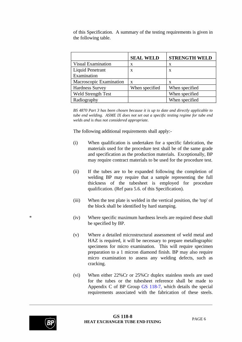
of this Specification. A summary of the testing requirements is given inthe following table.
SEAL WELD STRENGTH WELDVisual Examination x xLiquid PenetrantExamination
x x
Macroscopic Examination x xHardness Survey When specified When specifiedWeld Strength Test When specifiedRadiography When specified
BS 4870 Part 3 has been chosen because it is up to date and directly applicable totube end welding. ASME IX does not set out a specific testing regime for tube endwelds and is thus not considered appropriate.
The following additional requirements shall apply:-
(i) When qualification is undertaken for a specific fabrication, thematerials used for the procedure test shall be of the same gradeand specification as the production materials. Exceptionally, BPmay require contract materials to be used for the procedure test.
(ii) If the tubes are to be expanded following the completion ofwelding BP may require that a sample representing the fullthickness of the tubesheet is employed for procedurequalification. (Ref para 5.6. of this Specification).
(iii) When the test plate is welded in the vertical position, the 'top' ofthe block shall be identified by hard stamping.
* (iv) Where specific maximum hardness levels are required these shallbe specified by BP.
(v) Where a detailed microstructural assessment of weld metal andHAZ is required, it will be necessary to prepare metallographicspecimens for micro examination. This will require specimenpreparation to a 1 micron diamond finish. BP may also requiremicro examination to assess any welding defects, such ascracking.
(vi) When either 22%Cr or 25%Cr duplex stainless steels are usedfor the tubes or the tubesheet reference shall be made toAppendix C of BP Group GS 118-7, which details the specialrequirements associated with the fabrication of these steels.
GS 118-8HEAT EXCHANGER TUBE END FIXING
PAGE 7
Particular attention is drawn to paragraph C3.1 which requireseach specific duplex alloy to be separately qualified. Themetallurgical qualification and the hardness determinationsdetailed in paragraphs C3.3 and C3.5 shall form an integral partof the procedure qualification. Any need for corrosion testingto paragraph C3.7 as part of the procedure qualification shall bespecifically identified by BP.
(vii) When either titanium or zirconium are used for the constructionof the heat exchanger reference shall be made to therequirements detailed in Appendix D of BP Group GS 118-7.
4.6 Welder Qualifications
Welders and automatic welding operators shall be qualified inaccordance with BS 4871, Part 3 or equivalent, except that specificqualification is required for each grade of duplex stainless steel,titanium and zirconium.
Welders and automatic welding operators shall weld an agreed qualitycontrol test piece at regular intervals during the production welding oftitanium or zirconium, see Appendix D, paragraph D5 of BP Group GS118-7.
4.7 Tube Location For Welding
Accurate fit-up and intimate contact between the tube and tubesheet isessential for the achievement of consistently high quality joints. This isparticularly the case with automatic welding.
Fit-up may be assisted by light expansion of the tube ends. This may beachieved by the use of taper expanders or specially designed punches.
Any expansion prior to welding must be carefully controlled since if the tubes aretoo tightly expanded gases can only escape through the joint gap and this maycause weld metal porosity.

GS 118-8HEAT EXCHANGER TUBE END FIXING
PAGE 8
4.8 Preheat
For guidance, pre-heat temperatures are proposed for the materialslisted in the following table:-
Material Pre-heat temperature °CCarbon steels with> 0.25% C 50-100°CAlloy steels with up to 2%Cr
100°C minAlloy steels with2%-6%Cr 200°C min
Other alloys do not in general require preheating.
A wide range of carbon and carbon manganese steels, low alloy steels, austeniticand duplex stainless steels nickel alloys and other non ferrous materials are used inheat exchanger applications. Many of these materials may be welded without theneed for preheating.
Any specific need for the application of preheat shall be established aspart of the welding procedure qualification test.
Welding should not take place when either condensed moisture ispresent on the components or the ambient temperature is below 5°C.
Although the parent materials selected for a given application would perhapsrequire preheating when welded with a nominally matching composition filler,changing the filler wire to an austenitic stainless steel or nickel based material mayallow either the preheat temperature to be reduced or the preheat to be removed.The use of an automatic rather than manual welding process may also allowreduction or removal of the preheat.
When preheating is applied and it is necessary to interrupt the weldingthe assembly shall be insulated and allowed to cool slowly. Beforewelding is resumed, the assembly shall be brought back to the requiredpreheat temperature.
On completion of welding the assembly shall again be allowed to coolslowly as above.
Electrical pre-heating shall be used whenever possible. Fixed gasburners of suitable design giving a soft diffused flame may be used forpreheating and maintaining the preheat, provided that an adequatedegree of control can be demonstrated.
GS 118-8HEAT EXCHANGER TUBE END FIXING
PAGE 9
4.9 Post Weld Heat Treatment (PWHT)
* The application of PWHT to tubesheet assemblies requires particularlycareful control and support to ensure even heating and avoid distortionof the tubes. Therefore it can be beneficial to consider measures thatwill avoid PWHT. For example, the use of a clad tubesheet may allowfabrication without the need for PWHT of the final assembly. In theabsence of suitable clad material, the application of weld overlay to thetubesheet may be considered, allowing PWHT of the tubesheet prior todrilling and tube end welding. Tube selection should also take intoaccount the need to avoid PWHT.
When PWHT is unavoidable, procedures detailing tube bundle support,thermocouple locations, heating and cooling rates, and soak times shallbe submitted for the approval of BP.
The avoidance of PWHT during fabrication also considerably enhancesthe ability to repair the tube end welds on-site.
4.10 Welding
The tubes shall be welded to the tubesheet using the qualified andapproved procedure.
All tubes shall be welded individually. Procedures such as 'figure 8'welding and other complex welding patterns are not recommended.
The tube joints shall be welded in such a manner as to minimisedistortion of the tube sheet. Unless otherwise agreed with BP, wheremanual multi-run welds are used, no second run shall be deposited untilthe first run has been completed, cleaned as necessary and the weldvisually examined, (Ref para 4.13. of this Specification).
An intermediate low pressure air test or dye penetrant test may berequired by BP, (Ref para 6.1. of this Specification).
An intermediate low pressure air test or dye penetrant test after the first weld passensures that any defects that may give rise to leakage are detected at an early stagein manufacture. It also ensures that no attempt is made to make a two pass weld inonly one run.
4.11 Quality Control During Welding
The manufacturing and quality control procedures shall ensure that allwelding is adequately monitored. Equipment checks shall take placeprior to the start of each shift of production welding and at regularintervals during the course of production. The objective of thesechecks is to ensure that all welding is performed in accordance with thequalified and approved procedure.

GS 118-8HEAT EXCHANGER TUBE END FIXING
PAGE 10
4.12 Production Control Test Blocks
* When specified by BP, a sample tube end weld shall be made at thecommencement of each shift employing a test block identical to thatemployed for the welding procedure qualification test (see Appendix Dof this Specification).
This weld shall be visually examined before production welding startsand, if found unsatisfactory, the cause shall be established and the testrepeated prior to the commencement of production.
The production control test blocks shall be sectioned and checked atagreed intervals to ensure that the specified requirements in terms ofweld throat thickness, penetration, profile, ductility and hardness aremet.
If the results of these tests are unsatisfactory, production welding shallcease. The cause shall be established and any sub-standard productionwelds rectified to the satisfaction of BP.
Production control test blocks should be specified for all critical heat exchangersand when unfamiliar materials or automatic welding techniques are being used.
4.13 Cleaning and Inspection
* All cleaning and inspection activities shall be undertaken in accordancewith documented procedures submitted in advance by the vendor forapproval by BP. All NDT procedures shall be submitted to BP forreview prior to the commencement of welding.
After welding, the face of the tubesheet, the welds and the tube bore toa distance of at least 25 mm beyond the fusion line should be cleanedand examined visually for surface defects. Defects such as weldspatter, surface breaking porosity, slag deposits, lack of fusion andcracks are unacceptable and shall be rectified in accordance withSection 7 of this Specification.
Any over-run or spillage of weld metal into the tube bore which will bedetrimental to subsequent expansion or exceeds 5% of the borediameter at any one location shall be carefully removed.
Where a more searching examination is required, dye penetrant testingmay be specified by BP.
Radiographic examination shall be required for backface welds,although alternative NDT techniques may be proposed forconsideration by BP.

GS 118-8HEAT EXCHANGER TUBE END FIXING
PAGE 11
When critical heat exchangers are being fabricated, it is essential that tube endwelding and inspection progress together to an agreed programme, e.g. each shiftof tube end welding should be subject to inspection before further welds are made.This approach will ensure that any short comings in weld quality are identified atan early stage and that the situation can be rectified before it escalates. Forbackface welding the progressive assembly of the unit will dictate the welding andNDT sequence.
All inspection personnel shall have relevant experience which must bedocumented in the manufacturer's quality system. NDT operatives shallpossess the relevant level of PCN qualification.
5. TUBE EXPANSION
5.1 General
The expanded zone shall lie at least 19 mm from the weld root (if thetubes are welded) and at least 3 mm from the back of the tube sheet. A50 mm length expansion is normally sufficient. Tube expansion shall becarefully controlled to avoid expansion beyond the tubesheet.
The equipment used for tube expansion should be either of the mandreland parallel roller type, or the hydroswage type.
The vendor shall provide a procedure for the strength expansion oftubes for review by BP prior to commencement of fabrication.
5.2 Roller Expansion
Roller expanders should incorporate limiting controls to give apredetermined amount of tube wall thinning, i.e. controlled torqueequipment should be employed. The tube expander rolls should haveradiused ends.
Two 3 mm (0.125 in) wide x 1.5mm (0.064 in) deep grooves are normally used forroller expansion.
5.3 Hydroswaging
A special testing programme is necessary for each material combinationto ensure that hydroswaging is fully effective. Particular attention isdrawn to the need to allow sufficient time for the metal to flow into theexpansion grooves.
The groove detail for hydroswaging is different from that used in roller expansion.Grooves 5 mm (0.200 in)wide x 0.8 mm (0.032 in) deep are used for hydroswaging.

GS 118-8HEAT EXCHANGER TUBE END FIXING
PAGE 12
5.4 Wall Thinning
The amount of tube wall thinning for strength expansion shouldnormally be 5-7% of the original tube wall thickness. The machinesettings to achieve this thinning shall be determined and checked duringprocedure testing by measurements as follows:-
Diameter of tube hole: DMean outside diameter of tube: dInside diameter of tube after expansion: TInside diameter of tube before expansion: t
Tube wall thinning = ( ) ( )T t D d− − −
2
Measurements may be made by external and internal micrometer but boremeasurements may also be made by a Go-No-go plug gauge.
Where an expansion of 5-7% is not advisable, because of the materialtype or joint configuration, a suitable percentage expansion shall beagreed with BP.
Because of minute amounts of out-of-roundness in the tubes and variation inthickness, a range for the percentage wall thinning is given rather than a singlevalue. The range is more easily achieved with hydroswaging than roller expansion.
Theoretical studies have been made of the strength of tube to tubesheet attachmentsand one by Jawad, Clarkin and Schuessler is referenced in Appendix B.
5.5 Expansion After Welding
If the tubes are to be expanded after welding, the bores shall beinspected for weld spillage as detailed in para 4.13 of this Specification.It is permissible to dress the bores lightly in the weld area to avoidjamming of the rollers during subsequent expansion, but specificattention shall be given to ensure the minimum removal of metal fromthe bores of the tubes.
5.6 Expansion Procedure Test Block
* Expansion shall be performed in accordance with a documentedprocedure approved by BP.
When specified by BP a test block consisting of nine holes, 3x3, forsquare pitch arrangement or seven holes, 2,3,2, for triangular pitcharrangement shall be used to demonstrate the control and effectivenessof the expansion technique. Pressure or leak testing together withstrength testing and sectioning may be used to prove the test block.

GS 118-8HEAT EXCHANGER TUBE END FIXING
PAGE 13
When the tubes are to be expanded and welded the welding procedurequalification test block and the expansion test block may be combined.
5.7 Expansion Check
During production, BP may require a check to be made of theexpansion on selected tubes and the results recorded. This is for heatexchangers on critical applications.
Measurement by Go-No-go gauge is a quick way of checking that all tubes havebeen expanded by the correct amount.
6. LEAK DETECTION
6.1 Leak Detection of Welded or Welded and Expanded Tube Ends
Prior to the leak test, a dye penetrant check of all tube end welds shallbe made.
* When specified by BP, the final hydrostatic test shall be preceded by alow pressure air test or by a gas leak test. No liquid shall be applied tothe shell side of the tube sheet prior to any gas leak test.
Where manual multi-run tube-to-tubesheet welds are used for criticalduties, the leak test should be carried out on completion of the first run.
By agreement with BP, liquid penetrant testing may be substituted forlow pressure air testing or gas leak testing.
6.1.1 Air Testing
The assembly should be tested for leaks by applying a pressure of 0.5bar (ga) (7.25 psig). While the shell is under pressure, a soap detergentshall be used to indicate the escape of air from leaks.
The above pressure has been found to be the optimum for leak testing. Higherpressures should not be used because the air jet at a leak may blow the soapy wateraway making detection difficult.
6.1.2 Gas Leak Testing
* When specified by BP, a tracer gas leak test shall be used instead of theair test. The tracer gas is usually helium, but other gases may be usedsubject to BP approval.
6.1.3 Leak Investigation
All suspect weld locations shall be marked for repair.

GS 118-8HEAT EXCHANGER TUBE END FIXING
PAGE 14
In the event that more than 5% of the tube to tubesheet welds are foundto be defective a full investigation into the cause of the high incidenceof defects shall be conducted. Unless otherwise authorised by BP, thewhole of the tubesheet and all tubes shall be re-prepared and re-weldedat the vendor's cost.
6.2 Leak Detection of Expanded Only Tube Ends
* Where specified by BP, the assembly shall be leak tested in accordancewith the requirements of para. 6.1.1 and, if necessary, leaks shall beinvestigated and rectified as required in para. 6.1.3, before the finalpressure test.
7. REPAIRS
Prior to any repairs being undertaken the face of the tubesheet, thewelds and the internal surfaces of the tubes shall be thoroughly cleanedto a length of about 25 mm (1.0 in.) by a suitable method. Any greasethat may be present shall be removed either by the use of a chloride andsulphur free non-residue forming solvent or by steam jets.
The repair of leaks detected by hydrostatic testing may be complicatedduring rewelding by the boiling of entrapped water behind the weldwhich can cause weld metal porosity. Therefore, the heat exchangershall be drained and, if necessary, dried by hot air before any repairwelding is carried out.
Any leaks discovered shall be repaired to the original procedures takingcare not to over expand the tubes. Testing should be repeated until allfaults are remedied. Defective welds shall be completely removed tosound metal and repaired using the qualified WPS.
Care shall be taken not to over-expand the tubes as this can lead to tube failure.
8. PRESSURE TESTING
The final acceptance pressure test shall be conducted in accordancewith the applicable design code.
2% by volume of an approved wetting agent or detergent shall beadded to the test water. When austenitic stainless steels are being testedthe chloride content of the water shall not exceed 30 ppm.
Other test media may be specified by BP in special cases where watermay be unsuitable because of complexity of design, or for duty with

GS 118-8HEAT EXCHANGER TUBE END FIXING
PAGE 15
process fluids whose admixture with water is undesirable, e.g. SO2 orLPG. Such specifications will include the procedures to be used forfreeing the exchanger of the test medium prior to despatch from thesupplier's works.
After maintaining the specified pressure for a minimum period of 30minutes the welds and bores of the tubes shall be examined for leaks.The location of all leaks shall be marked on the tubesheet and recordedon a tubesheet drawing.
All leaks shall be repaired as described in Section 7 and the unit subjectto a repeat pressure test.
9. DRAINING AND DEWATERING
* The vessel shall be drained thoroughly after testing to avoid corrosionor microbial attack. Where specified by BP, a dewatering fluidapproved by BP should be used. Any passivation treatments shall bespecified by BP.
If the heat exchanger is required to be completely dry and whenspecified by BP, the assembly should be heated by an appropriatemethod to a temperature that causes no damage to the unit, but issufficiently high to remove all water, particularly from the interspacesbetween the tubes and the tube sheet.

GS 118-8HEAT EXCHANGER TUBE END FIXING
PAGE 16
10. INSPECTION
A summary of the inspection activities specified in this Specification is given in thefollowing table:-
SECTION INSPECTION ACTIVITY APPLICABILITY4.4 Approve tube end WPS TEW4.5 &App C
Inspect welding procedure qualification test blocks.Witness/approve testing and results.
TEW
5.1 Approve tube expansion procedure EXP5.6 &App C
Inspect expansion procedure test blockswitness/approve testing and result
EXP
4.6 &App C
Inspect welder/welding operator qualification test blockswitness/approve testing and results
TEW
3.0 Inspect machining of tube sheet holes and grooves prior toassembly
*
3.0 Inspect cleanliness of tubes and tube sheet prior to assembly *3.0 Inspect cleanliness of tubes and tube sheets prior to welding TEW4.12 Approve daily welding test blocks *4 & 5 Inspect during tube end welding and expansion for
compliance with proceduresTEW & EXP
5.1 Examine expanded tubes for damage and over expansion EXP5.7 Review report on % expansion - check against test block
resultsEXP
4.11 Visually inspect tube end welds TEW6.1 Witness liquid penetrant examination of root and final passes *6.1.1 Witness leak testing after expansion and tube end welding *7. Inspect repairs to this standard8. Witness final pressure test9. Confirm that heat exchanger has been dewatered/dried as
specified
SUMMARY OF INSPECTION ACTIVITIES
TEW - Applies only to tube end welding
EXP - Applies only to expansion
* - Applies where specified

GS 118-8HEAT EXCHANGER TUBE END FIXING
PAGE 17
APPENDIX A
DEFINITIONS AND ABBREVIATIONS
Definitions
Standardised definitions may be found in the BP Group RPSEs Introductory Volume.
Abbreviations
GMAW Gas Metal Arc Welding
GTAW Gas Tungsten Arc Welding
HAZ Heat Affected Zone
NDT Non-destructive Testing
PCN Personnel Certification in Non-destructive testing
PQR Procedure Qualification Record
PWHT Post Weld Heat Treatment
SMAW Shielded Metal Arc Welding
TEMA Tubular Exchanger Manufacturers Association
WPS Welding Procedure Specification

GS 118-8HEAT EXCHANGER TUBE END FIXING
PAGE 18
APPENDIX B
LIST OF REFERENCED DOCUMENTS
A reference invokes the latest published issue or amendment unless stated otherwise.
Referenced standards may be replaced by equivalent standards that are internationally orotherwise recognised provided that it can be shown to the satisfaction of the purchaser'sprofessional engineer that they meet or exceed the requirements of the referenced standards.
ASME VIII:1995 ASME Boiler and Pressure Vessel Code - Section VIII Division 1
ASME IX ASME Boiler and Pressure Vessel Code - Section IX Welding andBrazing qualifications
BS 5500:1997 Unfired fusion welded pressure vessels
BS 4870:1985 Approval testing of welding proceduresPart 3: Arc welding of tube to tube-plate joints in metallic materials
BS 4871:1985 Approval testing of welders working to approved welding proceduresPart 3: Arc welding of tube to tube-plate joints in metallic materials
TEMA Standards of Tubular Exchanger Manufacturers Association
ISO 9001 Quality systems - Model for quality assurance in design/development,production, installation and servicing.
BP GS 118-7 Fabrication of Pipework to ANSI B31.3 Part 3: Austenitic and Duplexsteel pipework, Cupro-nickel and Nickel based alloy pipework.
ASME Pressure Vessels and Piping Conference, Chicago 1986: Evaluation of tube-to-tubesheet junctions, by Jawad, Clarkin and Schuessler, PVP-Vol.105.
GS 118-8HEAT EXCHANGER TUBE END FIXING
PAGE 19
APPENDIX C
TYPICAL JOINT DETAILS
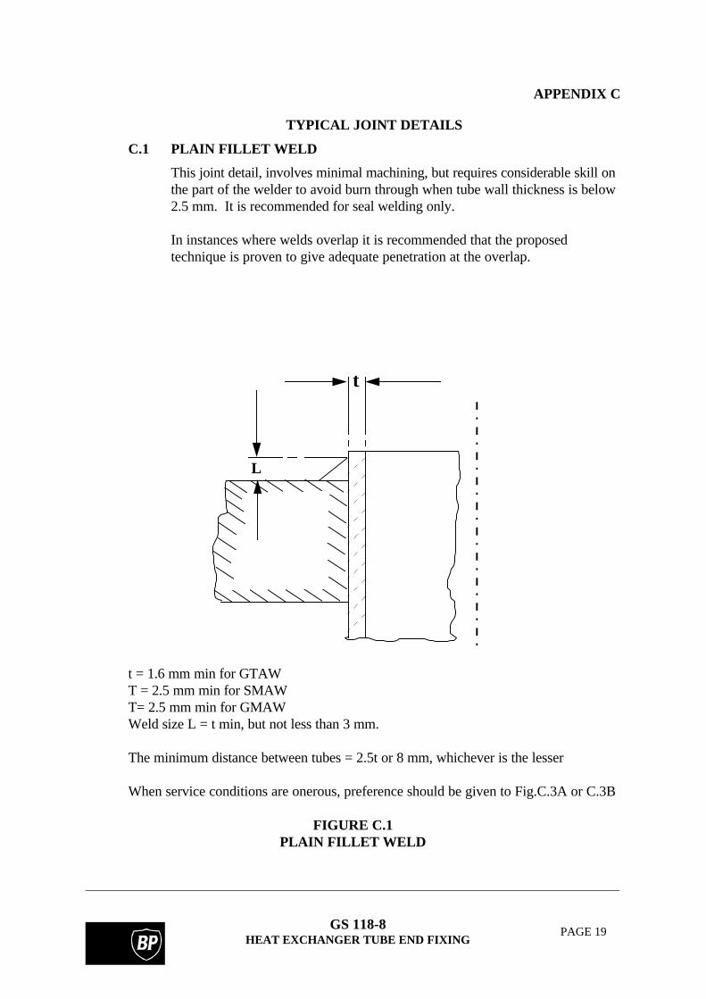
C.1 PLAIN FILLET WELD
This joint detail, involves minimal machining, but requires considerable skill onthe part of the welder to avoid burn through when tube wall thickness is below2.5 mm. It is recommended for seal welding only.
In instances where welds overlap it is recommended that the proposedtechnique is proven to give adequate penetration at the overlap.
L
t
t = 1.6 mm min for GTAWT = 2.5 mm min for SMAWT= 2.5 mm min for GMAWWeld size L = t min, but not less than 3 mm.
The minimum distance between tubes = 2.5t or 8 mm, whichever is the lesser
When service conditions are onerous, preference should be given to Fig.C.3A or C.3B
FIGURE C.1PLAIN FILLET WELD

GS 118-8HEAT EXCHANGER TUBE END FIXING
PAGE 20
C.2 RECESSED TUBE
This joint detail involves minimal machining. It is recommended for sealwelding.
Where the tube wall thickness is a minimum of 3 mm and access is notrestricted the recessed tube joint detail is applicable to the SMAW process. TheGTAW process is applicable to this joint detail down to a tube wall thicknessof 1.6 mm.
t
F
For GTAW, and F = 0.7t min. t = 2.5 mm max. The tube may be flush or up to 1.5mm max below tube surface.
For GMAW and SMAW, and F = 0.7t min. t = 3 mm min. .
FIGURE C.2
RECESSED TUBE
GS 118-8HEAT EXCHANGER TUBE END FIXING
PAGE 21
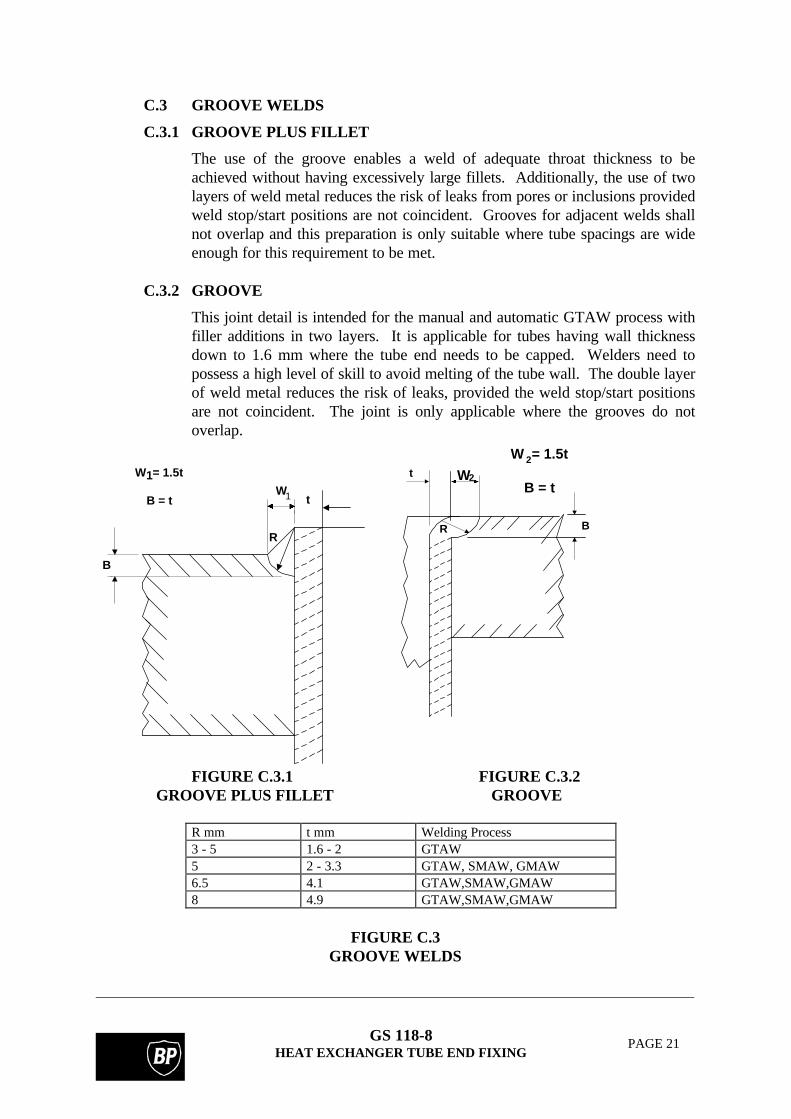
C.3 GROOVE WELDS
C.3.1 GROOVE PLUS FILLET
The use of the groove enables a weld of adequate throat thickness to beachieved without having excessively large fillets. Additionally, the use of twolayers of weld metal reduces the risk of leaks from pores or inclusions providedweld stop/start positions are not coincident. Grooves for adjacent welds shallnot overlap and this preparation is only suitable where tube spacings are wideenough for this requirement to be met.
C.3.2 GROOVE
This joint detail is intended for the manual and automatic GTAW process withfiller additions in two layers. It is applicable for tubes having wall thicknessdown to 1.6 mm where the tube end needs to be capped. Welders need topossess a high level of skill to avoid melting of the tube wall. The double layerof weld metal reduces the risk of leaks, provided the weld stop/start positionsare not coincident. The joint is only applicable where the grooves do notoverlap.
B
R
Wt1
W = 1.5t
B = t
1 W2t
R B
W = 1.5t
B = t
2
FIGURE C.3.1 FIGURE C.3.2 GROOVE PLUS FILLET GROOVE
R mm t mm Welding Process3 - 5 1.6 - 2 GTAW5 2 - 3.3 GTAW, SMAW, GMAW6.5 4.1 GTAW,SMAW,GMAW8 4.9 GTAW,SMAW,GMAW
FIGURE C.3GROOVE WELDS

GS 118-8HEAT EXCHANGER TUBE END FIXING
PAGE 22
C.4 CASTELLATED WELD PREPARATION
With tubes of a wall thickness of 2 mm or less, this joint detail is adoptedwhere there is a serious risk of tube wall burn through. It is intended for themanual and automatic GTAW processes with or without filler additions.However, with manual welding it can be difficult to control the penetration inorder to achieve a strength weld and the detail is not recommended where theweld is expected to corrode in service.
The pitch of the tubes should be such that a projection can be formed roundeach hole, but the intersection of grooves is unimportant.
t
tW =
D
W
D = 1t to 2t
t = 2mm or less
Notes:
1) GTAW process only
2) It is advisable to examine the tubesheet surface for laminations before machining.
3) Set-up of tube shall be flush with castellation.
4) These details are recommended for use when it is required to minimise the deformation ofthe tubesheet due to welding, e.g. clad tubesheet.
FIGURE C.4
CASTELLATED WELD PREPARATION
GS 118-8HEAT EXCHANGER TUBE END FIXING
PAGE 23
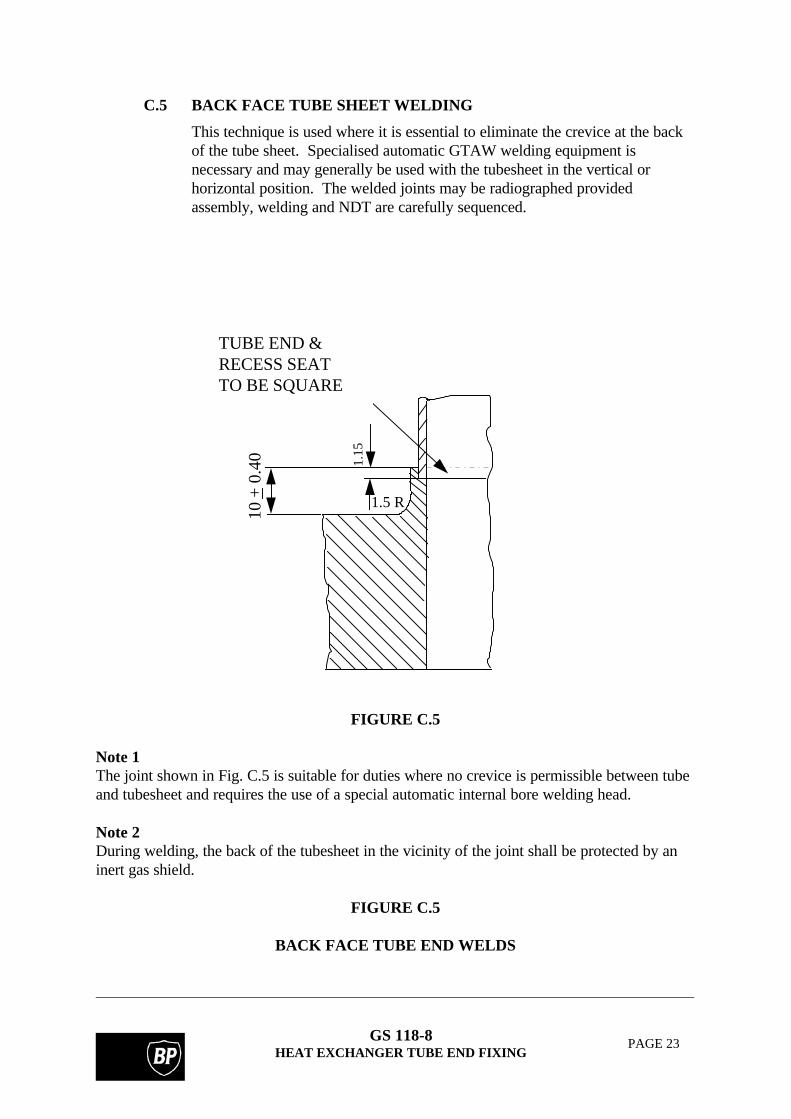
C.5 BACK FACE TUBE SHEET WELDING
This technique is used where it is essential to eliminate the crevice at the backof the tube sheet. Specialised automatic GTAW welding equipment isnecessary and may generally be used with the tubesheet in the vertical orhorizontal position. The welded joints may be radiographed providedassembly, welding and NDT are carefully sequenced.
TUBE END &RECESS SEATTO BE SQUARE
1.15
1.5 R
10 +
0.4
0
FIGURE C.5
Note 1The joint shown in Fig. C.5 is suitable for duties where no crevice is permissible between tubeand tubesheet and requires the use of a special automatic internal bore welding head.
Note 2During welding, the back of the tubesheet in the vicinity of the joint shall be protected by aninert gas shield.
FIGURE C.5
BACK FACE TUBE END WELDS

GS 118-8HEAT EXCHANGER TUBE END FIXING
PAGE 24
C.6 DESIGN TO AVOID HOT HYDROGEN SULPHIDE CORROSION
The joint details shown are used at the hot (front) tubesheet on condensers andwaste heat boilers on sulphur units at temperatures of approximately 420°C.Each combines strength with good heat transfer thereby minimising corrosionfrom hot hydrogen sulphide.
8
R = 3
300
5
6
1mm
max
1mm
10
R = 3
30 0
9
Note: Welding may be by SMAW, GTAW or GMAW.
FIGURE C.6
DESIGN TO AVOID HOT HYDROGEN SULPHIDE CORROSION

GS 118-8HEAT EXCHANGER TUBE END FIXING
PAGE 25
APPENDIX D
WELD PROCEDURE AND WELDER QUALIFICATION TEST BLOCKS
TUBE SPACINGWELD DETAIL TOBE THAT USED ONACTUAL HEATEXCHANGER
35mm
35mm
35mm
35mm
SECTION OF TUBES& TUBE SHEET OFSAME MATERIALSIZE & THICKNESSTO BE USED ON ACTUAL HEATEXCHANGER
FIGURE D.1 TEST SPECIMEN FOR SQUARE PITCH
35mm
35mm
35mm
FIGURE D.2 TEST SPECIMEN FOR TRIANGULAR PITCH
Note: Full details are given in BS 4870 Part 3 and BS 4871 Part 3.


![[XLS] · Web view8 5573 8 5038.5 8 12250 8 8229.5499999999993 8 8662.33 7 5265.5 8 8103 8 8647.35 8 4093 7 5914 8 6425.5 8 10706.5 8 10000 8 10000 7 13325.27 8 6148 8 5453.5 8 7750](https://static.documents.pub/doc/80x56/5bd6d1de09d3f2e17c8bfdea/xls-web-view8-5573-8-50385-8-12250-8-82295499999999993-8-866233-7-52655.jpg)


