DEPARTMENT OF ELECTRONICS & COMMUNICATION GSM ARCHITECTURE Gyan Vihar School of Engineering & Technology Jagatpura, Jaipur A Report on “GSM ARCHITECTURE” Based on the training at Session (2010-2011) Rajasthan Technical University, Kota B.TECH-2007 Submitted To : Submitted By Mr. Rashid Hussain Puneet Gupta hod (e&c deptt.) elelctronics &comm. 1
Transcript
DEPARTMENT OF ELECTRONICS & COMMUNICATION GSM ARCHITECTURE
Gyan Vihar School of Engineering & Technology
Jagatpura, Jaipur
A
Report on
“GSM ARCHITECTURE”Based on the training at
Session
(2010-2011)
Rajasthan Technical University, Kota
B.TECH-2007
Submitted To : Submitted By Mr. Rashid Hussain Puneet Gupta hod (e&c deptt.) elelctronics &comm.
INDEX
1
DEPARTMENT OF ELECTRONICS & COMMUNICATION GSM ARCHITECTURE
SR.NO. CONTENTS PAGE NO.
1. Certificate 1.................................................................................. 42. Certificate 2.................................................................................. 53. Acknowledgement........................................................................ 64. Preface................................................................................ .......... 75. Declaration.................................................................................... 86. Company Profile........................................................................... 9-107. History of GSM............................................................................ 11-128. GSM System Specification........................................................... 13-14
i. Frequency Ranges9. GSM Abbreviations...................................................................... 15-1910. Some Facts about GSM................................................................ 20
i. Access Methodii. Narrow Band Vs Broad Band
iii. Performance Characteristics Of GSM11. GSM Services................................................................................ 21-22
i. Telephony servicesii. Bearer or data services
iii. Supplementary Services12. GSM- Basic Building Blocks......................................................... 23-28
i. Mobile Station (MS)ii. Base station (BS)
iii. Mobile Services Switching Centreiv. Operation And Maintenance Centre
DEPARTMENT OF ELECTRONICS & COMMUNICATION GSM ARCHITECTURE
vi. LAIvii. CGI
viii. BSIC16. Control Channels.............................................................................. 3617. Location Update............................................................................... 37-3818. Attaching & Detaching To the Network......................................... 39
i. IMSI Attachii. IMSI Detach
iii. Implicit Detachiv. MS Purging
19. Call Flow.......................................................................................... 40-43i. Call Flow From an MS
1. Originating Call Flowii. Call to an MS
1. Terminating Call Flow20. Handovers......................................................................................... 4421. Advantages of GSM.......................................................................... 4522. GSM Applications............................................................................. 4523. Future Of GSM.................................................................................. 45
DEPARTMENT OF ELECTRONICS & COMMUNICATION GSM ARCHITECTURE
1. Certificate(ii)4
DEPARTMENT OF ELECTRONICS & COMMUNICATION GSM ARCHITECTURE
This is authorized that “PUNEET GUPTA” completed his training from 12th MAY 2010 to 18th JUNE 2010 in my allowance in partial fulfillment for the Degree of BACHELOR OF ENGINEERING.
During this period he has worked on “GSM Architecture” at AIRTEL, Gurgaon.
Mrs. Shweta Sharda Mr. Rashid Hussain
(Presentation Incharge) Head Of Dept.
Electronics & Communication
5
DEPARTMENT OF ELECTRONICS & COMMUNICATION GSM ARCHITECTURE
2. Acknowledgement
“I believe that hard work is the only way to success to achieve something worthy.”
As a part of B.TECH (Elect. & Comm.) VIIth Semester Curriculum of Rajasthan Technical University, I
have completed summer practical training in GSM Architecture.
At the outset of submission of this Project report, I express our deep sense of gratitude towards Mr. Rashid
Hussain H.O.D GVSET, JAIPUR for allowing me the opportunity to experience dynamic professional
environment
With feeling of immense gratitude and respect, I would
like to thank my guides Mr. Rajender Kumar, Mr. Kamal, Mr. Uday Sharma, and Mr Lalit for their
continuous support throughout this work, which has been a guiding spirit and lent a helping hand at every
step of the training. I would also thank one and all who helped me in doing this work either directly or
indirectly.
I am grateful to my respected Circle Head Mr. Ravi Prakash and all the staff members of the AIRTEL,
Gurgaon, for their constant encouragement and all those who helped us directly or indirectly in our effort.
I would also like to thank all my friends who have helped, in one way or another, in the completion of this
report, and helped me better understand to my training.
PUNEET GUPTA
6
DEPARTMENT OF ELECTRONICS & COMMUNICATION GSM ARCHITECTURE
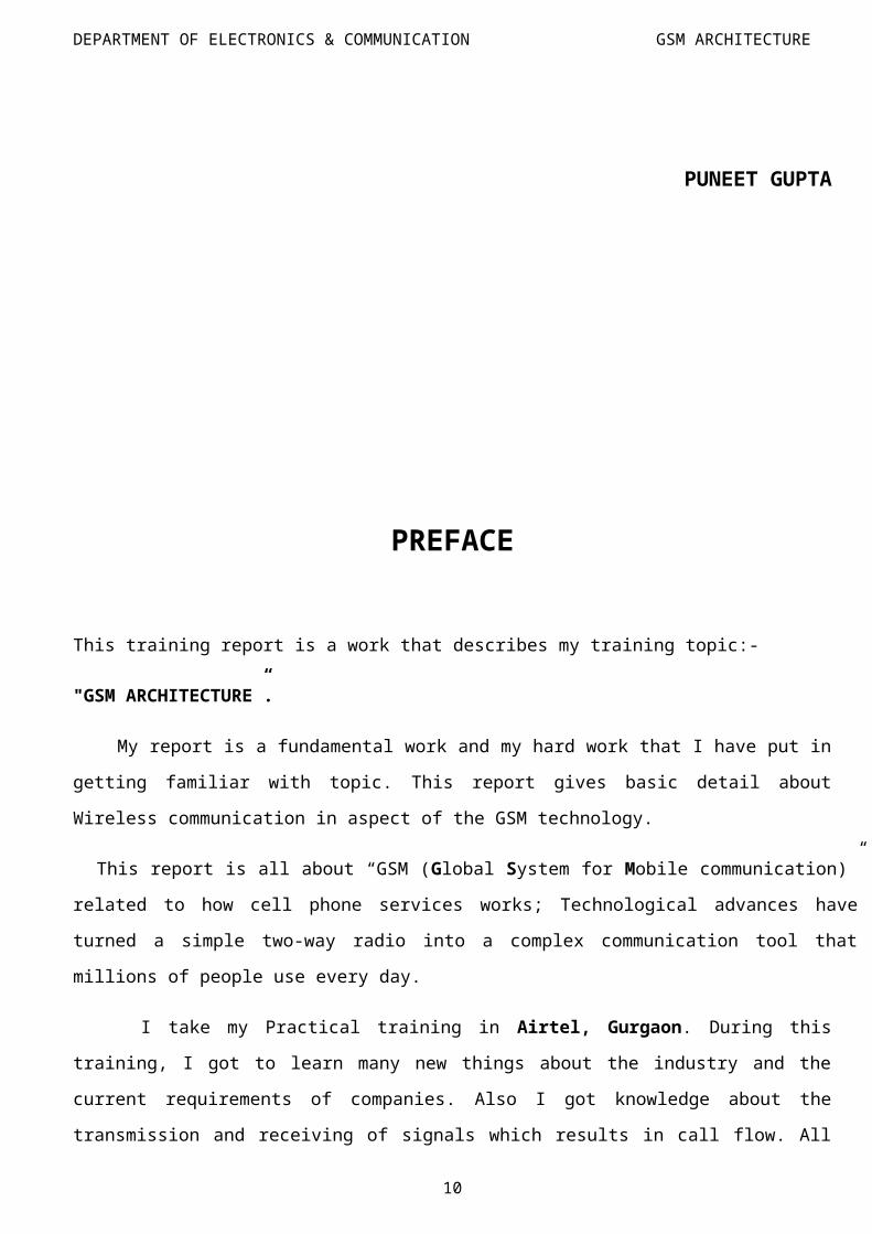
PREFACE
This training report is a work that describes my training topic:-
"GSM ARCHITECTURE”.
My report is a fundamental work and my hard work that I have put in getting familiar with topic. This
report gives basic detail about Wireless communication in aspect of the GSM technology.
This report is all about “GSM (Global System for Mobile communication)” related to how cell phone
services works; Technological advances have turned a simple two-way radio into a complex communication
tool that millions of people use every day.
I take my Practical training in Airtel, Gurgaon. During this training, I got to learn many new things
about the industry and the current requirements of companies. Also I got knowledge about the transmission
and receiving of signals which results in call flow. All this knowledge I got at BTS (Base Transceiver
System) which we generally known as mobile tower. This training proved to be a milestone in our
knowledge of present industry scenario and developing business in field of Telecommunication.
Every say and every moment was an experience in itself, an experience which theoretical study can’t
provide.
Training is essential to groom us for practical and professional environment that we are become part of in
our career.
PUNEET GUPTA
7
DEPARTMENT OF ELECTRONICS & COMMUNICATION GSM ARCHITECTURE
DECLARATION
I hereby declare that the project work entitled “ GSM (Global System on Mobile
communication) Architecture” is an authentic record of my own work carried out at Airtel, Gurgaon as
per the requirement of ONE month Industrial Training project for the award of degree of BACHELOR OF
TECHNOLOGY at Gyan Vihar School Of Engineering And Technology Jagatpura, Jaipur, under the
guidance of Mr. Rajender Kumar, Mr. Kamal, Mr. Uday Sharma, Mr Lalit during May 2010 to June
2010.
Place: - Gurgaon PUNEET GUPTA
Date:-18 -July -2010
It is certified that the above statement made by the student is correct to the best of our knowledge and
belief.
Date: - 18-July-2010 Training Incharge
Mr. Ravi Prakash
8
DEPARTMENT OF ELECTRONICS & COMMUNICATION GSM ARCHITECTURE
COMPANY PROFILE
Bharti Airtel Limited formerly known as Bharti Tele-Ventures LTD (BTVL) is an Indian company offering telecommunication services in 19 countries. The company is structured into four strategic business units - Mobile, Telemedia, Enterprise and Digital TV. The mobile business offers services in India, Sri Lanka and Bangladesh. The Telemedia business provides broadband, IPTV and telephone services in 89 Indian cities. The Digital TV business provides Direct-to-Home TV services across India. The Enterprise business provides end-to-end telecom solutions to corporate customers and national and international long distance services to telcos
Airtel is the largest wireless service provider in India, based on the number of customers as of June 30, 2010. It offers an integrated suite of telecom solutions to enterprise customers, in addition to providing long distance connectivity both nationally and internationally. It also offers DTH and IPTV Services. All these services are rendered under a unified brand “Airtel”.Airtel served an aggregate of 183,371,520 customers as of June 30, 2010.
ACHIEVMENTS
Bharti Airtel Achieves Gold Certification from Cisco India. With this, Bharti Airtel is the first Indian telecom service provider to achieve this certification.
It is known for being the first mobile phone company in the world to outsource everything except marketing and sales and finance.
Bharti Airtel has been ranked among the six best performing technology companies in the world by Business Week.
Bharti Airtel is the world's third largest, single-country mobile operator and fifth largest telecom operator in the world with a subscriber base of over 180 million.
Bharti Airtel announced that it would acquire 100% stake in Telecom Seychelles taking its global presence to 19 countries.
On May 18, 2010, 3G spectrum auction was completed and Airtel will have to pay the Indian government Rs. 12,295 crores for spectrum in 13 circles, the most amount spent by an operator in this auction.
Airtel is the market leader in India with a total of 133,619,705 out of 444,295,711 GSM mobile connections or 31.18% market share as of July 2010.
The Financial Times reported that Bharti was considering offering US$45 billion for a 100% stake in MTN, which would be the largest overseas acquisition ever by an Indian firm.
DEPARTMENT OF ELECTRONICS & COMMUNICATION GSM ARCHITECTURE
List of countries
Airtel operates in the following countries.
COUNTRY REMARKS
Bangladesh Warid Telecom International LLC, an Abu Dhabi based consortium, sold a majority 70% stake in the company to India's Bharti Airtel Limited for US$300 million.[1] Bharti Airtel Limited will take management control of the company and its board, and will relaunch the company's services under its own Airtel brand. The Bangladesh Telecommunication Regulatory Commission approved the deal on January 4, 2010. As of December, 2009 Warid has secured 2.99 million subscribers and is ranked fourth among the six operators of Bangladesh.
Ghana Airtel in Ghana has over 1 million customers.
India Airtel in India is the market leader with over 100 million customers.
Kenya Airtel in Kenya has 2,418,000 customers with 17% market share.
Nigeria Airtel in Nigeria is the market leader with a 68% market share.
Sri Lanka Airtel in Sri Lanka is the market leader with a 38% market share
Uganda Airtel in Uganda stands as the no. 2 operator with a market share of 38%
Some other countries where AIRTEL has spread its wings are:-
1.Burkina2.Faso3.Democratic Republic of the Congo4.Chad5.Gabon6.Ghana7.Madagascar8.Tanzania9.Zambia10. Sierra Leone11. Malawi
DEPARTMENT OF ELECTRONICS & COMMUNICATION GSM ARCHITECTURE
HISTORY OF GSMThe idea of cell-based mobile radio systems appeared at Bell Laboratories (in USA) in the early 1970s. However, mobile cellular systems were not introduced for commercial use until the 1980s. During the early 1980s, analog cellular telephone systems experienced a very rapid growth in Europe, particularly in Scandinavia and the United Kingdom, but also in France and Germany. Each country developed its own system, which was incompatible with everyone else's in equipment and operation. This was an undesirable situation, because not only was the mobile equipment limited to operate only within the boundaries of each country, which in a unified Europe were increasingly unimportant, but there was also a very limited market for each mobile equipment was limited, so economies of scale, and the subsequent savings, could not be realized.
In order to overcome these problems, the Conference of European Posts and Tele Communication (CEPT) formed, in 1982, the Groupe Spécial Mobile (GSM) in order to develop a pan-European mobile cellular radio system (the GSM acronym became later the acronym for Global System for Mobile communications). The standardized system had to meet certain criteria:
Good subjective speech quality
Support for international roaming
Ability to support handheld terminals
Support for range of new services and facilities
Spectral efficiency
Low mobile and base stations costs
Compatibility with other systems such as Integrated Services Digital Network (ISDN)
In 1989, the responsibility for the GSM specifications passed from the CEPT to the European Telecommunications Standards Institute (ETSI). The commercial use of GSM started around mid-1991, and by 1993 there were 36 GSM networks in 22 countries. Although standardized in Europe, GSM is not only a European standard. Over 200 GSM networks (including DCS1800 and PCS1900) are operational in 110 countries around the world. In the beginning of 1994, there were 1.3 million subscribers worldwide, which had grown to more than 5.4 million subscribers by October 1997. With North America making delayed entry into the GSM field with a derivative of GSM called PCS1900, GSM systems exist on every continent, and the acronym GSM now aptly stands for Global System for Mobile Communications
Developed by Group Special Mobile (founded in 1982) which was an initiative of CEPT (Conference of European Post and Telecommunication)?
Aim: To replace the incompatible analogue system. Presently the responsibility of GSM standardization resides with special mobile group under
ETSI (European Telecommunication Standards Institute) Full set of specification phase -1 become available in 1990 Under ETSI, GSM is named as “Global System for Mobile Communication”. Today many providers all over the world use GSM (more than 135 countries worldwide). More than 1300 million subscribers in world and 45 million subscribers in India.
11
DEPARTMENT OF ELECTRONICS & COMMUNICATION GSM ARCHITECTURE
GSM – BASIS OF CURRENT MOBILE SYSTEM
GSM today means Global System for Mobile Communication is a second generation cellular standard developed to cater voice services and data delivery using digital modulation
Introduction by the European telephone exchange offices Uses the frequency ranges of 900, 1800 and 1900 MHz Voice (bandwidth 3.1 KHz) and data connections with up to 9.6 Kbit/s (enhancement: 14.4
Kbit/s). Short Message Service – SMS. Cell structure for a complete coverage of regions (100 – 500 m per cell in cities, up to 35 Km
on country side).
12
DEPARTMENT OF ELECTRONICS & COMMUNICATION GSM ARCHITECTURE
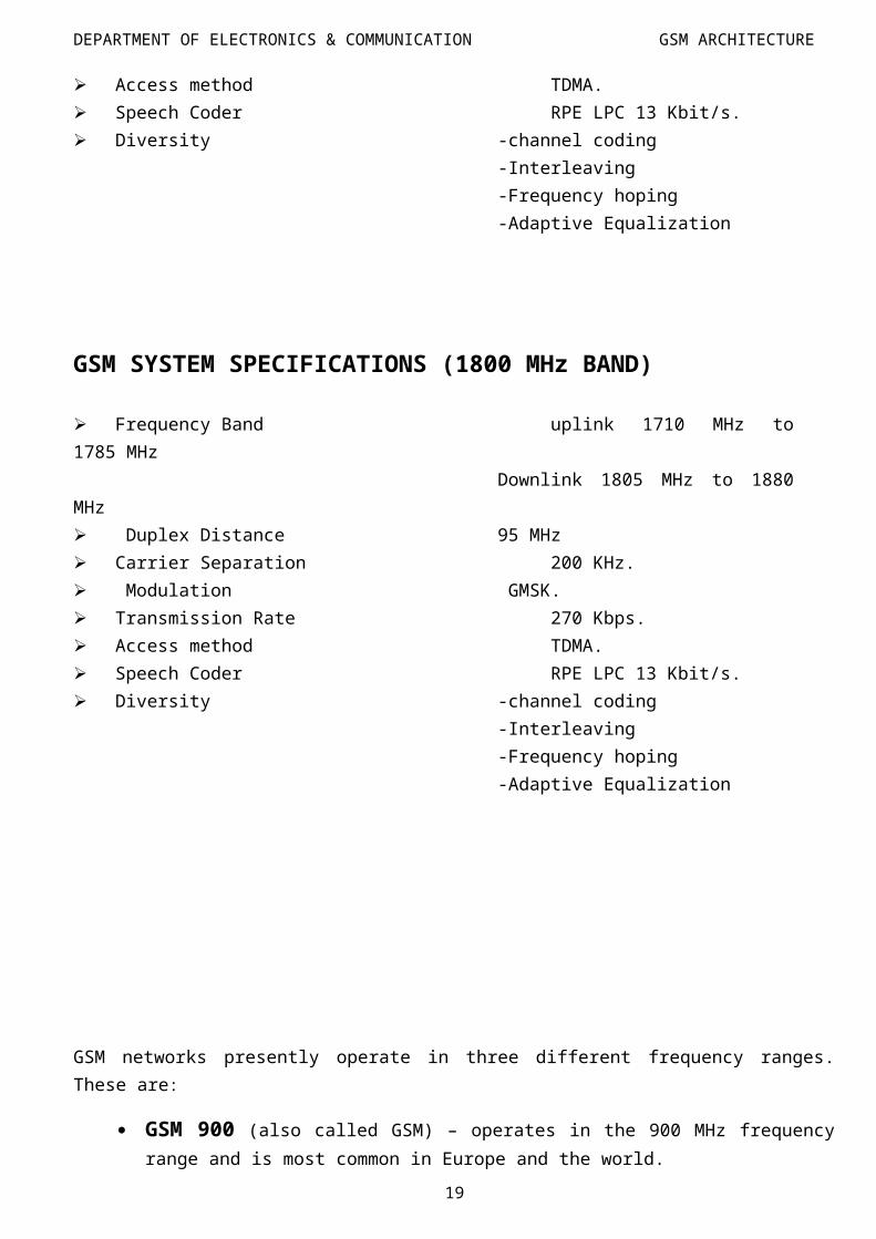
GSM SYSTEM SPECIFICATIONS
GSM SYSTEM SPECIFICATIONS (900 MHz BAND)
Frequency Band uplink 890 MHz to 915 MHzDownlink 935 MHz to 960 MHz
DEPARTMENT OF ELECTRONICS & COMMUNICATION GSM ARCHITECTURE
GSM networks presently operate in three different frequency ranges. These are:
GSM 900 (also called GSM) – operates in the 900 MHz frequency range and is most common in Europe and the world.
GSM 1800 (also called PCN (Personal Communication Network), and DCS 1800) – operates in the 1800 MHz frequency range and is found in a rapidly-increasing number of countries including France, Germany, Switzerland, the UK, and Russia. A European Commission mandate requires European Union members to license at least one DCS 1800 operator before 1998.
GSM 1900 (also called PCS (Personal Communication Services), PCS 1900, and DCS 1900) – the only frequency used in the United States and Canada for GSM. Note that the terms PCS is commonly used to refer to any digital cellular network operating in the 1900 MHz frequency range, not just GSM.
14
DEPARTMENT OF ELECTRONICS & COMMUNICATION GSM ARCHITECTURE
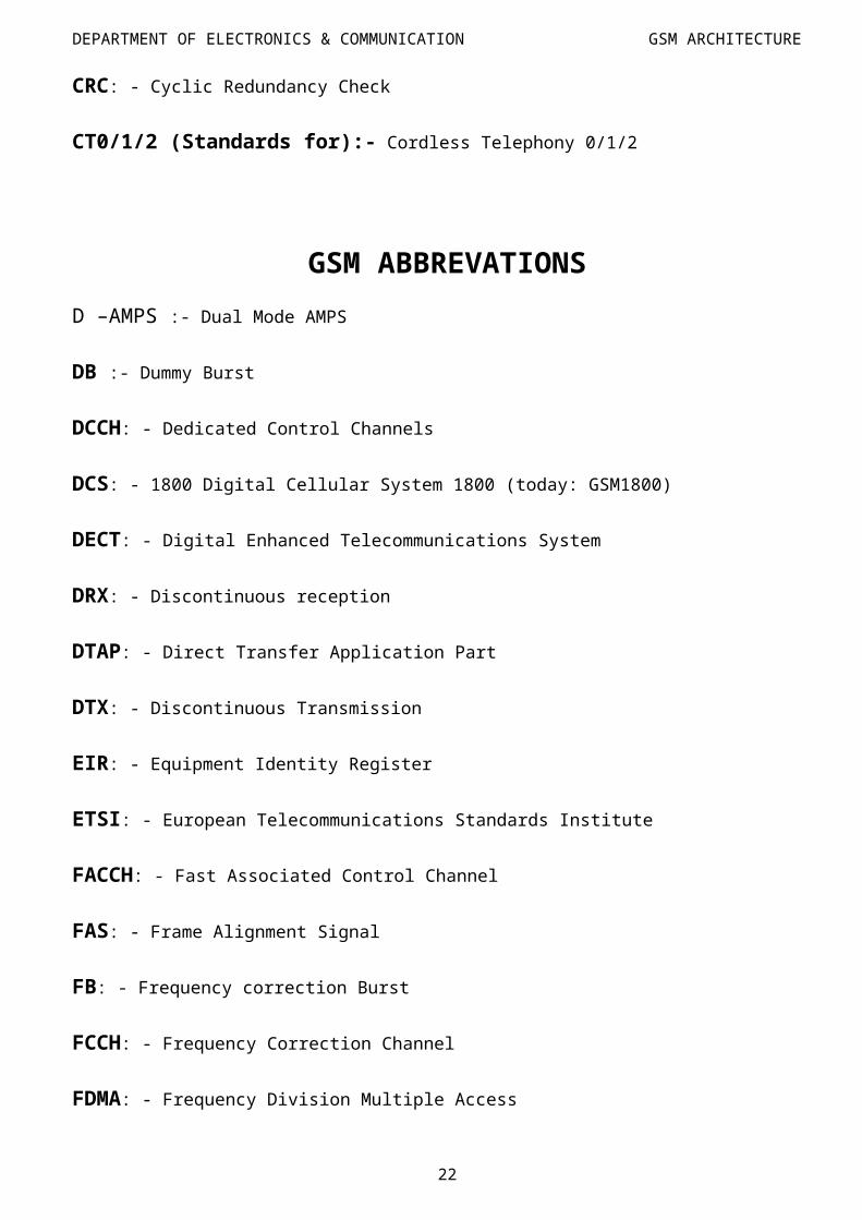
GSM ABBREVATIONS
AB:-Access Burst
AGCH:-Access Grant Channel
AIS:-Alarm Indication Signal
AMPS:-Advanced Mobile Telephone Service
Auk:-Authentication Centre
BCCH: - Broadcast Control Channel
BCH: - Broadcast Channels
BER: - Bit Error Rate
BERT: - Bit Error Rate Test
BSC: - Base Station Controller
BSSAP: - Base Station System Application Part
BSSMAP: - Base Station Management Application Part
DEPARTMENT OF ELECTRONICS & COMMUNICATION GSM ARCHITECTURE
GSM ABBREVATIONS
D –AMPS :- Dual Mode AMPS
DB :- Dummy Burst
DCCH: - Dedicated Control Channels
DCS: - 1800 Digital Cellular System 1800 (today: GSM1800)
DECT: - Digital Enhanced Telecommunications System
DRX: - Discontinuous reception
DTAP: - Direct Transfer Application Part
DTX: - Discontinuous Transmission
EIR: - Equipment Identity Register
ETSI: - European Telecommunications Standards Institute
FACCH: - Fast Associated Control Channel
FAS: - Frame Alignment Signal
FB: - Frequency correction Burst
FCCH: - Frequency Correction Channel
FDMA: - Frequency Division Multiple Access
GMSC: - Gateway MSC
GPRS: - General Packet Radio Service
GSM: - Global System for Mobile Communications
HDLC: - High Level Data Link Control
HLR: - Home Location Register
16
DEPARTMENT OF ELECTRONICS & COMMUNICATION GSM ARCHITECTURE
GSM ABBREVATIONS
IMEI: - International Mobile Equipment Identity
IMSI: - International Mobile Subscriber Identity
IN: - Intelligent Network
INAP: - Intelligent Network Application Part
ISDN: - Integrated Services Digital Network
ISUP: - ISDN User Part
L2ML:- Layer 2 Management Link
LAP-D: - Link Access Protocol for the (ISDN) D-Channel
LAP-Dm: - LAP-D for the GSM Um Interface
MAN: - Metropolitan Area Network
MAP: - Mobile Application Part
ME:- Mobile Equipment
MM: - Mobility Management
MS: - Mobile Station
MSC: - Mobile Switching Center
MSISDN: - MS ISDN number
MSRN: - Mobile Station Roaming Number
MTP: - Message Transfer Part
NB: - Normal Burst
NFAS: - Non-FAS
17
DEPARTMENT OF ELECTRONICS & COMMUNICATION GSM ARCHITECTURE
GSM ABBREVATIONS
NMT: - Nordic Mobile Telephone Network
O&M: - Operations and Maintenance
OMC: - Operation and Maintenance Centre
OML: - Operating & Maintenance Link
PCH: - Paging Channel
PCM: - Pulse Code Modulation
PCS1900:- Personal Communications System 1900 (today: GSM1900)
PHS: - Personal Handy phone System
PLMN: - Public Land Mobile Network
PRBS: - Pseudo Random Bit Sequence
QoS: - Quality of Service
RACH Random Access Channel
RR: - Radio Resource management
RSL: - Radio Signalling Link
RXLEV: - Received Signal Level
RXQUAL: - Received Signal Quality
SACCH: - Slow Associated Control Channel
SB: - Synchronization Burst
SCCP: - Signalling Connection Control Part
SCH: - Synchronization Channel
18
DEPARTMENT OF ELECTRONICS & COMMUNICATION GSM ARCHITECTURE
GSM ABBREVATIONS
SDCCH: - Stand-alone Dedicated Control Channel
SIM: - Subscriber Identity Module
SMS: - Short Message Service
SMSS: - Short Message Service Support
SS: - Supplementary Service Support
SS7:- Signalling System Number 7
TA: - Time Alignment
TACS: - Total Access Communication System
TCAP: - Transaction Capabilities Application Part
TCH: - Traffic Channel
TD/CDMA: - Time Division Code Division Multiple Access
TDMA: - Time Division Multiple Access
TMSI: - Temporary Mobile Subscriber Identity
TRAU: - Transcoding and Rate Adaptation Unit
TRX: - Transceiver
TS: - Timeslot
TUP: - Telephone User Part
Um: - Air interface in GSM
UMTS: - Universal Mobile Telecommunications System
VLR: - Visitor Location Register
19
DEPARTMENT OF ELECTRONICS & COMMUNICATION GSM ARCHITECTURE
SOME FACTS ABOUT GSM
ACCESS METHOD
The GSM system uses TDMA (Time division Multiple Access) which is digital transmission technology that allows a number of users to access a single radio frequency channel without interference by allocating unique time slots to each user within each channel.
Each channel is divided into 8 time slots. The MS sends and receives on same time slot. This means 8 simultaneous conversations can take place on the same radio channel.
NARROW BAND VS BROAD BAND
The GSM specification decided on narrow band TDMA. The disadvantage of broad band is described below.1. Each cell will be equipped with a larger number of carriers and each site can use the same set of
frequencies with same sets of radio channel, providing simple planning for the individual operator.
2. This will lower the initial cost per site, but sets a limit for expansion of the networks.
PERFORMANCE CHARACTERISTICS OF GSM
Most important technical aspects:
Communication: mobile, wireless communication; support for voice and data service. Total mobility: international access, chip-card enables use of different providers. Worldwide connectivity: only one number, the network handles localisation. High capacity: good frequency efficiency; relatively small cells to allow for a high number of
customers. High transmission quality: high audio quality and reliability for uninterrupted wireless phone
calls also at higher speeds (cars, trains, etc). Security functions: access control and authorization via chip-card and PIN.
20
DEPARTMENT OF ELECTRONICS & COMMUNICATION GSM ARCHITECTURE
GSM SERVICES
GSM offers three types of services:
Telephony services- Telecommunication services that enable voice communication via mobile phones,
Bearer or data services- Basic telecommunication services to transfer data between access points.
Supplementary Services- Services in addition to the basic services.
DIFFERENT SUBSCRIBER ADVANCED SERVICES
1. Call bearing2. Call forwarding3. Calling and Called line Identification (CLIP)4. Prevention against display of calling or called number(CLIR)5. Call waiting and Call Hold-Indication of incoming calls during conversation and the ability to
switch to this without dropping the first one.6. Multi-party calls with up to Six Parties.7. Voice Mails8. Data Calls (Circuit Switched data calls)9. GPRS (General Packet Radio Services)-Internet on mobile.10. Short message service.11. Multiple Subscriber Number.
GSM SUBSCRIBER TELEPHONY SERVICES
Normal Telephony- two way voice communication i.e. ability to make and receive calls to fixed and mobile subscriber all over the world
DTMF- dual tone multi frequency is a tone signalling scheme often used for various control purpose via the telephone network, such as remote control of answering machine, communication between subs of analogue exchange and digital exchange.
Emergency calls – emergency calls are possible to make from a mobile station even without a valid subscription or SIM card. Within GSM the emergency no. Is 112.
FAX – in GSM we can support fax service. Since the standard fax machine are designed to be connected to a telephone using analogue signals, a special FAX converter is used in CME 20 system, connected to this exchange. This enables a GSM connected fax to communicate with any analogue fax in the fixed network.
21
DEPARTMENT OF ELECTRONICS & COMMUNICATION GSM ARCHITECTURE
GSM SUBSCRIBER TELEPHONY SERVICES
SMS – short message services – A very convenient facility in the GSM network is the Short Message Service. A message consisting of maximum 160 alphanumeric characters can be sent or received by a mobile station. If the MS is switches off or out of coverage area of the network, the message is stored in a short message service centre. The message is delivered to the subscriber as soon as MS is on or it enters the coverage area. There is also a facility to ensure sending subscriber that the message is successfully delivered is to ensure message delivery option in their handset. Cell Broadcast – this is just a variation of SMS service. A message of maximum 93 characters can be broadcasted by an operator which will be displayed to all mobile subscribers latched on the network. Such as Accident Notice, Fire, Bad Whether etc.
SUPPLYMENTRY SERVICESCME 20 in GSM supports a comprehensive set of supplementary services which can complement and modify both teleservices and bearer.
CALL FORWARDING1. Call forwarding on MS not reachable.2. Call forwarding on MS busy.3. Call forwarding on no reply.4. Call forwarding, unconditional.
CALL BEARING
The subscriber or an operator activate or deactivate the barring of mobile station. There are three kinds of barring.
1. Barring of all outgoing calls.2. Barring of all outgoing International calls.3. Barring of all outgoing International except those directed to home PLMN.
CALL HOLD
This supplementary service is used to interrupt the ongoing call and make secondary calls without disconnecting first call.
22
DEPARTMENT OF ELECTRONICS & COMMUNICATION GSM ARCHITECTURE
GSM – BASIC BUILDING BLOCKS
A cellular Mobile System consists of a several building blocks. Independent of system we will recognise some basic building blocks.- Mobile Station (MS)- Base station (BS)- Mobile Services Switching Centres (MSC)- Operation and Maintenance Centre (OMC) The names of these building blocks may vary from system to system, but the purpose is same.
GSM is divided broadly into the Switching System (SS) and the Base Station System (BSS). Each of these contains a number of functional units, where all system functions are realized. The functional units are implemented in various equipment (hardware).
The Switching System (SS) includes the following functional units:1. Mobile Services Switching Centre (MSC).2. Visitor Location Register (VLR).3. Home Location Register (HLR).4. Authentication Centre (AC).5. Equipment Identity Register (EIR). The Base Station System (BSS) includes:1. Base Station Controller (BSC).2. Base Transceiver Station (BTS).
23
DEPARTMENT OF ELECTRONICS & COMMUNICATION GSM ARCHITECTURE
24
BSC
BSC
MSC
MS
MS
BTS
BTS
GMSC
EIR AU
C HLR
VLR
DEPARTMENT OF ELECTRONICS & COMMUNICATION GSM ARCHITECTURE
MOBILE STATION (MS)
The Mobile Station (MS) comprises all user equipment and software needed for communication with a wireless telephone network. MS refers to the Mobile Phone i.e. the handset held by the user in the mobile network.
In GSM, the Mobile Station consists of four main components:- Mobile Terminal (MT) – it offers common function that is used by all the service the mobile
station offers. It is equivalent to the network termination of an ISDN access and is also the end-point of the radio interface.
- Terminal Interface (TE) – Is a peripheral device of the Mobile Station and offers services to the user. It does not contain any function specific to the GSM.
- Terminal adapter (TA) - hides radio-specific characteristics.- Subscriber Identity Module (SIM) Smart card contains the International Mobile Subscriber Identity (IMSI). Allows user to send and receive calls and receive other subscribed services. Encoded network identification details- Key Ki, Kc and A3, A5 and A8 algorithms. Protected by password or PIN. Can be moved from phone to phone- contains key info. to activate the phone
CELLS
The cells are an individual set of transmitting and receiving equipment which if formed a group and its neighbour cell, it gives a complete coverage area of the Network Service Area.
The cell is an area of radio coverage which the network identifies with the Cell Global Identity (CGI).
The MS itself distinguishes between the cells using the same carrier frequency, by use of the Base Station Identity Code (BSIC).
BASE TRANSCEIVER SYSTEM (BTS)
Encodes, encrypts, multiplexes, modulates and feeds the RF signal to the antenna. Frequency hopping. The BTS comprises the radio equipment such as transceivers and antennas which are needed to
serve each cell in the network. To avoid interface we intend to keep different frequencies of adjoining cells. It communicates with Mobile Station and BSC.
BASE STATION CONTROLLER (BSC)
The BSC manages all the radio related functions of a GSM network. It is a high capacity switch that provides functions Such as MS handover, power control,
handles call setup, transcoding and rate adaptation functionality, radio channel assignment and the collection of cell configuration data.
It communicates with BTS and MSC.
25
DEPARTMENT OF ELECTRONICS & COMMUNICATION GSM ARCHITECTURE
MOBILE SERVICE SWITCHING CENTRE (MSC)
Heart of the network. Manages communication between GSM and other networks. Call setup function, basic switching and call routing. Billing information and collection. Mobility management Registration – location updating. Inter BSS and inter MSC call handoff. MSC does gateway function while its customer roams to other by using HLR/VLR.
HOME LOCATION REGISTER (HLR)
It is the most important database about mobile subscriber in a large service area. It contains subscriber subscription, its various supplementary services, IMSI, MSISDN,
prepaid/postpaid, roaming restrictions. Whenever any subscriber buys any subscription from any operator, his complete profile will be
kept safe in HLR. It will have the info about location of the particular subscriber, i.e., in which MSC/VLR the
subscriber is currently registered. If the subscriber moves to any different location area, the MSC/VLR ID is accordingly updated.
VISITOR LOCATION REGISTERS (VLR)
Temporary database which updates whenever new MS enters its area, by HLR database. Controls those mobiles roaming in its area. Reduces number of queries to HLR. Database contains IMSI, TMSI, MSISDN, MSRN, Location area, Authentication key.
AUTHENTICATION CENTRE (AUC)
The Authentication Centre is a protected database that stores a copy of the secret key stored in each subscriber’s SIM card and protects against intruders in air interface.
The AUC is connected to the HLR. Its function is to provide the HLR with authentication parameters, ciphering keys and
algorithms and provides security triplets (RAND, SRES, and Kc) used for security reasons.
26
NMC
OMCOMC
OMCRegion 2 Region 3
Region 1
DEPARTMENT OF ELECTRONICS & COMMUNICATION GSM ARCHITECTURE
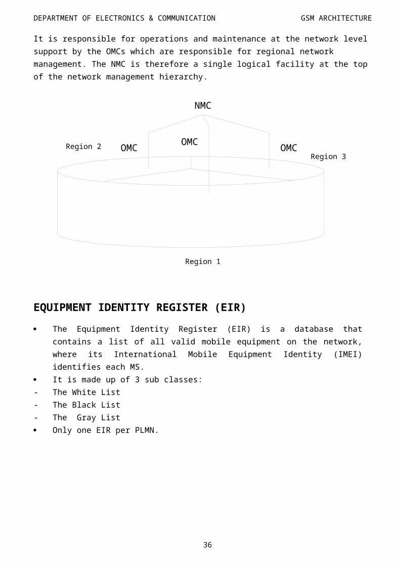
NETWORK MANAGEMENT CENTRE (NMC)
The network management centre offers the ability to provide hierarchical regionalized network management of a complete GSM system. It is responsible for operations and maintenance at the network level support by the OMCs which are responsible for regional network management. The NMC is therefore a single logical facility at the top of the network management hierarchy.
EQUIPMENT IDENTITY REGISTER (EIR)
The Equipment Identity Register (EIR) is a database that contains a list of all valid mobile equipment on the network, where its International Mobile Equipment Identity (IMEI) identifies each MS.
It is made up of 3 sub classes:- The White List- The Black List- The Gray List Only one EIR per PLMN.
GATEWAY MSC (GMSC)27
DEPARTMENT OF ELECTRONICS & COMMUNICATION GSM ARCHITECTURE
The GMSC is used to connect a subscriber of different network or operator with our own network.
If somebody from PSTN network wants to connect the MS, the call will first reach to GMSC.- Since the calling subscriber doesn’t know the location of MS, when the call reaches from PSTN
network to our GMSC, the GMSC will interrogate the HLR for location of the called subscriber.
- By means of location update, the HLR knows that the particular subscriber is in which MSC/VLR area.
The HLR will provide this information to GMSC. The GMSC in turn will now route the call to the correct MSC. This MSC will have now further more information about exact location information of called
subscriber and thus call is through. In GSM/PLMN all mobile terminated calls will be routed to GMSC and then to correct
MSC/BSC and further to MS.
OPERATION AND MAINTENENCE CENTRE (OMC)
OMC is connected to all equipment in the switching system and to the BSC and BTS.NETWORK AREA AND GATEWAY MSC The links between a GSM/PLMN network and the other PSTN, ISDN or PLMN networks is on
levels of International or National Transit Exchange. All the incoming calls to a GSM/PLMN Network are routed to GMSC. By way of interrogation and call routing the call is routed to correct MSC/BSC coverage area
and further it is routed to correct BTS. It is the place/node which has the function to route terminated calls to correct MSC and BSC
service area by way of HLR interrogation. In GSM/PLMN all mobile terminated calls will be routed to GMSC and then to correct
MSC/BSC and further to MS. MSC can have only one service area.
LOCATION AREA (LA)
The MSC/VLR service area is divided into several location areas. A location area is a part of MSC /VLR in which a mobile moves freely without updating
location information to MSC/VLR which controls location area. A location area is the area where a paging message is broadcasted in order to find the called
mobile subscriber. A location area can have several cells and depend on one or more BSCs, but it belongs to same
MSC/VLR. The location are can be identified by the system, using the Location Area Identity (LAI).
CELLULAR STRUCTURE28
DEPARTMENT OF ELECTRONICS & COMMUNICATION GSM ARCHITECTURE
The Cellular Structure
In a cellular system, the covering area of an operator is divided into cells. A cell corresponds to the covering area of one transmitter or a small collection of transmitters. The size of a cell is determined by the transmitter’s power.
The concept of cellular systems is the use of low power transmitters in order to enable the efficient reuse of the frequencies. In fact, if the transmitters used are very powerful the frequencies cannot be reused for hundreds of kilometres as they are limited to the covering area of the transmitter.
The frequency band allocated to a cellular mobile radio system is distributed over a group of cells and this distribution is repeated in all the covering area of an operator. The whole number of radio channels available can then be used in each group of cells that form the covering area of an operator. Frequencies used in a cell will be reused several cells away. The distance between the cells using the same frequency must be sufficient to avoid interference. The frequency reuse will increase considerably the capacity in number of users.
In order to work properly, a cellular system must verify the following two main conditions:
The power level of a transmitter within a single cell must be limited in order to reduce the interference with the transmitters of neighbouring cells. The interference will not produce any damage to the system if a distance of about 205 to 3 times the diameter of a cell is reversed between transmitters. The receiver filters must also be very performant.
Neighbouring cells cannot share the same channels. In order to reduce the interference, the frequencies must be reused only within a certain pattern.
In order to exchange the information needed to maintain the communication links within the cellular network, several radio channels are reserved for the signalling information.
CLUSTER
29
DEPARTMENT OF ELECTRONICS & COMMUNICATION GSM ARCHITECTURE
The cells are grouped into clusters. The number of cells in a cluster must be determined so that the cluster can be repeated continuously within the covering area of an operator. The typical cells in each clusters is very important. The smaller the number of cells per cluster is, the bigger the number of channels per cell will be. The capacities of each cell will be therefore increased. However a balance must be found in order to avoid the interference that could occur between neighbouring clusters. This interference is produced by the small size of the clusters (the size of the cluster is defined by the number of cells per cluster). The total number of channels per cell depends on the number of available channels and the type of cluster used.
A cluster Frequency Reuse
TYPES OF CELLS
The density of population in a country is so varied that different types of cells are used:
Macro cells
Micro cells
Selective cells
Umbrella cells
1. MACRO CELLS30
DEPARTMENT OF ELECTRONICS & COMMUNICATION GSM ARCHITECTURE
The macro cells are large cells for remote and sparsely populated areas.
2. MICRO CELLS
These cells are used for densely populated areas. By splitting the existing areas into smaller cells, the number of channels available is increased as well as the capacity of cells. The power level of the transmitters used in these cells is then decreased, reducing the possibility of interference between neighbouring cells.
3. SELECTIVE CELLS
It is not always to define a cell with a full coverage of 360 degrees. In some cases, cells with a particular shape and coverage are needed. These cells are called selective cells. A typical example of selective cells is the cells that may be located at the entrances of tunnels where coverage of 360 degrees is not needed. In this case, a selective cell with coverage of 120 degrees is used.
4. UMBRELLA CELLS
A freeway crossing very small cells produces an important number of handovers among the different small neighbouring cells. In order to solve this problem, the concept of umbrella cells is introduced. An umbrella cell covers several microcells. The power level insides an umbrella cell is increased comparing to the power levels used in the micro cells that form the umbrella cell. When the sped of the mobile is too high, the mobile is handed off to the umbrella cell. The mobile will then stay longer in the same cell (in this case the umbrella cell). This will reduce the number of handovers and the work of the network.
31
DEPARTMENT OF ELECTRONICS & COMMUNICATION GSM ARCHITECTURE
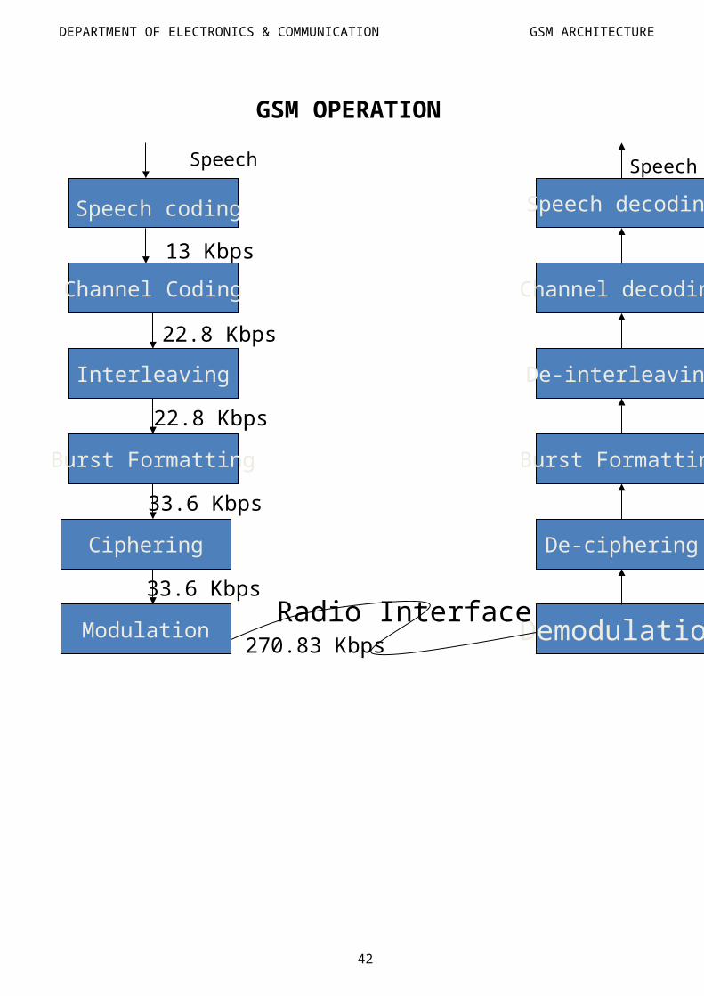
GSM OPERATION
32
Speech decoding
Channel decoding
De-interleaving
Burst Formatting
De-ciphering
DemodulationModulation
Ciphering
Burst Formatting
Interleaving
Channel Coding
Speech coding
Radio Interface
Speech Speech
13 Kbps
22.8 Kbps
22.8 Kbps
33.6 Kbps
33.6 Kbps
270.83 Kbps
DEPARTMENT OF ELECTRONICS & COMMUNICATION GSM ARCHITECTURE
GSM NETWORK IDENTIFIERS
Network identifies are numbers that a GSM network uses to locate a mobile subscriber when it is establishing a call to that subscriber.
As the network relies on these identities to route calls to subscribers, it is important that each identity is unique and correct.
Numbering plans are used to identify different networks as specified by the international telecommunication Union – Telecommunication (ITU-T). For a telephone number in the PSTN/ISDN network, ITU-T’s numbering plan E.164 is used.
1. Mobile Station ISDN Number (MSISDN) –The MSISDN is a number which uniquely identifies a mobile telephone subscription in the PSTN
numbering plan. This is the number dialled when calling a mobile subscriber. As the MSISDN is the actual
telephone number of the mobile subscriber, it is the only network identity that subscribers are aware of.
According to the CCITT recommendations the mobile telephone number or catalogue number to be dialled is composed in following way-
MS CC + NDC + SN
2. International Mobile Subscriber Identity (IMSI) –
The IMSI is information which uniquely identifies a subscriber in a GSM PLMN.
For the correct identification over the radio path and through the GSM PLMN network, a specific identity is attached to each subscriber. This Identity is called the INTERNATIONAL MOBILE SUBSCRIBER IDENTITY.
It is stored in the SIM card, the Home Location Register (HLR) and in serving Visitor Location Register (VLR).
The IMSI consists of three different part-- Mobile Country Code (MCC) (3 digit)- Mobile Network Code (MNC) (2 digit)- Mobile Subscriber Identification Number (MSIN) (max. 10 digit)-
3. Mobile Station Roaming Number (MSRN)- The Mobile Station Roaming Number MSRN is a temporary network identity which is
assigned during the establishment of a call to a roaming subscriber. HLR knows by means of location update procedure that in what MSC/VLR service area the
subscriber is currently registered. At reception of the MSRN, HLR sends it to GMSC which can now route the call to the
particular MSC/VLR where the called subscriber is currently located. The Interrogation call routing function (request for an MSRN), is part of the Mobile
Application Part (MAP).
33
DEPARTMENT OF ELECTRONICS & COMMUNICATION GSM ARCHITECTURE
4. Temporary Mobile Subscriber Identity (TMSI)
TMSI is a temporary IMSI number made known to an MS at registration. It is used to protect the subscriber’s identity on the air interface. The TMSI has local significance only (that is, within the MSC/VLR area) and is changed at
time intervals or when certain events occur such as location updating. The TMSI is used for the subscriber confidentially. The subscriber identify confidentiality feature means that the IMSI is not made available or
disclosed to unauthorised individuals, entities or processes. Every operator can choose TMSI structure, but should not consist of more than 8 digits.
5. International Mobile Station Equipment Identity (IMEI)
IMEI is used to uniquely identify MS equipment to the network. The IMEI is used for security procedures such as identifying stolen equipment and preventing
unauthorised access to the network. The IMEI consists of – TAC + FAC + SNR +SP TAC – Type Approval Code (6 digits) determined by the central GSM body. FAC – Final Assembly Code (2 digits) identifies the manufacturer. SNR – Serial Number (6 digits) an individual serial number of 6 digits uniquely identifying all
equipment within the TAC and FAC. According to GSM recommendation IMEI has the length of 15 digits.
6. Location Area Code (LAI)
The Location Area Identity (LAI) is a temporary network identity, which is also required for routing.
The two main purposes of the LAI are :-- Paging – This is used to inform the MSC of the LA in which the MS is currently situated.- Location updating of mobile subscribers LAI = MCC + MNC + LAC (mobile country code + mobile network code + location area
code). MCC = 3 digits (identifies the mobile country code of 3 digits, same as IMSI) MNC = 2 digits (identifies the mobile network code of 2 digits, same as IMSI) LAC= Location Area Code – this identifies a location area within a GSM PLMN network. The
maximum length of LAC is 16 bits, which enables 65,536 location areas in one GSM PLMN.
7. Cell Global Identity (CGI)
The Cell Global Identity (CGI) is used for identifying individual cells within a LA. Cell identification is achieved by adding a Cell Identity (CI) to the LAI components. CGI = MCC + MNC + LAC + CI Here CI = Cell Identity, identifies a cell within a location area consisting of maximum 16 bits.
34
DEPARTMENT OF ELECTRONICS & COMMUNICATION GSM ARCHITECTURE
8. Base Station Identity Code (BSIC)
The Base Station Identity Code (BSIC) enables MS’s to distinguish between different base stations sending on the same frequency.
BSIC = NCC + BCCNCC – Network Colour Code (3 bits) – identifies the GSM PLMN. This does not mean that it uniquely identifies the operator. NCC is primarily used for distinguishing the operators of border side.BCC – Base Station Colour Code (3 bits) – identifies the Base Station to help in identifying the BTS’s using same BCCH frequencies.
35
DEPARTMENT OF ELECTRONICS & COMMUNICATION GSM ARCHITECTURE
CONTROL CHANNELS
CONTROL CHANNELS
When an MS switched on, it searches for a BTS to connect to. The MS scans the entire frequency band, or, optionally, uses a list containing the allocated carrier frequencies for this operator.
When the MS finds the strongest carrier, it must then determine if it is a control channel. It does so by searching for a particular logical channel called Broadcast Control Channel (BCCH).
36
TC
H
(tr affic )
CC
H(co ntr ol)
BC
H
CC
CH
De dic ated
2.4 kb ps4.8 kb ps9.6 kb ps
FC
CH
(Fre que ncy corr ecti on)
SC
H(S
ync hro niza tion )P
CH
(Pagi ng)
RA
CH
(Ra ndo m
Acce ss)
AG
CH
(Ac ces s G
r ant)
SD
CC
H(S
tand Al one)
SA
CC
H(S
low-ass ocia ted)
FA
CC
H(F
ast- asso ciat ed)
Ha lf ra te 1 1.4k bps
Fu ll ra te 2 2.8k bps
Sp eec h
Da ta
DEPARTMENT OF ELECTRONICS & COMMUNICATION GSM ARCHITECTURE
A frequency carrying BCCH contains important information for an MS, including the current LA identity, synchronisation information and network identity. Without such information, an MS cannot work with a network.
This information is broadcast at regular intervals, leading to the term Broadcast Channel (BCH) information.
37
DEPARTMENT OF ELECTRONICS & COMMUNICATION GSM ARCHITECTURE
LOCATION UPDATE – BASIC STEPS
MOBILE BSS
38
Mobile looks for BCCH after switching on
RACH sends channel request
SDCCH request for location updating
AGCH receive SDCCH
SDCCH authentication
SDCCH switch to cipher mode
SDCCH allocate TMSI
SDCCH switch idle update mode
SDCCH authenticate response
SDCCH cipher mode acknowledge
SDCCH acknowledge new TMSI
DEPARTMENT OF ELECTRONICS & COMMUNICATION GSM ARCHITECTURE
LOCATION UPDATE
MS’s are constantly moving around in the cellular network. The MS location information stored in the VLR is the LA.
1. Changing cells within the LA.If an MS changes cells within a LA, the network is not updated.The MS knows that the new cell belongs to the same LA by listening to BCCH in the new cell.The BCCH broadcasts the cell’s LAI. The MS compares the last LAI received with the new LAI. If they are the same, it means that the MS has not changed LA’s and does not need to inform the network.
2. Location Updating, Same MSC/VLRIf an MS detects a change in LAI on the BCCH, it informs the network.When the MS sends the Location Updating message, the MSC/VLR determines whether it is an MS, which is already registered, or if it is an MS visiting from another MSC/VLR.The MS listens to the BCCH in the new cell to determine the LAI. The received LAI information is compared to the old one. If they differ, a location update is necessary.
The MS establishes a connection with the network via SDCCH.Authentication is performed
If authentication is successful, the MS sends a Location Updating Request to the system. The system acknowledges the Location Updating &request BTS and MS to release the channel.
3. Location Updating, New MSC/VLRWhen an MS roams into a new LA, location updating is performed. However, unknown to the MS, the LA may belong to the new MSC/VLR. When the Location update request is received by the new VLR, it executes the procedure below.
Authentication is performed. If authentication is successful, the VLR checks its database to determine whether or not it has a record for this MS-subscription.
When the VLR finds no record for the MS, it sends a request to the subscriber’s HLR for a copy of the MS- subscription.
The HLR passes the information to the VLR and updates its location information for the subscriber. The HLR instructs the old VLR to delete the info it has about the MS subscription.
The VLR stores its subscriber information for the MS including the latest location and status (idle). The VLR sends acknowledgement to the MS.
4. Location Updating, type periodic Registration Periodic registration is a feature which forces MS’s to send a registration message to the
network at predefined intervals. If an MS should miss such a registration, the network will mark the MS as detached. Thisoccur if an MS is out of area of coverage and ensures that needles paging is not performed. If the network uses periodic registration, the MS will be informed, on the BCCH of how often
periodic registration must be performed. Periodic registration has an acknowledgement message. The MS tries to register until it receives this message.
39
DEPARTMENT OF ELECTRONICS & COMMUNICATION GSM ARCHITECTURE
ATTACHING TO THE NETWORK
IMSI attach
When an MS is switched on, the IMSI attach procedure is executed. This involves the following steps:-1. The MS sends an IMSI attach message to the network indicating that it has changed state to
idle.2. The VLR determines whether there is a record for the subscriber already present. If not, the
VLR contacts the subscriber’s HLR for a copy of the subscription information.3. The VLR updates the MS status to idle.4. Acknowledgement is sent to the MS.
DETATCHING FROM THE NETWORK
IMSI Detach
IMSI detach enables the MS to indicate the network that it is switched off. At power off, the MS sends an IMSI detach message to the network. On reception, the VLR
marks the corresponding IMSI as detached. The HLR is not informed. No acknowledgement is sent to the MS.
Implicit Detach
If the MS sends an IMSI detach message to the system and the radio link quality is poor, the system might not be able to decode the information. Because no acknowledgement is sent to the MS, no further attempt is made.
In this case, the system still regards the MS as detached. If periodic registration is in use, the system will soon determine that the MS is detached. The VLR then performs an implicit detach, marking the MS as detached.
MS Purging
MS purging is used to inform the HLR that the VLR is about to remove a subscriber record from the VLR.
The HLR then sets the MS purged flag and treats the subscriber as unreachable. This saves necessary network signalling and database lookup.
40
DEPARTMENT OF ELECTRONICS & COMMUNICATION GSM ARCHITECTURE
CALL FLOW
CALL FROM AN MS
This section describes what happen when a mobile subscriber wants to set up a voice call to a subscriber in the PSTN.
1. The MS uses RACH to ask for a signalling channel2. The BSC allocates a signalling channel, using AGCH.3. The MS sends a call setup request via SDDCH to the MSC/VLR. Over SDCCH all signalling
preceding a call takes place.4. The MSC/VLR instructs the BSC to allocate an idle TCH. The BTS and MS are told to tune to
the TCH.5. The MSC/VLR forwards the dialled number to an exchange in the PSTN¸ which establishes the
connection to the subscriber.6. If the dialled subscriber answers, the connection is established.
Call related information needs to be transported from the mobile phone to the Mobile Switching Center (MSC). This requires the establishment of a Radio Resource (RR) connection to MSC. The first phase of the call setup just sets up this RR connection.
RR CHANNEL REQUEST RR
Connection establishment is triggered by sending the Channel Request message. This RACH message requests the Base Station System (BSS) for allocation for radio resources for the RR connection setup. The mobile now waits for an assignment on the Access Grant Channel (AGCH). At this point the mobile is listening to the AGCH for a reply.
41
DEPARTMENT OF ELECTRONICS & COMMUNICATION GSM ARCHITECTURE
ORIGINATING CALL FLOW
1. The MS sends dialled number to BSS.2. BSS sends dialled number to MSC.
3, 4. MSC interrogates the VLR, if the MS is allowed the requested service. If the service is allowed, MSC asks BSS to allocate resources for call.
5. MSC routes the call to GMSC6. GMSC routes the call to local exchange of called use
7, 8,9,10 Answer back tone is routed from called user to MS via GMSC, MSC, BSS
42
DEPARTMENT OF ELECTRONICS & COMMUNICATION GSM ARCHITECTURE
CALL TO AN MS
The major difference between a call to an MS and a call from an MS is that in a call to an MS, the exact location of the mobile subscriber is unknown.
Therefore, the MS must be located using Paging before a connection can be established. Below is the description of the call setup procedure for a call from a PSTN subscriber to a
mobile subscriber. A call from an MS to a mobile subscriber operates according to the same process, the only
difference being that the GMSC is contacted by another MSC/VLR instead of by a PSTN node.1. The PSTN subscriber keys in the MS’s telephone number (MSISDN). The MSISDN is
analyzed in the PSTN, which identifies that this is a call to a mobile network subscriber. A connection is established to the MS’s home GMSC.
2. The GMSC analyses the MSISDN to find out which HLR the MS is registered in, and queries the HLR for information about how to route the call to the serving MSC/VLR.
3. The HLR translates MSISDN into IMSI, and determines which MSC/VLR is currently serving the MS. The HLR also checks if the service, “call forwarding” is activated, if so, the call is rerouted.
4. The HLR requests an MSRN from the serving MSC/VLR.5. The MSC/VLR returns an MSRN via HLR to the GMSC.6. The GMSC analyses the MSRN and routes the call to the MSC/VLR.7. The MSC/VLR knows which LA the MS is located in. A paging message is sent to the BSC’s
controlling the LA.8. The BSC’s distribute message to the BTS’s in the desired LA. The BTS transmit the message
over the air interface using PCH. To page the MS, the network uses an IMSI or TMSI valid only in the current MSC/VLR service area.
9. When the MS detects the paging message, it sends a request on RACH for a SDCCH.10. The BSC provides a SDCCH, using AGCH.11. SDCCH is used for the setup procedures. Over SDCCH all signalling preceding a call takes
place.12. The MSC/VLR instructs the BSC to allocate an idle TCH. The BTS and MS are told to tune to
the TCH. The mobile phone rings. If the subscriber answers, then the connection is established. 13. Since the location area might spawn several cells, a paging mechanism is used to locate the
subscriber. The MSC/VLR uses a TMSI (Temporary Mobile Subscriber Identify) to address the mobile phone. The TMSI is used so as to protect the privacy of the called subscriber. Note that, the BSSMAP PAGING message will be sent to all the BSCs that handle the Maryland Location Area.
43
DEPARTMENT OF ELECTRONICS & COMMUNICATION GSM ARCHITECTURE
TERMINATING CALL FLOW
1. Calling a GSM subscriber.2. Forwarding call to GMSC.3. Signal setup to HLR.4, 5 Request MSRN from VLR.6. Forward responsible MSC to GMSC.7. Forward call to current MSC.8,9. Get current status of MS.10, 11. Paging of MS.12, 13. MS answers.14, 15. Security Checks.16, 17. Set up connection.
44
DEPARTMENT OF ELECTRONICS & COMMUNICATION GSM ARCHITECTURE
HANDOVERS
The process of changing cells during a call is called HANDOVERS in GSM terminology. To choose the best target cell, the MS and the BTS perform measurements. Because the MS
contributes to the handover decision, this type of handover is often Mobile Assisted Handover (MAHO).
The handover function executes the actual switching of the connection to another channel.
If the cell belongs to another BSC, the MSC must be involved in the handover. However it acts only upon order from BSC. None of the decision making is performed in the MSC, since it has no real time information about the connection.
A special type of handover is the Intra Cell Handover. It is performed when the BSC consider the quality of the connection too low, but receives no indication from the measurements that another cell is a better cell.
In that condition the BSC switches the connection to another channel in the same cell. Hopefully the quality improves.
The idle timeslot measurements provide guidance in the choice of a better channel.
Handover can also be used for the load balancing between the cells. During the call setup in a congested cell, the mobile station can be forced over a cell with less traffic if an acceptable connection quality is indicated in the next cell.
Another area where forced handover is useful is maintained. By forced handovers, channels can be released from the traffic if necessary for maintenance reasons. The above types of handover are part of Network Initiated Handover.
The MSC communicates directly with the mobile station in matters related to the call control and mobility management.
A special transparency function is therefore provided in the BSC, which allows the MSC to signal via connection.
45
DEPARTMENT OF ELECTRONICS & COMMUNICATION GSM ARCHITECTURE
ADVANTAGES OF GSM OVER ANALOG SYSTEM
Capacity increases. Reduced RF transmission power and longer battery life. International roaming capability. Better security against fraud (through terminal validation and user authentication). Encryption capability for information security and privacy. Compatibility with ISDN, leading to wider range of services.
GSM APPLICATIONS
Mobile telephony. GSM-R. Telemetry services. Fleet management. Automatic meter reading. Toll collection Remote control and fault reporting of DG sets. Value added services.
FUTURE OF GSM
Today GSM is used by 2.3 billion people worldwide and the strong growth is expected to be maintained.